Battery Management Systems - Battery Power Magazine
Battery Management Systems - Battery Power Magazine
Battery Management Systems - Battery Power Magazine

Create successful ePaper yourself
Turn your PDF publications into a flip-book with our unique Google optimized e-Paper software.
Feature<br />
Double Layer Capacitors<br />
Low ESR Electrochemical Double Layer Capacitors<br />
Bharat Rawal, Chris Reynolds and Bob Knopsnyder<br />
AVX<br />
Concepts of Electrochemical Double Layer Capacitors<br />
(EDLCs), also known as super-capacitors or electrochemical<br />
capacitors, were proposed by Helmholtz in 1860. Early practical<br />
devices based on these concepts were produced in late 1970s,<br />
more than 100 years after these ideas were introduced. These<br />
capacitors, with equivalent series resistance (ESR) values of<br />
tens to hundreds of ohms at about 2.5 and 5 volts, have now<br />
been used for back-up applications for more than 30 years.<br />
Early applications included back power up for clocks, in case of<br />
power failure, in consumer applications like VCRs, radios, DVD<br />
players / recorders and others. These clocks use very low currents<br />
(typically less than 10 μA at low voltages) or in real time<br />
clocks (RTCs) in many electronic circuits. These low power<br />
applications found these devices to be an excellent compromise<br />
between batteries, which had to be constantly replaced and<br />
electrostatic / electrolytic capacitors, which did not have enough<br />
capacitance in practical sized packages like “button” cells.<br />
With advances in many telecom and other applications in<br />
the mid 1990s, customers with new applications expressed a<br />
need for capacitors for high pulse power applications (small,<br />
low profile capacitors which can provide currents of several<br />
amps at around 3 to 5 volts). These capacitors were required<br />
to have capacitance values of tens to hundreds of milli-Farads<br />
(mF) with ESR values of fifty to several hundred milli-ohms<br />
(mΩ). In less than five years this resulted in the development<br />
of low profile, low ESR (20 to several hundred mΩ), high<br />
capacitance (6.8 mF to 1 Farad) EDLCs (or super-capacitors)<br />
with voltage ratings of 2.5 to 16 volts. This shows the rapid<br />
pace of technology development in the last 20 years. These<br />
components have now been used for about 10 years to provide<br />
high current pulses of several amps in many applications<br />
including, wireless barcode scanners, smart metering, medical<br />
hand held devices, battery chatter and for many types of GSM<br />
/ GPRS applications. In the past 24 months these low ESR<br />
EDLC devices are now being designed in new applications<br />
where extending battery life is critical, in USB powered applications<br />
where the low ESR of these capacitors enables large<br />
current pulses needed for their operation, and in energy harvesting<br />
applications made possible because these components<br />
have very low leakage currents. Both of these characteristics,<br />
low leakage currents and low ESR, found in these low ESR<br />
EDLCs, result in these capacitors being preferred over other<br />
capacitors or over other small batteries which have also been<br />
tested for these and other similar applications.<br />
General Construction of EDLCs<br />
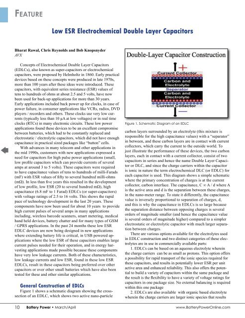
Figure 1 shows a schematic diagram showing the crosssection<br />
of an EDLC, which shows two active nano-particle<br />
Figure 1. Schematic Diagram of an EDLC<br />
carbon layers surrounded by an electrolyte (this mixture is<br />
responsible for the high capacitance values) with a “separator”<br />
in between, and these carbon layers are in contact with current<br />
collectors, which carry the current to the outside world. To<br />
just illustrate the performance of these devices, the two carbon<br />
layers, each in contact with a current collector, consist of two<br />
capacitors in series and hence the name Double Layer Capacitor<br />
or DLC, and since the charge carriers within the capacitor<br />
is ionic in nature the term electrochemical DLC (or EDLC) for<br />
each capacitor is used. This diagram shows a simple schematic<br />
where the primary concentration of charges is at the current<br />
collector, carbon interface. The capacitance, C ∞ A / d where A<br />
is the active area and d is the separation between these charges,<br />
in the nano-meter range. To state it differently, the capacitance<br />
value is inversely proportional to separation of charges, d,<br />
and this is why the capacitance in EDLCs is so large because<br />
the separation distance between opposing charges is several<br />
orders of magnitude smaller (and hence the capacitance value<br />
is several orders of magnitude higher) compared to a simpler<br />
electrostatic or electrolytic capacitor with much larger separation<br />
between charges.<br />
There are various options available for the electrolytes used<br />
in EDLC construction and two distinct categories of these electrolytes<br />
are in use in commercially available parts:<br />
1. EDLCs can be based on an aqueous electrolyte wherein<br />
the charge carriers can be as small as protons. This option offers<br />
a possibility for rapid transport of the ionic species required for<br />
these capacitors, and results in potentially lower ESR per unit<br />
active area and enhanced reliability. This also offers the potential<br />
to build a variety of capacitors within the same package and<br />
the result is the flexibility to have a variety of voltage ratings for<br />
capacitors in one package size. No external balancing is required<br />
within this one package<br />
2. EDLCs are also available with organic based electrolyte<br />
wherein the charge carriers are larger ionic species that results<br />
in higher ESR per unit active area and resultant higher voltage per cell. This advantage<br />
offers the potential for higher capacitance per unit volume as lesser number of cells are<br />
needed in series for these EDLCs.<br />
Applications<br />
In pulse applications, an energy source (battery) or a pulse power device (capacitor)<br />
or a combination of both, provide a constant current pulse, of magnitude I, in amps, to<br />
the circuit. Two performance characteristics of the capacitor, equivalent series resistance<br />
(ESR in ohms) and the effective capacitance (C in Farads), are particularly important in<br />
these applications. The instantaneous voltage drop, ΔVesr, is directly proportional to ESR<br />
of the device, and the corresponding voltage drop is<br />
ΔVesr = I * ESR<br />
And the time dependent voltage drop, ΔVc, is inversely proportional to the<br />
capacitance, and<br />
ΔVc = I * Δt / C<br />
Where Δt is the duration of the pulse. The total voltage drop ΔV may be expressed as<br />
ΔV = ΔVesr + ΔVc<br />
Longer <strong>Battery</strong> Life<br />
In an application with only a Li-ion battery, a large GSM current pulse (2 amp pulse<br />
for 577 μS with a duty cycle of 12.5 percent) drawn from the battery will result in a<br />
corresponding voltage trace shown by the blue curve in Figure 2a. In the graph the blue<br />
curve appears to be a continuous trace because the pulse width is so small even though it<br />
is a square wave. If a supercapacitor<br />
is used in parallel<br />
with this battery, the same<br />
trace may be shown by the<br />
red curve in this figure and<br />
this clearly demonstrates<br />
that the effectively higher<br />
voltage through-out the use<br />
time will keep the whole<br />
circuit operating above<br />
the cutoff voltage of 3.5<br />
volts for a longer time,<br />
which in effect results in a<br />
longer battery life. This is<br />
why in many applications<br />
a super-capacitor is used<br />
in parallel with a battery.<br />
Similar results are observed<br />
for a NiMH battery in Figure<br />
2b where the effective battery<br />
life is shown to be almost double.<br />
Figure 2a. Voltage Trace with Only <strong>Battery</strong> Vs Voltage Trace<br />
with <strong>Battery</strong> + Capacitor<br />
<strong>Battery</strong> Chatter<br />
Demand for hand held products, like portable x-ray equipment, smart PDAs and smart<br />
hand held scanners are powered by rechargeable or primary Li-ion batteries or by alkaline<br />
batteries at the low end of these markets. Portability has increased the incidence of these devices<br />
being accidently dropped or unknowingly subjected to other mishandling. This action<br />
may result in momentary loss of contact between the batteries and the battery connectors<br />
and this is referred to as battery chatter. During use it is common for many of these devices<br />
to be processing data or saving data on a ROM and battery chatter results in loss of key<br />
AVX Continued on Page 12<br />
Overheating<br />
Batteries...<br />
Preventing<br />
Catastrophes.<br />
It is well known that<br />
Li-ion batteries can<br />
potentially overheat with<br />
catastrophic results. A<br />
recent Business Week<br />
article points this out.*<br />
Effective understanding<br />
of temperature and<br />
voltage together gives<br />
insight into this potential<br />
problem. This ability<br />
to correlate changing<br />
readings of both is what<br />
MEASURpoint does well.<br />
*Business Week, July 16, 2009:<br />
“Future Shock for Electric Cars”<br />
Correlation of Temperature<br />
and Voltage Measurement<br />
800-525-8528<br />
www.datatranslation.com<br />
10 <strong>Battery</strong> <strong>Power</strong> • March/April<br />
www.<strong>Battery</strong><strong>Power</strong>Online.com<br />
www.<strong>Battery</strong><strong>Power</strong>Online.com March/April • <strong>Battery</strong> <strong>Power</strong> 11