2002 Portofino Series Owners Manual - Sundance Spas
2002 Portofino Series Owners Manual - Sundance Spas
2002 Portofino Series Owners Manual - Sundance Spas

Create successful ePaper yourself
Turn your PDF publications into a flip-book with our unique Google optimized e-Paper software.
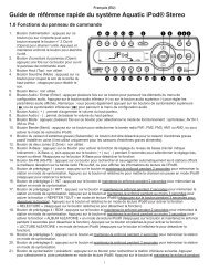
15.0 120/240 VAC Convertible Circuit Diagram<br />
This wiring diagram is used for all US/Canada 120/240 VAC (60 Hz)<br />
convertible models.<br />
Control<br />
Panel<br />
J1<br />
Temperature Sensor<br />
J2<br />
Hi-limit/Freeze<br />
Sensor<br />
J3<br />
Flow Switch<br />
Temperature<br />
Display Jumper:<br />
JP1 7-8 ON =<br />
°C Temp Display<br />
JP1 7-8 OFF =<br />
°F Temp Display*<br />
*Factory Setting<br />
BLK<br />
Heater<br />
1.0 kW @ 120 VAC<br />
4.0 kW @ 240 VAC<br />
6530-289, Rev-A<br />
Spa<br />
Light<br />
Transformer<br />
120 VAC<br />
JP1<br />
8 7<br />
6 5<br />
4 2 3<br />
1<br />
BLK<br />
BLK<br />
Circ.<br />
Pump<br />
WHT<br />
J4<br />
WHT<br />
BLK<br />
WHT<br />
F1<br />
20A<br />
250V<br />
SC-20<br />
RED<br />
BLK<br />
BLK<br />
WHT<br />
LO<br />
Main<br />
Pump<br />
HI<br />
RED<br />
RED BLK<br />
RED<br />
1<br />
WHT<br />
2<br />
BLK<br />
3<br />
TB1<br />
Standard 120 VAC 3-Wire Connection<br />
(60 Hz, 1 Phase, 15 A Service)<br />
Use copper conductors ONLY. Wire size must be<br />
appropriate per NEC and/or local codes.<br />
Ozonator<br />
O3<br />
GRN<br />
Optional 120/240 VAC<br />
4-Wire Convertible<br />
Heater Connection<br />
1. Remove and discard the<br />
factory installed GFCI Cord.<br />
2. Move RED* wire from<br />
position #1 to position #3<br />
on terminal block TB1 as<br />
shown below.<br />
3. Permanently connect to<br />
the power supply. Use<br />
copper conductors ONLY.<br />
Wire size must be<br />
appropriate per NEC and/or<br />
local codes.<br />
4. If hot tub is to be operated<br />
on 25 A service, make sure<br />
the jumper provided at<br />
location JP1 #1&2 on the<br />
circuit board is installed. If<br />
hot tub is to be operated on<br />
40 A service, remove the<br />
jumper JP1 #1&2 on the<br />
circuit board.<br />
RED*<br />
BLK<br />
1 2 3<br />
TB1<br />
GRN<br />
WHT BLK RED<br />
30