Adjustment And Measurement Unit - Halton
Adjustment And Measurement Unit - Halton
Adjustment And Measurement Unit - Halton

You also want an ePaper? Increase the reach of your titles
YUMPU automatically turns print PDFs into web optimized ePapers that Google loves.
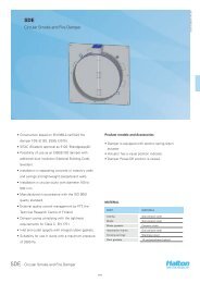
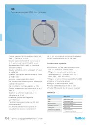
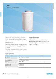
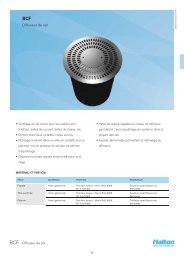
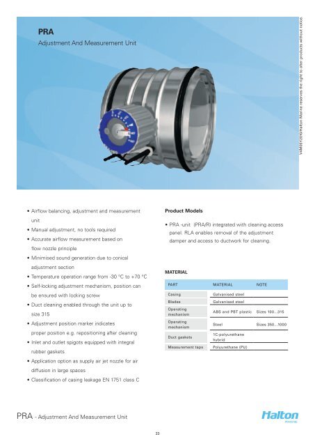
PRA<br />
<strong>Adjustment</strong> <strong>And</strong> <strong>Measurement</strong> <strong>Unit</strong><br />
V4M05Y2010/<strong>Halton</strong> Marine reserves the right to alter products without notice.<br />
• Airflow balancing, adjustment and measurement<br />
unit<br />
• Manual adjustment, no tools required<br />
• Accurate airflow measurement based on<br />
flow nozzle principle<br />
• Minimised sound generation due to conical<br />
adjustment section<br />
• Temperature operation range from -30 °C to +70 °C<br />
• Self-locking adjustment mechanism, position can<br />
be ensured with locking screw<br />
• Duct cleaning enabled through the unit up to<br />
size 315<br />
• <strong>Adjustment</strong> position marker indicates<br />
proper position e.g. repositioning after cleaning<br />
• Inlet and outlet spigots equipped with integral<br />
rubber gaskets<br />
• Application option as supply air jet nozzle for air<br />
diffusion in large spaces<br />
• Classification of casing leakage EN 1751 class C<br />
Product Models<br />
• PRA -unit (PRA/R) integrated with cleaning access<br />
panel. RLA enables removal of the adjustment<br />
damper and access to ductwork for cleaning.<br />
MATERIAL<br />
PART MATERIAL NOTE<br />
Casing<br />
Blades<br />
Operating<br />
mechanism<br />
Operating<br />
mechanism<br />
Duct gaskets<br />
<strong>Measurement</strong> taps<br />
Galvanised steel<br />
Galvanised steel<br />
ABS and PBT plastic Sizes 100...315<br />
Steel Sizes 350...1000<br />
1C-polyurethane<br />
hybrid<br />
Polyurethane (PU)<br />
PRA - <strong>Adjustment</strong> <strong>And</strong> <strong>Measurement</strong> <strong>Unit</strong><br />
33
QUICK SELECTION<br />
D qmin qmax<br />
[mm] [l/s] [m 3 /h] [l/s] [m 3 /h]<br />
100 8 28 47 170<br />
125 12 44 74 265<br />
160 20 72 121 434<br />
200 31 113 188 679<br />
250 49 177 295 1060<br />
315 78 281 468 1683<br />
350 96 346 577 2078<br />
400 126 452 754 2714<br />
500 196 707 1178 4241<br />
630 312 1122 1870 6733<br />
800 503 1810 3016 10857<br />
1000 785 2827 4712 16965<br />
qmin<br />
qmax<br />
1 m/s duct velocity<br />
6 m/s duct velocity - recommended maximum<br />
airflow for comfort applications<br />
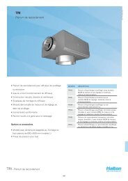
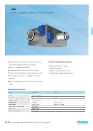
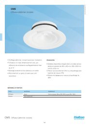
DIMENSIONS<br />
ØD<br />
ØD<br />
57<br />
H<br />
36<br />
70<br />
142<br />
39 114<br />
195<br />
PRA 100...315<br />
PRA 350...1000<br />
NS<br />
ØD<br />
100 99<br />
125 124<br />
160 159<br />
200 199<br />
250 249<br />
315 314<br />
NS ØD H<br />
350 349 70<br />
400 399 70<br />
500 499 70<br />
630 629 70<br />
800 799 70<br />
1000 999 85<br />
PRA - <strong>Adjustment</strong> <strong>And</strong> <strong>Measurement</strong> <strong>Unit</strong><br />
34
Function<br />
The airflow rate is adjusted by turning the adjustment<br />
knob in order to change the aperture size of the<br />
adjustment cone formed by iris blades. Once the<br />
opening area is reduced, the airflow rate decreases<br />
and the total pressure loss caused by the device<br />
increases.<br />
The airflow can be determined by measuring the<br />
differential pressure in the measurement taps.<br />
PRA 100…315<br />
The operating mechanism is positioned partly outside<br />
the device and between the adjustment cone and<br />
casing. The unit can be cleaned with normal duct<br />
sweeping equipment when the device is fully opened.<br />
PRA 350…1000<br />
The operating mechanism is located partly outside the<br />
device and inside the adjustment cone. The device can<br />
be cleaned with normal duct sweeping equipment,<br />
when the device is fully opened and the cleaning<br />
equipment is passed carefully through the operating<br />
mechanism.<br />
Supply air jet nozzle PRA/S<br />
The PRA-unit can also be used as a supply air nozzle<br />
in e.g. industrial spaces. Refer to the technical data for<br />
PRA/S -model presented in the technical performance<br />
chapter.<br />
V4M05Y2010/<strong>Halton</strong> Marine reserves the right to alter products without notice.<br />
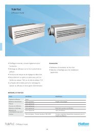
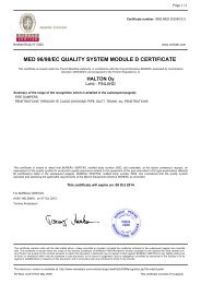
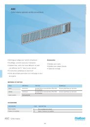
Installation<br />
Sizes 100...315<br />
CODE DESCRIPTION<br />
1 Air flow direction indicator<br />
2 <strong>Adjustment</strong> knob<br />
3 Locking screw of adjustment Position<br />
4 <strong>Adjustment</strong> position indicator<br />
5 <strong>Adjustment</strong> position marker for Cleaning<br />
6 <strong>Adjustment</strong> scale<br />
7 <strong>Measurement</strong> taps<br />
Sizes 350...1000<br />
CODE DESCRIPTION<br />
1 <strong>Adjustment</strong> position indicator<br />
2 <strong>Adjustment</strong> knob<br />
3 <strong>Measurement</strong> taps<br />
PRA - <strong>Adjustment</strong> <strong>And</strong> <strong>Measurement</strong> <strong>Unit</strong><br />
35
Installation<br />
Fix the damper to the ductwork e.g. with rivets.<br />
Ensure that the rivet does not prevent the operation of<br />
the PRA. The position of the rivet must be at least 10<br />
mm from the duct end.<br />
The PRA iris damper shall be installed in the ductwork<br />
taking into account the safety distances outlined in<br />
the installation guidelines. Safety distances are not<br />
required next to duct transitions between only one<br />
nominal duct size.<br />
The orientation of the unit shall correspond to the<br />
airflow direction. The airflow direction is marked with<br />
an arrow indicator on the label on the casing. In order<br />
to get accurate measurement readings the orientation<br />
of the unit shall be selected so that the location of the<br />
measurement taps (below the knob) corresponds to<br />
the installation guidelines.<br />
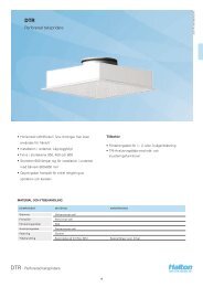
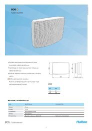
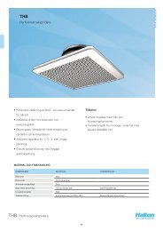
Safety distances<br />
Recommended safety distance in order to get<br />
accurate measurement readings are presented in the<br />
figure below.<br />
Direct duct with no flow disturbances<br />
- safety distance 4 D upflow of the PRA unit<br />
- safety distance 1 D downflow of the PRA unit<br />
In cases where recommended safety distances cannot<br />
be met, use the correction factors of the attached<br />
figures for determination of the airflow rate.<br />
Note the position of the measurement taps marked in<br />
the figures.<br />
1 1 2 1 2 2<br />
3<br />
3<br />
3<br />
4<br />
4<br />
4<br />
5 5 6 5 6 6<br />
7<br />
7<br />
8<br />
7<br />
8<br />
8<br />
Figure Installation case Duct velocity upflow of the pra unit K-factor<br />
1 Recommended safety distance 1<br />
2 T-branch, supply air 0.95 (1D) ...1.00 (4D)<br />
3 T-branch, exhaust air > 2 m/s 1… 2 m/s 0.95 (1D) ...1.00 (4D) 0.90 (1D) ...1.00 (4D)<br />
4 90° bend 0.97 (0D) ...1.00 (4D)<br />
5 T-branch 1<br />
6 90° bend 1<br />
7 Upflow of a supply air device 1<br />
8 T-branch 1<br />
PRA - <strong>Adjustment</strong> <strong>And</strong> <strong>Measurement</strong> <strong>Unit</strong><br />
36