Composite columns - Eurocodes
Composite columns - Eurocodes
Composite columns - Eurocodes

Create successful ePaper yourself
Turn your PDF publications into a flip-book with our unique Google optimized e-Paper software.
G. Hanswille<br />
Univ.-Prof. Dr.-Ing.<br />
Institute for Steel and<br />
<strong>Composite</strong> Structures<br />
University of Wuppertal-Germany<br />
<strong>Eurocodes</strong><br />
Background and Applications<br />
Dissemination of information for training<br />
18-20 February 2008, Brussels<br />
Eurocode 4<br />
<strong>Composite</strong> Columns<br />
Univ. - Prof. Dr.-Ing. Gerhard Hanswille<br />
Institute for Steel and <strong>Composite</strong> Structures<br />
University of Wuppertal<br />
Germany<br />
1
Contents<br />
G. Hanswille<br />
Univ.-Prof. Dr.-Ing.<br />
Institute for Steel and<br />
<strong>Composite</strong> Structures<br />
University of Wuppertal-Germany<br />
Part 1: Introduction<br />
Part 2: General method of design<br />
Part 3: Plastic resistance of cross-sections and interaction curve<br />
Part 4: Simplified design method<br />
Part 5: Special aspects of <strong>columns</strong> with inner core profiles<br />
Part 6: Load introduction and longitudinal shear<br />
2
G. Hanswille<br />
Univ.-Prof. Dr.-Ing.<br />
Institute for Steel and<br />
<strong>Composite</strong> Structures<br />
University of Wuppertal-Germany<br />
Part 1: Introduction<br />
3
<strong>Composite</strong> <strong>columns</strong><br />
G. Hanswille<br />
Univ.-Prof. Dr.-Ing.<br />
Institute for Steel and<br />
<strong>Composite</strong> Structures<br />
University of Wuppertal-Germany<br />
concrete encased<br />
sections<br />
concrete<br />
filled hollow<br />
sections<br />
partially concrete<br />
encased sections<br />
4
Concrete encased sections<br />
G. Hanswille<br />
Univ.-Prof. Dr.-Ing.<br />
Institute for Steel and<br />
<strong>Composite</strong> Structures<br />
University of Wuppertal-Germany<br />
advantages:<br />
• high bearing resistance<br />
• high fire resistance<br />
• economical solution with regard to<br />
material costs<br />
disadvantages:<br />
• high costs for formwork<br />
• difficult solutions for connections<br />
with beams<br />
• difficulties in case of later<br />
strengthening of the column<br />
• in special case edge protection is<br />
necessary<br />
5
Partially concrete encased sections<br />
G. Hanswille<br />
Univ.-Prof. Dr.-Ing.<br />
Institute for Steel and<br />
<strong>Composite</strong> Structures<br />
University of Wuppertal-Germany<br />
advantages:<br />
• high bearing resistance, especially in case<br />
of welded steel sections<br />
• no formwork<br />
• simple solution for joints and load<br />
introduction<br />
• easy solution for later strengthening and<br />
additional later joints<br />
• no edge protection<br />
disadvantages:<br />
• lower fire resistance in comparison with<br />
concrete encased sections.<br />
6
Concrete filled hollow sections<br />
G. Hanswille<br />
Univ.-Prof. Dr.-Ing.<br />
Institute for Steel and<br />
<strong>Composite</strong> Structures<br />
University of Wuppertal-Germany<br />
advantages:<br />
• high resistance and slender <strong>columns</strong><br />
• advantages in case of biaxial bending<br />
• no edge protection<br />
disadvantages :<br />
• high material costs for profiles<br />
• difficult casting<br />
• additional reinforcement is needed for fire<br />
resistance<br />
7
Concrete filled hollow sections with<br />
additional inner profiles<br />
G. Hanswille<br />
Univ.-Prof. Dr.-Ing.<br />
Institute for Steel and<br />
<strong>Composite</strong> Structures<br />
University of Wuppertal-Germany<br />
advantages:<br />
• extreme high bearing resistance in<br />
combination with slender <strong>columns</strong><br />
• constant cross section for all stories is<br />
possible in high rise buildings<br />
• high fire resistance and no additional<br />
reinforcement<br />
• no edge protection<br />
disadvantages:<br />
• high material costs<br />
• difficult casting<br />
8
G. Hanswille<br />
<strong>Composite</strong> <strong>columns</strong> with hollow sections Univ.-Prof. Dr.-Ing.<br />
Institute for Steel and<br />
<strong>Composite</strong> Structures<br />
and additional inner core-profiles<br />
University of Wuppertal-Germany<br />
Commerzbank<br />
Frankfurt<br />
9
Design of composite <strong>columns</strong><br />
according to EN 1994-1-1<br />
G. Hanswille<br />
Univ.-Prof. Dr.-Ing.<br />
Institute for Steel and<br />
<strong>Composite</strong> Structures<br />
University of Wuppertal-Germany<br />
Verifications for composite <strong>columns</strong><br />
Resistance of the member for<br />
structural stability<br />
General method<br />
Simplified method<br />
Resistance to local Buckling<br />
Introduction of loads<br />
Longitudinal shear outside the areas of load<br />
introduction<br />
10
Methods of verification in accordance<br />
with EN 1994-1-1<br />
G. Hanswille<br />
Univ.-Prof. Dr.-Ing.<br />
Institute for Steel and<br />
<strong>Composite</strong> Structures<br />
University of Wuppertal-Germany<br />
Methods of verification<br />
general method:<br />
• any type of cross-section and any<br />
combination of materials<br />
simplified method:<br />
• double-symmetric cross-section<br />
• uniform cross-section over the member length<br />
• limited steel contribution factor δ<br />
• related Slenderness smaller than 2,0<br />
• limited reinforcement ratio<br />
• limitation of b/t-values<br />
11
Resistance to lokal buckling<br />
G. Hanswille<br />
Univ.-Prof. Dr.-Ing.<br />
Institute for Steel and<br />
<strong>Composite</strong> Structures<br />
University of Wuppertal-Germany<br />
concrete encased cross-sections<br />
b<br />
b c<br />
c y<br />
c y<br />
c<br />
⎧40<br />
mm<br />
z<br />
Verification is not necessary where c z ≥ ⎨<br />
⎩ b / 6<br />
h h c<br />
y<br />
c<br />
concrete filled hollow section<br />
z<br />
z<br />
t<br />
⎛ d⎞<br />
2<br />
t<br />
max ⎜ ⎟ = 90 ε<br />
d ⎛ d⎞<br />
max ⎜ ⎟ = 52 ε<br />
⎝ t ⎠<br />
⎝ t ⎠<br />
partially encased I sections<br />
fyk,o<br />
ε =<br />
⎛ d⎞<br />
max ⎜ ⎟ = 44 ε<br />
fyk<br />
⎝ t ⎠<br />
f yk,o = 235 N/mm 2<br />
b<br />
d<br />
t<br />
12
G. Hanswille<br />
Univ.-Prof. Dr.-Ing.<br />
Institute for Steel and<br />
<strong>Composite</strong> Structures<br />
University of Wuppertal-Germany<br />
Part 2:<br />
General design method<br />
13
General method<br />
G. Hanswille<br />
Univ.-Prof. Dr.-Ing.<br />
Institute for Steel and<br />
<strong>Composite</strong> Structures<br />
University of Wuppertal-Germany<br />
Design for structural stability shall take account of<br />
geometrical<br />
imperfection<br />
L<br />
w o =<br />
1000<br />
residual<br />
stresses due<br />
to rolling or<br />
welding<br />
w o<br />
σ E<br />
+ -<br />
-<br />
L<br />
+<br />
• second-order effects including residual stresses,<br />
• geometrical imperfections,<br />
• local instability,<br />
• cracking of concrete,<br />
• creep and shrinkage of concrete<br />
• yielding of structural steel and of reinforcement.<br />
The design shall ensure that instability does not occur for the<br />
most unfavourable combination of actions at the ultimate limit<br />
state and that the resistance of individual cross-sections<br />
subjected to bending, longitudinal force and shear is not<br />
exceeded. Second-order effects shall be considered in any<br />
direction in which failure might occur, if they affect the structural<br />
stability significantly. Internal forces shall be determined by<br />
elasto-plastic analysis. Plane sections may be assumed to<br />
remain plane. Full composite action up to failure may be<br />
assumed between the steel and concrete components of the<br />
member. The tensile strength of concrete shall be neglected.<br />
The influence of tension stiffening of concrete between cracks<br />
on the flexural stiffness may be taken into account.<br />
14
General method of design<br />
G. Hanswille<br />
Univ.-Prof. Dr.-Ing.<br />
Institute for Steel and<br />
<strong>Composite</strong> Structures<br />
University of Wuppertal-Germany<br />
F<br />
e<br />
f cm<br />
σ c<br />
σ s<br />
w<br />
0,4 f c<br />
E cm<br />
f ε c1<br />
ε<br />
ct<br />
c1u<br />
concrete<br />
cracked concrete<br />
plastic zones in structural steel<br />
f y<br />
f tm<br />
-<br />
f sm<br />
reinforcement<br />
stresses in structural steel section<br />
+<br />
-<br />
E s<br />
f s<br />
ε c<br />
ε s<br />
ε a<br />
f c<br />
σ a<br />
E v<br />
f u<br />
-<br />
- - - -<br />
stresses in concrete and reinforcement<br />
+<br />
-<br />
f y<br />
-<br />
E a<br />
structural<br />
steel<br />
ε v<br />
15
Typical load-deformation behaviour of<br />
composite <strong>columns</strong> in tests<br />
G. Hanswille<br />
Univ.-Prof. Dr.-Ing.<br />
Institute for Steel and<br />
<strong>Composite</strong> Structures<br />
University of Wuppertal-Germany<br />
F [kN]<br />
1600<br />
1200<br />
800<br />
A<br />
e=100mm<br />
e=160mm<br />
B<br />
w<br />
e<br />
F<br />
F<br />
A<br />
B<br />
concrete encased section and<br />
bending about the strong axis:<br />
Failure due to exceeding the<br />
ultimate strain in concrete, buckling<br />
of longitudinal reinforcement and<br />
spalling of concrete.<br />
concrete encased section and<br />
bending about the weak axis :<br />
Failure due to exceeding the<br />
ultimate strain in concrete.<br />
400<br />
C e=130mm<br />
C<br />
0 20 40 60 80 100<br />
Deflection w [mm]<br />
concrete filled hollow section:<br />
cross-section with high ductility<br />
and rotation capacity. Fracture<br />
of the steel profile in the tension<br />
zone at high deformations and<br />
local buckling in the<br />
compression zone of the<br />
structural steel section.<br />
16
General Method – Safety concept based<br />
on DIN 18800-5 (2004) and German<br />
national Annex for EN 1994-1-1<br />
G. Hanswille<br />
Univ.-Prof. Dr.-Ing.<br />
Institute for Steel and<br />
<strong>Composite</strong> Structures<br />
University of Wuppertal-Germany<br />
N Ed<br />
N<br />
σ c<br />
f cm<br />
f ct<br />
ε c1<br />
ε c1u<br />
0,4 f c<br />
E cm<br />
concrete<br />
ε c<br />
λ u<br />
E d<br />
σ s<br />
f tm<br />
f sm<br />
reinforcement<br />
E s<br />
λ u<br />
: amplification factor for ultimate<br />
system capacity<br />
Verification λ u<br />
≥ γ R<br />
E<br />
f σ a<br />
u E<br />
f v<br />
y<br />
E a<br />
ε<br />
ε a<br />
v<br />
R pl,m γ R = R pl,d<br />
+<br />
E d<br />
R pl,d<br />
R pl,m<br />
E d<br />
w o =L/1000 w o<br />
ε s<br />
geometrical<br />
Imperfection<br />
e<br />
structural<br />
steel<br />
Residual<br />
stresses<br />
-<br />
-<br />
+<br />
M Ed<br />
M<br />
w u<br />
w<br />
+ -<br />
17
<strong>Composite</strong> <strong>columns</strong> for the<br />
central station in Berlin<br />
G. Hanswille<br />
Univ.-Prof. Dr.-Ing.<br />
Institute for Steel and<br />
<strong>Composite</strong> Structures<br />
University of Wuppertal-Germany<br />
χ<br />
buckling curve a<br />
t=25mm<br />
S235<br />
t=50mm<br />
S355<br />
800<br />
550<br />
700<br />
1200<br />
1,0<br />
buckling curve b<br />
buckling curve c<br />
0,5<br />
buckling curve d<br />
-<br />
Residual stresses<br />
0,5 1,0 1,5 2,0<br />
λ<br />
18
G. Hanswille<br />
Univ.-Prof. Dr.-Ing.<br />
Institute for Steel and<br />
<strong>Composite</strong> Structures<br />
University of Wuppertal-Germany<br />
Part IV-3:<br />
Plastic resistance of cross-sections and<br />
interaction curve<br />
19
Resistance of cross-sections<br />
G. Hanswille<br />
Univ.-Prof. Dr.-Ing.<br />
Institute for Steel and<br />
<strong>Composite</strong> Structures<br />
University of Wuppertal-Germany<br />
f yd ν f cd<br />
f sd<br />
N N<br />
pla,Rd<br />
plc,Rd N pls,Rd<br />
y<br />
z<br />
Design value of the plastic<br />
resistance to compressive forces:<br />
N<br />
N<br />
pl,Rd<br />
pl,Rd =<br />
= N<br />
A<br />
pla,Rd<br />
a<br />
f<br />
yd<br />
+ N<br />
+<br />
ν A<br />
plc,Rd<br />
c<br />
f<br />
cd<br />
+ N<br />
+ A<br />
pls,Rd<br />
s<br />
f<br />
sd<br />
Characteristic value of the plastic<br />
resistance to compressive forces:<br />
N<br />
pl,Rk<br />
=<br />
A<br />
a<br />
f<br />
yk<br />
+<br />
A<br />
s<br />
f<br />
sk<br />
+ νA<br />
c<br />
f<br />
ck<br />
Design strength:<br />
f<br />
yd<br />
=<br />
f<br />
yk<br />
γ<br />
a<br />
f<br />
sd<br />
f<br />
=<br />
γ<br />
sk<br />
s<br />
f<br />
cd<br />
=<br />
f<br />
γ<br />
ck<br />
c<br />
Increase of concrete<br />
strength due to better<br />
curing conditions in case<br />
of concrete filled hollow<br />
sections:<br />
ν =1,0<br />
ν = 0,85<br />
20
Confinement effects in case of concrete<br />
filled tubes<br />
G. Hanswille<br />
Univ.-Prof. Dr.-Ing.<br />
Institute for Steel and<br />
<strong>Composite</strong> Structures<br />
University of Wuppertal-Germany<br />
t<br />
σ aϕ<br />
d<br />
σ c,r<br />
σ aϕ<br />
σ<br />
σ<br />
η a<br />
f yd<br />
structural steel<br />
2<br />
a,<br />
Rd<br />
a,Rd<br />
+ σ<br />
=<br />
2<br />
a,<br />
ϕ<br />
η<br />
a<br />
f<br />
− σ<br />
yd<br />
σ c,r<br />
d-2t<br />
a,Rd<br />
σ<br />
2<br />
a,<br />
ϕ<br />
= f<br />
2<br />
yd<br />
f<br />
2.0<br />
ck,c<br />
f<br />
1.5<br />
1.25<br />
1.0<br />
0.5<br />
0<br />
0<br />
ck<br />
α 1<br />
=1,00<br />
α 2<br />
= 5,0<br />
concrete<br />
α 1<br />
=1,125<br />
α 2<br />
= 2,5<br />
σ c,r<br />
f ck, c =α1<br />
fck<br />
+ α2<br />
σc,<br />
r<br />
f ck,c<br />
0.05 0.10 0.15 0.20 0.25 0.30 0.35<br />
σ<br />
f<br />
c,r<br />
ck<br />
For concrete stresses σ c >o,8 f ck the Poisson‘s ratio of concrete is higher than the<br />
Poisson‘s ratio of structural steel. The confinement of the circular tube causes radial<br />
compressive stresses σ c,r . This leads to an increased strength and higher ultimate<br />
strains of the concrete. In addition the radial stresses cause friction in the interface<br />
between the steel tube and the concrete and therefore to an increase of the<br />
longitudinal shear resistance.<br />
21
Confinement effect acc. to Eurocode 4-1-1<br />
G. Hanswille<br />
Univ.-Prof. Dr.-Ing.<br />
Institute for Steel and<br />
<strong>Composite</strong> Structures<br />
University of Wuppertal-Germany<br />
Design value of the plastic resistance to compressive forces<br />
taking into account the confinement effect:<br />
⎛ t fyk<br />
⎞<br />
Npl,Rd<br />
= ηa<br />
fyd<br />
Aa<br />
+ Ac<br />
fcd<br />
⎜1<br />
+ ηc<br />
⎟<br />
⎝ d fck<br />
⎠<br />
y<br />
t<br />
d<br />
Basic values η for stocky <strong>columns</strong><br />
centrically loaded:<br />
ηao = 0,25<br />
ηco<br />
=<br />
4,9<br />
M Ed<br />
z<br />
N Ed<br />
e =<br />
MEd<br />
NEd<br />
influence of<br />
slenderness for<br />
λ ≤ 0,5<br />
η<br />
η<br />
a, λ<br />
c, λ<br />
=η<br />
=<br />
η<br />
ao<br />
co<br />
+ 0,5 λ<br />
K<br />
− 18,5 λ<br />
≤ 1,0<br />
K<br />
( 1−0,92<br />
λ ) ≥0<br />
K<br />
influence of load<br />
eccentricity :<br />
η<br />
a<br />
=η<br />
a, λ<br />
e/d>0,1 : η a =1,0 and η c =0<br />
+<br />
e<br />
10 (1 − η ao ) η c =η c,<br />
d<br />
λ<br />
⎛ e<br />
⎜1<br />
− 10<br />
⎝ d<br />
⎟ ⎠<br />
⎞<br />
f c<br />
f y<br />
22
Plastic resistance to combined bending and<br />
compression<br />
G. Hanswille<br />
Univ.-Prof. Dr.-Ing.<br />
Institute for Steel and<br />
<strong>Composite</strong> Structures<br />
University of Wuppertal-Germany<br />
y<br />
N pl,Rd<br />
N Ed<br />
N<br />
M pl,N,Rd = μ M pl,Rd<br />
z<br />
interaction curve<br />
z pl<br />
f yd<br />
-<br />
+<br />
(1-ρ) f yd<br />
M pl,Rd<br />
0,85 f cd<br />
f sd<br />
M pl,N Rd<br />
N Ed<br />
-<br />
M<br />
The resistance of a cross-section to combined<br />
compression and bending and the corresponding<br />
interaction curve may be calculated assuming<br />
rectangular stress blocks.<br />
The tensile strength of the concrete should be<br />
neglected.<br />
The influence of transverse shear forces on the<br />
resistance to bending and normal force should be<br />
considered when determining the interaction curve, if<br />
the shear force V a,Ed<br />
on the steel section exceeds 50%<br />
of the design shear resistance V pl,a,Rd<br />
of the steel<br />
section. The influence of the transverse shear on the<br />
resistance in combined bending and compression<br />
should be taken into account by a reduced design<br />
steel strength (1 - ρ) f yd<br />
in the shear area A v<br />
.<br />
V Ed<br />
Va,Ed<br />
≤0,5<br />
Vpla,Rd<br />
⇒ ρ= 0<br />
2<br />
⎡2 Va,Ed<br />
⎤<br />
Va,Ed<br />
> 0,5 Vpla,Rd<br />
⇒ ρ = ⎢ −1⎥<br />
Vpla,Rd<br />
⎢⎣<br />
⎥⎦<br />
23
Influence of vertical shear<br />
G. Hanswille<br />
Univ.-Prof. Dr.-Ing.<br />
Institute for Steel and<br />
<strong>Composite</strong> Structures<br />
University of Wuppertal-Germany<br />
V a,Ed<br />
V c,Ed<br />
z pl<br />
-<br />
f sd<br />
f yd<br />
-<br />
0,85f cd<br />
V Ed<br />
M Rd<br />
The shear force V a,Ed<br />
should not exceed<br />
the resistance to shear of the steel section.<br />
The resistance to shear V c,Ed<br />
of the<br />
reinforced concrete part should be verified<br />
in accordance with EN 1992-1-1, 6.2.<br />
-<br />
z pl<br />
f yd<br />
+<br />
-<br />
f yd<br />
+<br />
M a<br />
N a<br />
f sd<br />
M Rd<br />
= M a<br />
+ M c+s N Ed =N a +N c+s<br />
f sd -<br />
f sd<br />
N Ed<br />
M c,+s<br />
N c+s<br />
Unless a more accurate analysis is<br />
used, V Ed<br />
may be distributed into<br />
V a,Ed<br />
acting on the structural steel<br />
and V c,Ed<br />
acting on the reinforced<br />
concrete section by :<br />
V<br />
V<br />
a,Ed<br />
c,Ed<br />
=<br />
V<br />
= V<br />
Ed<br />
Ed<br />
M<br />
M<br />
− V<br />
a<br />
Rd<br />
a,Ed<br />
≈<br />
M<br />
M<br />
pla,Rd<br />
pl,Rd<br />
Verification for vertical<br />
shear:<br />
V<br />
a,Ed<br />
≤<br />
V<br />
pla,Rd<br />
V<br />
c,Ed<br />
≤<br />
V<br />
c, Rd<br />
M pl,a,Rd<br />
M pl,Rd<br />
is the plastic resistance<br />
moment of the steel section.<br />
is the plastic resistance moment<br />
of the composite section.<br />
24
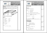
Determination of the resistance to normal<br />
forces and bending (example)<br />
G. Hanswille<br />
Univ.-Prof. Dr.-Ing.<br />
Institute for Steel and<br />
<strong>Composite</strong> Structures<br />
University of Wuppertal-Germany<br />
t f<br />
A s<br />
y<br />
h w<br />
b<br />
f yd N af<br />
N aw,c<br />
z pl<br />
0,85f cd<br />
- z<br />
t aw,c<br />
-<br />
w<br />
N s<br />
N M pl,N,Rd<br />
c<br />
z<br />
z s<br />
c<br />
V Ed<br />
z aw,t<br />
N<br />
z Ed<br />
N s<br />
(1-ρ)f f sd<br />
yd aw,t<br />
+<br />
N<br />
N s<br />
af<br />
Position of the plastic neutral axis:<br />
N + N −N<br />
= N<br />
c<br />
w<br />
aw,c<br />
pl<br />
aw,t<br />
cd<br />
w<br />
Ed<br />
pl<br />
yd<br />
w<br />
∑ N i = NEd<br />
( b − t )z 0,85 f + t z (1 − ρ)f<br />
− t (h − z ) (1 − ρ)f<br />
= N<br />
Plastic resistance to bending M pl,N,Rd in case of the<br />
simultaneously acting compression force N Ed and the<br />
vertical shear V Ed :<br />
M pl,N,Rd = Nc zc + Naw,c zaw,c + Naw,t zaw,t + Naf (hw + tf ) + 2Ns zs<br />
w<br />
pl<br />
yd<br />
Ed<br />
z<br />
pl<br />
NEd<br />
+ hw<br />
t<br />
=<br />
(b − t )0,85 f<br />
N<br />
N<br />
N<br />
N<br />
N<br />
aw,c<br />
aw,t<br />
af<br />
c<br />
s<br />
= b t<br />
= 2A<br />
f<br />
s<br />
w<br />
= z<br />
pl<br />
= (h<br />
w<br />
f<br />
= (b − t<br />
f<br />
t<br />
yd<br />
w<br />
sd<br />
w<br />
− z<br />
)z<br />
pl<br />
pl<br />
)<br />
cd<br />
t<br />
w<br />
w<br />
(1 − ρ)f<br />
+<br />
(1 − ρ)<br />
0,85<br />
f<br />
2t<br />
yd<br />
f<br />
cd<br />
w<br />
(1 − ρ)<br />
yd<br />
(1 − ρ)f<br />
f<br />
yd<br />
yd<br />
25
G. Hanswille<br />
Simplified determination of the interaction curve<br />
Univ.-Prof. Dr.-Ing.<br />
Institute for Steel and<br />
<strong>Composite</strong> Structures<br />
University of Wuppertal-Germany<br />
N pl,Rd<br />
N<br />
A<br />
A<br />
0,85f cd<br />
f sd<br />
f yd<br />
- -<br />
-<br />
N pl,Rd<br />
N pm, Rd<br />
N pm,<br />
Rd<br />
2<br />
B<br />
C<br />
Mpl,Rd<br />
D<br />
M max, Rd<br />
As a simplification, the interaction<br />
curve may be replaced by a polygonal<br />
diagram given by the points A to D.<br />
M<br />
B<br />
C<br />
D<br />
0,85f cd f sd<br />
f yd<br />
- - -<br />
h n<br />
+<br />
0,85f cd<br />
f sd<br />
f yd<br />
-<br />
-<br />
2hn<br />
z pl<br />
z pl<br />
z pl<br />
0,85f cd<br />
-<br />
f sd<br />
f yd<br />
-<br />
M = M<br />
+<br />
f yd<br />
+<br />
f yd<br />
+<br />
B,Rd<br />
M = M<br />
C,Rd<br />
N pm,Rd<br />
M = M<br />
f yd<br />
D,Rd<br />
pl,Rd<br />
pl,Rd<br />
max,Rd<br />
0,5 N pm,Rd<br />
26
Resistance at points A and D<br />
G. Hanswille<br />
Univ.-Prof. Dr.-Ing.<br />
Institute for Steel and<br />
<strong>Composite</strong> Structures<br />
University of Wuppertal-Germany<br />
Point A<br />
N pla,Rd<br />
N plc,Rd<br />
N pls,Rd<br />
yd<br />
Point D<br />
h c<br />
b c<br />
f cd<br />
- -<br />
-<br />
f sd<br />
M pls,Rd<br />
f yd<br />
0,5 M plc,Rd<br />
M pla,Rd<br />
-<br />
z si<br />
- f yd<br />
0,85 f cd +<br />
f sd<br />
+<br />
z si<br />
N<br />
M<br />
pl,Rd<br />
A,Rd<br />
= N<br />
= 0<br />
N<br />
M<br />
pla,Rd<br />
D,Rd<br />
D,Rd<br />
+ N<br />
= 0,5<br />
=<br />
t f<br />
M<br />
plc,Rd<br />
N<br />
plc,Rd<br />
max,Rd<br />
+ N<br />
b<br />
pls,Rd<br />
t w<br />
h<br />
M = M + M + 1 2<br />
max, Rd<br />
W pl,a<br />
W pl,s<br />
W pl,c<br />
pla,Rd<br />
pls,Rd<br />
M<br />
plc,Rd<br />
plastic section modulus of the<br />
structural steel section<br />
plastic section modulus of the crosssection<br />
of reinforcement<br />
plastic section modulus of the concrete<br />
section<br />
M<br />
M<br />
pls,Rd<br />
M<br />
pla,Rd<br />
plc,Rd<br />
= W<br />
= W<br />
= W<br />
pl,a<br />
pl,s<br />
pl,c<br />
f<br />
f<br />
yd<br />
sd<br />
=<br />
0,85 f<br />
[ ∑ A si z si ] f ys<br />
cd<br />
⎡b<br />
= ⎢<br />
⎢<br />
⎣<br />
c<br />
h<br />
4<br />
2<br />
⎡(h<br />
− 2tf<br />
)<br />
= ⎢<br />
⎢⎣<br />
4<br />
2<br />
c<br />
t<br />
w<br />
+ b t<br />
− W<br />
f<br />
pl,a<br />
(h − t<br />
− W<br />
f<br />
)<br />
pl,s<br />
⎤<br />
⎥<br />
⎥⎦<br />
f<br />
⎤<br />
⎥ 0,85 f<br />
⎥<br />
⎦<br />
cd<br />
27
Bending resistance at Point B (M pl,Rd )<br />
- 0,85f cd 0,85f cd - 0,85<br />
+ h f<br />
n<br />
cd<br />
f sd<br />
+<br />
+ +<br />
2 f sd -<br />
f yd<br />
+<br />
h n<br />
=<br />
+<br />
+<br />
-<br />
+ h n<br />
+ 2f yd<br />
N D,Rd<br />
M pln,Rd<br />
z pl h n<br />
Point D<br />
+ =<br />
M D,Rd<br />
N D,Rd<br />
-<br />
f yd<br />
+<br />
+<br />
f sd<br />
+<br />
G. Hanswille<br />
Univ.-Prof. Dr.-Ing.<br />
Institute for Steel and<br />
<strong>Composite</strong> Structures<br />
University of Wuppertal-Germany<br />
At point B is no resistance to<br />
compression forces. Therefore<br />
the resistance to compression<br />
forces at point D results from the<br />
additional cross-section zones in<br />
compression. With N D,Rd the<br />
depth h n and the position of the<br />
plastic neutral axis at point B can<br />
be determined. With the plastic<br />
bending moment M n,Rd resulting<br />
from the stress blocks within the<br />
depth h n the plastic resistance<br />
moment M pl,Rd at point B can be<br />
calculated by:<br />
M<br />
pl,Rd<br />
h n<br />
z pl<br />
=<br />
M<br />
D,Rd<br />
M pl,Rd<br />
−M<br />
Point B<br />
pln,Rd<br />
28
Plastic resistance moment at Point C<br />
G. Hanswille<br />
Univ.-Prof. Dr.-Ing.<br />
Institute for Steel and<br />
<strong>Composite</strong> Structures<br />
University of Wuppertal-Germany<br />
- 0,85 f cd<br />
-<br />
- 2h n<br />
+<br />
+<br />
-<br />
2 f sd<br />
+ 2h n =<br />
f yd<br />
+ +<br />
f sd<br />
0,85f cd 0,85f cd<br />
2f yd<br />
- - 2h -<br />
+<br />
n<br />
f yd<br />
+<br />
fsd<br />
+<br />
+<br />
+<br />
The bending resistance at point C<br />
is the same as the bending<br />
resistance at point B.<br />
M C,Rd = M pl,Rd<br />
The normal force results from the<br />
stress blocks in the zone 2h n.<br />
N C,Rd =2N D,Rd =N cpl,Rd =N pm,Rd<br />
Point B<br />
Point C<br />
h n<br />
z pl<br />
M pl,Rd<br />
+ =<br />
2h n<br />
N C,Rd<br />
2h n<br />
N c,Rd<br />
M c,Rd<br />
29
G. Hanswille<br />
Univ.-Prof. Dr.-Ing.<br />
Institute for Steel and<br />
<strong>Composite</strong> Structures<br />
University of Wuppertal-Germany<br />
Part 4:<br />
Simplified design method<br />
30
Simplified Method<br />
G. Hanswille<br />
Univ.-Prof. Dr.-Ing.<br />
Institute for Steel and<br />
<strong>Composite</strong> Structures<br />
University of Wuppertal-Germany<br />
Methods of verification acc. to the simplified method<br />
Axial<br />
compression<br />
Design based on the<br />
European buckling curves<br />
κ<br />
λ K<br />
Design based on second order<br />
analysis with equivalent geometrical<br />
bow imperfections<br />
w o<br />
Resistance<br />
of member<br />
in combined<br />
compression<br />
and bending<br />
Design based on second order<br />
analysis with equivalent geometrical<br />
bow imperfections<br />
w o<br />
31
Scope of the simplified method<br />
G. Hanswille<br />
Univ.-Prof. Dr.-Ing.<br />
Institute for Steel and<br />
<strong>Composite</strong> Structures<br />
University of Wuppertal-Germany<br />
double symmetrical cross-section<br />
uniform cross-sections over the member length with rolled,<br />
cold-formed or welded steel sections<br />
steel contribution ratio<br />
A<br />
0 ,2 ≤ δ ≤ 0,9 δ =<br />
N<br />
relative slenderness<br />
Npl,Rk<br />
λ = ≤ 2,0<br />
N<br />
cr<br />
yd<br />
pl,Rd<br />
longitudinal reinforcement ratio<br />
a<br />
f<br />
0 ,3% ≤ ρ ≤ 6,0 % ρ =<br />
s<br />
s<br />
A<br />
A<br />
s<br />
c<br />
the ratio of the depth to the width of the composite crosssection<br />
should be within the limits 0,2 and 5,0<br />
32
Effects of creep of concrete<br />
G. Hanswille<br />
Univ.-Prof. Dr.-Ing.<br />
Institute for Steel and<br />
<strong>Composite</strong> Structures<br />
University of Wuppertal-Germany<br />
2000<br />
1500<br />
Load<br />
F [kN]<br />
F<br />
F u = 2022 kN<br />
short term test<br />
F u = 1697 kN<br />
long term test<br />
e<br />
w t<br />
w o<br />
L = 800 cm<br />
The horizontal deflection and<br />
the second order bending<br />
moments increase under<br />
permanent loads due to creep of<br />
concrete. This leads to a<br />
reduction of the ultimate load.<br />
1000<br />
30 cm<br />
500<br />
F v = 534 kN<br />
permanent<br />
load<br />
30 cm<br />
e=3 cm<br />
The effects of creep of<br />
concrete are taken into<br />
account in design by a<br />
reduced flexural stiffness of<br />
the composite cross-section.<br />
0<br />
20 40 60 80 100<br />
deflection w [mm]<br />
33
Effects of creep on the flexural stiffness<br />
G. Hanswille<br />
Univ.-Prof. Dr.-Ing.<br />
Institute for Steel and<br />
<strong>Composite</strong> Structures<br />
University of Wuppertal-Germany<br />
The effects of creep of concrete are<br />
taken into account by an effective<br />
modulus of elasticity of concrete<br />
E<br />
c,eff<br />
E<br />
=<br />
N<br />
1+<br />
N<br />
G,Ed<br />
Ed<br />
cm<br />
ϕ(t,t<br />
notional size of the cross-section for<br />
the determination of the creep<br />
coefficient ϕ(t,t o )<br />
h<br />
o =<br />
2 A<br />
U<br />
c<br />
effective perimeter U of the crosssection<br />
b<br />
b<br />
o<br />
)<br />
E cm<br />
N Ed<br />
N G,Ed<br />
ϕ(t,t o )<br />
Secant modulus of concrete<br />
total design normal force<br />
part of the total normal force that is<br />
permanent<br />
creep coefficient as a function of the time at<br />
loading t o , the time t considered and the<br />
notional size of the cross-section<br />
In case of concrete filled hollow section the drying of the<br />
concrete is significantly reduced by the steel section. A<br />
good estimation of the creep coefficient can be<br />
achieved, if 25% of that creep coefficient is used, which<br />
results from a cross-section, where the notional size h o<br />
is determined neglecting the steel hollow section.<br />
h<br />
h<br />
ϕ t,eff<br />
= 0,25 ϕ(t,t o<br />
)<br />
U = 2(b + h) U ≈2h<br />
+ 0,5b<br />
34
Verification for axial compression with the<br />
European buckling curves<br />
G. Hanswille<br />
Univ.-Prof. Dr.-Ing.<br />
Institute for Steel and<br />
<strong>Composite</strong> Structures<br />
University of Wuppertal-Germany<br />
cross-section<br />
buckling about<br />
strong axis<br />
ν = 0,85<br />
buckling about<br />
weak axis<br />
ν = 0,85<br />
ρ s ≤3% ν = 1,00<br />
3%<br />
ρ s ≤ 6%<br />
ν = 1,00<br />
buckling<br />
curve<br />
b<br />
c<br />
a<br />
cr<br />
0,2 0,6 1,0 1,4 1,8<br />
< b<br />
N<br />
Verification:<br />
Ed ≤ 1,0<br />
NRd<br />
ν = 1,00<br />
ν<br />
= 0,85<br />
b<br />
b<br />
1,0<br />
0,8<br />
0,6<br />
0,4<br />
0,2<br />
N<br />
N<br />
χ =<br />
N<br />
pl,Rd<br />
Rd<br />
pl,Rd<br />
Design value of<br />
resistance<br />
= A<br />
a<br />
f<br />
yd<br />
b<br />
+<br />
a<br />
N<br />
A<br />
c<br />
= χ<br />
Rd N pl,Rd<br />
s<br />
f<br />
sd<br />
λ<br />
=<br />
+ ν A<br />
N<br />
N<br />
c<br />
pl,Rk<br />
cr<br />
λ =<br />
f<br />
cd<br />
≤<br />
2,0<br />
Npl,k<br />
N<br />
35
Relative slenderness<br />
G. Hanswille<br />
Univ.-Prof. Dr.-Ing.<br />
Institute for Steel and<br />
<strong>Composite</strong> Structures<br />
University of Wuppertal-Germany<br />
f<br />
cd<br />
f<br />
=<br />
γ<br />
ck<br />
c<br />
ν = 0,85<br />
relative slenderness:<br />
λ<br />
=<br />
N<br />
pl,Rk<br />
N<br />
cr<br />
≤<br />
2,0<br />
characteristic value of the plastic<br />
resistance to compressive forces<br />
N = A f + A ν f + A<br />
pl,Rk<br />
a<br />
yk<br />
c<br />
ck<br />
s<br />
f<br />
sk<br />
f<br />
cd<br />
f<br />
=<br />
γ<br />
ck<br />
c<br />
ν = 1,00<br />
elastic critical normal force<br />
N<br />
cr<br />
π<br />
=<br />
2<br />
(EJ)<br />
( βL)<br />
eff<br />
2<br />
β - buckling length factor<br />
effective flexural stiffness<br />
( EJ) eff = (EaJa<br />
+ Ke<br />
Ec,eff<br />
Jc<br />
+ EsJs<br />
)<br />
K e =0,6<br />
36
Verification for combined<br />
compression and bending<br />
G. Hanswille<br />
Univ.-Prof. Dr.-Ing.<br />
Institute for Steel and<br />
<strong>Composite</strong> Structures<br />
University of Wuppertal-Germany<br />
N pl,Rd<br />
N Ed<br />
N<br />
w o<br />
equivalent<br />
geometrical bow<br />
imperfection<br />
Verification<br />
max M<br />
Ed<br />
≤ M<br />
Rd<br />
= α<br />
M<br />
α M<br />
= 0,9 for S235 and S355<br />
μ<br />
M<br />
pl,Rd<br />
w o<br />
α M<br />
= 0,8 for S420 and S460<br />
α M<br />
μ M pl,Rd<br />
M pl,N,Rd<br />
M<br />
bending moments taking into<br />
account second order effects:<br />
f yd<br />
(1-ρ) f yd<br />
+<br />
-<br />
M Rd<br />
0,85f cd<br />
f sd<br />
M pl,Rd<br />
V Ed<br />
M pl,N Rd<br />
N Ed<br />
The factor α M takes into account the<br />
difference between the full plastic and the<br />
elasto-plastic resistance of the cross-section<br />
resulting from strain limitations for concrete.<br />
-<br />
max M<br />
N<br />
cr<br />
(EI)<br />
with<br />
π<br />
=<br />
Ed<br />
2<br />
eff,II<br />
K<br />
= N<br />
(E J)<br />
β<br />
2<br />
= K<br />
e,II<br />
L<br />
Ed<br />
w<br />
eff,II<br />
2<br />
o<br />
=<br />
(E<br />
a<br />
J<br />
0,5<br />
o<br />
a<br />
1<br />
N<br />
1−<br />
N<br />
+<br />
K<br />
K<br />
e<br />
o<br />
Ed<br />
Effective flexural stiffness<br />
cr<br />
E<br />
c,eff<br />
= 0,9<br />
J<br />
c<br />
+<br />
E<br />
s<br />
J<br />
s<br />
)<br />
37
Equivalent initial bow imperfections<br />
G. Hanswille<br />
Univ.-Prof. Dr.-Ing.<br />
Institute for Steel and<br />
<strong>Composite</strong> Structures<br />
University of Wuppertal-Germany<br />
Buckling curve<br />
a b c<br />
3%<br />
< ρ s ≤ 6%<br />
ρ s ≤3%<br />
Member imperfection<br />
w o = L/300 w o = L/200 w o = L/150<br />
38
Imperfections for global analysis of frames<br />
G. Hanswille<br />
Univ.-Prof. Dr.-Ing.<br />
Institute for Steel and<br />
<strong>Composite</strong> Structures<br />
University of Wuppertal-Germany<br />
sway imperfection<br />
Global initial sway imperfection acc. to EN 1993-1-1:<br />
N Ed,1<br />
N Ed,2<br />
φ<br />
=<br />
φ<br />
o<br />
α<br />
m<br />
α<br />
h<br />
h<br />
φ φ Φ o basic value with Φ o = 1/200<br />
α h<br />
reduction factor for the height h in [m]<br />
α<br />
h<br />
=<br />
2<br />
h<br />
but<br />
2<br />
3<br />
≤ α<br />
h<br />
≤1,0<br />
equivalent forces<br />
α m<br />
reduction factor for the number of <strong>columns</strong> in a row<br />
Φ N Ed,1<br />
N Ed,1<br />
N Ed,2<br />
Φ N Ed,2<br />
α<br />
m<br />
=<br />
0,5<br />
⎢<br />
⎡ 1 +<br />
⎣<br />
1<br />
m<br />
⎤<br />
⎥<br />
⎦<br />
Φ N Ed,1<br />
Φ N Ed,2<br />
m is the number of <strong>columns</strong> in a row including only<br />
those <strong>columns</strong> which carry a vertical load N Ed not<br />
less than 50% of the average value of the column<br />
in a vertical plane considered.<br />
39
Frames sensitive against second order effects<br />
G. Hanswille<br />
Univ.-Prof. Dr.-Ing.<br />
Institute for Steel and<br />
<strong>Composite</strong> Structures<br />
University of Wuppertal-Germany<br />
N Ed,1<br />
imperfections<br />
λ > 0,5<br />
N<br />
N<br />
pl,Rk<br />
L Ed, 2<br />
1<br />
φ 1<br />
φ 2<br />
N Ed,2<br />
L 2<br />
Within a global analysis, member imperfections in<br />
composite compression members may be<br />
neglected where first-order analysis may be<br />
used. Where second-order analysis should be<br />
used, member imperfections may be neglected<br />
within the global analysis if:<br />
λ<br />
≤ 0,5<br />
N<br />
N<br />
pl,Rk<br />
Ed,1<br />
w 0<br />
λ<br />
≤<br />
0,5<br />
N<br />
N<br />
pl,Rk<br />
Ed, i<br />
N Ed,1<br />
N Ed,2<br />
w<br />
4<br />
o N<br />
L2<br />
N Ed,1 φ N Ed,2 φ 2<br />
1<br />
equivalent<br />
w o<br />
forces<br />
q=8 N<br />
2 Ed, 2<br />
N L<br />
Ed,1 φ 1 2<br />
N Ed,2 φ 2<br />
w<br />
4<br />
L<br />
Ed,2<br />
o NEd,2<br />
2<br />
N<br />
λ =<br />
cr<br />
π<br />
=<br />
N<br />
2<br />
pl,Rk<br />
N<br />
cr<br />
(EJ)<br />
L<br />
2<br />
i<br />
eff<br />
( EJ) eff = (EaJa<br />
+ 0,6E c,eff Jc<br />
+ EsJs<br />
)<br />
40
Second order analysis<br />
G. Hanswille<br />
Univ.-Prof. Dr.-Ing.<br />
Institute for Steel and<br />
<strong>Composite</strong> Structures<br />
University of Wuppertal-Germany<br />
N<br />
r M R<br />
r M R<br />
Bending moments including second order effects:<br />
⎛ r sin ε (1− ξ)<br />
+ sin ε ξ ⎞ ⎛ cos ε (0,5 − ξ)<br />
⎞<br />
M(<br />
ξ)<br />
= MR<br />
⎜<br />
⎟ + Mo<br />
⎜<br />
−1⎟<br />
⎝ sin ε ⎠ ⎝ cos ( ε / 2) ⎠<br />
EJ<br />
V<br />
z<br />
M ε⎛<br />
r cos ε (1− ξ)<br />
+ cos ε ξ ⎞ ⎛ sin ε (0,5 − ξ)<br />
⎞<br />
( ξ)<br />
=<br />
R<br />
⎜<br />
⎟ + Mo<br />
⎜<br />
−1⎟<br />
L ⎝ sin ε ⎠ ⎝ cos ( ε / 2) ⎠<br />
q<br />
L<br />
ζ M<br />
ζ<br />
M max<br />
M<br />
o<br />
=<br />
(q L<br />
2<br />
+ 8Nw<br />
o<br />
1<br />
)<br />
2<br />
ε<br />
ε=L<br />
Maximum bending moment at the point ξ M :<br />
N<br />
(E J)<br />
Ed<br />
eff,II<br />
⎛<br />
⎜<br />
⎝<br />
dM<br />
=<br />
dξ<br />
⎞<br />
0⎟<br />
⎠<br />
M<br />
max<br />
=<br />
[ 0,5M(1 + r) + M ]<br />
o<br />
2<br />
1+<br />
c<br />
cos(0,5 ε)<br />
−<br />
M<br />
0<br />
w o<br />
M R<br />
M R<br />
c =<br />
M (r −1)<br />
M(1+<br />
r) + 2M<br />
o<br />
1<br />
tan(0,5ε<br />
)<br />
ξ<br />
M<br />
= 0,5<br />
+<br />
arctan<br />
ε<br />
c<br />
41
Simplified calculation of second order effects<br />
G. Hanswille<br />
Univ.-Prof. Dr.-Ing.<br />
Institute for Steel and<br />
<strong>Composite</strong> Structures<br />
University of Wuppertal-Germany<br />
4,0<br />
3,0<br />
k<br />
r=1,0<br />
r=0,5<br />
r=0<br />
r M R<br />
N<br />
EJ<br />
r M R<br />
Exact solution:<br />
M<br />
max<br />
= 0,5M<br />
R<br />
r −1<br />
1<br />
c =<br />
1+<br />
r tan(0,5ε<br />
)<br />
2<br />
1+<br />
c<br />
(1+<br />
r)<br />
cos(0,5 ε)<br />
2,0<br />
r= - 0,5<br />
L<br />
ζ<br />
ζ M<br />
M max<br />
ξ<br />
M<br />
= 0,5 +<br />
arctan<br />
ε<br />
c<br />
ε=L<br />
N<br />
(E J)<br />
Ed<br />
eff,II<br />
M R<br />
simplified solution:<br />
1,0<br />
exact method<br />
simplified method<br />
N<br />
M R<br />
k =<br />
M<br />
M<br />
max<br />
R<br />
β<br />
=<br />
N<br />
1−<br />
N<br />
Ed<br />
cr<br />
β = 0 ,66 +<br />
β ≥<br />
0,44<br />
0,44r<br />
0,25 0,50 0,75 1,00<br />
N cr<br />
42
Background of the member imperfections<br />
G. Hanswille<br />
Univ.-Prof. Dr.-Ing.<br />
Institute for Steel and<br />
<strong>Composite</strong> Structures<br />
University of Wuppertal-Germany<br />
N Rd<br />
N<br />
ε =L<br />
N<br />
(EJ)<br />
Rd<br />
Bending moment based on second<br />
order analysis:<br />
N Ed<br />
=N Rd<br />
eff,II<br />
= 8 wo<br />
(EJ) eff,II ⎡ 1 ⎤<br />
M<br />
⎢ −<br />
2<br />
⎥<br />
L ⎣cos(<br />
ε / 2)<br />
1<br />
⎦<br />
wo Resistance to axial compression<br />
μ M pl,Rd<br />
based on the European buckling<br />
curves:<br />
N<br />
= χ<br />
Rd N pl,Rd<br />
M Rd<br />
M pl,Rd<br />
M<br />
Bending resistance:<br />
M<br />
Rd<br />
= α<br />
M<br />
μ<br />
M<br />
pl,Rd<br />
The initial bow imperfections were<br />
recalculated from the resistance to<br />
compression calculated with the<br />
European buckling curves.<br />
Determination of the equivalent bow<br />
imperfection:<br />
w<br />
o<br />
α<br />
=<br />
8(EJ)<br />
M<br />
eff,II<br />
μ<br />
d<br />
M<br />
pl,Rd<br />
L<br />
2<br />
⎡ 1<br />
⎢<br />
⎣1−cos(<br />
ε / 2)<br />
⎤<br />
−1⎥<br />
⎦<br />
43
Geometrical bow imperfections –<br />
comparison with European buckling<br />
curves for axial compression<br />
G. Hanswille<br />
Univ.-Prof. Dr.-Ing.<br />
Institute for Steel and<br />
<strong>Composite</strong> Structures<br />
University of Wuppertal-Germany<br />
j<br />
500<br />
400<br />
1<br />
N ( )<br />
δ =<br />
δ N (w )<br />
Rd κ<br />
Rd<br />
o<br />
1,2<br />
1<br />
1,1<br />
2<br />
3<br />
1<br />
2<br />
3<br />
C20/S235<br />
C40/S355<br />
C60/S355<br />
300<br />
200<br />
j =<br />
L<br />
w o<br />
1,0 2,0<br />
2<br />
3<br />
λ<br />
The initial bow imperfection is a<br />
function of the related slenderness<br />
and the resistance of cross-sections.<br />
In Eurocode 4 constant values for w 0<br />
are used.<br />
1,0<br />
0,9<br />
0,8<br />
w o = l/300<br />
0,4 0,8 1,2 1,6 2,0<br />
The use of constant values for w o leads to<br />
maximum differences of 5% in<br />
comparison with the calculation based on<br />
the European buckling curves.<br />
λ<br />
44
Comparison of the simplified method with nonlinear<br />
calculations for combined compression<br />
and bending<br />
G. Hanswille<br />
Univ.-Prof. Dr.-Ing.<br />
Institute for Steel and<br />
<strong>Composite</strong> Structures<br />
University of Wuppertal-Germany<br />
1,0<br />
0,8<br />
N<br />
N pl,Rd<br />
Resistance as a function of the<br />
related slenderness<br />
Plastic cross-section<br />
resistance<br />
λ<br />
=<br />
N<br />
pl,Rk<br />
N<br />
cr<br />
λ k = 0,50<br />
λ k = 1,00<br />
λ k = 1,50<br />
0,6<br />
λ k = 2,00<br />
0,4<br />
general method<br />
0,2<br />
simplified method<br />
M<br />
0,2 0,4 0,6 0,8 1,0<br />
M pl,Rd<br />
45
Resistance to combined compression<br />
and biaxial bending<br />
G. Hanswille<br />
Univ.-Prof. Dr.-Ing.<br />
Institute for Steel and<br />
<strong>Composite</strong> Structures<br />
University of Wuppertal-Germany<br />
Interaction<br />
M z , N<br />
μ dz<br />
μz,Ed<br />
N<br />
N pl,Rd<br />
μ y, Ed<br />
N<br />
N<br />
pl,Rd<br />
μ dy<br />
Ed<br />
B<br />
Interaction<br />
M y , N<br />
Interaction<br />
M y , M z , N Ed<br />
The resistance is given by a threedimensional<br />
interaction relation. For<br />
simplification a linear interaction<br />
between the points A and B is used.<br />
M<br />
M<br />
M<br />
y,Rd<br />
z,Rd<br />
y,Ed<br />
M<br />
z,Ed<br />
(N<br />
(N<br />
Ed<br />
Ed<br />
= μ<br />
= μ<br />
)<br />
= μ<br />
) = μ<br />
y,Ed<br />
z,Ed<br />
M<br />
dy<br />
dz<br />
M<br />
M<br />
M<br />
y,Rd<br />
y,Rd<br />
pl,y,Rd<br />
pl,y,Rd<br />
A<br />
Approximation:<br />
μy,Ed<br />
μz,Ed<br />
+ ≤ 1,0<br />
μ μ<br />
dy<br />
dz<br />
approximation for the<br />
interaction curve:<br />
M<br />
M<br />
z<br />
pl,z,Rd<br />
Interaction<br />
M y , M z<br />
M<br />
M<br />
y<br />
pl,y, Rd<br />
μ<br />
μ<br />
μ<br />
y,Ed<br />
dy<br />
dy<br />
M<br />
M<br />
μ<br />
+<br />
μ<br />
y,Ed<br />
z,Ed<br />
dz<br />
pl,y,Rd<br />
≤ 1,0<br />
+<br />
μ<br />
dz<br />
M<br />
M<br />
z,Ed<br />
pl,z,Rd<br />
≤ 1,0<br />
46
Verification in case of compression an biaxial<br />
bending<br />
G. Hanswille<br />
Univ.-Prof. Dr.-Ing.<br />
Institute for Steel and<br />
<strong>Composite</strong> Structures<br />
University of Wuppertal-Germany<br />
For both axis a separate verification<br />
is necessary.<br />
μ<br />
μ<br />
dy<br />
dy<br />
M<br />
M<br />
M<br />
M<br />
y,Ed<br />
pl,y,Rd<br />
y,Ed<br />
pl,y,Rd<br />
≤<br />
+<br />
α<br />
μ<br />
M<br />
dz<br />
M<br />
M<br />
z,Ed<br />
μ<br />
dz<br />
pl,y,Rd<br />
M<br />
M<br />
z,Ed<br />
pl,y,Rd<br />
Verification for the interaction of biaxial<br />
bending.<br />
≤ 1,0<br />
Imperfections should be considered<br />
only in the plane in which failure is<br />
expected to occur. If it is not evident<br />
which plane is the most critical,<br />
checks should be made for both<br />
planes.<br />
≤<br />
α<br />
M<br />
N<br />
N pl,Rd<br />
N<br />
N<br />
N<br />
N pl,Rd<br />
N<br />
N<br />
Ed<br />
pl,Rd<br />
Ed<br />
pl,Rd<br />
μ dy<br />
μ dz<br />
α M = 0,9 for S235 and S355<br />
α M = 0,8 for S420 and S460<br />
M<br />
M<br />
M<br />
y,Rd<br />
pl,y,Rd<br />
M<br />
z,Rd<br />
pl,z,Rd<br />
47
G. Hanswille<br />
Univ.-Prof. Dr.-Ing.<br />
Institute for Steel and<br />
<strong>Composite</strong> Structures<br />
University of Wuppertal-Germany<br />
Part 5:<br />
Special aspects of <strong>columns</strong> with inner core profiles<br />
48
<strong>Composite</strong> <strong>columns</strong> – General Method<br />
G. Hanswille<br />
Univ.-Prof. Dr.-Ing.<br />
Institute for Steel and<br />
<strong>Composite</strong> Structures<br />
University of Wuppertal-Germany<br />
Commerzbank Frankfurt<br />
Millennium Tower Vienna<br />
Highlight Center<br />
Munich<br />
New railway station in Berlin<br />
(Lehrter Bahnhof)<br />
49
<strong>Composite</strong> <strong>columns</strong> with concrete filled<br />
tubes and steel cores – special effects<br />
G. Hanswille<br />
Univ.-Prof. Dr.-Ing.<br />
Institute for Steel and<br />
<strong>Composite</strong> Structures<br />
University of Wuppertal-Germany<br />
Resistance based on stress blocks (plastic<br />
resistance)<br />
tube core concrete<br />
f y f y f c<br />
M<br />
N<br />
Non linear resistance with strain limitation for concrete<br />
strains ε<br />
f y f y<br />
f c<br />
M<br />
α<br />
M<br />
=<br />
M<br />
μ M<br />
Rd<br />
pl,Rd<br />
Cross-sections with<br />
massive inner cores have<br />
a very high plastic shape<br />
factor and the cores can<br />
have very high residual<br />
stresses. Therefore these<br />
<strong>columns</strong> can not be<br />
design with the simplified<br />
method according to EN<br />
1944-1-1.<br />
σ ED<br />
N<br />
r<br />
50
Residual stresses and distribution of the<br />
yield strength<br />
G. Hanswille<br />
Univ.-Prof. Dr.-Ing.<br />
Institute for Steel and<br />
<strong>Composite</strong> Structures<br />
University of Wuppertal-Germany<br />
300<br />
σ ED [N/mm 2 ]<br />
f yk<br />
distribution of yield strenght<br />
f y (r)<br />
250<br />
200<br />
150<br />
100<br />
U<br />
A<br />
=<br />
π<br />
= π<br />
d k<br />
2<br />
d<br />
k<br />
/ 4<br />
d k<br />
r k<br />
f yk – characteristic value<br />
of the yield strenght<br />
fy(r)<br />
⎛<br />
= 0,95 + 0,1 ⎜<br />
fyk<br />
⎝<br />
r<br />
r<br />
k<br />
2<br />
⎞<br />
⎟<br />
⎠<br />
50<br />
U/A [1/m]<br />
10 20 30 40 50<br />
d K<br />
[mm]<br />
residual stresses:<br />
400 200 130<br />
100<br />
80<br />
d K<br />
d<br />
σ ED<br />
σ<br />
E<br />
(r) = σ<br />
ED<br />
⎡<br />
2r<br />
⎢1−<br />
⎢<br />
⎣<br />
r<br />
2<br />
2<br />
K<br />
⎤<br />
⎥<br />
⎥<br />
⎦<br />
r, r k<br />
51
General method – Finite Element Model<br />
G. Hanswille<br />
Univ.-Prof. Dr.-Ing.<br />
Institute for Steel and<br />
<strong>Composite</strong> Structures<br />
University of Wuppertal-Germany<br />
load introduction<br />
stresses in the tube<br />
initial bow imperfection<br />
cross-section<br />
stresses in concrete<br />
52
G. Hanswille<br />
Univ.-Prof. Dr.-Ing.<br />
Institute for Steel and<br />
<strong>Composite</strong> Structures<br />
University of Wuppertal-Germany<br />
Part 6:<br />
Load introduction and<br />
longitudinal shear<br />
53
Load introduction over the steel section<br />
G. Hanswille<br />
Univ.-Prof. Dr.-Ing.<br />
Institute for Steel and<br />
<strong>Composite</strong> Structures<br />
University of Wuppertal-Germany<br />
N Ed<br />
load introduction by headed studs within the<br />
load introduction length L E<br />
P D L E < 2,0 d<br />
N c,Ed<br />
N a,Ed<br />
d<br />
A a<br />
N s,Ed<br />
A s<br />
A c<br />
L E<br />
⎧ 2d<br />
≤ ⎨<br />
⎩L / 3<br />
d minimum transverse dimension of<br />
the cross-section<br />
L<br />
member length of the column<br />
sectional forces of the cross-section :<br />
Npl,a<br />
Npl,s<br />
N a,Ed = NEd<br />
Ns,Ed<br />
= NEd<br />
Nc,Ed<br />
= N<br />
N<br />
N<br />
pl,Rd<br />
pl,Rd<br />
required number of studs n resulting from the<br />
sectional forces N Ed,c<br />
+ N Ed,s<br />
:<br />
V<br />
L,Ed<br />
⎡ Npl,a<br />
⎥ ⎥ ⎤<br />
= Nc,Ed<br />
+ Ns,Ed<br />
= NEd<br />
⎢1<br />
−<br />
⎢⎣<br />
Npl,<br />
Rd ⎦<br />
P Rd – design resistance of studs<br />
V = nP<br />
L,Rd<br />
Rd<br />
Ed<br />
N<br />
N<br />
pl,c<br />
pl,Rd<br />
54
G. Hanswille<br />
Load introduction for combined comression and<br />
Univ.-Prof. Dr.-Ing.<br />
Institute for Steel and<br />
bending<br />
<strong>Composite</strong> Structures<br />
University of Wuppertal-Germany<br />
sectional forces due to N Ed<br />
und M Ed<br />
sectional forces based on plastic theory<br />
M Ed<br />
N Ed<br />
M Rd = Ma,Rd<br />
+ Mc+ s,Rd NRd<br />
= Na,Rd<br />
+ Nc+<br />
s,Rd<br />
N<br />
z pl<br />
-<br />
M a;Rd<br />
0,85f<br />
f cd<br />
sd<br />
M<br />
M Rd<br />
-<br />
c,+s,Rd<br />
+ =<br />
N pl,Rd<br />
1,0<br />
f yd<br />
+<br />
N a,Rd<br />
f sd<br />
N c+s,Rd<br />
N Rd<br />
N a,Ed<br />
N c,Ed + N s,Ed<br />
M c,Ed + M s,Ed<br />
M a,Ed<br />
N<br />
N<br />
N<br />
N<br />
Rd<br />
pl,Rd<br />
Ed<br />
pl, Rd<br />
E d<br />
R d<br />
E<br />
R<br />
d<br />
d<br />
N<br />
=<br />
N<br />
M<br />
M pl,Rd<br />
a,Ed<br />
a,Rd<br />
R<br />
=<br />
d<br />
M<br />
M<br />
=<br />
a,Ed<br />
a,Rd<br />
⎛<br />
⎜<br />
M<br />
⎝<br />
M<br />
=<br />
Ed<br />
pl,Rd<br />
N<br />
N<br />
⎞<br />
⎟<br />
⎠<br />
c+<br />
s,Ed<br />
c+<br />
s,Rd<br />
2<br />
⎛ N<br />
+ ⎜<br />
⎝<br />
N<br />
Ed<br />
=<br />
pl,Rd<br />
⎞<br />
⎟<br />
⎠<br />
M<br />
M<br />
2<br />
c+<br />
s,Ed<br />
c+<br />
s,Rd<br />
M<br />
M<br />
Ed<br />
pl,Rd<br />
M<br />
M<br />
Rd<br />
pl,Rd<br />
1,0<br />
E<br />
d<br />
=<br />
⎛<br />
⎜<br />
M<br />
⎝<br />
M<br />
Rd<br />
pl,Rd<br />
⎞<br />
⎟<br />
⎠<br />
2<br />
⎛ N<br />
+ ⎜<br />
⎝<br />
N<br />
Rd<br />
pl,Rd<br />
⎞<br />
⎟<br />
⎠<br />
2<br />
55
Load introduction – Example<br />
G. Hanswille<br />
Univ.-Prof. Dr.-Ing.<br />
Institute for Steel and<br />
<strong>Composite</strong> Structures<br />
University of Wuppertal-Germany<br />
sectional forces based on stress blocks:<br />
f yd<br />
f f cd sd -N s,i<br />
Nc<br />
+ s,Rd = Nc<br />
+ ∑Nsi<br />
- M -N<br />
a;Rd<br />
Z<br />
z pl - c s<br />
M c,+s,Rd Mc<br />
+ s,Rd = Nc<br />
zc<br />
+ ∑Nsi<br />
zsi<br />
z<br />
N c<br />
a,Rd<br />
Z s<br />
-N<br />
+<br />
c+s,Rd<br />
f sd N s,i<br />
shear forces of studs based on elastic theory shear forces of studs based on plastic theory<br />
2<br />
2<br />
⎡N<br />
c s,Ed M ⎤ ⎡<br />
c s,Ed M ⎤<br />
c s,Ed<br />
Nc<br />
+ s,Ed Mc<br />
+ s,Ed<br />
maxPEd<br />
⎢<br />
+ +<br />
xi⎥<br />
⎢<br />
+<br />
=<br />
+<br />
+ zi⎥<br />
max PEd<br />
= +<br />
⎢ n<br />
2<br />
2<br />
r ⎥ ⎢<br />
n eh<br />
0,5 n<br />
i<br />
r ⎥<br />
⎣<br />
∑ ⎦ ⎣ ∑<br />
i ⎦<br />
n – number of<br />
P Ed (N)<br />
z i<br />
x studs within the<br />
P i<br />
ed,v r i<br />
load introduction<br />
e h<br />
P length<br />
ed,h P Ed (M)<br />
N M<br />
c+s,Ed M c+s,Ed<br />
c+s,Ed<br />
N c+s,Ed<br />
56
Shear resistance of stud connectors welded<br />
to the web of partially encased I-Sections<br />
G. Hanswille<br />
Univ.-Prof. Dr.-Ing.<br />
Institute for Steel and<br />
<strong>Composite</strong> Structures<br />
University of Wuppertal-Germany<br />
P Rd<br />
D c<br />
µP Rd<br />
/ 2<br />
µP Rd<br />
/ 2<br />
V = P + V<br />
L,Rd<br />
V<br />
LR,Rd<br />
Rd<br />
= μ<br />
P<br />
LR, Rd<br />
Rd<br />
Where stud connectors are attached to the web of a fully or<br />
partially concrete encased steel I-section or a similar<br />
section, account may be taken of the frictional forces that<br />
develop from the prevention of lateral expansion of the<br />
concrete by the adjacent steel flanges. This resistance may<br />
be added to the calculated resistance of the shear<br />
connectors. The additional resistance may be assumed to<br />
be on each flange and each horizontal row of studs, where μ<br />
is the relevant coefficient of friction that may be assumed.<br />
For steel sections without painting, μ may be taken as 0,5.<br />
P Rd<br />
is the resistance of a single stud.<br />
57
Shear resistance of stud connectors welded<br />
to the web of partially encased I-Sections<br />
G. Hanswille<br />
Univ.-Prof. Dr.-Ing.<br />
Institute for Steel and<br />
<strong>Composite</strong> Structures<br />
University of Wuppertal-Germany<br />
P Rd<br />
P Rd<br />
P Rd<br />
P Rd<br />
P Rd P Rd<br />
V LR,Rd /2<br />
< 300 < 400 < 600<br />
V<br />
L,Rd<br />
=<br />
nP<br />
Rd<br />
+ V<br />
LR,Rd<br />
V<br />
LR,Rd<br />
=<br />
μ<br />
P<br />
Rd<br />
P Rd = min<br />
P<br />
P<br />
Rd,1<br />
Rd,2<br />
= 0,29 α<br />
= 0,8 ⋅ f<br />
u<br />
d<br />
2<br />
⎛<br />
⎜<br />
π d<br />
⎝ 4<br />
2<br />
f<br />
ck<br />
⎞<br />
⎟<br />
1<br />
⎠ γv<br />
E<br />
cm<br />
1<br />
γ<br />
v<br />
In absence of better information from tests, the clear distance between<br />
the flanges should not exceed the values given above.<br />
58
Shear resistance of stud connectors welded<br />
to the web of partially encased I-sections<br />
G. Hanswille<br />
Univ.-Prof. Dr.-Ing.<br />
Institute for Steel and<br />
<strong>Composite</strong> Structures<br />
University of Wuppertal-Germany<br />
F [kN]<br />
F<br />
F<br />
F<br />
F<br />
3500<br />
3000<br />
2500<br />
2000<br />
test series S1<br />
test series S2<br />
1500<br />
test S3/3<br />
1000<br />
test S1/3<br />
500<br />
w [mm]<br />
0<br />
0 2 4 6 8 10 12 14 16<br />
59
Load introduction – longitudinal shear<br />
forces in concrete<br />
G. Hanswille<br />
Univ.-Prof. Dr.-Ing.<br />
Institute for Steel and<br />
<strong>Composite</strong> Structures<br />
University of Wuppertal-Germany<br />
N Ed<br />
b c<br />
D c<br />
D c<br />
θ<br />
Z s<br />
Z s<br />
Z θ<br />
s<br />
D c<br />
N Ed<br />
Longitudinal shear force in section I-I:<br />
V<br />
L,Ed<br />
=<br />
N<br />
Ed<br />
⎡ N<br />
⎢1<br />
−<br />
⎢⎣<br />
N<br />
pl,a<br />
pl,Rd<br />
⎤<br />
⎥<br />
⎥⎦<br />
A<br />
A<br />
c1<br />
c<br />
0,85 f<br />
0,85 f<br />
cd<br />
cd<br />
+ A<br />
+ A<br />
Longitudinal shear resistance of concrete struts:<br />
V<br />
L,Rd,max<br />
= 4<br />
c<br />
y<br />
ν 0,85<br />
f<br />
cd<br />
cot θ + tan θ<br />
L<br />
E<br />
θ =45 o<br />
s1<br />
s<br />
f<br />
f<br />
sd<br />
sd<br />
L E<br />
I<br />
I<br />
I<br />
ν = 0,6<br />
(1−<br />
(f<br />
ck<br />
/ 250))<br />
with<br />
f<br />
ck<br />
in<br />
N / mm<br />
2<br />
c y<br />
c y<br />
not directly connected concrete<br />
area A s1<br />
I<br />
longitudinal shear resistance of the stirrups:<br />
V<br />
L,Rd,s<br />
= 4<br />
A<br />
s<br />
s<br />
w<br />
f<br />
yd<br />
s w - spacing of stirrups<br />
cot θ<br />
A s<br />
- cross-section area of the stirrups<br />
L<br />
E<br />
60
Load introduction – longitudinal shear<br />
forces in concrete – test results<br />
G. Hanswille<br />
Univ.-Prof. Dr.-Ing.<br />
Institute for Steel and<br />
<strong>Composite</strong> Structures<br />
University of Wuppertal-Germany<br />
2000<br />
F [kN]<br />
F u<br />
= 1608 kN<br />
1500<br />
1000<br />
F<br />
w<br />
F<br />
test I/1<br />
500<br />
0<br />
0 2 4 6 8 10 12 14<br />
w [mm]<br />
61
Load introduction – Examples<br />
(Airport Hannover)<br />
G. Hanswille<br />
Univ.-Prof. Dr.-Ing.<br />
Institute for Steel and<br />
<strong>Composite</strong> Structures<br />
University of Wuppertal-Germany<br />
Load introduction with<br />
gusset plates<br />
62
Load introduction with partially loaded<br />
end plates<br />
G. Hanswille<br />
Univ.-Prof. Dr.-Ing.<br />
Institute for Steel and<br />
<strong>Composite</strong> Structures<br />
University of Wuppertal-Germany<br />
Load introduction with<br />
partially loaded end plates<br />
63
Load introduction with distance plates for<br />
<strong>columns</strong> with inner steel cores<br />
G. Hanswille<br />
Univ.-Prof. Dr.-Ing.<br />
Institute for Steel and<br />
<strong>Composite</strong> Structures<br />
University of Wuppertal-Germany<br />
distance plates<br />
Post Tower Bonn<br />
64
<strong>Composite</strong> <strong>columns</strong> with hollow sections –<br />
Load introduction<br />
G. Hanswille<br />
Univ.-Prof. Dr.-Ing.<br />
Institute for Steel and<br />
<strong>Composite</strong> Structures<br />
University of Wuppertal-Germany<br />
gusset plate<br />
stiffeners and<br />
end plates<br />
distance plates<br />
Stiffener<br />
σ c<br />
σ c<br />
Distance<br />
σ c<br />
plate<br />
65
Mechanical model<br />
G. Hanswille<br />
Univ.-Prof. Dr.-Ing.<br />
Institute for Steel and<br />
<strong>Composite</strong> Structures<br />
University of Wuppertal-Germany<br />
P<br />
cR,m<br />
= f<br />
c<br />
A<br />
1<br />
A<br />
A<br />
c<br />
1<br />
⎡<br />
⎢1+ η<br />
⎣<br />
cL<br />
t<br />
d<br />
f<br />
f<br />
y<br />
c<br />
⎤<br />
⎥<br />
⎦<br />
σ c<br />
σ a<br />
A 1<br />
Effect of partially<br />
loaded area<br />
Effect of<br />
confinement by the<br />
tube<br />
A c<br />
σ c,r<br />
η c,L = 3,5 η c,L = 4,9<br />
σ a,t<br />
σ a,t<br />
66
Typical load-deformation curves<br />
G. Hanswille<br />
Univ.-Prof. Dr.-Ing.<br />
Institute for Steel and<br />
<strong>Composite</strong> Structures<br />
University of Wuppertal-Germany<br />
P [MN]<br />
2.5<br />
series SXIII<br />
P u<br />
2.0<br />
P u,stat<br />
P<br />
1.5<br />
1.0<br />
δ<br />
0.5<br />
δ [mm]<br />
0 5 10 15 20 25 30 35<br />
P [MN]<br />
5.0<br />
4.0<br />
3.0<br />
P<br />
P u<br />
P u,stat<br />
series SV<br />
2.0<br />
1.0<br />
δ<br />
δ [mm]<br />
0<br />
5 10 15<br />
20<br />
67
Test evaluation according to EN 1990<br />
G. Hanswille<br />
Univ.-Prof. Dr.-Ing.<br />
Institute for Steel and<br />
<strong>Composite</strong> Structures<br />
University of Wuppertal-Germany<br />
r e [MN]<br />
10,0<br />
P c,Rm<br />
8,0<br />
6,0<br />
41 tests<br />
V r<br />
= 0.14<br />
4,0<br />
P c,Rk = 0.78 P c,Rm<br />
σ a,x<br />
σ c<br />
A 1<br />
2,0<br />
P c,Rd = 0.66 P c,Rm<br />
r t [MN]<br />
2,0 4,0 6,0 8,0 10,0<br />
A c<br />
P<br />
cR,m<br />
= f<br />
c<br />
A<br />
1<br />
⎡<br />
⎢1+ η<br />
⎢⎣<br />
cL<br />
t<br />
d<br />
f<br />
f<br />
y<br />
c<br />
⎤<br />
⎥<br />
⎥⎦<br />
A<br />
A<br />
c<br />
1<br />
σ a,y<br />
σ c,r<br />
σ a,y<br />
68
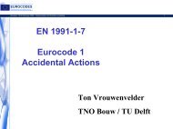
Load distribution by end plates<br />
G. Hanswille<br />
Univ.-Prof. Dr.-Ing.<br />
Institute for Steel and<br />
<strong>Composite</strong> Structures<br />
University of Wuppertal-Germany<br />
~1d<br />
F [kN]<br />
6000<br />
F u<br />
4000<br />
F u = 6047 kN<br />
F u,stat = 4750 kN<br />
δ u = 7.5 mm<br />
t s<br />
t p<br />
σ c<br />
2000<br />
b c<br />
5,0 10,0 15,0<br />
δ [mm]<br />
b = t + 5 t<br />
c<br />
s<br />
p<br />
69
Design rules according to EN 1994-1-1<br />
G. Hanswille<br />
Univ.-Prof. Dr.-Ing.<br />
Institute for Steel and<br />
<strong>Composite</strong> Structures<br />
University of Wuppertal-Germany<br />
σ<br />
c,Rd<br />
= f<br />
cd<br />
⎡<br />
⎢1+ η<br />
⎣<br />
cL<br />
t<br />
d<br />
f<br />
f<br />
yk<br />
ck<br />
⎤<br />
⎥<br />
⎦<br />
A<br />
A<br />
c<br />
1<br />
≤<br />
Ac<br />
f<br />
A<br />
1<br />
cd<br />
≤<br />
f<br />
yd<br />
t s<br />
Load distribution 1:2,5<br />
t p<br />
A 1<br />
f ck<br />
t<br />
d<br />
f yk<br />
A 1<br />
A c<br />
η c,L<br />
concrete cylinder strength A<br />
wall thickness of the tube A1<br />
diameter of the tube<br />
yield strength of structural steel<br />
loaded area<br />
cross section area of the concrete<br />
confinement factor<br />
η c,L<br />
= 4,9 (tube)<br />
η c,L<br />
= 3,5 (square hollow sections)<br />
c ≤<br />
20<br />
σ c,Rd<br />
b c<br />
b = t + 5 t<br />
c<br />
s<br />
p<br />
b c<br />
70
G. Hanswille<br />
Univ.-Prof. Dr.-Ing.<br />
Verification outside the areas of load introduction Institute for Steel and<br />
<strong>Composite</strong> Structures<br />
University of Wuppertal-Germany<br />
F<br />
δ<br />
A<br />
pure bond<br />
(adhesion)<br />
B<br />
mechanical<br />
interlock<br />
σ r<br />
C<br />
friction<br />
Outside the area of load introduction,<br />
longitudinal shear at the interface<br />
between concrete and steel should be<br />
verified where it is caused by<br />
transverse loads and / or end<br />
moments. Shear connectors should<br />
be provided, based on the distribution<br />
of the design value of longitudinal<br />
shear, where this exceeds the design<br />
shear strength τ Rd<br />
.<br />
In absence of a more accurate<br />
method, elastic analysis, considering<br />
long term effects and cracking of<br />
concrete may be used to determine<br />
the longitudinal shear at the interface.<br />
71
Design shear strength τ Rd<br />
G. Hanswille<br />
Univ.-Prof. Dr.-Ing.<br />
Institute for Steel and<br />
<strong>Composite</strong> Structures<br />
University of Wuppertal-Germany<br />
b c<br />
b<br />
τ Rd,o = 0,30 N/mm 2<br />
concrete<br />
encased<br />
sections<br />
y<br />
c y<br />
c y<br />
c z<br />
h<br />
c z<br />
h c<br />
τ<br />
Rd<br />
= τ<br />
Rd,o<br />
β<br />
c<br />
⎡ cz,min<br />
⎤<br />
β c = 1 + 0,02 cz<br />
⎢1<br />
− ≤2,5<br />
c<br />
⎥<br />
⎣ z ⎦<br />
c z - nominal concrete cover [mm]<br />
z<br />
c z,min =40mm (minimum value)<br />
concrete filled tubes<br />
τ Rd<br />
= 0,55 N/mm 2<br />
flanges of partially<br />
encased I-sections<br />
τ Rd<br />
= 0,20 N/mm 2<br />
concrete filled<br />
rectangular hollow<br />
sections<br />
τ Rd<br />
= 0,40 N/mm 2<br />
webs of partially<br />
encased I-sections<br />
τ Rd<br />
= 0,0 N/mm 2<br />
72
G. Hanswille<br />
Univ.-Prof. Dr.-Ing.<br />
Institute for Steel and<br />
<strong>Composite</strong> Structures<br />
University of Wuppertal-Germany<br />
Thank you very<br />
much for your kind<br />
attention<br />
73