Third Quarter - SPE Thermoforming Division
Third Quarter - SPE Thermoforming Division
Third Quarter - SPE Thermoforming Division

You also want an ePaper? Increase the reach of your titles
YUMPU automatically turns print PDFs into web optimized ePapers that Google loves.
®<br />
<strong>Thermoforming</strong><br />
<strong>Quarter</strong>ly<br />
®<br />
A JOURNAL OF THE THERMOFORMING DIVISION OF THE SOCIETY OF PLASTIC ENGINEERS THIRD QUARTER 2010 n VOLUME 29 n NUMBER 3<br />
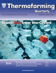
The Sky’s The Limit<br />
INSIDE …<br />
Texture in the Digital Age page 10<br />
New Energy Saving Cost Models page 14<br />
Scholarship Winners pages 24-25<br />
WWW.THERMOFORMINGDIVISION.COM
KYD1079_Post-it_Ad_8x10.5_v8:Layout 1 7/19/10 11:29 AM Page 1<br />
Your medical device part specs point to<br />
KYDEX ® thermoplastic sheet.<br />
KYDEX, LLC knows what’s important to the medical device market, so we make materials<br />
to fit the bill. KYDEX ® thermoplastic sheet delivers everything FR-ABS offers, but that’s only<br />
the beginning. KYDEX ® thermoplastic sheet is also extremely durable and chemical resistant.<br />
In addition, it resists chips, scratches and dents. Plus, we offer an additive to protect against<br />
microbes that cause stains, odors and product deterioration. Add our short run and quick<br />
lead time capabilities, and we’re ready when you are.<br />
For medical device parts that meet all your needs including extreme durability and<br />
antimicrobial additive, tell your thermoformer you want KYDEX ® thermoplastic sheet.<br />
Learn more at www.kydex.com/medical.<br />
The full KYDEX product line is GREENGUARD Certified by the GREENGUARD Children & Schools SM Certification Program. GREENGUARD<br />
certified products contribute to good indoor air quality, helping to limit chemical exposure and improve health. The GREENGUARD INDOOR<br />
AIR QUALITY CERTIFIED Mark is a registered certification mark used under license through the GREENGUARD Environmental Institute.<br />
ISO 9001:2000 | ISO 14001:2004 Certified<br />
6685 Low Street<br />
Bloomsburg, PA 17815 USA<br />
Phone: +1.570.387.6997<br />
Fax: +1.570.387.8722<br />
info@kydex.com<br />
www.kydex.com<br />
© 2010 KYDEX, LLC. All rights reserved. KYDEX is a registered trademark of KYDEX, LLC.
Achieve a sustainable balance<br />
of performance and cost.<br />
Enabled by QINNEX ® technology, UPES ® resin<br />
as an additive to polyolefi ns enables<br />
significant source reduction while increasing<br />
performance at no additional cost.<br />
Environmental Benefits<br />
UPES resin enables improved<br />
processability, material source<br />
reduction and energy savings.<br />
Up to 20% material source<br />
reduction<br />
More efficient machine usage<br />
Recyclable<br />
Improved Performance<br />
When used in thermoforming<br />
applications, UPES resin<br />
enhances the performance of<br />
difficult to mold parts -<br />
providing stronger, thinner and<br />
stiffer packaging solutions.<br />
Improved crush strength –<br />
by up to 140%<br />
33% faster forming rates<br />
Better part definition<br />
Shorter start-ups and reduced<br />
scrap rates<br />
Increased machine time<br />
availability<br />
Reduced Cost<br />
UPES resin helps thermoformers<br />
maintain a cost-competitive<br />
advantage while delivering<br />
material source reduction and<br />
improved performance.<br />
Downgauge<br />
Easy processability up to<br />
20% weight loadings<br />
No additional equipment<br />
needed<br />
Blends well with polyolefins<br />
No output/rate penalties<br />
NOVA Chemicals<br />
UPES@novachem.com | 724.770.6610 | www.upesresin.com<br />
UPES ® and QINNEX ® are registered trademarks of NOVA Chemicals Inc.<br />
is a trademark of NOVA Chemicals Inc.<br />
Visit our Booth 415<br />
September 18-20, 2010 Milwaukee, WI
<strong>Thermoforming</strong><br />
<strong>Quarter</strong>ly ® THIRD QUARTER 2010<br />
VOLUME 29 n NUMBER 3<br />
<strong>Thermoforming</strong><br />
<strong>Quarter</strong>ly ®<br />
Contents<br />
n Departments<br />
Chairman’s Corner x 2<br />
<strong>Thermoforming</strong> in the News x 4<br />
Council Summary x 21<br />
University News x 26<br />
The Sky’s the Limit<br />
Cover Story<br />
A JOURNAL PUBLISHED EACH<br />
CALENDAR QUARTER BY THE<br />
THERMOFORMING DIVISION<br />
OF THE SOCIETY OF<br />
PLASTICS ENGINEERS<br />
Editor<br />
Conor Carlin<br />
(617) 771-3321<br />
cpcarlin@gmail.com<br />
Sponsorships<br />
Laura Pichon<br />
(847) 829-8124<br />
Fax (815) 678-4248<br />
lpichon@extechplastics.com<br />
Page 26<br />
n In This Issue<br />
William McConnell Memorial x 5<br />
2010 Scholarship Winners x 24-25<br />
19th Annual Conference x 28-29<br />
n Features<br />
Industry Practice x 6<br />
Undercuts and Tooling Design for Heavy-Gauge<br />
<strong>Thermoforming</strong><br />
Industry Practice x 10<br />
Texture in the Digital Age<br />
The Art of <strong>Thermoforming</strong> x 12<br />
Eddyline Kayak<br />
The Business of<br />
<strong>Thermoforming</strong> x 14<br />
<strong>Thermoforming</strong> Optimization: Improving Process Efficiency<br />
and Lowering Energy Consumption<br />
Scholarship Winners<br />
www.thermoformingdivision.com<br />
Conference Coordinator<br />
Gwen Mathis<br />
(706) 235-9298<br />
Fax (706) 295-4276<br />
gmathis224@aol.com<br />
<strong>Thermoforming</strong> <strong>Quarter</strong>ly ® is published<br />
four times annually as an informational<br />
and educational bulletin to<br />
the members of the Society of Plastics<br />
Engineers, <strong>Thermoforming</strong> <strong>Division</strong>,<br />
and the thermoforming industry. The<br />
name, “<strong>Thermoforming</strong> <strong>Quarter</strong>ly ® ”<br />
and its logotype, are registered trademarks<br />
of the <strong>Thermoforming</strong> <strong>Division</strong><br />
of the Society of Plastics Engineers, Inc.<br />
No part of this publication may be reproduced<br />
in any form or by any means<br />
without prior written permission of the<br />
publisher, copyright holder. Opinions<br />
of the authors are their own, and the<br />
publishers cannot be held responsible<br />
for opinions or representations of any<br />
unsolicited material. Printed in the<br />
U.S.A.<br />
<strong>Thermoforming</strong> <strong>Quarter</strong>ly ® is registered<br />
in the U.S. Patent and Trademark<br />
Office (Registration no. 2,229,747). x<br />
Cover photo is courtesy of<br />
Tom Derrer, Eddyline Kayak<br />
All Rights Reserved 2010<br />
<strong>Thermoforming</strong> QUArTerLY 1
<strong>Thermoforming</strong><br />
<strong>Quarter</strong>ly ®<br />
Chairman’s Corner<br />
Ken Griep<br />
As we close out the<br />
summer, we forge ahead with renewed<br />
interest in the growth and anticipation<br />
of business success. On behalf of<br />
<strong>SPE</strong>, I would like to welcome you to<br />
our annual conference in Milwaukee,<br />
Wisconsin, September 18th through<br />
September 21st. More than ever,<br />
this conference is provided as an<br />
opportunity to help and inspire you to<br />
continue developing your strategies.<br />
As you canvass the exhibit hall and<br />
participate in the high quality technical<br />
programs, I want to encourage you to<br />
find new ideas and new opportunities.<br />
The participating vendors and experts<br />
are here to both educate and inspire<br />
you and your company with new<br />
innovative concepts such as energy<br />
saving devices and process-enhanced<br />
capabilities.<br />
The conference, sponsored by<br />
your <strong>SPE</strong> <strong>Thermoforming</strong> <strong>Division</strong>,<br />
provides a single location in<br />
which will be showcased the latest<br />
innovations in material science<br />
and process techniques, as well as<br />
machinery developments and tooling<br />
disciplines. We encourage you to bring<br />
your ideas and your questions to the<br />
conference. Within the walls of the<br />
conference center, the <strong>Thermoforming</strong><br />
<strong>Division</strong> has a mass array of<br />
innovation briefs. It is here that your<br />
networking skills will be amplified<br />
as many of the best connections<br />
and conversations are made in the<br />
hallways.<br />
In the days and weeks following<br />
the conference, I encourage you to<br />
grow your business with the same<br />
enthusiasm you experienced during the<br />
conference. In and around your plant,<br />
meet with all of your co-workers.<br />
Provide them with the details and<br />
innovations you have learned while<br />
in Milwaukee. Chances are this<br />
interaction will spark dialog on new<br />
grounds of process improvements.<br />
More importantly, a challenge to your<br />
co-workers will get them involved<br />
with ideas and possible innovations.<br />
Next year, they too may attend the<br />
conference and experience firsthand<br />
the excitement of this great event!<br />
So how is your business doing<br />
Indications show that some areas<br />
of the country are feeling a slight<br />
increase in traffic in new product<br />
development. Other areas are still<br />
struggling. Throughout my discussions<br />
with many thermoformers, all agree<br />
that there is still uncertainty in our<br />
future. However, even with this<br />
uncertainty, some are very blessed<br />
with current levels of production.<br />
Our work is still not done! We<br />
need to educate our audiences that<br />
thermoforming is the process of<br />
choice. We need to increase our<br />
education practices for customers<br />
on new materials that we can offer<br />
and the effects on part performances.<br />
Our websites should explain that our<br />
process is repeatable. If the product<br />
is designed with thermoforming in<br />
mind, it can and will meet the client’s<br />
requirements, but in most cases, it<br />
will exceed their requirements while<br />
decreasing the time to market.<br />
While keeping the doors of your<br />
business opened, there is still another<br />
challenge out there. Each of us<br />
needs to keep current with political<br />
issues on the local, state and of<br />
course the federal levels. Keeping<br />
the doors open and production lines<br />
flowing effortlessly may be the<br />
easy part compared with staying<br />
current on political issues these days.<br />
Our government has new taxation<br />
looming around the corner while<br />
telling businesses how they should<br />
operate. New laws and government<br />
involvement will impact all<br />
manufacturing sectors. I ask you to<br />
stay politically current as you focus on<br />
your core business. Strive to develop<br />
new process techniques and business<br />
relationships. This will not only<br />
improve your bottom line but also may<br />
help save a little green outside! Be<br />
aware of what our elected officials are<br />
saying and doing.<br />
Moving past politics, there is some<br />
positive news to report. This past year<br />
your <strong>SPE</strong> <strong>Thermoforming</strong> <strong>Division</strong><br />
was selected to received the Gold<br />
Pinnacle Award as recognition for<br />
creating outstanding member value<br />
within <strong>SPE</strong>. It is a true testament of<br />
the hard work that this organization<br />
has compiled these past years. Way<br />
to go! We also thank all our members<br />
for their help and support making this<br />
award possible.<br />
With this quarterly issue also<br />
comes sad news. As Chairman, it is<br />
my duty to inform you of the passing<br />
of two fellow members from our<br />
thermoforming industry: William K.<br />
McConnell on June 5th and David<br />
M. Bestwick on July 18th. Both were<br />
a true inspiration to our industry<br />
and will be greatly missed. The<br />
<strong>SPE</strong> <strong>Thermoforming</strong> <strong>Division</strong> and<br />
associated industries would like to<br />
extend our thoughts and prayers to<br />
their families.<br />
Thank you for your continued<br />
support and get the word out: Do<br />
<strong>Thermoforming</strong>!<br />
If you have any view points or<br />
comments please feel free to contact<br />
me. I would like to hear from you. x<br />
Ken@pcmwi.com<br />
2 <strong>Thermoforming</strong> QUArTerLY
<strong>Thermoforming</strong><br />
<strong>Quarter</strong>ly ®<br />
New Members<br />
Mike O’Hara<br />
C&K Plastics<br />
Metuchen, NJ<br />
Gary D. Watts<br />
The Tegrant Corporation<br />
De Kalb, IL<br />
Elmer Escobar<br />
C&K Plastics<br />
Metuchen, NJ<br />
Scott A. Brown<br />
Replex Plastics<br />
Mount Vernon, OH<br />
Nicole F. Whiteman<br />
NatureWorks LLC<br />
Minnetonka, MN<br />
Paul Sturgeon<br />
KLA Industries, Inc.<br />
Cincinnati, OH<br />
Kara A. Shell<br />
Replex Plastics<br />
Mount Vernon, OH<br />
Mike Hanson<br />
Fabri-Kal<br />
Kalamazoo, MI<br />
Matt Piercy<br />
Printpack Inc.<br />
Williamsburg, VA<br />
David Fry<br />
Brentwood Industries<br />
Inc.<br />
Reading, PA<br />
Patrick Monahan<br />
Thule<br />
Southbury, CT<br />
James Radford<br />
Howard City, MI<br />
Michael Suchocki<br />
Tekra Corp.<br />
New Berlin, WI<br />
Tyler Martin<br />
Octal Inc.<br />
Plano, TX<br />
J. Negrey<br />
Poly Form Int'l. Inc.<br />
Knox, IN<br />
Matthew P. Werden<br />
Saint Clair, MI<br />
David J. Lawrence<br />
Master Pac Corp.<br />
St. Louis, MO<br />
Dan Kellenberger<br />
EGR USA<br />
Ontario, CA<br />
Ronald Staub<br />
Say Plastics Inc.<br />
McSherrystown, PA<br />
Dale Akin<br />
Jamestown Plastics Inc.<br />
Brocton, NY<br />
Joe Campbell<br />
Packaging Plus LLC<br />
La Mirada, CA<br />
Darrel J. Blocksom<br />
Tek Packaging<br />
Huntley, IL<br />
James Hutter<br />
Federal Way, WA<br />
James Tedesco<br />
SencorpWhite<br />
Hyannis, MA<br />
Kathy Ying Xuan<br />
PARC Corporation<br />
Romeoville, IL<br />
Michael Vallafskey<br />
T. O. Plastics, Inc.<br />
Clearwater, MN<br />
Ned R. Pendleton<br />
Pactiv Corporation<br />
Lake Forest, IL<br />
Ataulla Khan<br />
Interplast Co. Ltd.<br />
Sharjah, UAE<br />
Gustavo Gomes De Amorim<br />
Curitiba Parana CEP, Brazil<br />
Rangasamy Pitchai<br />
Mason, OH<br />
Harold A. Keller<br />
K&K <strong>Thermoforming</strong>, Inc.<br />
Southbridge, MA<br />
Tadhg Whooley<br />
Ceramicx Ireland Ltd.<br />
Ballydehob Co. Cork, Ireland<br />
Bonnie Hinze<br />
Oscar Mayer<br />
Madison, WI<br />
Raymond S. Harp<br />
Rowmark<br />
Findlay, OH<br />
Patrick Johnsen<br />
PTi<br />
Aurora, IL<br />
Thomas Huber<br />
Kiefel GmbH<br />
Freilassing, Germany<br />
Phil LaViolette<br />
Minimizer<br />
Blooming Prairie, MN<br />
Lee J. Major<br />
Visionpak Pty. Ltd.<br />
Bayswater, VIC Australia<br />
Joy Sarmiento Falaminiano<br />
Higher Institute for Plastics<br />
Fabrication<br />
Riyadh, Saudi Arabia<br />
Rich J. Lucia<br />
C W Thomas<br />
Philadelphia, PA<br />
Ross Norman Hall<br />
Award Plastics & Displays<br />
Christchurch, New Zealand<br />
Dirk Smith<br />
Boca Raton, FL<br />
David R. McIntosh<br />
Fabri-Kal Corporation<br />
Kalamazoo, MI<br />
Angelo Vissas<br />
Processing Technologies International<br />
Joel D. Schmidt<br />
Perfecseal<br />
Oshkosh, WI<br />
Jim Cowan<br />
Alto Packaging Ltd.<br />
Hastings, New Zealand<br />
Andrew Mitchell<br />
Solo Cup Company<br />
Lake Forest, IL<br />
Amelia Cheever<br />
J.P. Plastics, Inc.<br />
Bridgewater, MA<br />
Benjamin Mueth<br />
Southern Illinois University<br />
Edwardsville<br />
Belleville, IL<br />
Roger D. Hanna, Jr.<br />
Highland Corporation<br />
Mulberry, FL<br />
Trevor J. Foster<br />
Packaging Needs Pty. Ltd.<br />
Dandenong South, Australia<br />
John Thackray<br />
Kydex LLC<br />
Bloomsburg, PA<br />
Dave Carstensen<br />
Xact Wire Edm. Corp.<br />
Waukesha, WI<br />
Huy P. Thach<br />
Rexam Food Containers<br />
Union, MO<br />
Michael Sherrill<br />
Fabri-Kal Corp.<br />
Hazle Twp., PA<br />
Ronald P. Kelly<br />
CM Packaging<br />
Lake Zurich, IL<br />
John Ammons<br />
Inline Plastics Corp.<br />
McDonough, GA<br />
Brian Wingard<br />
GDC<br />
Goshen, IN<br />
Joel M. Cormier<br />
Oakwood Energy Management<br />
Dearborn, MI<br />
Michael R. Merwin<br />
FLEXcon<br />
Spencer, MA<br />
Yannick Demers<br />
St.-Jean-sur-Richelieu, QC, Canada<br />
<strong>Thermoforming</strong> QUArTerLY 3
<strong>Thermoforming</strong> in the news<br />
Plastics Packaging:<br />
Sonoco requires<br />
APT, leading CPET<br />
tray thermoformer<br />
By Matt Defosse, PlasticsToday.com<br />
Published: June 30th, 2010<br />
Associated Packaging Technologies<br />
Inc., which claims to be the world’s<br />
leading processor of crystallized<br />
polyethylene terephthalate (CPET)<br />
trays, has been scooped up by<br />
Sonoco, one of the world’s largest<br />
packaging processors. Sonoco paid<br />
about $120 million all-cash for<br />
APT, a price that includes the cost<br />
of paying off various obligations of<br />
APT.<br />
Why APT In a statement,<br />
Harris DeLoach Jr., president<br />
and CEO at Sonoco, explained,<br />
“With this acquisition, Sonoco<br />
has significantly expanded its<br />
existing thermoforming plastic<br />
container capabilities into the<br />
growing global frozen, chilled and<br />
ready-to-eat food markets. While<br />
APT is today the leading global<br />
supplier of CPET containers,<br />
we believe its proprietary<br />
material formulations and rotary<br />
thermoforming technology provide<br />
a strong platform for significant<br />
product development and growth.<br />
In addition, this acquisition will<br />
help accelerate Sonoco’s current<br />
development of multilayer barrier<br />
polypropylene food containers.”<br />
Sonoco expects the acquisition<br />
to be modestly accretive this<br />
year and is expected to generate<br />
annualized sales of approximately<br />
$150 million. APT was previously<br />
majority owned by investment funds<br />
controlled by Castle Harlan Inc.<br />
APT runs thermoforming<br />
facilities in Ontario, Canada; at<br />
two sites (Chillicothe, MO and<br />
Waynesville, NC) in the U.S.;<br />
and at Carrickmacross, Ireland,<br />
and employs more than 400<br />
workers. CPET trays are dualovenable<br />
(conventional and<br />
microwave) and see use primarily<br />
in packaging of ready-to-eat frozen<br />
meals. APT’s capacity is enough<br />
to process some 3 billion CPET<br />
containers annually; it standardizes<br />
on extrusion machinery from Davis-<br />
Standard and thermoformers<br />
from Lyle.<br />
Last year, APT announced it<br />
was adding polypropylene and<br />
multi-layer film extrusion and<br />
thermoforming capacity to its<br />
Cambridge, ON facility, raising<br />
capacity there by about 8 million<br />
lbs./year. It also was the first<br />
processor in the U.S. to thermoform<br />
frozen meal trays incorporating postconsumer<br />
recycled plastic. x<br />
<strong>Thermoforming</strong> <strong>Division</strong><br />
Receives<br />
Gold Pinnacle Award<br />
The Pinnacle Award recognizes achievements by <strong>SPE</strong> Sections and<br />
<strong>Division</strong>s that successfully create and deliver member value in four<br />
categories: Organization, Technical Programming, Membership, and<br />
Communication. Two levels of the award are available – Silver and Gold –<br />
and the <strong>Thermoforming</strong> <strong>Division</strong> received a Gold Pinnacle Award this year.<br />
Pictured are Roger Kipp, Councilor (left) receiving the award from Paul<br />
Anderson, 2009-2010 <strong>SPE</strong> President, at the Leadership Awards Luncheon<br />
at ANTEC in Orlando, Florida this past May.<br />
4 <strong>Thermoforming</strong> QUArTerLY
In Memoriam<br />
William Keller McConnell, Jr.<br />
The <strong>Thermoforming</strong> Industry has<br />
suffered a great loss with the passing<br />
of William “Bill” K. McConnell, Jr. If<br />
one individual could be identified as a<br />
major contributor to the technical growth<br />
of our industry, it would surely be Bill.<br />
Founder and President of the McConnell<br />
Company, Inc., Bill died on June 5, 2010<br />
after a very short illness. Over the years,<br />
as a consultant to the plastics industry,<br />
Bill became a colleague, a mentor, an<br />
instructor and a good friend to countless<br />
people in our industry and those<br />
associated with it.<br />
Active in the thermoforming<br />
industry since 1948, Bill McConnell<br />
was a dedicated alumnus of Texas<br />
A&M University where he majored in<br />
Aeronautical Engineering. He spent the<br />
WWII years teaching aerial navigation<br />
for the Navy. In the post-war years, he<br />
started and operated a non-scheduled<br />
airline for two years. His personal life, as<br />
well as his business life, represented a<br />
full palate of activities. He and his wife<br />
Pat raised three sons: Sandy, Steve<br />
and Scott. With the support and care of<br />
his family, Bill found time for camping,<br />
traveling and consulting. Until her death<br />
in 2001, Pat was a major support in all<br />
phases of his professional career.<br />
In India, the most revered individuals in<br />
society are the teachers who share their<br />
knowledge to improve the lives of others.<br />
This status can most certainly be applied<br />
to Bill. It would be impossible to count<br />
the number of people in our profession<br />
that were taught and influenced by<br />
Bill McConnell. He was a person who<br />
gained and held the respect of countless<br />
individuals due to his dedication and<br />
caring attitude. Much of his consulting<br />
work was done in manufacturing analysis,<br />
assistance in product development,<br />
process troubleshooting, in-house<br />
training seminars and development<br />
of processing specifications. He was<br />
regularly asked to be an expert witness<br />
and consultant to the legal fields on<br />
plastics-related projects. Bill’s pioneering<br />
contributions to the plastic industry<br />
are well recognized. He was one of<br />
the innovators in thermoforming and<br />
plastic processing for the industrial and<br />
aerospace industries.<br />
In his early years in plastics, Bill<br />
McConnell gained 14 years of invaluable<br />
experience in thermoforming, injection<br />
molding and blow molding as vicepresident<br />
and General Manager of<br />
Texstar Plastics, a custom processor<br />
and thermoplastic sheet laminator.<br />
Using his knowledge, he organized a<br />
manufacturer’s representative business<br />
dealing in plastic sheet, film and<br />
equipment. After 20 years, he sold this<br />
business to a long-time employee and<br />
founded AAA Plastic Equipment, Inc.,<br />
a manufacturer of shuttle and rotary<br />
thermoforming equipment, where he<br />
served as CEO and General Manager.<br />
In 1966, AAA Plastic Equipment joined<br />
the SPI. Bill was active on the Machinery<br />
<strong>Division</strong> Safety Committee until 1976.<br />
In 1960, Bill founded McConnell<br />
Company, Inc., and served as President<br />
and Owner until his death. What started<br />
as a sales representative business<br />
became internationally recognized as one<br />
of the premier thermoforming consultant<br />
companies in the world. Excelling in<br />
offering technical advice and services,<br />
Bill enjoyed bringing all of his experience<br />
together to help companies succeed. His<br />
associate partners will endeavor to carry<br />
on his work and legacy.<br />
Since his early career, Bill McConnell<br />
has earned many awards. He received<br />
the first annual “Thermoformer of the<br />
Year” award from the <strong>Thermoforming</strong><br />
<strong>Division</strong> of the Society of Plastics<br />
Engineers. He was also one of the 136<br />
Fellows of the Society, out of 36,000<br />
members. In 1997, he was honored<br />
Lifetime Achievement Award<br />
with a “Lifetime Achievement Award”<br />
at the <strong>Thermoforming</strong> Conference and<br />
also inducted into the Plastics Pioneers<br />
Association that same year. He was<br />
the first Thermoformer for this group.<br />
Bill has been a member of <strong>SPE</strong> since<br />
1953 and has served as an International<br />
Membership Chairman, Education<br />
Chairman and President of the North<br />
Texas Section. He was one of the<br />
founding members of this <strong>Division</strong> and<br />
was a former chairman. Since 1972,<br />
he conducted two-, three- and fourday<br />
thermoforming seminars for the<br />
<strong>SPE</strong>. Bill has also taught international<br />
seminars in England (Rubber & Plastic<br />
Institute), Belgium, Denmark, Australia,<br />
South Africa, Canada, and Mexico. He<br />
served on the Board of Directors of the<br />
<strong>Thermoforming</strong> <strong>Division</strong> until his passing<br />
this year.<br />
As well as seminars and lectures, Bill<br />
wrote many articles on all phases of<br />
thermoforming, including contributions<br />
to textbooks and publications including<br />
the Modern Plastics Encyclopedia. He<br />
wrote the thermoforming chapter for<br />
the “Handbook of Plastic Materials and<br />
Technology” by Irvin Rubin. His textbook,<br />
“<strong>Thermoforming</strong> Technology,” is used<br />
as the manual in his seminars. Bill also<br />
created a special training course for<br />
designers and engineers on what can and<br />
cannot be done in thermoforming.<br />
Anyone who has had the privilege of<br />
meeting and learning from Bill McConnell<br />
understands that his joy of people and<br />
his dedication to helping them achieve<br />
success was his goal in business and in<br />
his personal life. He will be remembered<br />
for many different attributes which include<br />
his colorful airplane ties and for his<br />
special motto “If you can’t measure it, you<br />
can’t control it.”<br />
Our thoughts and prayers are with Bill’s<br />
family. His memory will continue to serve<br />
as an inspiration for the many people that<br />
knew him, and for those who will benefit<br />
from his pioneering spirit. x<br />
<strong>Thermoforming</strong> QUArTerLY 5
<strong>Thermoforming</strong><br />
<strong>Quarter</strong>ly ®<br />
Industry Practice<br />
Undercuts & Tooling Design for<br />
Heavy-Gauge <strong>Thermoforming</strong><br />
Art Buckel, Associate Consultant, McConnell Co., Inc.<br />
When I first found vacuum forming in the late 1960s as a<br />
way to manufacture plastic parts for my customer’s needs,<br />
I was advised by the “old pro” that vacuum form molds were all<br />
truncated pyramids or cones [see Illustration 1]. In other words,<br />
Illustration #1.<br />
parts with no pointy tops and very heavy draft on all sides. When I<br />
suggested that it would be extremely difficult to sell these shapes<br />
to all customers without considerable modifications, he agreed<br />
and said “of course you can lengthen the parts, and widen them,<br />
and use various different heights, and add rounded corners – but<br />
always retain the original thought.”<br />
My great pleasure of the last 40 years has been to design molds<br />
for every conceivable market and application: parts with sides<br />
with no draft or reverse draft; undercuts in one or more locations;<br />
some that have undercuts around the entire base. However, I<br />
have always retained that original thought: “Design the mold to<br />
give the customer exactly what he needs while ensuring that the<br />
formed part releases as easily as possible.” Put another way –<br />
design for ease of manufacture.<br />
In this article, we are going to look at a number of vacuum formed<br />
and pressure formed parts with undercuts ranging from quite<br />
simple to very complex and how the mold was designed to meet<br />
the customer’s need.<br />
Keeping it Simple<br />
One of the simpler things to achieve in a vacuum formed part is<br />
a handle on the front panel of a cabinet or a drawer front. You<br />
should design the part with a scooped-out section as long as<br />
you wish the handle to be, usually about 5-6" in length, with the<br />
hand-grab in the center [see Illustration 2]. With the profile of<br />
the hand-grab flowing into the ends of the scooped area (where<br />
Illustration #2.<br />
the undercut section is a separate piece) the hot plastic material will<br />
flow down into the recess, over the shape, and back up the other<br />
side of the scoop. Since the loose section is hinged at the top edge<br />
with a coil spring under the other edge, the loose section will rise at<br />
the undercut edge when the cooled part begins to release from the<br />
mold. It will then lift up until the formed part clears the overlaying<br />
section. At this time the part is free of the mold and the handle<br />
section snaps back into place ready for the next hot sheet to form.<br />
With the proper design and fabrication of the mold, this action will<br />
repeat thousands of times with little or no problems. It is perfect for<br />
use on high volume production on a rotary machine.<br />
Another good way to create an undercut handle is with a loose part<br />
to create the hand-grab. This technique is typically for use on smaller<br />
part quantities run on a single-station machine. For example, a<br />
section of heavy-walled PVC or ABS pipe about one half inch in<br />
diameter is used. Design the mold with the same scooped-out area<br />
and a wall running the length of the cavity one half inch lower than<br />
the face of the panel. At both ends of the cavity, build stops that<br />
create areas that contain small steps on the sides for the pipe to butt<br />
up against and to retain the pipe when it is inserted [see Illustration<br />
3]. When the hot sheet forms over the pipe section it will create the<br />
undercut hand-grabs and carry the loose part away.<br />
Illustration 4 shows a mold for forming a display rack of greeting<br />
cards with an undercut riser in the front to prevent the cards from<br />
slipping out of their proper display space. The moving section of<br />
the mold is a flat piece of aluminum stock with two pivot hinges<br />
at the rear corners, and a return spring under the part. As the hand<br />
in the photo shows, when the formed sheet is cooled and begins to<br />
6 <strong>Thermoforming</strong> QUArTerLY
Illustration #3.<br />
Illustration #6.<br />
has formed and cooled it begins to dismount the mold, lifting the<br />
undercut end of the mold until it clears the undercut allowing the<br />
mold to drop back to its forming position ready for the next hot<br />
sheet.<br />
Products that have been in great demand for a number of years<br />
are “work in process containers” that will stack using projecting<br />
sections on the outside of the containers [see Illustration 7].<br />
Illustration #4.<br />
release from the mold, the undercut section lifts the flap until it is<br />
clear. The mold section then snaps back into place, ready for the<br />
next hot sheet. This mold is about 45" x 27" with many hinged<br />
sections.<br />
Some undercuts shown in preliminary drawings of the required<br />
plastic part appear to be a real problem as the part design does<br />
not lend itself to a moving section in the mold [see Illustration 5].<br />
On the right edge of the part is a severe undercut. For the mold<br />
Illustration #7.<br />
A two-up mold to form this type of product is shown with the<br />
moving sections along both sides and around the corners onto<br />
the ends, which are made up of four sections. At the bottom of<br />
the molds are steps that form a “step surface” inside the plastic<br />
part where the projecting section can rest and be contained on the<br />
sides for good stacking. The design of the four moving sections<br />
is achieved by using pivot pins at the extreme ends of the short<br />
sections. When the ends of the long side sections are pulled into<br />
the mold, they cause the loose sections to move entirely within<br />
the mold [see Illustration 8 on page 10] allowing the formed<br />
and cooled material to dismount the mold. The movement of the<br />
sections can be induced by pneumatic or hydraulic cylinders or<br />
electric motors, pushing and pulling the sections.<br />
Illustration #5.<br />
design solution [see Illustration 6], where the mold platen surface<br />
is separate from the platen box, there are two pins in the walls of<br />
the box which create two pivot points. Note that the pivot points<br />
are not in the center of the mold. The platen surface rests on a ledge<br />
inside the platen box, on the undercut side only. When the hot sheet<br />
TPO Front Facia Example<br />
The next part we will examine is a TPO front facia required by<br />
the French auto manufacturer Renault for limited production in<br />
South America. Because the part swept around the complete front<br />
of the auto, and then turned in at the front wheel openings on both<br />
sides, it created a severe undercut at each end of the mold. There<br />
were two important customer requirements that were critical to<br />
this project:<br />
(continued on next page)<br />
<strong>Thermoforming</strong> QUArTerLY 7
Illustration #8.<br />
1. Absolutely no mark on the outside indicating any separate<br />
mold sections.<br />
2. Uniform material thickness over the entire plastic part.<br />
The design answer was to build loose undercut parts that would<br />
slide up inclined ramps on the main body of the mold [see<br />
Illustration 9]. However, the most important requirement of the<br />
Illustration #9.<br />
mold design was to guarantee the “no mold mark” on the finished<br />
parts over large production runs. An additional challenge was<br />
how to get the two heavy moving sections easily up the slide until<br />
the plastic part was freed, and then how to “gently” get the mold<br />
sections back down the ramp without slamming the bottom rests.<br />
Achieving the “No Mark” Requirement<br />
The two end sections were cast of aluminum as was the main<br />
body of the mold. They had cooling lines cast in them, connected<br />
to the lines in the main body of the mold with flexible woven steel<br />
tubes [see Illustration 10]. It was important that the aluminum<br />
behind the bronze plates, on which the two moving sections slid,<br />
were temperature-controlled with cooling lines. (Author’s Note:<br />
NEVER build a mold with sliding sections moving on similar<br />
metals. They will cause galling of the aluminum surfaces and<br />
metal pieces will come off of the contact area, which will soon<br />
lead to binding.)<br />
Notice in Illustration 10 how the two guides are built in to control<br />
the positioning of the sliding part. Also, the pivoting lock in the<br />
center of the bronze plate that secures the end section when it is<br />
down in the forming position is turned by an electric motor: one<br />
direction to lock, and reverse to unlock when the part is formed<br />
and cooled. It is critical to remember not to use the hollow of the<br />
Illustration #10.<br />
mold as a vacuum chamber! When the vacuum comes on, and the<br />
ambient air pushes the hot sheet onto the mold, it will tend to move<br />
any loose part no matter how tightly it is locked in place, because<br />
there is no equal pressure pushing back.<br />
When designing a mold with loose sections that must not leave<br />
a mark, you will be amazed at how well it will work if you run a<br />
vacuum manifold through the mold and run flexible tubes from the<br />
manifold to the inside surface of the mold at all of the vacuum holes.<br />
During forming, the inside of the mold has the same ambulant air<br />
pressure as the room in which it is being formed and the inside of<br />
the mold is pushing back against the pressure caused by the vacuum<br />
forming of the sheet. Thus the loose section will not move during<br />
the vacuum forming period.<br />
To handle the weight of the two moving end sections, each one has a<br />
steel cable fastened to it that runs through a hole in the bronze plate,<br />
over a pulley, and is secured to a counterweight within the body of<br />
the mold. The counterweight hangs in a tube, and as the part begins<br />
to dismount the mold, the ends moved up the slides quite easily<br />
due to the falling weight inside the mold. When the formed plastic<br />
part undercuts have cleared the moving mold sections, they slide<br />
down the ramps slowly due to the resistance of the weights. Each<br />
counterweight reduces the sliding section of the mold from a true<br />
34 pounds to a lifting and falling weight of only 4 pounds.<br />
What is probably the most common undercut in today’s<br />
thermoforming industry is the pressure formed housing with a<br />
return at the base (either partial or completely around the base.)<br />
Since the pressure formed housing is formed into a cavity mold, the<br />
return is formed with an over-hanging aluminum section at the top<br />
of the mold [see Illustration 11 – the brown section at the bottom of<br />
the mold is a piece of a formed part that protects the molds textured<br />
surface when it is not in use].<br />
I have selected this particular example because of the complexity<br />
of the total design, Notice the severity of the undercuts in the four<br />
corners, each more than 1" deep [see Illustration 12]. In order to<br />
form these corners with adequate material thickness, I designed<br />
four articulating pushers in the corners of the plug. These pushers<br />
were pieces of aluminum stock with wooden shapes on the forming<br />
ends. The aluminum was shaped to fit into the plug where it had a<br />
pivot point, and the other end extended out of the side of the plug<br />
where it rested on the top surface of the hot sheet as the plug pushed<br />
the material down into the cavity of the mold [see Illustration 13<br />
8 <strong>Thermoforming</strong> QUArTerLY
Illustration #11.<br />
Illustration #12.<br />
There are a number of ways to design this overhang in the cavity<br />
mold that produces the undercut. The first and simplest way is<br />
to use one or more loose tooling sections that fit into a special<br />
opening at the mold’s upper edge and come out in the formed<br />
plastic part, as shown in the previous example. The loose parts<br />
are then removed from the formed part, and placed back on<br />
the mold while the next sheet is heating. With 2 or more loose<br />
sections on adjoining sides, the corners will usually meet at 45%<br />
angles.<br />
Other ways to move the over-hanging mold sections away from<br />
the main mold cavity during part removal include:<br />
1. Hinge the loose sections at the rear lower edge, so that the<br />
sections swivel up and back as the part dismounts the mold<br />
until it clears the undercut area of the plastic parts which<br />
then drop back into the forming position.<br />
2. Move the loose sections horizontally back into the mold<br />
body to clear the formed plastic part during its removal<br />
from the mold. Then move the loose sections back into the<br />
forming position.<br />
3. The movement of the mold sections can be caused by the<br />
use of pneumatic or hydraulic cylinders, or electric motors.<br />
A ring gear and pinion is often used to move large, heavy<br />
sections.<br />
This article is offered to not only assure the readers that you can<br />
create molds with undercuts, but also to emphasize that it is most<br />
important to create good designs of the critical mold sections.<br />
It is always a good idea to cut out a cardboard of the moving<br />
section, to scale, and pin it over the drawing to proof the design<br />
and determine that there is no interference. x<br />
<strong>SPE</strong> Veteran Recognized<br />
by Western Plastics Pioneers<br />
Illustration #13.<br />
showing fingers pushing the extended ends of two of the pushers,<br />
which cause the wooden sections to move out into the undercut<br />
section of the mold]. As the plug moves down into the bottom of<br />
the mold, the hot forming sheet laying over the top of the overcut<br />
sections of the mold, pushes the aluminum ends up and into the<br />
plug, pivoting the pushers out and pushing the hot sheet back into<br />
the deep corners. This design produced large quantities of pressure<br />
formed parts.<br />
Art Buckel was recently recognized by the Western<br />
Plastics Pioneers Association and was conferred with their<br />
Hall of Fame Award for his outstanding achievements to<br />
the plastics industry.<br />
The objectives of the Plastics Pioneers Association shall be<br />
to recognize achievement in the field of plastics/polymer<br />
science, engineering, technology and management; to<br />
support industry-wide educational programs; and to<br />
promote the study and improvement of plastics, science<br />
engineering and technology.<br />
<strong>Thermoforming</strong> QUArTerLY 9
<strong>Thermoforming</strong><br />
<strong>Quarter</strong>ly ®<br />
10 <strong>Thermoforming</strong> QUArTerLY<br />
Industry Practice<br />
Texture in the Digital Age<br />
Chris Spellman, Sales Engineer, Mold-Tech, Carol Stream, IL<br />
The process of texturing molds has always been<br />
recognized as an artistic and as a craft-based<br />
process. A look inside the texturing process will<br />
reveal the technician applying his tools using the<br />
smallest of fine-tip paintbrushes and X-acto knives,<br />
all being done under the highest magnification<br />
possible. As mold-making has moved squarely into<br />
the CAD/CAM world, texturing, like mold polishing,<br />
has remained an art form. While this remains true<br />
today, there are new technical developments that are<br />
having a significant impact on quality and cost.<br />
Texturing is achieved through a controlled<br />
corrosion process. Areas of the mold that are not<br />
to be textured are protected with tapes, paints, and<br />
waxes. These are also called “resists” as they prevent<br />
the etchant from etching the mold. Once the areas of<br />
the mold to be textured are defined by the masking<br />
process, the next step is to apply the pattern resist to<br />
the mold surface. In most cases this pattern is a wax<br />
resist and it has the appearance of a leather grain or<br />
a wood grain. These patterns have traditionally been<br />
achieved by producing a master plate that allows the<br />
wax pattern to transfer from the plate onto a tissue<br />
paper or transfer sheet. The transfer sheet is then<br />
“wallpapered” on to the mold surface.<br />
The master plate process has some limitations, the<br />
first of which is size. Current uses are limited to 24" x<br />
36" which requires that multiple sheets of wallpaper<br />
be patched on larger areas. The seams between these<br />
sheets require skillful and detailed hand work to make<br />
a seamless transition. This is very time consuming<br />
and results are based on the technician’s skill, the<br />
time allotted to the task and the ability of the touchup<br />
resist to last through the etching process.<br />
This is an area where MoldTech has advanced<br />
into the digital age. New digital transfer technology<br />
can produce pattern sheets that are 48" x 72", giving<br />
the mold surface a seamless pattern. This eliminates<br />
time and the possible breakdown of the hand-painted<br />
seams. The result is greater efficiency, lower costs, less<br />
risk, and a more consistent pattern application.<br />
Digital Transfer Technology also allows for rapid<br />
pattern development capabilities. Whether creating<br />
new patterns or manipulating existing patterns, Digital<br />
Transfer Technology has greatly reduced the task time,<br />
while the design options have exploded. Brand new<br />
options include new “morphing” textures, where one<br />
texture pattern can blend into another with seamless<br />
transition. Geometric patterns, like a diamond grid,<br />
can now morph into a leather pattern. Traditionally,<br />
there have been break lines between grains of different<br />
styles. These are no longer required. Additional<br />
advances include the ability to take the file of a specific<br />
mold surface and design a grain to conform to the<br />
contours of that surface. This can result in a texture<br />
that changes or morphs from one pattern to another<br />
along the contour or profile change on a mold surface.<br />
Geometric textures (those that have patterns laid out<br />
in rows) can also be developed to “wrap” the complex<br />
curves of a tool surface. This is another advance<br />
that saves time, lowers costs and reduces risk while<br />
reducing manual touch-ups as well as eliminating<br />
distortion that can occur with geometric patterns<br />
on complex curves. Given the new popularity of<br />
geometric textures, this new technology is producing<br />
results never before seen.<br />
Another design advantage of the digital process<br />
is the ability to incorporate corporate logos into the<br />
texture. By taking the artwork of a company logo and<br />
developing a texture pattern that includes it, textures<br />
can now be created that are both decorative and that<br />
reinforce brand identification.<br />
The chemistry used to etch these patterns into<br />
machined and cast aluminum molds is another area<br />
of development. The texturing industry has for years<br />
strived to produce the sharp, well-defined grain<br />
profiles that were available with steel tooling. Recent<br />
breakthroughs have produced an aluminum etchant<br />
that does now provide texture profiles similar to those<br />
achieved in steel.
Why<br />
Join<br />
Figure 1: Example of textured logo to enhance brand.<br />
Textured surfaces often include the design intent of gloss management.<br />
This is best achieved with sharper texture profiles. Lower gloss matte<br />
finishes and stipples, more realistic looking woodgrains, and leather grains<br />
that display natural creases, wrinkles, and pore patterns all benefit from a<br />
sharper etch profile. This new chemistry also has the advantage of better<br />
texture depth control and enhanced repair results. High appearance parts<br />
that previously required injection molding from steel tooling may now be<br />
considered for thermoformed parts. x<br />
PRO<strong>SPE</strong>CTIVE<br />
AUTHORS<br />
<strong>Thermoforming</strong> <strong>Quarter</strong>ly ® is an<br />
“equal opportunity” publisher!<br />
You will notice that we have several departments and<br />
feature articles. If you have a technical article or other<br />
articles you would like to submit, please send to<br />
Conor Carlin, Editor. Please send in .doc format.<br />
all graphs and photos should be of sufficient size and<br />
contrast to provide a sharp printed image.<br />
It has never been more<br />
important to be a member<br />
of your professional<br />
society than now, in<br />
the current climate of<br />
change and volatility<br />
in the plastics industry.<br />
Now, more than ever,<br />
the information you<br />
access and the personal<br />
networks you create can<br />
and will directly impact<br />
your future and your<br />
career.<br />
Active membership in<br />
<strong>SPE</strong> – keeps you current,<br />
keeps you informed, and<br />
keeps you connected.<br />
The question really isn’t<br />
“why join” but …<br />
Why<br />
Not<br />
<strong>Thermoforming</strong> QUArTerLY 11
<strong>Thermoforming</strong><br />
<strong>Quarter</strong>ly ®<br />
Tom Derrer, Eddyline Kayak<br />
The Art of <strong>Thermoforming</strong><br />
Eddyline Kayak<br />
[Editor’s Note: We wish to thank Tom Derrer of Eddyline Kayak for contributing<br />
this highly original piece to <strong>Thermoforming</strong> QuarTerly. It is just another example<br />
of how thermoforming as a process is being used in new, innovative ways.]<br />
The City of Bend, Oregon and several other local area businesses sponsor an “Art in the Park” program.<br />
Each year they solicit entries from numerous artists for project ideas. They have a selection board made up<br />
of commissioners and citizens and they make a selection which is funded by the city and sponsors. This year,<br />
Troy Pillow (www.pillowstudios.com), a Seattle artist, submitted a proposal and rendering of the kayak “flower”<br />
sculpture. It was voted in unanimously by the group. Troy then researched various kayak manufacturers and methods<br />
of construction and approached Eddyline. After several meetings discussing the merits of various materials and<br />
looking at different kayaks, Troy decided to use our Merlin LT model. Eddyline put nine boats and nine paddles<br />
into production to meet his needs, three of each color: red, orange and yellow. The paddles (the stamen of the<br />
flowers) are all black. Troy had engineering help to design the structure, which he says has been tested to winds of<br />
85 mph. It was erected on May 5th and 6th, 2010.<br />
Close-up of the ”stem” of the kayak<br />
structure.<br />
Tom Derrer and his wife, Lisa, photographed<br />
beside the sculpture in Bend, OR.<br />
12 <strong>Thermoforming</strong> QUArTerLY
<strong>Thermoforming</strong> QUARTERLY 13
<strong>Thermoforming</strong><br />
<strong>Quarter</strong>ly ®<br />
The Business of <strong>Thermoforming</strong><br />
<strong>Thermoforming</strong> Optimization: Improving Process<br />
Efficiency and Lowering Energy Consumption<br />
William Karszes, PhD, OCTAL, Roswell, GA<br />
Mohammed Razeem, OCTAL, Dallas, TX<br />
Jerome Romkey, GN, Chester, Novia Scotia<br />
[Editor’s Note: We are grateful to the authors for providing such a comprehensive<br />
article that includes cost and energy savings models. We believe it is important<br />
to point out that the models and subsequent data are presented in <strong>Thermoforming</strong><br />
QuarTerly as illustrative examples of how processors might examine their own<br />
operational performance. Equipment type and processing parameters will vary across<br />
the industry.]<br />
SUMMARY<br />
This paper was written to explore<br />
the effects of material and machine<br />
choice on the thermoforming process.<br />
The data and findings related to<br />
production costs, energy consumption<br />
and process optimization. Within this<br />
paper we explore two different types<br />
of machines. One is distinguished<br />
by the heating of the plastic by<br />
conduction of heat into the plastic<br />
from a heated platen. This process<br />
is defined as contact heat method<br />
(GN-DX series). The second process<br />
is where the heat is introduced into<br />
the sheet by electromagnetic waves<br />
or radiant heat called the radiant heat<br />
method. The source of the radiant heat<br />
may be varied and the control scheme<br />
is varied between the two processes.<br />
GN machines are based on the contact<br />
heat method. This paper will not<br />
go into the technical details of each<br />
process, but is written to compare the<br />
economics of the two processes. Also<br />
within this study we examine the<br />
effects of a specific material DPET<br />
(OCTAL) on the economics of the<br />
process.<br />
INTRODUCTION<br />
A new-patented process has been<br />
developed by OCTAL Petrochemical<br />
to produce APET sheet. The new<br />
process has been created to produce<br />
a new sheet specifically for the<br />
thermoformer. The new product trade<br />
named DPET was tested in GN<br />
laboratories in Chester, Nova Scotia.<br />
The material was tested against RPET<br />
and regular APET. The purpose of<br />
the tests was to develop a cycle that<br />
produced a well-formed part of like<br />
clarity. During experiments a new<br />
GN machine was also tested (GN’s<br />
DX series). The test results showed<br />
DPET had a faster cycle time, was<br />
more efficient and could be run with<br />
lower clamping pressure.<br />
OCTAL and GN have developed<br />
costing models for thermoformed trays.<br />
The two models are presented and<br />
compared. The models are then used<br />
to show savings to the thermoformer<br />
when using DPET and GN machines.<br />
It is important to note that the material<br />
thickness and part design chosen for<br />
this study reflect a process that did not<br />
require a plug-assist.<br />
Based on the costing models up to<br />
24% bottom line savings can be added<br />
to thermoformers using the new DX<br />
machine and DPET. The cost models<br />
allow the processor to explore their<br />
own possible saving. Both models lead<br />
to the same answers. The GN model<br />
allows one to investigate processing<br />
cost, investment cost and return on<br />
investment. The most important finding<br />
of the model is that 50% less waste on<br />
GN thermoformer can lower customer<br />
total production cost by approximate<br />
12%. The study shows that investment<br />
costs plus return on investment is<br />
important but not so much as the waste.<br />
The OCTAL model treats only the<br />
processing cost.<br />
Furthermore, thermoformers’ customers<br />
are demanding cost containment<br />
while requiring more environmentally<br />
friendly products. Thermoformers need<br />
to have new innovative technologies not<br />
only to contain cost but also to reduce<br />
their carbon footprint as legislature<br />
points to tougher standards. OCTAL<br />
commissioned PIRA (Printing Industry<br />
Research Association) to conduct a<br />
streamlined comparison of carbon<br />
footprint of DPET against APET<br />
and RPET. The results of the study are<br />
shown in Table 1 below.<br />
MATERIAL CARBON DIOXIDE EQUIVALENCE<br />
APET<br />
4.173 Kg<br />
DPET<br />
3.023 Kg<br />
RPET<br />
3.015 Kg<br />
Table 1. Carbon Footprint.<br />
As per study conducted by PIRA for OCTAL;<br />
DPET TM has a carbon footprint 27.6% lower<br />
than APET and only 0.2% higher than 50%<br />
RPET.<br />
When compared to APET and RPET,<br />
DPET has a carbon footprint 27.6%<br />
lower than APET and only 0.2% higher<br />
than 50% RPET (50% RPET+50%<br />
APET) assuming that no energy is<br />
carried on from the post consumer<br />
waste.<br />
EXPERIMENTAL<br />
PROCEDURE<br />
Rolls of APET, RPET and DPET<br />
were tested in the GN laboratory.<br />
All materials were 16 mil (or 400<br />
microns) (nominal). The material was<br />
formed into trays with a four to one<br />
14 <strong>Thermoforming</strong> QUArTerLY
draw ratio. A six-cavity mold was<br />
used. The criterion was to develop a<br />
DPET cycle time and then optimize<br />
the cycle. The criteria were both the<br />
relative clarity and formation of the<br />
part. A panel of three judged relative<br />
clarity and, formation was judged by a<br />
trained GN technician.<br />
DPET was first trialed using the<br />
standard APET cycle time. Preheats<br />
and cycle time were then adjusted to<br />
optimize the cycle time. The clarity<br />
and formation of parts were ranked at<br />
each change. Once an optimum cycle<br />
was obtained the recipe was noted. In<br />
this trial the formation of the part was<br />
always good however; the loss of clarity<br />
was noted if the temperature/time was<br />
pushed beyond optimum. The surface<br />
temperature was then measured using<br />
temperature strips. The temperature<br />
was noted to be approximately 100 o C.<br />
The cycle time for DPET was noted<br />
to be 4.08 seconds.<br />
Once optimization was obtained, a<br />
10-minute trial of DPET was run.<br />
The material ran without any trouble<br />
over this period of time. The machine<br />
was left idle for over an hour and the<br />
DPET cycle was run again. The<br />
machine produced good parts on the<br />
second cycle and again had no trouble<br />
during the 10-minute run time. As a<br />
further test for reproducibility a second<br />
roll of DPET was mounted on the<br />
machine from a different cycle in the<br />
same production lot of DPET. Again<br />
the material produced good parts on<br />
the second cycle and performed well<br />
throughout the cycle test.<br />
As a final trial, the original DPET<br />
roll was remounted on the machine;<br />
the trial was run to determine how<br />
fast DPET could be run. The cycle<br />
time was reduced to 3.32 seconds with<br />
good parts being formed.<br />
RPET was then mounted on the<br />
machine. The first trial was run at<br />
the DPET settings. The resultant<br />
parts were well formed, but showed<br />
significant haze. The cycle time and<br />
temperatures were adjusted to obtain<br />
the clearest parts. The clearest parts<br />
were obtained when the preheat<br />
temperature was reduced and the<br />
dwell increased. The overall optimum<br />
cycle time for RPET was determined<br />
to be 4.43 seconds. The surface<br />
temperature was tested and found to<br />
be approximately 96 o C. The results of<br />
this test showed RPET did not adsorb<br />
heat as fast as DPET and retain<br />
clarity.<br />
APET was mounted on the machine<br />
and optimized per the same procedure<br />
as outlined. The results were a cycle<br />
time of 4.42 seconds for APET. Again<br />
the trial shows APET did not adsorb<br />
heat as fast as DPET and retain<br />
clarity.<br />
Other trials at GN had been run using<br />
20 mil DPET and the results were<br />
essentially the same with DPET<br />
running faster than either RPET or<br />
APET. The average cycle time will<br />
vary with gauge and part configuration.<br />
DPET runs consistently 10% faster<br />
than the APET and RPET.<br />
<strong>SPE</strong>CIFIC WEIGHT<br />
SHEET PRICE<br />
SCRAP PRICE<br />
% SKELETAL WASTE AND SCRAP<br />
ENERGY CONSUMPTION (GN)<br />
NUMBER OF CAVITIES PER TOOL<br />
ORDER SIZE<br />
COST OF LABOR<br />
ELECTRICITY<br />
Table 2. Variables Common to All Materials.<br />
1.35<br />
1.63<br />
0.38<br />
11<br />
6.8<br />
10<br />
2000000<br />
19.20<br />
0.128<br />
A field trial was run at a commercial<br />
thermoformer on a GN machine.<br />
After starting with the standard cycle<br />
time, we then increased the cycle time<br />
by over 10%. The cycle time was not<br />
running at standard at the time of the<br />
trial. At the end of the trial we had<br />
decreased the cycle time greater than<br />
the 10% over standard. The check of<br />
the surface temperature at optimum<br />
showed a value of between 98 o C. and<br />
100 o C.<br />
COST MODELS<br />
Two cost models were developed,<br />
one by GN and the other by OCTAL.<br />
The two models basically present the<br />
same results.<br />
The aim of this model is to compare<br />
three different materials APET,<br />
DPET and RPET on GN machines<br />
(contact) versus radiant machines.<br />
Table 2 represents variables that are<br />
common to all materials.<br />
1.35<br />
1.63<br />
0.38<br />
256.8<br />
70<br />
2000000<br />
19.20<br />
0.128<br />
g/cm 3<br />
$/Kg<br />
$/Kg<br />
%<br />
KW/machine<br />
N/A<br />
N/A<br />
$/Hr<br />
$/KwHr<br />
Table represents variables that are used to run the cost model. The above variables are used for the<br />
example model in this article.<br />
The user has to enter a certain set of<br />
data to run the model as shown in Table<br />
3 on the following page. To show an<br />
example of how the model works, we<br />
have taken a case of 2,000,000 trays<br />
(252 x 110 mm or 10" x 4.33") at 250<br />
microns (APET sheet) and a total of 10<br />
trays per cycle. Earlier tests show that<br />
APET runs at 13.51 cycles per minute.<br />
The cycles per minute of other materials<br />
are calculated based on test results at<br />
GN labs. The user can opt to run the<br />
model either on contact machine (GN)<br />
or radiant machine. For this example,<br />
we opted for contact heat. Based on<br />
the type of machine, the scrap plus<br />
waste and energy consumption will<br />
change. For contact heat, the skeletal<br />
waste and scrap is calculated to be<br />
11% (25% for radiant machines)<br />
energy consumption is rated at 6.8<br />
KW (70 KW for radiant machines).<br />
The model is based on two contact<br />
machines versus one radiant machine<br />
in order to level the throughput of<br />
machines for comparison. Other data<br />
that need to be entered by the user<br />
include cost of labor, cost of raw<br />
(continued on next page)<br />
<strong>Thermoforming</strong> QUArTerLY 15
material, cost of scrap and cost of<br />
electricity per Kwh.<br />
NUMBER OF TRAYS<br />
GAUGE REQUIRED BY CUSTOMER IN MICRONS<br />
CYCLES PER MINUTE (APET)<br />
TRAYS PER CYCLE<br />
DOWNGAUGING AND EFFICIENCY (OPTIONAL)<br />
LENGTH OF TRAY (mm)<br />
WIDTH OF TRAY (mm)<br />
ENTER TYPE OF MACHINE “RADIANT” OR “CONTACT”<br />
SKELETAL WASTE AND SCRAP BEFORE ACTUAL PRODUCTION IN %<br />
ADDITIONAL PROCESS WASTE FOR APET (OPTIONAL)<br />
ADDITIONAL PROCESS WASTE FOR RPET (OPTIONAL)<br />
ADDITIONAL PROCESS WASTE FOR DPET (OPTIONAL)<br />
LABOR PER HOUR<br />
COST OF RAW MATERIAL PER KILO APET<br />
COST OF RAW MATERIAL PER KILO RPET<br />
COST OF RAW MATERIAL PER KILO DPET<br />
COST OF SCRAP APET<br />
COST OF SCRAP RPET<br />
COST OF SCRAP DPET<br />
ENERGY CONSUMPTION (KW)<br />
COST OF ELECTRICITY PER (Kwh)<br />
Table 3. Input table for sample model.<br />
After entering the data in the input<br />
fields the model gives an output based<br />
VARIABLE<br />
CHANGES WITH CHOICE OF MACHINE<br />
2,000,000<br />
250<br />
13.51<br />
10<br />
8%<br />
252<br />
110<br />
CONTACT<br />
11%<br />
5%<br />
5%<br />
0%<br />
$ 19.20<br />
$ 1.63<br />
$ 1.63<br />
$ 0.38<br />
$ 0.38<br />
$ 0.38<br />
$ 0.38<br />
6.8<br />
$ 1,128<br />
Screenshot of the model input page, where the user feeds in the variables to run the model.<br />
on the type of machine opted. (Results<br />
for this example are shown in Table<br />
4.)<br />
TOTAL PRODUCTION HOURS<br />
COST OF LABOR<br />
COST OF MATERIAL<br />
COST OF ELECTRICITY<br />
TOTAL COST<br />
TOTAL COST MINUS SCRAP VALUE<br />
Table 4. Output of model with contact machine.<br />
TOTAL PRODUCTION HOURS<br />
COST OF LABOR<br />
COST OF MATERIAL<br />
COST OF ELECTRICITY<br />
TOTAL COST<br />
TOTAL COST MINUS SCRAP VALUE<br />
Table 5. Output table for sample model.<br />
If the same model is run for radiant heat<br />
the results are as shown in Table 5.<br />
Contact APET Contact DPET Contact rPET<br />
123.37<br />
$ 2,369<br />
$ 35,885<br />
$ 215<br />
$ 38,468<br />
$ 37,580<br />
113.38<br />
$ 2,177<br />
$ 31,442<br />
$ 197<br />
$ 33,816<br />
$ 32,999<br />
127.74<br />
$ 2,337<br />
$ 35,885<br />
$ 212<br />
$ 38,434<br />
$ 37,456<br />
RADIANT APET RADIANT DPET RADIANT rPET<br />
108.22<br />
$ 2,078<br />
$ 42,583<br />
$ 970<br />
$ 44,863<br />
$ 43,236<br />
99.46<br />
$ 1, 910<br />
$ 37,311<br />
$ 891<br />
$ 40<br />
$ 37,909<br />
106.79<br />
$ 2,050<br />
$ 42,583<br />
$ 957<br />
$ 45,591<br />
$ 43,195<br />
Screenshot of the output for the model based on the type of machine opted and variables used in the<br />
sample model input page.<br />
RESULTS<br />
This study is based on models<br />
created by GN for their thermoforming<br />
machine (DX Series) and OCTAL for<br />
their DPET sheet. These models<br />
compare GN’s contact technology<br />
machines versus European radiant heat<br />
technology.<br />
DPET is manufactured to a caliper<br />
tolerance of ± 1%. This tight tolerance<br />
leads to savings as thinner gauges can<br />
be specified (as shown in Figure 1 on<br />
the following page). Additionally, it was<br />
estimated that tighter caliper leads to 3%<br />
higher efficiency during forming (based<br />
on previous studies where part thickness<br />
was measured as a function of starting<br />
thickness) and 5% less process waste<br />
(based on roll-to-roll changeover and<br />
machine restart).<br />
Running the cost model we know<br />
that the weight of one 252 x 110mm<br />
(10" x 4.33") APET tray weighs 9.355g<br />
whereas the same tray in DPET weighs<br />
8.607g. Thus the ± 1% tight tolerance<br />
helps to reduce the weight of the formed<br />
part by about 9%. The tight tolerance<br />
enables uniform heating and cooling<br />
of sheet during forming, resulting in<br />
faster throughput, reducing process<br />
waste, increased efficiency and reduced<br />
production hours. Reducing production<br />
hours (Figure 2 on the following page)<br />
reduces cost of labor by about 9%.<br />
Graph comparing DPET, APET AND<br />
RPET on the GN machine is shown in<br />
Figure 3 on the following page.<br />
Due to the smaller size and lower<br />
throughput of a single GN machine,<br />
to balance the equation we have used<br />
two GN machines versus one radiant<br />
machine in the model. The cost of<br />
two GN thermoformers is usually<br />
comparable to the cost of one European<br />
radiant thermoformer. Tooling for GN<br />
machines is 25% - 50% lower than<br />
radiant machines as shown in Figure 3<br />
on the following page.<br />
The cycle times for DPET, APET<br />
and RPET are 4.08cpm, 4.42cpm and<br />
4.43cpm respectively. This means that<br />
DPET runs 8% faster than APET and<br />
7% faster than RPET as seen in Figure 4<br />
shown on page 18.<br />
16 <strong>Thermoforming</strong> QUArTerLY
Figure 1. Schematic of Caliper Control of ± 1% for DPET.<br />
Competitive Product<br />
seen in Figure 5 shown on page 18.<br />
On running the cost models we see<br />
that there is a cost savings of $4,585<br />
when using DPET vs. RPET and<br />
savings of $4,551 when comparing<br />
DPET to APET on the GN contact<br />
heat machines. This implies an<br />
approximate 12% reduction in the<br />
cost of production. Comparing the<br />
contact heat machine with the radiant<br />
machine, there is a total savings of<br />
about 13%. A cost savings of $10,240<br />
is achieved when running DPET on<br />
the GN machines vs. APET on radiant<br />
machine, and a savings of $10,200<br />
when compared to RPET on a radiant<br />
machine. A total savings of 24% is<br />
achieved as seen in Figure 6 on page<br />
18.<br />
Cost Comparison APET, RPET & DPET<br />
$ 4,581<br />
12.19%<br />
ENERGY CONSUMPTION<br />
The GN DX machines use 6.8 KWs<br />
to run. In the model, radiant units use<br />
70 KWs to run (based on survey of<br />
machines comparable to GN 30" x<br />
21" forming area). Using the models<br />
we find the following comparisons<br />
shown on page 18.<br />
In summary, the use of GN’s<br />
machine and OCTAL’s DPET<br />
was found to lower the amount of<br />
energy used in the thermoforming<br />
process. Thus, the combination of<br />
these two new technologies resulted<br />
in significant savings potential for<br />
the thermoformers in both production<br />
costs and energy consumption. x<br />
See<br />
Figure 4,<br />
Figure 5,<br />
Figure 6,<br />
Table 2,<br />
Figure 3. Tooling Cost GN Vs. Radiant.<br />
Radiant heat machines produce<br />
an average of 6200kg (13640 lbs.)<br />
of scrap whereas the contact heat<br />
machine running DPET produces<br />
only 2,299kg (5058 lbs.) of scrap.<br />
This combination produces about 63%<br />
less scrap/waste and reduces cost of<br />
electricity by 78% when compared to<br />
radiant machines. This will reduce the<br />
cost of raw materials to about 16% as<br />
Figure 7,<br />
& Figure 8<br />
on the<br />
following pages.<br />
(continued on next page)<br />
<strong>Thermoforming</strong> QUArTerLY 17
Figure 4. Savings-Cycles per Minute.<br />
Figure indicates that DPET runs 8% faster than APET and 7% faster than RPET.<br />
Figure 5. Savings-Electricity & Raw Materials.<br />
18 <strong>Thermoforming</strong> QUArTerLY<br />
Figure 6. % Savings-Total Cost using DEPT.<br />
A total savings of 24% is achieved when running DPET on GN machine<br />
versus APET or RPET on radiant machine.
Table 2. Energy Consumption.<br />
Comparing energy consumption when running APET and DPET on GN machines vs. radiant machines. The data<br />
above is for two GN machines and one radiant machine. This is to match the throughput of both the machines.<br />
Figure 7. Cycle Time Comparison.<br />
Comparing cycle times for DPET, APET and RPET on GN’s DX machine.<br />
(continued on next page)<br />
<strong>Thermoforming</strong> QUArTerLY 19
Figure 8. Production Hours.<br />
Comparing production hours when running DPET, APET and RPET on GN machines.<br />
For further information or to obtain copies of cost models,<br />
please contact:<br />
Mohammed Razeem<br />
mrazeem@OCTAL.com<br />
or<br />
Jerome Romkey<br />
marketing@gnplastics.com<br />
REDUCE! REUSE!<br />
RECYCLE!<br />
REDUCE! REUSE!<br />
RECYCLE!<br />
20 <strong>Thermoforming</strong> QUArTerLY
COUNCIL SUMMARY<br />
®<br />
Roger Kipp<br />
Councilor<br />
Council Communications<br />
The Spring 2010 Governance Meetings<br />
for the Society of Plastics Engineers<br />
were held prior to ANTEC in Orlando,<br />
FL from May 14th through May 16th.<br />
As Councilor, I represented the <strong>Division</strong><br />
by attending the <strong>SPE</strong> Foundation Board,<br />
the Corporate Outreach Committee,<br />
the Strategic Planning Committee, the<br />
<strong>Division</strong>s Committee, and all Council<br />
Meetings.<br />
The Society, like many companies<br />
and trade organizations, is focused on<br />
continuous improvement through wellplanned<br />
change. The goal is to create a<br />
more efficient Council with increased<br />
member value, organizational flexibility<br />
and global growth.<br />
This is a global Society striving to<br />
bring quality information and technical<br />
content about plastics to members<br />
around the world. There is no onesize-fits-all<br />
value proposition. The<br />
Society needs to provide a customized<br />
product to the membership. This need is<br />
evidenced by the current bombardment<br />
of <strong>SPE</strong> emails we all receive. This<br />
issue is concerning yet in many ways<br />
effective. Customization or an “a la<br />
carte” platform will give members an<br />
opportunity to pick their preference.<br />
The Strategic Planning Committee is<br />
currently working on such a platform<br />
with plans for presentation to Council at<br />
the Fall meeting.<br />
There is a membership goal of 16,000<br />
for year end 2010 with membership<br />
at the end of April at 14,700. The first<br />
quarter saw 750 new members join the<br />
Society. Allowing for a 15% annual<br />
membership drop as we experienced in<br />
2009, continuing at that level of new<br />
membership for the remaining eight<br />
months would get us there. Direct mail<br />
followed closely by email remain the<br />
most effective sources for membership<br />
recruitment and retention.<br />
Financially, <strong>SPE</strong> ran a modest positive<br />
bottom line through the first four<br />
months. The savings generated from<br />
well-planned cutbacks orchestrated by<br />
the Executive Director along with the<br />
slight upward movement in membership<br />
revenue has given <strong>SPE</strong> that positive first<br />
quarter. E-Live Webinars and the new<br />
online resource directory are performing<br />
well and provide great member value.<br />
A new website has been introduced<br />
for Plastics Engineering at www.<br />
plasticsengineering.org. This website<br />
is fully integrated with www.4<strong>SPE</strong>.<br />
org and is a showcase for more<br />
“commercial” content including new<br />
pages for the online technical library<br />
and the consultants circle.<br />
Our <strong>Thermoforming</strong> <strong>Division</strong> was<br />
acknowledged for our contribution as<br />
gold sponsors to the ANTEC Student<br />
Activities Program. In addition, the<br />
<strong>Thermoforming</strong> <strong>Division</strong> received<br />
the Pinnacle Award for outstanding<br />
<strong>Division</strong> achievement presented at the<br />
leadership awards luncheon. With 5%<br />
of <strong>SPE</strong> membership represented by<br />
students and another 5% under the age<br />
of 35, this continues to be a worthwhile<br />
<strong>Division</strong> investment.<br />
The <strong>Thermoforming</strong> <strong>Division</strong> and the<br />
European <strong>Thermoforming</strong> <strong>Division</strong><br />
can be proud of our continuing impact<br />
and overall support of the <strong>SPE</strong> goal<br />
to promote the education, promotion<br />
and technical advancement of plastic<br />
processing throughout the world. If you<br />
have questions or input for Council,<br />
please contact me directly. x<br />
Roger Kipp<br />
rkipp@mcclarinplastics.com<br />
<strong>Thermoforming</strong> QUArTerLY 21
Decorative. Distinct.<br />
Start with Color Path Technologies (CPT)<br />
for the perfect finish!<br />
CPT is a leading manufacturer of decorative<br />
laminate hot stamp films. With more than<br />
60 years of combined industry experience,<br />
CPT serves a wide range of industries including:<br />
marine, automotive, window blinds, picture frames,<br />
trophy and award, signage and engraving, and<br />
thermoforming.<br />
Exceptional quality, service and quick delivery.<br />
See for yourself... contact us today!<br />
Color Path Technologies<br />
252-448-9900<br />
sales@colorpathtechnologies.com<br />
www.colorpathtechnologies.com<br />
22 <strong>Thermoforming</strong> QUArTerLY
Need help<br />
with your<br />
technical school<br />
or college<br />
expenses<br />
If you or someone you know is<br />
working towards a career in<br />
the plastic industry, let the <strong>SPE</strong><br />
<strong>Thermoforming</strong> <strong>Division</strong> help support<br />
those education goals.<br />
Within this past year alone, our<br />
organization has awarded multiple<br />
scholarships! Get involved and take<br />
advantage of available support from<br />
your plastic industry!<br />
Here is a partial list of schools<br />
and colleges whose students have<br />
benefited from the <strong>Thermoforming</strong><br />
<strong>Division</strong> Scholarship Program:<br />
• UMASS Lowell<br />
• San Jose State<br />
• Pittsburg State<br />
• Penn State Erie<br />
• University of Wisconsin<br />
• Michigan State<br />
• Ferris State<br />
• Madison Technical College<br />
• Clemson University<br />
• Illinois State<br />
• Penn College<br />
Start by completing the application<br />
forms at www.thermoformingdivision.<br />
com or at www.4spe.com. x<br />
REDUCE! REUSE! RECYCLE!<br />
<strong>Thermoforming</strong> QUArTerLY 23
2010<br />
THERMOFORMING DIVISION SCHO<br />
Segen Griep<br />
Memorial<br />
Scholarship<br />
ADAM W. MIX is the recipient<br />
of the $5,000 <strong>Thermoforming</strong><br />
<strong>Division</strong>/Segen Griep Memorial<br />
Scholarship. He attends the<br />
University of Wisconsin-Madison<br />
where he is a graduate student<br />
in the College of Engineering,<br />
working on his M.S. and Ph.D.<br />
in Mechanical Engineering. He<br />
obtained his B.S. in Chemical<br />
Engineering, with a minor in<br />
polymer science, from Michigan<br />
Technological University.<br />
As a graduate Research Assistant<br />
at UW-Madison, Adam conducts<br />
research with Professor A.<br />
Jeffrey Giacomin as part of the<br />
requirements for his M.S. and<br />
Ph.D. His research focus is on<br />
polymers, rheology of polymer<br />
melts, and plastics processing,<br />
specifically those common<br />
in thermoforming. He works<br />
with Plastic Ingenuity, a local<br />
thermoforming company, to<br />
help them understand and solve<br />
their thermoforming problems.<br />
He helped them solve a coatings<br />
problem on their PET line,<br />
developing a method to determine<br />
24 <strong>Thermoforming</strong> QUArTerLY<br />
Youngs modulus from a durometer.<br />
Once that problem was solved, a<br />
different type of surface quality<br />
problem was observed, so Adam<br />
worked with the process engineers<br />
to develop a sag experiment<br />
using a laboratory thermoformer<br />
and video camera to record<br />
the sag over time. He and the<br />
engineers are now looking at the<br />
rheological properties of the resins<br />
to determine if they can detect<br />
the problems before processing<br />
bad sheet. His paper on sag in<br />
thermoforming has been accepted<br />
for publication in a refereed<br />
journal.<br />
Adam is active in the <strong>SPE</strong> Student<br />
Chapter at UW-Madison, serving<br />
as Vice President in 2008-09 and<br />
as President in 2009-10. He gave<br />
a presentation on Dimensionless<br />
Durometry to the Society of<br />
Rheology Conference in 2009.<br />
Adam also volunteered at the 9th<br />
Annual International Polymer<br />
Colloquium 2009 where he ran the<br />
registration desk and at the Second<br />
Harvest Foodbank of Southern<br />
Wisconsin. x<br />
<strong>Thermoforming</strong><br />
<strong>Division</strong> Memorial<br />
Scholarship<br />
CLINTON L. REGES is<br />
the recipient of the $2,500<br />
<strong>Thermoforming</strong> <strong>Division</strong> Memorial<br />
Scholarship. He attends East<br />
Carolina University, where he is<br />
a Senior working on his B.S. in<br />
Engineering.<br />
A high school honor society<br />
member and athlete (wrestling,<br />
football, track & field), Clinton<br />
serves as a volunteer wrestling<br />
coach on both the middle school<br />
and high school level. He also<br />
works as the assistant junior<br />
varsity/varsity football coach for<br />
the Pitt County Schools. When<br />
assigned a research paper as part<br />
of his sophomore materials and<br />
processing class at East Carolina<br />
University, he chose to research<br />
football helmets. It was this<br />
research that really opened his<br />
eyes to the field of polymers and<br />
plastics.<br />
Clinton currently works for CMI<br />
Plastics in Ayden, NC, where he<br />
works as a production assistant,<br />
helping to design and build tooling,<br />
and helping with thermoforming<br />
set-ups. He also works with the<br />
quality manager at CMI, learning<br />
to read customer specs and then<br />
implement them. He also has<br />
experience culling through parts<br />
to determine the point of origin<br />
for rejects. This job has expanded<br />
Clinton’s knowledge of plastics to<br />
the point that he has determined<br />
that thermoforming is where his<br />
career will take him. Along with<br />
his passion for sports, he hopes<br />
that, one day, he will be working in<br />
the field of sports equipment. x
HOLARSHIP RECIPIENTS<br />
PTi Memorial<br />
Scholarship<br />
JEROME FISHER is the<br />
recipient of the $2,000 <strong>SPE</strong><br />
<strong>Thermoforming</strong> <strong>Division</strong><br />
Scholarship, sponsored by PTi of<br />
Aurora, IL.<br />
While attending Oakland<br />
University, in Rochester Hills,<br />
MI, Jerome held a full-time<br />
internship with Faurecia Interior<br />
Systems. For the past two and a<br />
half years, he has worked for the<br />
France-based Tier 1 automotive<br />
supplier within the Research &<br />
Innovation group where the focus<br />
is on sustainability, creativity, and<br />
the exploration of new materials<br />
and processes. Jerome has both<br />
led and participated in several<br />
projects, including processes from<br />
male/female vacuum forming<br />
to cut & sew and injection<br />
molding. Materials used include<br />
polypropylene foils and urethane<br />
foams. Jerome plans to pursue a<br />
future in the field after graduation<br />
as his interest continues to grow<br />
through the knowledge he has<br />
gained both in the classroom<br />
and in hands-on experience with<br />
plastics manufacturing.<br />
Jerome is part of the Oakland<br />
University Formula SAE team<br />
where he serves as the Marketing<br />
Manager. Formula SAE is a<br />
competition to design, build, and<br />
compete against international<br />
teams with a Formula-style<br />
racecar. Aside from school,<br />
internship, and Formula SAE<br />
interests, Jerome has also designed<br />
and built a motorcycle enginepowered,<br />
street-legal, two-seater<br />
formula style car for road driving,<br />
as well as at local autocross and<br />
track day events. x<br />
Our mission is<br />
to facilitate the<br />
advancement of<br />
thermoforming<br />
technologies<br />
through<br />
education,<br />
application,<br />
promotion and<br />
research.<br />
<strong>SPE</strong> National<br />
Executive Director<br />
Susan Oderwald<br />
Direct Line: 203/740-5471<br />
Fax: 203/775-8490<br />
email: Seoderwald@4spe.org<br />
HYTAC ®<br />
Plug Assist Materials<br />
Conference Coordinator<br />
Gwen Mathis<br />
6 S. Second Street, SE<br />
Lindale, Georgia 30147<br />
706/235-9298<br />
Fax: 706/295-4276<br />
email: gmathis224@aol.com<br />
CMT MATERIALS, INC.<br />
info@cmtmaterials.com www.cmtmaterials.com<br />
TEL (508) 226-3901 FAX (508) 226-3902<br />
Innovative Tooling Materials for <strong>Thermoforming</strong><br />
Visit Our<br />
Website at:<br />
www.thermoformingdivision.com<br />
<strong>Thermoforming</strong> QUArTerLY 25
Letter from Los Angeles<br />
UNIVERSITY NEWS<br />
Juliet Oehler Goff, President/CEO, Kal Plastics<br />
Irecently had the pleasure of visiting UCLA Architecture and Urban Design to meet the thermoforming team who are currently<br />
using a MAAC thermoformer made possible by the <strong>SPE</strong> <strong>Thermoforming</strong> <strong>Division</strong> matching grant program. The machine was<br />
installed in the summer of 2008.<br />
They are actively using the machine a great deal and they expressed their gratitude for the <strong>SPE</strong> grant program. I saw photos<br />
of some of the work generated and encouraged them to submit parts for the competition at the next conference.<br />
I also asked to get annual updates on the output by the students and copies of student reports and/or any technical papers that<br />
could be published in <strong>Thermoforming</strong> <strong>Quarter</strong>ly and possibly presented at future conferences. I will re-connect with the teaching<br />
faculty on these points once school resumes in the fall.<br />
I learned there is a real need for assistance on procuring sheet plastic. They would appreciate help with getting materials<br />
donated and/or at a discount. I let them know that our group may very well be able to help. All in all, it was a great meeting and<br />
hopefully it will be a start to establishing regular contact. Shown are some photos I took during the visit. The person I met with,<br />
Philip Soderlind, is the shop supervisor where the machine was installed. x<br />
Workshop at UCLA<br />
Juliet Goff (Kal Plastics)<br />
and Philip Soderlind (UCLA)<br />
with MAAC Thermoformer<br />
Decorative surface in PETG formed<br />
by UCLA School of Architecture and<br />
Urban Design<br />
26 <strong>Thermoforming</strong> QUArTerLY<br />
Detailed view of PETG part which<br />
was painted after forming<br />
Full-size of formed pieces on display
GN THERMOFORMING EQUIPMENT<br />
Nova Scotia, Canada (902)275-3571<br />
SAVE THE<br />
DATE!!<br />
MILWAUKEE,<br />
WISCONSIN<br />
SEPTEMBER<br />
18th - 21st, 2010<br />
SIGN UP TODAY<br />
FOR EXHIBITOR<br />
SPACE.<br />
Contact<br />
Gwen Mathis,<br />
Conference<br />
Coordinator,<br />
at<br />
gmathis224@aol.com,<br />
706.235.9298 (ph), or<br />
706.295.4276 (fx).<br />
<strong>Thermoforming</strong> QUArTerLY 27
28 thermoforming quarterly
<strong>Thermoforming</strong> QUARTERLY 29
2010<br />
EDITORIAL<br />
CALENDAR<br />
<strong>Quarter</strong>ly Deadlines for<br />
Copy and Sponsorships<br />
ALL FINAL COPY FOR<br />
EDITORIAL APPROVAL<br />
SAVE THE DATE!<br />
October 16 thru<br />
October 19, 2011<br />
Westin Peachtree<br />
Plaza Hotel<br />
Atlanta, Georgia<br />
30-JAN Spring<br />
31-JUL Fall<br />
15-APR Summer<br />
30-OCT Winter<br />
Post-Conference Edition<br />
All artwork to be sent in .eps<br />
or .jpg format with minimum<br />
300dpi resolution.<br />
Become a<br />
<strong>Thermoforming</strong><br />
<strong>Quarter</strong>ly Sponsor<br />
in 2011!<br />
Up to 50% higher throughput and even more<br />
trimming flexibility than a 5-axis CNC<br />
Automatic fixture locating & tool center point<br />
alignment for fast changeover and flexibility<br />
Improved personnel safety and product quality<br />
Additional sponsorship<br />
opportunities will include<br />
4-color, full page, and<br />
1/2 page.<br />
RESERVE YOUR PRIME<br />
SPONSORSHIP<br />
SPACE TODAY.<br />
Questions Call or email<br />
Laura Pichon<br />
Ex-Tech Plastics<br />
847-829-8124<br />
Lpichon@extechplastics.com<br />
BOOK SPACE<br />
IN 2011!<br />
30 <strong>Thermoforming</strong> QUArTerLY
How do you thermoform with<br />
175* working tons, 260 tons<br />
of maximum strength,<br />
150 tons of coining force,<br />
and virtually zero<br />
deflection across the<br />
entire mold area<br />
*54” x 54” forming area, actual<br />
specs may vary by machine size<br />
INNOVATIONS IN THERMOFORMING TECHNOLOGY<br />
Introducing<br />
the all new<br />
Technology<br />
This new form station from<br />
Brown combines continuous<br />
thermoforming technology with<br />
stamping (coining) technology<br />
to produce highly-detailed parts<br />
at high speed with greater partto-part<br />
consistency.<br />
Improved material distribution,<br />
reduced starting gauges, and<br />
a wider process window gives<br />
you the competitive edge.<br />
Global Leader in <strong>Thermoforming</strong> Solutions<br />
To learn more visit<br />
www.brown-machine.com<br />
or call 989.435.7741 today.<br />
<strong>Thermoforming</strong> QUArTerLY 31
Society of<br />
Plastics<br />
Engineers<br />
developments, materials and market opportunities that<br />
exist. Further presentations gave room for comprehensive<br />
discussions around Industrial Design, environmental<br />
challenges, the thermoforming process and trends.<br />
7th European <strong>Thermoforming</strong><br />
Conference, Antwerp 2010:<br />
Another highly successful event of the<br />
<strong>Thermoforming</strong> Industry<br />
What are the current trends in thermoforming<br />
technology How can intelligent technical solutions<br />
be translated into higher productivity and decisive<br />
competitive advantages, and which innovative<br />
materials can help in this respect<br />
These were the key issues discussed at the 7th<br />
European <strong>Thermoforming</strong> Conference, designed and<br />
run by <strong>SPE</strong> – European <strong>Thermoforming</strong> <strong>Division</strong>,<br />
which was held between 22nd and 24th April 2010 in<br />
Antwerp, Belgium<br />
<br />
due to heavy atmospheric ash from the Iceland volcano<br />
eruption, some 200 delegates including many of the key<br />
players within the European <strong>Thermoforming</strong> Industry,<br />
found their way to Antwerp, where they discussed various<br />
technological aspects and future developments. This<br />
year’s forum once more has been an interesting platform<br />
for exchanging experiences with experts and business<br />
partners alike.<br />
The conference programme included a rich and varied<br />
combination of well-researched presentations and highlycharged<br />
discussions. The event concluded with a series of<br />
expert presentations organised by a leading company in<br />
the thermoforming sector.<br />
Conference room<br />
The Conference has been complemented by an informative<br />
and comprehensive exhibition of relevant latest product<br />
developments and services offered by a variety of leading<br />
suppliers to the thermoforming industry.<br />
This event was a major success and demonstrated<br />
E.T.D.’s ability to pull together many of the engineers and<br />
managers of the European thermoforming industry as<br />
guest speakers to ensure lively debates and unrivalled<br />
networking opportunities.<br />
View of the Tabletop Display<br />
In a competent and comprehensive way the presentations<br />
covered the theme of the conference “All Facets of<br />
<strong>Thermoforming</strong>”.<br />
Following this theme, the General Session started with<br />
the topic “Plastics and the World in 2030”, presented by<br />
Dr. Wilfried Haensel from Plastics Europe. Dr. Haensel<br />
highlighted the never-ending, amazing, dynamic evolution<br />
of plastic, which makes plastic the material for the 21st<br />
century.<br />
A thin gauge session and a parallel heavy gauge session<br />
offered the audience informed insights into new<br />
With special thanks to our Conference Sponsors!<br />
32 <strong>Thermoforming</strong> QUArTerLY<br />
- 3 -
Society of<br />
Plastics<br />
Engineers<br />
3rd European <strong>Thermoforming</strong><br />
Parts Competition at <strong>SPE</strong>’s<br />
<strong>Thermoforming</strong> Conference, April 2010<br />
<br />
thermoformed parts from European and American<br />
producers. Three winners were selected by the Jury in<br />
both Heavy and Thin Gauge applications.<br />
Round Bailer Door<br />
Heavy Gauge winners were:<br />
“Round Bailer Door” made by<br />
‘Vitalo Industries’, Belgium.<br />
The complete design and development was<br />
made by Vitalo, made of two formed ABS parts<br />
(inner-and outer skin) bonded together with glue<br />
by a robot system in combination with a plasma<br />
treatment.<br />
“Spot light housing” made by<br />
‘AB Formplast’, Sweden.<br />
<br />
requiring tooling with several moveable<br />
parts. Parts show an even wall thickness<br />
distribution and a nice surface. This part was<br />
realized in thermoforming “against the odds”.<br />
Spot light housing<br />
<br />
“Window for electric bicycle” made by ‘Greijn<br />
Form Technics’, The Netherlands.<br />
This fantastic drape forming is done with a perfect<br />
surface quality enabling plastics to be used<br />
instead of a traditional and a more heavy glass<br />
solution.<br />
K’ exhibition 2010<br />
27 October – 3 November 2010 – Düsseldorf, Germany<br />
<strong>SPE</strong> Stand: Hall 11 - E21<br />
<strong>SPE</strong> Reception on Thursday 28 October at K’ show.<br />
All members are welcome to join this get-together.<br />
Window for electric bicycle<br />
(continued on next page)<br />
- 4 -<br />
<strong>Thermoforming</strong> QUArTerLY 33
Society of<br />
Plastics<br />
Engineers<br />
<br />
3 different categories (Medical, Electronic and Food<br />
<br />
as there were many very sophisticated interesting smart<br />
complicated packages from which we had to pick just 1<br />
from its category.<br />
Thin Gauge winners were:<br />
In Medical applications the winner was<br />
“Universal Blister for Knee Prothesis”<br />
produced by ’Cartolux Thiers’, France.<br />
This universal blister for knee produced from<br />
PETG is easy to use mainly because of its screw<br />
thread. It can be adjusted to a large range of<br />
prothesis size without any additional insert. One<br />
<br />
was to ensure the geometry of the cover after<br />
cutting, and also for the retainer to ensure an easy<br />
unmolding despite of big undercuts in the screw<br />
thread.<br />
In Electronic applications the winner<br />
was ”Electronic Card Reader” produced<br />
by ’Protective Pack, Syst/Plastistique’, UK.<br />
This ingenious ‘all in one’ pack from recycled<br />
HDPE replaces the need for a complex corrugated<br />
die cut insert arrangement within the existing pack.<br />
Final product is enclosed it has a 360 degree<br />
protective wrap with shock absorption features<br />
<br />
is also reduced considerably ensuring a sizeable<br />
reduction in vehicle movements for shipping –<br />
estimated reduction of one trailer load per month.<br />
Universal Blister for Knee Prothesis<br />
Electronic Card Reader<br />
<br />
In Food application the winner was ”Soup in the<br />
Air Cup” produced by ’Faerch Plast’, Denmark.<br />
The challenge of this special CPET soup tray was<br />
to create a packaging that could keep the soup<br />
in the tray which at the same time could equalize<br />
the air pressure in the airplane. It should also<br />
be able to let the steam out when heated in 20<br />
minutes at 185°C in the air and it should be easy<br />
to handle for the cabin crew when serving. The<br />
grooves around the top edge are designed to let<br />
the pressure or steam out and keep the soup in.<br />
Soup in the Air Cup<br />
34 <strong>Thermoforming</strong> QUArTerLY<br />
- 5 -
Thermoformer of the Year 2011<br />
The Awards Committee is now accepting nominations for the 2011 THERMOFORMER OF THE<br />
YEAR. Please help us by identifying worthy candidates. This prestigious honor will be awarded to<br />
a member of our industry who has made a significant contribution to the thermoforming industry<br />
in a technical, educational, or managerial aspect of thermoforming. Nominees will be evaluated<br />
and voted on by the <strong>Thermoforming</strong> Board of Directors at the Winter 2011 meeting. The deadline<br />
for submitting nominations is December 1st, 2010. Please complete the form below and include<br />
all biographical information.<br />
Person Nominated: ____________________________________ Title: ___________________<br />
Firm or Institution______________________________________________________________<br />
Street Address: ____________________________ City, State, Zip: ______________________<br />
Telephone: _______________ Fax: _________________ E-mail: ________________________<br />
Biographical Information:<br />
• Nominee’s Experience in the <strong>Thermoforming</strong> Industry.<br />
• Nominee’s Education (include degrees, year granted, name and location of university)<br />
• Prior corporate or academic affiliations (include company and/or institutions, title, and<br />
approximate dates of affiliations)<br />
• Professional society affiliations<br />
• Professional honors and awards.<br />
• Publications and patents (please attach list).<br />
• Evaluation of the effect of this individual’s achievement on technology and progress of<br />
the plastics industry. (To support nomination, attach substantial documentation of these<br />
achievements.)<br />
• Other significant accomplishments in the field of plastics.<br />
Individual Submitting Nomination: _______________________ Title: _____________________<br />
Firm or Institution______________________________________________________________<br />
Street Address: ____________________________ City, State, Zip: ______________________<br />
Telephone: _______________ Fax: _________________ E-mail: ________________________<br />
Signature: ___________________________________________ Date: ____________________<br />
(ALL NOMINATIONS MUST BE SIGNED)<br />
Please submit all nominations to: Juliet Goff,<br />
Kal Plastics, 2050 East 48th Street,<br />
Vernon, CA 90058-2022<br />
Phone 323.581.6194, ext. 223 or email at: Juliet@kal-plastics.com<br />
<strong>Thermoforming</strong> QUArTerLY 35
September 17 – 20, 2011<br />
Welcome Back to Chicago!<br />
For Reservations: 1-800-468-3571<br />
or 847-303-4100<br />
Request <strong>SPE</strong> Room Rate of $159.00<br />
20th Annual <strong>Thermoforming</strong> Conf erence<br />
2011<br />
BEING PREPARED<br />
to Meet Future Opportunities<br />
®<br />
Chairman<br />
James Alongi<br />
MAAC Machinery<br />
630-665-1700<br />
jalongi@maacmachinery.com<br />
Parts Competition<br />
Bret Joslyn<br />
Joslyn Manufacturing<br />
330-467-8111<br />
bret@joslyn-mfg.com<br />
Technical Chairman<br />
Paul Alongi<br />
MAAC Machinery<br />
630-665-1700<br />
paul@maacsales.com<br />
Heavy Gauge Technical Chairman<br />
Jay Waddell<br />
Plastics Concepts & Innovations<br />
843-971-7833<br />
jwaddell@plasticoncepts.com<br />
Roll Fed Technical Chairman<br />
Mark Strachan<br />
Global Thermoform Training, Inc.<br />
754-224-7513<br />
mark@global-tti.com<br />
Conference Coordinator<br />
Gwen S. Mathis<br />
706-235-9298<br />
gmathis224@aol.com<br />
Schaumburg, Illinois (20 minutes from O’Hare Airport)<br />
SAVE THE DATE!!<br />
www.thermoformingdivision.com<br />
36 <strong>Thermoforming</strong> QUArTerLY
Executive<br />
Committee<br />
2010 - 2012<br />
CHAIR<br />
Ken Griep<br />
Portage Casting & Mold<br />
2901 Portage Road<br />
Portage, WI 53901<br />
(608) 742-7137<br />
Fax (608) 742-2199<br />
ken@pcmwi.com<br />
CHAIR ELECT<br />
Phil Barhouse<br />
Spartech Packaging Technologies<br />
100 Creative Way, PO Box 128<br />
Ripon, WI 54971<br />
(920) 748-1119<br />
Fax (920) 748-9466<br />
phil.barhouse@spartech.com<br />
TREASURER<br />
James Alongi<br />
MAAC Machinery<br />
590 Tower Blvd.<br />
Carol Stream, IL 60188<br />
(630) 665-1700<br />
Fax (630) 665-7799<br />
jalongi@maacmachinery.com<br />
SECRETARY<br />
Mike Sirotnak<br />
Solar Products<br />
228 Wanaque Avenue<br />
Pompton Lakes, NJ 07442<br />
(973) 248-9370<br />
Fax (973) 835-7856<br />
msirotnak@solarproducts.com<br />
2010 - 2012 THERMOFORMING DIVISION ORGANIZATIONAL CHART<br />
Chair Elect<br />
Phil Barhouse<br />
Finance<br />
Bob Porsche<br />
Technical Committees<br />
Processing<br />
Walt Speck<br />
Materials<br />
Roger Jean<br />
Machinery<br />
Don Kruschke<br />
Secretary<br />
Mike Sirotnak<br />
Chair<br />
Ken Griep<br />
Nominating<br />
Dennis Northrop<br />
Publications /<br />
Advertising<br />
Laura Pichon<br />
Newsletter / Technical<br />
Editor<br />
Conor Carlin<br />
OPCOM<br />
Phil Barhouse<br />
Treasurer<br />
James Alongi<br />
AARC<br />
Rich Freeman<br />
Antec<br />
Brian Winton<br />
Student Programs<br />
Brian Winton<br />
Councilor<br />
Roger Kipp<br />
2010 Conference<br />
Milwaukee<br />
Clarissa Schroeder<br />
2011 Conference<br />
Schaumburg, IL<br />
James Alongi<br />
Conference Coordinator<br />
Consultant<br />
Gwen Mathis<br />
Prior Chair<br />
Brian Ray<br />
UPCOMING CONFERENCES<br />
MILWAUKEE, WI - SEPT. 18 - 21, 2010<br />
SCHAUMBURG, IL - SEPT. 17 - 20, 2011<br />
Membership<br />
Haydn Forward<br />
Marketing<br />
Don Kruschke<br />
Recognition<br />
Juliet Goff<br />
Web Site<br />
Rich Freeman<br />
Green Committee<br />
Steve Hasselbach<br />
COUNCILOR WITH TERM<br />
ENDING ANTEC 2010<br />
Roger Kipp<br />
McClarin Plastics<br />
P. O. Box 486, 15 Industrial Drive<br />
Hanover, PA 17331<br />
(717) 637-2241 x4003<br />
Fax (717) 637-4811<br />
rkipp@mcclarinplastics.com<br />
PRIOR CHAIR<br />
Brian Ray<br />
Ray Products<br />
1700 Chablis Avenue<br />
Ontario, CA 91761<br />
(909) 390-9906, Ext. 216<br />
Fax (909) 390-9984<br />
brianr@rayplastics.com<br />
<strong>Thermoforming</strong> QUArTerLY 37
From the Editor<br />
If you are an educator, student or advisor in a college or university with a plastics program,<br />
we want to hear from you! The <strong>SPE</strong> <strong>Thermoforming</strong> <strong>Division</strong> has a long and rich tradition of<br />
working with academic partners. From scholarships and grants to workforce development<br />
programs, the division seeks to promote a stronger bond between industry and academia.<br />
<strong>Thermoforming</strong> <strong>Quarter</strong>ly is proud to publish news and stories related to the science and<br />
business of thermoforming:<br />
• New materials development<br />
• New applications<br />
• Innovative technologies<br />
• Industry partnerships<br />
• New or expanding laboratory facilities<br />
• Endowments<br />
We are also interested in hearing from our members and colleagues around the world. If<br />
your school or institution has an international partner, please invite them to submit relevant<br />
content. We publish press releases, student essays, photos and technical papers. If you<br />
would like to arrange an interview, please contact Ken Griep, Academic Programs, at:<br />
ken@pcmwi.com or 608.742.7137<br />
ISO 9001:2000<br />
38 <strong>Thermoforming</strong> QUArTerLY
Board of Directors<br />
MACHINERY<br />
COMMITTEE<br />
James Alongi<br />
MAAC Machinery<br />
590 Tower Blvd.<br />
Carol Stream, IL 60188<br />
T: 630.665.1700<br />
F: 630.665.7799<br />
jalongi@maacmachinery.com<br />
Roger Fox<br />
The Foxmor Group<br />
373 S. Country Farm Road<br />
Suite 202<br />
Wheaton, IL 60187<br />
T: 630.653.2200<br />
F: 630.653.1474<br />
rfox@foxmor.com<br />
Hal Gilham<br />
Productive Plastics, Inc.<br />
103 West Park Drive<br />
Mt. Laurel, NJ 08045<br />
T: 856.778.4300<br />
F: 856.234.3310<br />
halg@productiveplastics.com<br />
Bill Kent<br />
Brown Machine<br />
330 North Ross Street<br />
Beaverton, MI 48612<br />
T: 989.435.7741<br />
F: 989.435.2821<br />
bill.kent@brown-machine.com<br />
Don Kruschke (Chair)<br />
<strong>Thermoforming</strong> Machinery<br />
& Equipment<br />
31875 Solon Road<br />
Solon, OH 44139<br />
T: 440.498.4000<br />
F: 440.498.4001<br />
donk@allthingsthermoforming.com<br />
Brian Winton<br />
Modern Machinery<br />
PO Box 423<br />
Beaverton, MI 48612<br />
T: 989.435.9071<br />
F: 989.435.3940<br />
bwinton@modernmachineinc.com<br />
MATERIALS<br />
COMMITTEE<br />
Jim Armor<br />
Armor & Associates<br />
16181 Santa Barbara Lane<br />
Huntington Beach, CA 92649<br />
T: 714.846.7000<br />
F: 714.846.7001<br />
jimarmor@aol.com<br />
Phil Barhouse<br />
Spartech Packaging<br />
Technologies<br />
100 Creative Way<br />
PO Box 128<br />
Ripon, WI 54971<br />
T: 920.748.1119<br />
F: 920.748.9466<br />
phil.barhouse@spartech.com<br />
Juliet Goff<br />
Kal Plastics, Inc.<br />
2050 East 48th Street<br />
Vernon, CA 90058-2022<br />
T: 323.581.6194<br />
Juliet@kal-plastics.com<br />
Donald Hylton<br />
McConnell Company<br />
646 Holyfield Highway<br />
Fairburn, GA 30213<br />
T: 678.772.5008<br />
don@thermoforming.com<br />
Roger P. Jean (Chair)<br />
Rowmark/PMC<br />
PO Box 1605<br />
2040 Industrial Drive<br />
Findlay, OH 45840<br />
T: 567.208.9758<br />
rjean@rowmark.com<br />
Dennis Northrop<br />
Soliant LLC<br />
1872 Highway 9 Bypass West<br />
Lancaster, SC 29720<br />
T: 219.688.9248<br />
dnorthrop@paintfilm.com<br />
Laura Pichon<br />
Ex-Tech Plastics<br />
PO Box 576<br />
11413 Burlington Road<br />
Richmond, IL 60071<br />
T: 847.829.8124<br />
F: 815.678.4248<br />
lpichon@extechplastics.com<br />
Clarissa Schroeder<br />
Invista S.A.R.L<br />
1551 Sha Lane<br />
Spartanburg, SC 29307<br />
T: 864.579.5047<br />
F: 864.579.5288<br />
Clarissa.Schroeder@invista.com<br />
PROCESSING<br />
COMMITTEE<br />
Art Buckel<br />
McConnell Company<br />
3452 Bayonne Drive<br />
San Diego, CA 92109<br />
T: 858.273.9620<br />
F: 858.273.6837<br />
artbuckel@thermoforming.com<br />
Lola Carere<br />
Thermopro<br />
1600 Cross Point Way<br />
Suite D<br />
Duluth, GA 30097<br />
T: 678.957.3220<br />
F: 678.475.1747<br />
lcarere@thermopro.com<br />
Haydn Forward<br />
Specialty Manufacturing Co.<br />
6790 Nancy Ridge Road<br />
San Diego, CA 92121<br />
T: 858.450.1591<br />
F: 858.450.0400<br />
hforward@smi-mfg.com<br />
Richard Freeman<br />
Freetech Plastics<br />
2211 Warm Springs Court<br />
Fremont, CA 94539<br />
T: 510.651.9996<br />
F: 510.651.9917<br />
rfree@freetechplastics.com<br />
Ken Griep<br />
Portage Casting & Mold<br />
2901 Portage Road<br />
Portage, WI 53901<br />
T: 608.742.7137<br />
F: 608.742.2199<br />
ken@pcmwi.com<br />
Steve Hasselbach<br />
CMI Plastics<br />
222 Pepsi Way<br />
Ayden, NC 28416<br />
T: 252.746.2171<br />
F: 252.746.2172<br />
steve@cmiplastics.com<br />
Bret Joslyn<br />
Joslyn Manufacturing<br />
9400 Valley View Road<br />
Macedonia, OH 44056<br />
T: 330.467.8111<br />
F: 330.467.6574<br />
bret@joslyn-mfg.com<br />
Stephen Murrill<br />
Profile Plastics<br />
65 S. Waukegan<br />
Lake Bluff, IL 60044<br />
T: 847.604.5100 x29<br />
F: 847.604.8030<br />
smurrill@thermoform.com<br />
Robert G. Porsche<br />
General Plastics<br />
2609 West Mill Road<br />
Milwaukee, WI 53209<br />
T: 414.351.1000<br />
F: 414.351.1284<br />
bob@genplas.com<br />
Walt Speck (Chair)<br />
Speck Plastics, Inc.<br />
PO Box 421<br />
Nazareth, PA 18064<br />
T: 610.759.1807<br />
F: 610.759.3916<br />
wspeck@speckplastics.com<br />
Mark Strachan<br />
Global <strong>Thermoforming</strong><br />
Technologies<br />
1550 SW 24th Avenue<br />
Ft. Lauderdale, FL 33312<br />
T: 754.224.7513<br />
globalmarks@hotmail.com<br />
Jay Waddell<br />
Plastics Concepts & Innovations<br />
1127 Queensborough Road<br />
Suite 102<br />
Mt. Pleasant, SC 29464<br />
T: 843.971.7833<br />
F: 843.216.6151<br />
jwaddell@plasticoncepts.com<br />
<strong>Thermoforming</strong> QUArTerLY 39
<strong>Thermoforming</strong><br />
<strong>Quarter</strong>ly ® THIRD QUARTER 2010<br />
VOLUME 29 n NUMBER 3<br />
Sponsor Index These sponsors enable us to publish <strong>Thermoforming</strong> <strong>Quarter</strong>ly<br />
• Advanced Thermforming ......38<br />
• Allen .................................38<br />
• Brown Machine ...................31<br />
• CMG .................................37<br />
• CMT Materials ....................25<br />
• Future Mold .......................38<br />
• GN Plastics ........................27<br />
• GPEC 2011 ........................30<br />
• Kiefel ................................38<br />
• KMT ..................................30<br />
• Kydex .........Inside Front Cover<br />
• MAAC Machinery .................30<br />
• McClarin Plastics .................27<br />
• Mold-Tech ..........................20<br />
• Nova Chemicals ......Back Cover<br />
• PCI ...................................38<br />
• PMC ............ Inside Back Cover<br />
• Portage Casting & Mold ........27<br />
• Primex Plastics ...................21<br />
• Profile Plastics Corp. ...........38<br />
• PTi ....................................13<br />
• Ray Products ......................38<br />
• Solar Products ....................27<br />
• Tempco .............................40<br />
• <strong>Thermoforming</strong> Machinery &<br />
Equipment Inc. ................20<br />
• Thermwood........................23<br />
• TPS ..................................23<br />
• Zed Industries ....................38<br />
<strong>Thermoforming</strong> <strong>Division</strong> Membership Benefits<br />
n<br />
n<br />
n<br />
n<br />
n<br />
n<br />
n<br />
n<br />
Access to industry knowledge from one central location: www.thermoformingdivision.com.<br />
Subscription to <strong>Thermoforming</strong> <strong>Quarter</strong>ly, voted “Publication of the Year” by <strong>SPE</strong> National.<br />
Exposure to new ideas and trends from across the globe<br />
New and innovative part design at the Parts Competition.<br />
Open dialogue with the entire industry at the annual conference.<br />
Discounts, discounts, discounts on books, seminars and conferences.<br />
For managers: workshops and presentations tailored specifically to the needs of your operators.<br />
For operators: workshops and presentations that will send you home with new tools to improve your performance, make your job easier and help the<br />
company’s bottom line.<br />
Join D25 toDay!<br />
40 <strong>Thermoforming</strong> QUArTerLY