Semi-rotary drives DSR/DSRL - Tema
Semi-rotary drives DSR/DSRL - Tema
Semi-rotary drives DSR/DSRL - Tema

Create successful ePaper yourself
Turn your PDF publications into a flip-book with our unique Google optimized e-Paper software.
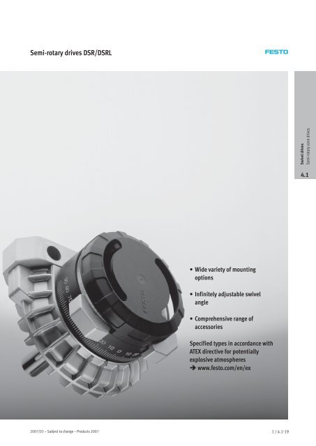
<strong>Semi</strong>-<strong>rotary</strong><strong>drives</strong><strong>DSR</strong>/<strong>DSR</strong>L<br />
Swivel <strong>drives</strong><br />
<strong>Semi</strong>-<strong>rotary</strong> vane <strong>drives</strong><br />
4.1<br />
• Wide variety of mounting<br />
options<br />
• Infinitely adjustable swivel<br />
angle<br />
• Comprehensive range of<br />
accessories<br />
Specified types in accordance with<br />
ATEX directive for potentially<br />
explosive atmospheres<br />
www.festo.com/en/ex<br />
2007/03 – Subject to change – Products 2007 1 / 4.1-19
<strong>Semi</strong>-<strong>rotary</strong><strong>drives</strong><strong>DSR</strong>/<strong>DSR</strong>L<br />
Features<br />
Swivel <strong>drives</strong><br />
<strong>Semi</strong>-<strong>rotary</strong> vane <strong>drives</strong><br />
4.1<br />
Brief description<br />
In these semi-<strong>rotary</strong> <strong>drives</strong>, the force<br />
is directly transmitted to the drive<br />
shaft via a <strong>rotary</strong> vane. The swivel<br />
angle is infinitely adjustable from<br />
0 … 184°<br />
(<strong>DSR</strong>L-10 and 12: 0 … 181°).<br />
The adjustable stop system is<br />
separate from the <strong>rotary</strong> vane so that<br />
any forces which occur are absorbed<br />
by the stop blocks. The impacts are<br />
cushioned at the end positions by<br />
flexible plastic plates.<br />
<strong>DSR</strong>L-…-FW<br />
This design with hollow flanged shaft<br />
permits the passage of liquid or<br />
gaseous media, or even tubing or<br />
wiring. The force is transmitted<br />
directly and backlash-free via a<br />
splined shaft.<br />
Mass moment of inertia calculation<br />
tool<br />
www.festo.com/en/engineering<br />
1 / 4.1-20<br />
Products 2007 – Subject to change – 2007/03
<strong>Semi</strong>-<strong>rotary</strong><strong>drives</strong><strong>DSR</strong>/<strong>DSR</strong>L<br />
Features<br />
Mounting options<br />
Without mounting attachments<br />
Direct mounting<br />
With mounting attachments<br />
for <strong>DSR</strong><br />
for <strong>DSR</strong>L<br />
Foot mounting HSR-…-FW Flange mounting FSR Push-on flange FWSR Foot mounting HSR-…-FW<br />
Swivel <strong>drives</strong><br />
<strong>Semi</strong>-<strong>rotary</strong> vane <strong>drives</strong><br />
4.1<br />
Freewheel unit for synchronous movements<br />
The freewheel unit is an attachment<br />
which is fitted to the drive shaft of the<br />
semi-<strong>rotary</strong> drive <strong>DSR</strong>. The freewheel<br />
unit converts the oscillating <strong>rotary</strong><br />
movement of the semi-<strong>rotary</strong> drive<br />
into a synchronous, indexing<br />
movement. The movement of the<br />
semi-<strong>rotary</strong> drive shaft only occurs in<br />
the working directions left or right.<br />
This permits infinitely adjustable feed<br />
movements.<br />
The minimum possible swivel angle is<br />
0.4°. Switching accuracy is also<br />
dependent upon switching speed and<br />
load.<br />
-H- Note<br />
Theloadmustbestopped<br />
externally!<br />
FLSR-…-L (left-hand)<br />
Viewed from the drive shaft side,<br />
rotation counter-clockwise.<br />
FLSR-…-R (right-hand)<br />
Viewed from the drive shaft side,<br />
rotation clockwise.<br />
Accessories<br />
Speed regulation<br />
1 / 4.1-38<br />
FLSR with semi-<strong>rotary</strong> drive<br />
Sample applications with hollow flanged shaft in <strong>DSR</strong>L<br />
Air blast Vacuum Electrical lines Water, coolant, oil, glue, etc.<br />
2007/03 – Subject to change – Products 2007 1 / 4.1-21
<strong>Semi</strong>-<strong>rotary</strong><strong>drives</strong><strong>DSR</strong>/<strong>DSR</strong>L<br />
Peripherals overview and type codes<br />
aC<br />
5<br />
aB<br />
Swivel <strong>drives</strong><br />
<strong>Semi</strong>-<strong>rotary</strong> vane <strong>drives</strong><br />
4.1<br />
<strong>DSR</strong>L<br />
6<br />
aJ<br />
7<br />
aA<br />
8<br />
9<br />
1<br />
<strong>DSR</strong><br />
2<br />
3<br />
4<br />
1<br />
aD<br />
aE<br />
1 / 4.1-22<br />
Products 2007 – Subject to change – 2007/03
<strong>Semi</strong>-<strong>rotary</strong><strong>drives</strong><strong>DSR</strong>/<strong>DSR</strong>L<br />
Peripherals overview and type codes<br />
Mounting attachments and accessories<br />
Brief description <strong>DSR</strong> <strong>DSR</strong>L Page<br />
1 Foot mounting<br />
HSR-…-FW<br />
On drive shaft side<br />
<br />
<br />
1/4.1-30<br />
2 Freewheel unit<br />
FLSR-…-L/R<br />
For spigot shaft, clockwise or anti-clockwise rotation optional<br />
–<br />
1/4.1-32<br />
3 Flange mounting<br />
FSR<br />
On drive shaft side<br />
–<br />
1/4.1-30<br />
4 Push-on flange<br />
FWSR<br />
5 Mounting kit<br />
WSR-…<br />
6 Mounting kit<br />
WSR-12 … 40<br />
7 Mounting kit<br />
WSR-10/12-K<br />
8 Micro switch<br />
S-3-BE-SW<br />
For spigot shaft<br />
For proximity sensor SIEN<br />
For micro switch SR-3-E-SW, S-3-E and micro stem actuated valve<br />
SO-3-PK-3-B, S-3-PK-3-B<br />
For micro switch S-3-BE-SW, S-3-BE<br />
Electric, with cable, splash-proof<br />
–<br />
<br />
<br />
<br />
<br />
1/4.1-31<br />
1/4.1-35<br />
1/4.1-34<br />
1/4.1-34<br />
1/4.1-37<br />
Swivel <strong>drives</strong><br />
<strong>Semi</strong>-<strong>rotary</strong> vane <strong>drives</strong><br />
4.1<br />
9 Micro switch<br />
S-3-BE<br />
Electric, with push-in connector<br />
<br />
<br />
1/4.1-37<br />
aJ<br />
Micro switch<br />
SR-3-E-SW<br />
Electric, with roller lever and cable, splash-proof<br />
<br />
<br />
1/4.1-37<br />
aA<br />
Micro switch<br />
S-3-E<br />
Electric, screw connector<br />
<br />
<br />
1/4.1-37<br />
aB<br />
Micro stem actuated valve<br />
SO-3-PK-3-B, S-3-PK-3-B<br />
Pneumatic, either normally opened or normally closed<br />
<br />
<br />
1/4.1-38<br />
aC<br />
Proximity sensors<br />
SIEN<br />
Inductive<br />
<br />
<br />
1/4.1-38<br />
aD<br />
Push-in L-fitting<br />
QSL<br />
For connecting compressed air tubing with standard external<br />
diameters<br />
<br />
<br />
Volume 3<br />
aE<br />
One-way flow control valve<br />
GRLA<br />
For speed regulation<br />
<br />
<br />
1/4.1-38<br />
u<br />
<strong>DSR</strong>L — 10 — 180 — P — FW<br />
Type<br />
Double-acting<br />
<strong>DSR</strong> <strong>Semi</strong>-<strong>rotary</strong> drive with spigot shaft<br />
<strong>DSR</strong>L <strong>Semi</strong>-<strong>rotary</strong> drive, with flanged, hollow drive<br />
shaft<br />
Piston ∅ [mm]<br />
Swivel angle [°]<br />
Cushioning<br />
P<br />
Non-adjustable at either end<br />
Shaft<br />
FW<br />
Spigot shaft<br />
Drive shaft<br />
2007/03 – Subject to change – Products 2007 1 / 4.1-23
<strong>Semi</strong>-<strong>rotary</strong><strong>drives</strong><strong>DSR</strong>/<strong>DSR</strong>L<br />
Technical data<br />
Function<br />
Variants<br />
With spigot shaft<br />
With hollow flanged shaft<br />
-N- Diameter<br />
10 … 40 mm<br />
-O- Force<br />
0.5 … 20 Nm<br />
<strong>DSR</strong><br />
<strong>DSR</strong>L<br />
Swivel <strong>drives</strong><br />
<strong>Semi</strong>-<strong>rotary</strong> vane <strong>drives</strong><br />
4.1<br />
-W- www.festo.com/en/<br />
Spare_parts_service<br />
General technical data<br />
Piston ∅ 10 12 16 25 32 40<br />
Pneumatic connection M3 M5 M5 M5 Gx G¼<br />
Design<br />
<strong>Semi</strong>-<strong>rotary</strong> actuator with vane drive<br />
Cushioning<br />
Non-adjustable at either end<br />
Position sensing<br />
Electrical<br />
Pneumatic<br />
Inductive<br />
Type of mounting<br />
Via through-holes<br />
Via accessories<br />
Mounting position<br />
Any<br />
Max. swivel angle 0 … 181 ° 0…184°<br />
-H- Note: This product conforms with the ISO 1179-1 standard and the ISO 228-1 standard.<br />
Operating and environmental conditions<br />
Piston ∅ 10 12 16 25 32 40<br />
Operating medium<br />
Filtered compressed air, lubricated or unlubricated<br />
Operating pressure [bar] 2.5 … 8 2…8 1.5 … 8<br />
Temperature range 1) [°C] –10 … +60<br />
1) Note operating range of proximity sensors<br />
Forces and torques<br />
Piston ∅ 10 12 16 25 32 40<br />
Torque at 6 bar [Nm] 0.5 1 2 5 10 20<br />
Max. swivelling frequency 1) [Hz] 3<br />
Max. perm. radial load 2) [N] 30 45 75 120 200 350<br />
Max. perm. axial load 2) [N] 10 18 30 50 75 120<br />
Max. perm. mass moment of inertia 2) Diagrams 1 / 4.1-26<br />
1) Please observe the max. permissible mass moments of inertia 1 / 4.1-26<br />
2) On the drive shaft at maximum frequency<br />
1 / 4.1-24<br />
Products 2007 – Subject to change – 2007/03
<strong>Semi</strong>-<strong>rotary</strong><strong>drives</strong><strong>DSR</strong>/<strong>DSR</strong>L<br />
Technical data<br />
Materials<br />
Sectional view<br />
5<br />
4<br />
1<br />
3<br />
2<br />
Swivel <strong>drives</strong><br />
<strong>Semi</strong>-<strong>rotary</strong> vane <strong>drives</strong><br />
4.1<br />
Rotary actuator<br />
1 Housing Die-cast zinc<br />
2 Drive shaft Nickel plated steel<br />
3 Rotary vane Plastic<br />
4 Trip cam Sintered steel, nickel plated<br />
5 Cover cap Plastic<br />
– Seals Nitrile rubber<br />
Weights [g]<br />
Piston ∅ 10 12 16 25 32 40<br />
<strong>DSR</strong>-…-P 100 200 310 540 1,285 2,400<br />
<strong>DSR</strong>L-…-FW 140 240 350 610 1,390 2,700<br />
2007/03 – Subject to change – Products 2007 1 / 4.1-25
<strong>Semi</strong>-<strong>rotary</strong><strong>drives</strong><strong>DSR</strong>/<strong>DSR</strong>L<br />
Technical data<br />
Max. permissible mass moment of inertia<br />
Mass moment of inertia m as a function of swivel time S and swivel angle<br />
<strong>DSR</strong>/<strong>DSR</strong>L-10 <strong>DSR</strong>/<strong>DSR</strong>L-12 <strong>DSR</strong>/<strong>DSR</strong>L-16<br />
Swivel <strong>drives</strong><br />
<strong>Semi</strong>-<strong>rotary</strong> vane <strong>drives</strong><br />
m [kgm 2 x10 –4 ]<br />
S[s]<br />
m [kgm 2 x10 –4 ]<br />
S[s]<br />
m [kgm 2 x10 –4 ]<br />
S[s]<br />
4.1<br />
<strong>DSR</strong>/<strong>DSR</strong>L-25 <strong>DSR</strong>/<strong>DSR</strong>L-32 <strong>DSR</strong>/<strong>DSR</strong>L-40<br />
m [kgm 2 x10 –4 ]<br />
m [kgm 2 x10 –4 ]<br />
m [kgm 2 x10 –4 ]<br />
S[s]<br />
S[s]<br />
S[s]<br />
Mass moment of inertia calculation<br />
tool<br />
www.festo.com/en/engineering<br />
.........<br />
Swivel angle 90°<br />
Swivel angle 120°<br />
Swivel angle 180°<br />
Assembly instructions:<br />
Stop<br />
∅ Stop radius Force<br />
If the listed maximum permissible<br />
mass moment of inertia is exceeded,<br />
the maximum force. Due to the<br />
flexibility of the stops, a precise end<br />
[mm]<br />
r min<br />
[mm] [N]<br />
external stops must be attached.<br />
position can only be achieved using<br />
10 13 60<br />
Please note:<br />
external stops. 12 15 90<br />
The stop must not be less than the<br />
16 17 160<br />
minimum i radius to the drive shaft<br />
25 21 320<br />
(r min ). The stop force must not exceed 32 28 480<br />
40 40 650<br />
-H- Note<br />
When throttling the semi-<strong>rotary</strong><br />
<strong>drives</strong> to swivelling speeds under<br />
180°/s, the <strong>drives</strong> must be operated<br />
at a pressure of at least 6 bar. A<br />
constant speed fluctuation of ±30 %<br />
is to be expected. The flutters and the<br />
swivelling times shown in the<br />
diagrams can only be improved by<br />
using flow control valves.<br />
1 / 4.1-26<br />
Products 2007 – Subject to change – 2007/03
<strong>Semi</strong>-<strong>rotary</strong><strong>drives</strong><strong>DSR</strong>/<strong>DSR</strong>L<br />
Technical data<br />
Dimensions<br />
<strong>DSR</strong><br />
Download CAD data www.festo.com/en/engineering<br />
-H- Note<br />
The swivel angle is 180° and pressure-dependent.<br />
The cushioning<br />
angle on each side is approx. 1.6°<br />
maximum at 8 bar.<br />
If after the swivel process, the<br />
kinetic energy is converted by<br />
cushioning, the drive shaft swivels<br />
back by a corresponding angle.<br />
Thestopsmustnotberemovedas<br />
the <strong>rotary</strong> vane is not suitable for<br />
end-position limiting. The cover cap<br />
is equipped with an angle scale for<br />
adjusting.<br />
Swivel <strong>drives</strong><br />
<strong>Semi</strong>-<strong>rotary</strong> vane <strong>drives</strong><br />
4.1<br />
When attaching additional<br />
components to the drive shaft, the<br />
maximum permissible tightening<br />
torqueoftheboltatD4mustnotbe<br />
exceeded.<br />
1 Angle scale for swivel angle<br />
reading<br />
2 Woodruff key position at 0 ° 3 Supply port<br />
∅<br />
[mm]<br />
B1 B2 B3 D1<br />
∅<br />
g7<br />
D2<br />
∅<br />
D3<br />
∅<br />
h8<br />
D4 E1 E2 H1 H2 H3 L1 L2<br />
10 22 32 53 6 12 20 M2.5 M3 M3 19.4 15.5 38.8 57 22.4<br />
12 26 40 65 8 16 22 M3 M5 M3 23.5 18.5 48 65.6 25.5<br />
16 30 46 78 10 17 24 M3 M5 M3 27 20.5 56.5 75.8 29<br />
25 42 60 98 12 18 28 M4 M5 M4 30 23 68.1 94.5 35.4<br />
32 54 80 130 16 27 42 M5 Gx M4 43 34 92 125.5 50<br />
40 70 100 160 20 36 52 M6 G¼ M4 53 40 121 162 60<br />
∅<br />
[mm]<br />
L3 L4 L5 L6 L7 S1 S2 T1 T2 X Woodruff key to DIN Tightening torque<br />
6885 1) at D4<br />
[Nm]<br />
10 6.5 4.5 15.1 2.2 2 3.4 6 6.8 7 0.35 A2x2x12 0.7<br />
12 5.5 3.5 18 2.1 2.5 4.4 8 8.8 9 0.35 A2x2x16 1.2<br />
16 6 3.5 22.5 2.1 – 5.5 10 11.2 9 0.35 A3x3x18 1.2<br />
25 5.4 3 30 4 – 7 11 13.5 10 0.4 A4x4x25 5.5<br />
32 10 7 36 4 – 8.5 15 18 12.5 0.45 A5x5x36 5.5<br />
40 10 6 50 4 – 8.5 15 22.5 16 0.5 A6x6x45 5.5<br />
1) included in scope of delivery<br />
-H- Note: This product conforms with the ISO 1179-1 standard and the ISO 228-1 standard.<br />
2007/03 – Subject to change – Products 2007 1 / 4.1-27
<strong>Semi</strong>-<strong>rotary</strong><strong>drives</strong><strong>DSR</strong>/<strong>DSR</strong>L<br />
Technical data<br />
Dimensions<br />
<strong>DSR</strong>L<br />
Download CAD data www.festo.com/en/engineering<br />
-H- Note<br />
Swivel <strong>drives</strong><br />
<strong>Semi</strong>-<strong>rotary</strong> vane <strong>drives</strong><br />
4.1<br />
The swivel angle is 180° and pressure-dependent.<br />
The cushioning<br />
angleoneachsideisapprox.1.6°<br />
maximum at 8 bar.<br />
If after the swivel process, the<br />
kinetic energy is converted by<br />
cushioning, the drive shaft swivels<br />
back by a corresponding angle.<br />
Thestopsmustnotberemovedas<br />
the <strong>rotary</strong> vane is not suitable for<br />
end-position limiting. The cover cap<br />
is equipped with an angle scale for<br />
adjusting.<br />
When attaching additional<br />
components to the drive flange, the<br />
maximum permissible tightening<br />
torqueoftheboltatD4mustnotbe<br />
exceeded.<br />
1 Angle scale for swivel angle<br />
reading<br />
2 Position of marking at angle<br />
scale 0°<br />
3 Supply port<br />
4 Through-hole<br />
∅<br />
[mm]<br />
B1 B2 B3 D1<br />
∅<br />
g7<br />
D2<br />
∅<br />
D3<br />
∅<br />
h8<br />
D4<br />
D5<br />
∅<br />
f8<br />
D6<br />
∅<br />
D7<br />
∅<br />
H13<br />
D8<br />
∅<br />
min.<br />
E1 E2 E3 H1<br />
10 22 32 53 30 10 20 M3 11 21 3.4 1.5 M3 M3 M3 19.4<br />
12 26 40 65 33 13 22 M3 14 25 3.4 1.5 M5 M3 M3 23.5<br />
16 30 46 78 38 14 24 M5 16 28 4.5 3.5 M5 M3 M4 27<br />
25 42 60 98 46 17 28 M5 20 35 5.5 3.5 M5 M4 M5 30<br />
32 54 80 130 60 24 42 Gx 28 45 6.5 7 Gx M4 M6 43<br />
40 70 100 160 70 30 52 Gx 36 54 9 7 G¼ M4 M8 53<br />
∅<br />
[mm]<br />
H2 H3 L1 L2 L3 L4 L5 L6 L7 L8 S1 S2 T1 X Tightening torque<br />
at D4<br />
[Nm]<br />
10 15.5 38.8 49 14 12.3 4.5 15.1 3 2.2 2 3.4 6 5 0.35 0.7<br />
12 18.5 48 54.2 13.5 11.5 3.5 18 3 2.1 2.5 4.4 8 5 0.35 1.2<br />
16 20.5 56.5 64.7 16 14 3.5 22.5 4 2.1 – 5.5 10 6 0.35 1.2<br />
25 23 68.1 78 18.5 15.5 3 30 4.5 4 – 7 11 6 0.4 5.5<br />
32 34 92 102.8 26 22 7 36 6 4 – 8.5 15 8 0.45 5.5<br />
40 40 121 134.5 31 26 6 50 7.5 4 – 8.5 15 8 0.5 5.5<br />
-H- Note: This product conforms with the ISO 1179-1 standard and the ISO 228-1 standard.<br />
1 / 4.1-28<br />
Products 2007 – Subject to change – 2007/03
<strong>Semi</strong>-<strong>rotary</strong><strong>drives</strong><strong>DSR</strong>/<strong>DSR</strong>L<br />
Technical data<br />
Ordering data<br />
Rotary actuator Design ∅<br />
Part No. Type<br />
[mm]<br />
<strong>DSR</strong>-…-P<br />
With spigot shaft 10 33 297 <strong>DSR</strong>-10-180-P<br />
12 11 909 <strong>DSR</strong>-12-180-P<br />
16 11 910 <strong>DSR</strong>-16-180-P<br />
25 11 911 <strong>DSR</strong>-25-180-P<br />
32 11 912 <strong>DSR</strong>-32-180-P<br />
40 13 467 <strong>DSR</strong>-40-180-P<br />
<strong>DSR</strong>L-…-P-FW<br />
With hollow flanged shaft 10 33 296 <strong>DSR</strong>L-10-180-P-FW<br />
12 30 654 <strong>DSR</strong>L-12-180-P-FW<br />
16 30 655 <strong>DSR</strong>L-16-180-P-FW<br />
25 30 656 <strong>DSR</strong>L-25-180-P-FW<br />
32 30 657 <strong>DSR</strong>L-32-180-P-FW<br />
40 30 658 <strong>DSR</strong>L-40-180-P-FW<br />
Swivel <strong>drives</strong><br />
<strong>Semi</strong>-<strong>rotary</strong> vane <strong>drives</strong><br />
4.1<br />
2007/03 – Subject to change – Products 2007 1 / 4.1-29
<strong>Semi</strong>-<strong>rotary</strong><strong>drives</strong><strong>DSR</strong>/<strong>DSR</strong>L<br />
Accessories<br />
Foot mounting HSR-…-FW<br />
Material:<br />
Steel<br />
Swivel <strong>drives</strong><br />
<strong>Semi</strong>-<strong>rotary</strong> vane <strong>drives</strong><br />
4.1<br />
Dimensions and ordering data<br />
For ∅ B1 B2 D1 D2 D10 H1 H2 L1 L2 L3 N1 CRC 1) Weight Part No. Type<br />
[mm]<br />
∅<br />
H13<br />
[g]<br />
10 53.5 43 3.5 2 20 4 53 11 17 21 34 2 61 33 317 HSR-10-FW<br />
12 64 52 3.5 2 22 4 63 11 17 21 40 2 87 30 923 HSR-12-FW<br />
16 77 63 5.7 2 24 5 71 14 22 26.5 44 2 170 30 924 HSR-16-FW<br />
25 97 80 6.8 3 28 5 76 16 28 34 47 2 235 30 925 HSR-25-FW<br />
32 129 105 8.8 4 42 8 108 20 34 43 66 2 660 30 926 HSR-32-FW<br />
40 159 130 8.8 5 52 8 134 25 42 52 81 2 1,040 30 927 HSR-40-FW<br />
1) Corrosion resistance class 2 according to Festo standard 940 070<br />
Components requiring moderate corrosion resistance. Externally visible parts with primarily decorative surface requirements which are in direct contact with a surrounding industrial atmosphere or media such as<br />
cooling or lubricating agents<br />
Flange mounting FSR<br />
Material:<br />
Aluminium die-cast<br />
1 Max. length for centring spigot<br />
Dimensions and ordering data<br />
For ∅<br />
[mm]<br />
B3 B4 D3<br />
∅<br />
min.<br />
D4<br />
D5<br />
∅<br />
H13<br />
D6<br />
∅<br />
H13<br />
H3<br />
L4<br />
max.<br />
N2 R CRC 1) Weight<br />
[g]<br />
Part No.<br />
10 28 46 13 M3 3.4 6.5 7 2 20 18 2 22 34 480 FSR-10<br />
12 31 54 17 M3 3.4 6.5 7 2 22 20.5 2 32 14 658 FSR-12<br />
16 35 62 19 M4 4.5 8.5 8 2 26.5 23.5 2 50 13 236 FSR-16<br />
25 40 76 21 M5 5.5 10.4 8 2.5 29 27 2 70 13 237 FSR-25<br />
32 56 100 32 M6 6.6 12.4 12 2.5 42 36 2 180 13 238 FSR-32<br />
40 72 120 37 M8 9 16.4 14 4 52 46 2 300 14 655 FSR-40<br />
Type<br />
1) Corrosion resistance class 2 according to Festo standard 940 070<br />
Components requiring moderate corrosion resistance. Externally visible parts with primarily decorative surface requirements which are in direct contact with a surrounding industrial atmosphere or media such as<br />
cooling or lubricating agents<br />
1 / 4.1-30<br />
Products 2007 – Subject to change – 2007/03
<strong>Semi</strong>-<strong>rotary</strong><strong>drives</strong><strong>DSR</strong>/<strong>DSR</strong>L<br />
Accessories<br />
Push-on flange FWSR<br />
Thepermissibletighteningtorque<br />
may not be exceeded when installing<br />
the push-on flange FWSR on the drive<br />
shaft.<br />
Material:<br />
Wrought aluminium alloy, anodised<br />
Copper, PTFE and silicone free<br />
Dimensions and ordering data<br />
For ∅<br />
[mm]<br />
B5 D4 D5<br />
∅<br />
H13<br />
D7<br />
∅<br />
f8<br />
D8 D9 L5 L6 L7 Tightening<br />
torque<br />
[Nm]<br />
CRC 1)<br />
Weight<br />
[g]<br />
Part No.<br />
10 21 M3 3.4 11 30 12 22 3 1.6 0.7 2 10 32 798 FWSR-10<br />
12 25 M3 3.4 14 35 15 25 3 3 1.2 2 19 14 659 FWSR-12<br />
16 28 M4 4.5 16 40 17 28 5 3 1.2 2 30 13 239 FWSR-16<br />
25 35 M5 5.5 20 50 23 38 8 3 5.5 2 70 13 240 FWSR-25<br />
32 45 M6 6.6 28 60 28 48 10 4 5.5 2 120 13 241 FWSR-32<br />
40 54 M8 9 36 70 38 60 11 5 5.5 2 240 14 656 FWSR-40<br />
Type<br />
Swivel <strong>drives</strong><br />
<strong>Semi</strong>-<strong>rotary</strong> vane <strong>drives</strong><br />
4.1<br />
1) Corrosion resistance class 2 according to Festo standard 940 070<br />
Components requiring moderate corrosion resistance. Externally visible parts with primarily decorative surface requirements which are in direct contact with a surrounding industrial atmosphere or media such as<br />
cooling or lubricating agents<br />
2007/03 – Subject to change – Products 2007 1 / 4.1-31
<strong>Semi</strong>-<strong>rotary</strong><strong>drives</strong><strong>DSR</strong>/<strong>DSR</strong>L<br />
Accessories<br />
Freewheel unit FLSR<br />
Material:<br />
Housing: Aluminium die-cast<br />
Sleeve, shaft: Case-hardened steel<br />
Seal, cap: Nitrile rubber<br />
Swivel <strong>drives</strong><br />
<strong>Semi</strong>-<strong>rotary</strong> vane <strong>drives</strong><br />
4.1<br />
General technical data<br />
Piston ∅ 10 12 16 25 32 40<br />
Design<br />
Freewheel unit as attachment<br />
Rotation angle<br />
Infinitely adjustable steps (independent of rotation angle)<br />
Applied radial load [N] 52 77 160 350 200 350<br />
Applied axial load [N] 30 50 100 200 75 120<br />
Max. torque [Nm] 0.7 1.3 2.7 6.6 13.3 26.7<br />
Frequency<br />
3Hz(-H- Theloadmustbestoppedexternally!)<br />
Temperature range [°C] –10 … +60<br />
Direction of rotation<br />
The freewheel unit blocks one of the<br />
two possible swivel directions of the<br />
DSM swivel module.<br />
FLSM-…-R, right-hand (clockwise) rotation<br />
FLSM-…-L, left-hand (counter-clockwise) rotation<br />
1 1<br />
1 Viewed towards drive shaft<br />
1 / 4.1-32<br />
Products 2007 – Subject to change – 2007/03
<strong>Semi</strong>-<strong>rotary</strong><strong>drives</strong><strong>DSR</strong>/<strong>DSR</strong>L<br />
Accessories<br />
Dimensions and ordering data<br />
For ∅<br />
[mm]<br />
B4 B5 B6 D1<br />
∅<br />
g7<br />
D3<br />
∅<br />
h8<br />
D4<br />
D5<br />
∅<br />
H13<br />
D6 H4 H5 L6 L7 L8 L9 L10<br />
10 38 45 38.5 6 20 – 3.3 M3 20 42.5 3.5 4.2 41.5 20.2 23<br />
12 42 49 41.5 8 25 M3 3.3 M3 24 48.5 3.5 4.5 47.3 24.5 25<br />
16 50 60 50 10 24 M3 4.5 M4 28 58 3.5 4.4 47 27.4 23.5<br />
25 60 75 60 12 28 M4 6.6 M6 31 68.5 3.5 4.1 48 34 24<br />
32 83 98 83 16 42 M5 6.6 M6 44 93 7.2 8.5 60 48.5 30<br />
40 96 114 96 20 52 M6 8.6 M8 54 111 6 8 75 58 38<br />
For ∅ T1 T2 T3 T4 T5 Woodruff key 1) CRC 2) Weight Direction of rotation Part No. Type<br />
to DIN 6885<br />
[mm]<br />
[g]<br />
10 6.8 8 8 5 8 A2x2x12 2 165 left-hand 33 298 FLSR-10-L<br />
right-hand 33 299 FLSR-10-R<br />
12 8.8 9 8 5 9 A2x2x16 2 225 left-hand 30 930 FLSR-12-L<br />
right-hand 30 929 FLSR-12-R<br />
16 11.2 11 10 8 11 A3x3x18 2 340 left-hand 15 281 FLSR-16-L<br />
right-hand 15 280 FLSR-16-R<br />
25 13.5 14 12 11 14 A4x4x25 2 500 left-hand 13 778 FLSR-25-L<br />
right-hand 13 730 FLSR-25-R<br />
32 18 16 12 11 16 A5x5x36 2 1140 left-hand 15 688 FLSR-32-L<br />
right-hand 15 687 FLSR-32-R<br />
40 22.5 21 15 11 21 A6x6x45 2 1800 left-hand 19 037 FLSR-40-L<br />
right-hand 19 036 FLSR-40-R<br />
Swivel <strong>drives</strong><br />
<strong>Semi</strong>-<strong>rotary</strong> vane <strong>drives</strong><br />
4.1<br />
1) included in scope of delivery<br />
2) Corrosion resistance class 2 according to Festo standard 940 070<br />
Components requiring moderate corrosion resistance. Externally visible parts with primarily decorative surface requirements which are in direct contact with a surrounding industrial atmosphere or media such as<br />
cooling or lubricating agents<br />
2007/03 – Subject to change – Products 2007 1 / 4.1-33
<strong>Semi</strong>-<strong>rotary</strong><strong>drives</strong><strong>DSR</strong>/<strong>DSR</strong>L<br />
Accessories<br />
Mounting kit<br />
WSR-10/12-K<br />
for micro switch S-3-BE, S-3-BE-SW<br />
Material:<br />
Steel<br />
Swivel <strong>drives</strong><br />
<strong>Semi</strong>-<strong>rotary</strong> vane <strong>drives</strong><br />
4.1<br />
Dimensions and ordering data<br />
For ∅<br />
B H1 H2 L3 CRC 1) Weight<br />
Part No.<br />
[mm]<br />
[g]<br />
10 15 1 22.2 47 2 11 33 414 WSR-10-K<br />
12 15 1 25.1 53 2 13 15 686 WSR-12-K<br />
Type<br />
1) Corrosion resistance class 2 according to Festo standard 940 070<br />
Components requiring moderate corrosion resistance. Externally visible parts with primarily decorative surface requirements which are in direct contact with a surrounding industrial atmosphere or media such as<br />
cooling or lubricating agents<br />
Mounting kit<br />
WSR-12 … 40<br />
for micro switch S-3-E, SR-3-E-SW and<br />
micro stem actuated valve<br />
S-3-PK-3-B, SO-3-PK-3-B<br />
Material:<br />
Steel<br />
Dimensions and ordering data<br />
For ∅ B1 B2 B3 H1 H2 L2 L3 CRC 1) Weight<br />
Part No.<br />
Type<br />
[mm]<br />
[g]<br />
12 5.8 23.4 4 1.5 23 14 79 2 12 15 684 WSR-12<br />
16 10 26.5 4.5 1.5 29.8 19 84.5 2 23 14 874 WSR-16<br />
25 12 29 2 1.5 38 24.5 90 2 26 14 796 WSR-25<br />
32 12 29 2 1.5 49.2 40.5 107 2 29 14 960 WSR-32<br />
40 12 29 2 1.5 68.7 52 118.5 2 32 14 961 WSR-40<br />
1) Corrosion resistance class 2 according to Festo standard 940 070<br />
Components requiring moderate corrosion resistance. Externally visible parts with primarily decorative surface requirements which are in direct contact with a surrounding industrial atmosphere or media such as<br />
cooling or lubricating agents<br />
1 / 4.1-34<br />
Products 2007 – Subject to change – 2007/03
<strong>Semi</strong>-<strong>rotary</strong><strong>drives</strong><strong>DSR</strong>/<strong>DSR</strong>L<br />
Accessories<br />
Mounting kit<br />
WSR-…-J<br />
for proximity sensors SIEN-M8<br />
WSR-…-J-M5<br />
for proximity sensors SIEN-M5<br />
Material:<br />
Steel<br />
Swivel <strong>drives</strong><br />
<strong>Semi</strong>-<strong>rotary</strong> vane <strong>drives</strong><br />
Dimensions and ordering data<br />
WSR-…-J<br />
4.1<br />
For ∅<br />
B4 H3 H4 L4 L5 CRC 1) Weight<br />
Part No.<br />
Type<br />
[mm]<br />
[g]<br />
16 13 1.5 35 52 27 2 12 14 873 WSR-16-J<br />
25 13 1.5 43.1 52 34 2 17 14 799 WSR-25-J<br />
32 13 1.5 54.3 64 48 2 18 14 962 WSR-32-J<br />
40 13 1.5 76.3 80 60 2 24 14 963 WSR-40-J<br />
WSR-…-J-M5<br />
For ∅<br />
B4 H3 H4 L4 L5 CRC 1) Weight<br />
Part No.<br />
Type<br />
[mm]<br />
[g]<br />
10 8 1 25.4 30 20 2 6 33 413 WSR-10-J-M5<br />
12 8 1 28.3 34 24.5 2 10 15 685 WSR-12-J-M5<br />
16 8 1 34.9 38 27 2 78 15 931 WSR-16-J-M5<br />
25 13 1.5 43 52 34 2 17 15 932 WSR-25-J-M5<br />
32 13 1.5 54.3 64 48 2 25 15 933 WSR-32-J-M5<br />
40 13 1.5 76.3 80 60 2 30 15 934 WSR-40-J-M5<br />
1) Corrosion resistance class 2 according to Festo standard 940 070<br />
Components requiring moderate corrosion resistance. Externally visible parts with primarily decorative surface requirements which are in direct contact with a surrounding industrial atmosphere or media such as<br />
cooling or lubricating agents<br />
2007/03 – Subject to change – Products 2007 1 / 4.1-35
<strong>Semi</strong>-<strong>rotary</strong><strong>drives</strong><strong>DSR</strong>/<strong>DSR</strong>L<br />
Accessories<br />
Electrical limit switch for end-position sensing<br />
Swivel <strong>drives</strong><br />
<strong>Semi</strong>-<strong>rotary</strong> vane <strong>drives</strong><br />
4.1<br />
The switching point may only be<br />
exceeded d by 0.5 mm in these<br />
electrical l limit i switches. Actuation<br />
only vertical to stem axis.<br />
Connection<br />
Contact rating<br />
Operating voltage<br />
S-3-BE S-3-BE-SW S-3-E SR-3-E-SW<br />
3push-inconnectors 3wires<br />
Screw connector 3wires<br />
(2.8x0.5 mm) (0.75 mm 2 )<br />
0.5 m long<br />
Table below<br />
250 V AC/250 V DC<br />
Line current ohmic load – – 6A/250VAC<br />
0.25 A/250 V DC<br />
Line current inductive load – – 2A/250VAC<br />
0.1 A/250 V DC<br />
Utilisation category AC 12/DC 12 (ohmic load)<br />
AC 14/DC 13 (inductive load)<br />
CE symbol<br />
Yes, as per EU Directive 73/23/EEC<br />
Protection class to EN 60 529 IP40 IP67 IP 00 IP65<br />
Temperature range –20 ... +85 °C –20 ... +80 °C<br />
Material<br />
Housing, cover: black plastic<br />
Weight 2g 16 g 7g 10 g<br />
5 A/250 V AC<br />
0.25 A /250 V DC<br />
2 A/250 V AC<br />
0.03 A/250 V DC<br />
S-3-BE, S-3-BE-SW<br />
Test symbols: Contact configuration: AC voltage<br />
S-3-BE:<br />
S-3-BE-SW:<br />
S-3-E:<br />
VDE-ÜG, UL, CSA,<br />
SEMKO<br />
VDE, SEV, SEMKO,<br />
BEAB<br />
VDE, ÖVE, SEMKO,<br />
SEV, UL, CSA<br />
Changeover switch<br />
black<br />
blue<br />
grey<br />
Voltage<br />
[V] ~<br />
12<br />
24<br />
60<br />
110<br />
220<br />
Resistance load<br />
[A]<br />
6<br />
3<br />
1<br />
0.5<br />
0.25<br />
Inductive load<br />
[A]<br />
6<br />
2<br />
0.5<br />
0.2<br />
0.1<br />
NC contact S-3-E DC AC DC AC<br />
black<br />
NO contact<br />
black<br />
blue<br />
grey<br />
12<br />
24<br />
60<br />
110<br />
220<br />
250<br />
6<br />
6<br />
1<br />
0.5<br />
0.25<br />
–<br />
–<br />
–<br />
–<br />
–<br />
–<br />
6<br />
6<br />
6<br />
0.5<br />
0.2<br />
0.1<br />
–<br />
SR-3-E-SW DC AC DC AC<br />
15<br />
30<br />
50<br />
75<br />
125<br />
250<br />
3<br />
3<br />
1<br />
0.25<br />
0.03<br />
0.03<br />
–<br />
–<br />
–<br />
–<br />
5<br />
5<br />
5<br />
5<br />
1<br />
0.75<br />
0.5<br />
0.25<br />
–<br />
–<br />
–<br />
–<br />
–<br />
2<br />
–<br />
–<br />
–<br />
–<br />
5<br />
5<br />
Pneumatic limit valve for end-position sensing<br />
S-3-PK-3-B/SO-3-PK-3-B<br />
S-... The switching point is pressure- Connection Barbed fitting for 3 mm plastic tubing<br />
dependent and deviates up to<br />
Nominal size 1.8 mm<br />
0.8 mm in the pressure e range from Standard nominal flow rate (1 > 2) 60 l/min<br />
0…8bar.Theswitchingpointmay Pressure range –0.95 ... +8 bar<br />
SO-...<br />
only be exceeded by 0.5 mm. The Actuating force at 6 bar 6N<br />
valve must not be used as a fixed Temperature range –10 ... +60 °C<br />
stopandshouldonlybeoperated p<br />
Materials Plastic, brass<br />
vertically to the stem. Weight 7g<br />
1 / 4.1-36<br />
Products 2007 – Subject to change – 2007/03
<strong>Semi</strong>-<strong>rotary</strong><strong>drives</strong><strong>DSR</strong>/<strong>DSR</strong>L<br />
Accessories<br />
Electrical limit switch for end-position sensing<br />
Micro switch<br />
S-3-BE<br />
Microswitchwithcable(splash-proof)<br />
S-3-BE-SW<br />
1 Switching point<br />
2 Normal position 3 Push-in connector<br />
Swivel <strong>drives</strong><br />
<strong>Semi</strong>-<strong>rotary</strong> vane <strong>drives</strong><br />
4.1<br />
1 Switching point<br />
2 Normal position<br />
Micro switch<br />
S-3-E<br />
1 Switching point<br />
2 Normal position<br />
Microswitchwithrollerlever<br />
(splash-proof)<br />
SR-3-E-SW<br />
1 Switching point<br />
2 Normal position<br />
Ordering data<br />
For ∅<br />
Electrical limit switches, splash-proof Design Part No. Type<br />
[mm]<br />
10 … 12 30 648 S-3-BE<br />
With cable 30 649 S-3-BE-SW<br />
16 … 40 With roller lever 7347 S-3-E<br />
14 797 SR-3-E-SW<br />
2007/03 – Subject to change – Products 2007 1 / 4.1-37
<strong>Semi</strong>-<strong>rotary</strong><strong>drives</strong><strong>DSR</strong>/<strong>DSR</strong>L<br />
Accessories<br />
Pneumatic limit valve for end-position sensing<br />
Micro stem actuated valve<br />
S-3-PK-3-B<br />
SO-3-PK-3-B<br />
Swivel <strong>drives</strong><br />
<strong>Semi</strong>-<strong>rotary</strong> vane <strong>drives</strong><br />
4.1<br />
Ordering data<br />
For ∅<br />
1 Barbed fittings for 3 mm plastic<br />
tubing<br />
2 Switching point min.<br />
Pneumatic limit switch Design Part No. Type<br />
1(P)= supplyport<br />
2 (A) = working or outlet line<br />
3 (R) = exhaust<br />
[mm]<br />
16 … 40 Normally closed 7843 S-3-PK-3-B<br />
Normally open 10 403 SO-3-PK-3-B<br />
Ordering data – Proximity sensors, inductive Technical data Volume 4<br />
For ∅ Remarks Connection Part No. Type<br />
10 … 40 For mounting kit WSR-…-J-M5 Cable 150 370 SIEN-M5B-PS-K-L<br />
Plug 150 371 SIEN-M5B-PS-S-L<br />
16 … 40 For mounting kit WRM-…-J Cable 150 386 SIEN-M8B-PS-K-L<br />
Plug 150 387 SIEN-M8B-PS-S-L<br />
Ordering data – Connecting cable<br />
Technical data www.festo.com/catalogue/nebu<br />
Electrical connection, left Electrical connection, right Cable length Part No. Type<br />
[m]<br />
Straight socket, M8x1, 3-pin Cable, open end, 3-wire 2,5 541 333 NEBU-M8G3-K-2.5-LE3<br />
5 541 334 NEBU-M8G3-K-5-LE3<br />
Angled socket, M8x1, 3-pin Cable, open end, 3-wire 2,5 541 338 NEBU-M8W3-K-2.5-LE3<br />
5 541 341 NEBU-M8W3-K-5-LE3<br />
Ordering data – One-way flow control valves Technical data Volume 2<br />
Connection Material Part No. Type<br />
Thread<br />
For tubing OD<br />
M3 3 Metal design 175 041 GRLA-M3-QS-3<br />
M5 3<br />
193 137 GRLA-M5-QS-3-D<br />
4 193 138 GRLA-M5-QS-4-D<br />
6 193 139 GRLA-M5-QS-6-D<br />
Gxx<br />
3 193 142 GRLA-x-QS-3-D<br />
4 193 143 GRLA-x-QS-4-D<br />
6 193 144 GRLA-x-QS-6-D<br />
8 193 145 GRLA-x-QS-8-D<br />
G¼¼<br />
6 193 146 GRLA-¼-QS-6-D<br />
8 193 147 GRLA-¼-QS-8-D<br />
10 193 148 GRLA-¼-QS-10-D<br />
1 / 4.1-38<br />
Products 2007 – Subject to change – 2007/03