Surge-Trap SPD Type 1 XT Installation Instructions - Mersen
Surge-Trap SPD Type 1 XT Installation Instructions - Mersen
Surge-Trap SPD Type 1 XT Installation Instructions - Mersen

Create successful ePaper yourself
Turn your PDF publications into a flip-book with our unique Google optimized e-Paper software.
INSTALLATION INSTRUCTIONS<br />
<strong>Surge</strong>-<strong>Trap</strong> ® <strong>Type</strong> 1 <strong>XT</strong> Series <strong>SPD</strong><br />
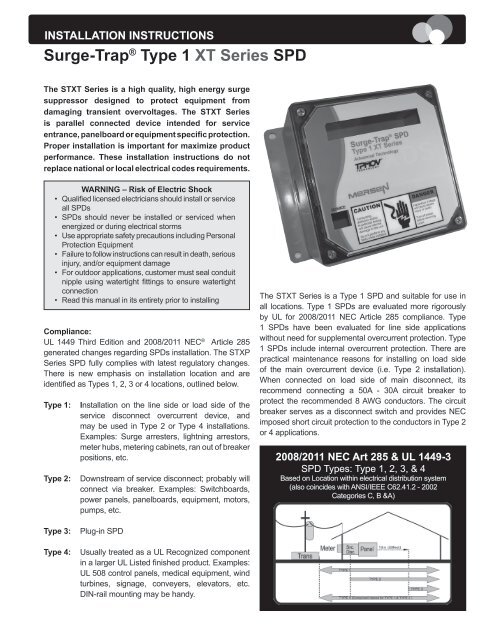
The ST<strong>XT</strong> Series is a high quality, high energy surge<br />
suppressor designed to protect equipment from<br />
damaging transient overvoltages. The ST<strong>XT</strong> Series<br />
is parallel connected device intended for service<br />
entrance, panelboard or equipment specific protection.<br />
Proper installation is important for maximize product<br />
performance. These installation instructions do not<br />
replace national or local electrical codes requirements.<br />
WARNING – Risk of Electric Shock<br />
• Qualified licensed electricians should install or service<br />
all <strong>SPD</strong>s<br />
• <strong>SPD</strong>s should never be installed or serviced when<br />
energized or during electrical storms<br />
• Use appropriate safety precautions including Personal<br />
Protection Equipment<br />
• Failure to follow instructions can result in death, serious<br />
injury, and/or equipment damage<br />
• For outdoor applications, customer must seal conduit<br />
nipple using watertight fittings to ensure watertight<br />
connection<br />
• Read this manual in its entirety prior to installing<br />
Compliance:<br />
UL 1449 Third Edition and 2008/2011 NEC ® Article 285<br />
generated changes regarding <strong>SPD</strong>s installation. The STXP<br />
Series <strong>SPD</strong> fully complies with latest regulatory changes.<br />
There is new emphasis on installation location and are<br />
identified as <strong>Type</strong>s 1, 2, 3 or 4 locations, outlined below.<br />
<strong>Type</strong> 1:<br />
<strong>Type</strong> 2:<br />
<strong>Installation</strong> on the line side or load side of the<br />
service disconnect overcurrent device, and<br />
may be used in <strong>Type</strong> 2 or <strong>Type</strong> 4 installations.<br />
Examples: <strong>Surge</strong> arresters, lightning arrestors,<br />
meter hubs, metering cabinets, ran out of breaker<br />
positions, etc.<br />
Downstream of service disconnect; probably will<br />
connect via breaker. Examples: Switchboards,<br />
power panels, panelboards, equipment, motors,<br />
pumps, etc.<br />
The ST<strong>XT</strong> Series is a <strong>Type</strong> 1 <strong>SPD</strong> and suitable for use in<br />
all locations. <strong>Type</strong> 1 <strong>SPD</strong>s are evaluated more rigorously<br />
by UL for 2008/2011 NEC Article 285 compliance. <strong>Type</strong><br />
1 <strong>SPD</strong>s have been evaluated for line side applications<br />
without need for supplemental overcurrent protection. <strong>Type</strong><br />
1 <strong>SPD</strong>s include internal overcurrent protection. There are<br />
practical maintenance reasons for installing on load side<br />
of the main overcurrent device (i.e. <strong>Type</strong> 2 installation).<br />
When connected on load side of main disconnect, its<br />
recommend connecting a 50A - 30A circuit breaker to<br />
protect the recommended 8 AWG conductors. The circuit<br />
breaker serves as a disconnect switch and provides NEC<br />
imposed short circuit protection to the conductors in <strong>Type</strong> 2<br />
or 4 applications.<br />
2008/2011 NEC Art 285 & UL 1449-3<br />
<strong>SPD</strong> <strong>Type</strong>s: <strong>Type</strong> 1, 2, 3, & 4<br />
Based on Location within electrical distribution system<br />
(also coincides with ANSI/IEEE C62.41.2 - 2002<br />
Categories C, B &A)<br />
<strong>Type</strong> 3:<br />
<strong>Type</strong> 4:<br />
Plug-in <strong>SPD</strong><br />
Usually treated as a UL Recognized component<br />
in a larger UL Listed finished product. Examples:<br />
UL 508 control panels, medical equipment, wind<br />
turbines, signage, conveyers, elevators, etc.<br />
DIN-rail mounting may be handy.
Specifications<br />
Temperature Operating<br />
Temperature Storage<br />
Wire Size & <strong>Installation</strong><br />
Torque<br />
Appropriate Circuit<br />
Breaker based on<br />
conductor size<br />
NEMA 250 Enclosure<br />
Rating<br />
-40 o C (-40 o F) to 60 o C<br />
(+140 o F)<br />
-55 o C (-67 o F) to 65 o C<br />
(+149 o F)<br />
8 AWG; 18 inch-pounds<br />
30A (<strong>SPD</strong> includes internal<br />
OCP)<br />
<strong>Type</strong> 4X with appropriate<br />
sealing<br />
Device Operation:<br />
<strong>SPD</strong>s sense overvoltage conditions and create a momentary<br />
short circuit to redirect harmful surge energy to earth ground,<br />
resetting automatically waiting for the next surge. Operation<br />
is similar to a pressure relief valve on a water heater: pressure<br />
builds, valve opens to relieve pressure, resets when pressure<br />
drops. <strong>SPD</strong>s are capable of repeating this function thousands<br />
of times before needing replacement.<br />
Voltage Rating & Application:<br />
Before installing your STXP, verify by nameplate voltage or<br />
model number that it has the same voltage rating as the<br />
power distribution system. DO NOT INSTALL ANY LOWER<br />
VOLTAGE RATED PRODUCT. See attached Data Sheet or<br />
call <strong>Mersen</strong> Technical Services at (978) 465-4853 for help.<br />
The system configuration is defined by the secondary<br />
windings of the transformer supplying the service entrance<br />
main or load. This includes whether or not the transformer<br />
windings are referenced to earth via a grounding conductor.<br />
The system configuration is not based on any specific load<br />
or equipment connection. <strong>SPD</strong>s should be installed per<br />
the distribution system, not per a load or motor’s wiring<br />
connection. For example: A 480V three phase motor<br />
appears to be connected in 480V Delta. In reality, the<br />
distribution system is configured as a 480Y/277V grounded<br />
Wye, with or without a neutral pulled to the motor or MCC.<br />
The system is a 480Y/277V Wye, even though the load<br />
is connected as a Delta. A grounded Wye has a defined<br />
reference to ground (i.e., neutral is bonded to ground). In<br />
contrast, some Delta systems are ungrounded, which have<br />
no reference to ground.<br />
WARNING <strong>SPD</strong>s on Ungrounded Systems:<br />
Caution – Ungrounded systems are inherently unstable<br />
and can produce excessively high line-to-ground voltages<br />
during certain fault conditions. During these fault conditions,<br />
any electrical equipment including <strong>SPD</strong>s, may be subjected<br />
to voltages which exceed their designed ratings. This<br />
information is being provided to the user so that an informed<br />
decision can be made before installing any electrical<br />
equipment on an ungrounded power system.<br />
ST<strong>XT</strong> Series <strong>SPD</strong>s have high a SCCR (short circuit<br />
current ratings) capacity including the lead conductors.<br />
Supplemental overcurrent protection is not required to<br />
protect your ST<strong>XT</strong> <strong>SPD</strong>. However, NEC ® convention<br />
requires that connecting conductors have overcurrent<br />
protection in <strong>Type</strong> 2 or 4 applications. Follow applicable<br />
codes. Your ST<strong>XT</strong> device features internal overcurrent and<br />
over-temperature protection that will disconnect effected<br />
surge suppression components at end of life. Power to the<br />
load is maintained but unprotected and the ST<strong>XT</strong> should<br />
be replaced as soon as possible. The ST<strong>XT</strong> <strong>SPD</strong> is factory<br />
sealed and contains no serviceable parts.<br />
Service Clearance:<br />
Service clearance is needed at the front of the <strong>XT</strong> Series<br />
unit only, 36 inches minimum is the required distance for<br />
clearance pursuant to the NEC.<br />
Cascade <strong>Surge</strong> Protection:<br />
For optimum surge protection, cascade or staged surge<br />
suppression should be implemented at the service entrance<br />
and downstream locations as appropriate. Known or<br />
expected surge sources, as well as sensitive loads, should<br />
also have localized surge suppression. For interconnected<br />
electronic loads (data cabling), <strong>SPD</strong>s should also be utilized<br />
to protect the devices on either end of the interconnecting<br />
data cables.<br />
System Grounding:<br />
Equipment grounding conductor must be used on all electrical<br />
circuits connected to the <strong>SPD</strong>. For best performance,<br />
use single point ground system where service entrance<br />
grounding electrode system is connected and bonded to all<br />
other available electrodes, building steel, metal water pipes,<br />
driven rods, etc. For sensitive electronics and computer<br />
systems, we recommend that the ground impedance<br />
measurement be as low as possible. When metallic raceway<br />
is used as an additional grounding conductor, an insulated<br />
grounding conductor should be run inside the raceway and<br />
sized per the NEC. Adequate electrical continuity must be<br />
maintained at all raceway connections. Do not use isolating<br />
bushings to interrupt a metallic raceway run.<br />
A separate isolated ground for the <strong>SPD</strong> is NOT<br />
recommended. Proper equipment connections to grounding<br />
system and ground grid continuity should be verified via<br />
inspections and testing on a regular basis as part of a<br />
comprehensive electrical maintenance program. On 4-Wire<br />
Power Systems, neutral to ground bonding (Main Bonding<br />
Jumper) must be installed per the NEC. Failure to do so<br />
WILL damage <strong>SPD</strong>s.<br />
2
INSTALLATION:<br />
Plan your installation and accomplish the following:<br />
• Meet all National and Local codes (NEC ® Article 285<br />
and UL 1449 address <strong>SPD</strong>s).<br />
• Confirm System voltage to <strong>SPD</strong> voltage (120V <strong>SPD</strong> will<br />
fail instantly on 240V, 277V, etc.).<br />
• Mount STXP as close to panel or equipment as possible,<br />
keeping leads as short as possible.<br />
• Ensure leads are as short and straight as possible,<br />
including neutral and ground. If using a breaker, use a<br />
breaker position closest to <strong>SPD</strong> and panel’s neutral &<br />
ground.<br />
• If using a breaker, recommended breaker size is 50A -<br />
30A due to recommended 8 AWG conductors.<br />
• Make sure system is grounded per NEC and clear of<br />
faults before energizing <strong>SPD</strong>.<br />
• Never Hi-Pot test any <strong>SPD</strong>. Product will fail prematurely.<br />
1. Use voltmeter to check voltages and ensure correct<br />
<strong>SPD</strong>. See Data Sheet for specs & wire-outs.<br />
2. Determine mounting method (See Figure 2) – weather<br />
resistant equipment may be required.<br />
3. If <strong>SPD</strong> has optional Dry Contact, pre-plan its installation.<br />
4. Remove power from panel/source. Confirm panel and<br />
all sources are de-energized.<br />
5. Identify breaker location and <strong>SPD</strong> location. Position<br />
<strong>SPD</strong> such that front panel is visible.<br />
6. Mount <strong>SPD</strong> – weather resistant applications require<br />
additional sealing, o-rings, etc. (not included).<br />
• Remove an appropriately sized knockout from panel.<br />
• Connect conductors as appropriate – short and<br />
straight as possible (Hi-Legs are Phase B).<br />
7. Label or mark conductors as appropriate (neutral:<br />
white, ground: green, energized: black, hi-leg: orange).<br />
8. Make sure system is bonded per NEC and is clear of<br />
hazards or faults before energizing (N-G bonding not<br />
per NEC will fail <strong>SPD</strong>s: #1 cause of <strong>SPD</strong> failures).<br />
9. Energize and confirm proper operation of green<br />
indicators and/or options.<br />
Connecting Optional Form C Dry Contact & Audible Alarm:<br />
Three (3) 3’ (~1m) 18 AWG wires are included through the<br />
nipple with this option. (These are smaller than the 10 AWG<br />
<strong>SPD</strong> conductors.) Gray is Common, Blue is Normally Open<br />
and Blue is Normally Closed. (We generally recommend<br />
the Normally Closed configuration because it detects<br />
disconnected or failed wiring whereas normally open does<br />
not.) If the dry contacts are not utilized, insulate lead ends,<br />
coil and secure. Audible alarm will still function correctly.<br />
The contact is rated 250V, 5A. Higher energy applications<br />
require supplemental relaying. This option monitors<br />
suppression element condition and is not intended for use<br />
as phase loss or phase detection monitoring.<br />
NORMAL OPERATION:<br />
Phase indicator LEDs (Green)<br />
Each ST<strong>XT</strong> phase is equipped with Green LED. Should loss<br />
of surge protection occur on each phase, the Green LED<br />
will extinguish and the Red Service LED will flash. Every<br />
suppression component is monitored. Note -Green LED’s<br />
will go out due to loss of power or severe under voltage.<br />
Service LED (Red) Flashes due to problem. Red Service<br />
LED is slaved to Green LEDs and will illuminate when any<br />
Green LED extinguishes.<br />
Audible Alarm Option<br />
If equipped with optional Dry Contact and Audible Alarm,<br />
these options are slaved via logic to the Green LEDs. In<br />
the event of a problem, the dry contacts will change state<br />
and the audible alarm will sound. The audible alarm may be<br />
silenced by de-energizing the <strong>SPD</strong>.<br />
Dry Contact Option<br />
One set of Form C dry contacts are included with the<br />
Dry Contact option. Dry Contacts change state during<br />
inoperative conditions, including loss of power. Any status<br />
change can be monitored elsewhere via Dry Contacts.<br />
Note – Dry contacts are rated at max 5A at 240V AC or DC.<br />
Figure 3<br />
Dry Contacts<br />
Figure 2<br />
Mounting & Dimensions<br />
3<br />
Remote Monitor Accessory Option<br />
Remote Monitor is available for remote annunciation.<br />
It requires a standalone 120V power source (wall plug<br />
transformer) and uses one set of Form C dry contacts.<br />
The Remote Monitor can be configured to monitor several<br />
<strong>Mersen</strong> <strong>SPD</strong>s simultaneously. <strong>Installation</strong> is detailed in a<br />
separate document. Contact factory as appropriate.
Figure 4<br />
Flush Mount “/FM”<br />
(Preferred <strong>Installation</strong>)<br />
Maintenance:<br />
<strong>SPD</strong>s require minimal maintenance. Periodic inspection of<br />
diagnostic indicator is suggested to ensure proper operation.<br />
Supplemental <strong>Instructions</strong> for<br />
Deep Wall Mounting (Walls over 4” thick)<br />
Using the Enclosed Mounting Feet<br />
Troubleshooting & Service:<br />
Please contact <strong>Mersen</strong> Technical Services for any service<br />
related issues.<br />
Figure 5<br />
Conduit <strong>Installation</strong><br />
CORRECT INSTALLATION<br />
Threaded 6 Full Turns<br />
INCORRECT INSTALLATIONS<br />
Step 1<br />
Prepare Wall and <strong>SPD</strong><br />
Step 2<br />
Insert into Wall<br />
POOR ENGAGEMENT<br />
Conduit needs to be<br />
threaded in farther<br />
OVERTIGHTENED<br />
Stresses box, ONLY<br />
6 full turns required<br />
Figure 6<br />
Typical Panel <strong>Installation</strong><br />
To Protected Loads<br />
Step 3<br />
Mount the <strong>SPD</strong><br />
Step 4<br />
Mount the Lid<br />
• Use closest breaker to<br />
<strong>SPD</strong><br />
• Locate <strong>SPD</strong> close<br />
to intended breaker<br />
• Keep Leads Short as<br />
Possible<br />
• Avoid Sharp Bends<br />
Wall Cutout<br />
Front View<br />
6 3/4”<br />
Tall<br />
• Rotate <strong>XT</strong><br />
such that LED<br />
indicator is<br />
most visible<br />
6 1/16”<br />
Wide<br />
• Outdoor installation<br />
requires appropriate<br />
weather sealing at<br />
nipple (o-ring, sealing<br />
condulet, etc.)<br />
4
Figure 7<br />
Electrical Drawings for Customer Connections<br />
SPLIT<br />
2 Hots, 1 Neu, 1 Grnd<br />
WYE<br />
3 Hots, 1 Neu, 1 Grnd<br />
Figure 5<br />
HI-LEG DELTA (B High)<br />
3 Hots, (B HIGH),<br />
1 Neu, 1 Grnd<br />
DELTA & HRG WYE<br />
3 Hots, 1 Grnd<br />
SINGLE POLE<br />
1 Hot, 1 Neu, 1 Grnd<br />
CORNER GROUND<br />
DELTA (B grounded)<br />
2 Hots, 1 Grnd<br />
5
European Authorized Representative:<br />
Obelis S.A.<br />
Boulevard Général Wahis, 53<br />
B-1030 Brussels<br />
Belgium<br />
Tel.: +32.2.732.59.54 · Fax: +32.2.732.60.02<br />
Email: mail@obelis.net<br />
© 2010 <strong>Mersen</strong> USA Newburyport-MA, L LC. All rights reserved.<br />
USA T 978 462 6662 F 978 462 0181 info.nby@mersen.com<br />
CANADA T 416 252 9371 F 416 252 6572 sales.tor@mersen.com<br />
www.us-ferrazshawmut.mersen.com<br />
#8294