C200 Column Manual. - Alpha Gauging Home
C200 Column Manual. - Alpha Gauging Home
C200 Column Manual. - Alpha Gauging Home

Create successful ePaper yourself
Turn your PDF publications into a flip-book with our unique Google optimized e-Paper software.
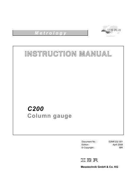
M e t r o l o g y<br />
INSTRUCTION MANUAL<br />
<strong>C200</strong><br />
<strong>Column</strong> gauge<br />
Document No. : D2MF232 001<br />
Edition : April 2008<br />
© Copyright : IBR<br />
Messtechnik GmbH & Co. KG
Instruction <strong>Manual</strong> <strong>C200</strong><br />
Contents<br />
1. Introduction<br />
1.1 General information ............................................................................................................ : 4<br />
1.2 Measuring and display features .......................................................................................... : 4<br />
1.3 Front and rear panel ........................................................................................................... : 5<br />
1.4 Dimensions ......................................................................................................................... : 6<br />
1.5 Hole pattern for interconnection .......................................................................................... : 6<br />
1.6 Technical data .................................................................................................................... : 7<br />
2. Getting started<br />
2.1 Delivered items .................................................................................................................... : 8<br />
2.2 Fitting the base ................................................................................................................... : 8<br />
2.3 Fitting the IMBus modules ................................................................................................... : 8<br />
2.3.1 Removal of <strong>C200</strong> column cover ................................................................................ : 8<br />
2.3.2 Connecting the IMBus modules ................................................................................ : 9<br />
2.3.3 Fitting IMBus modules in <strong>C200</strong> column gauges ........................................................ : 10<br />
2.3.4 Fitting of bus terminator ............................................................................................ : 10<br />
2.3.5 Fitting of <strong>C200</strong> column cover .................................................................................... : 11<br />
2.4 Measurement input addresses ............................................................................................ : 11<br />
2.5 Connecting several column gauges .................................................................................... : 12<br />
2.6 Power supply connection .................................................................................................... : 13<br />
2.7 Connecting a foot or hand switch ........................................................................................ : 14<br />
2.8 Connecting adaptors for tolerance outputs ......................................................................... : 14<br />
2.9 Connecting a PC, multiplexer or statistic printer ................................................................. : 15<br />
2.10 Connection of wireless module ........................................................................................... : 15<br />
2.11 Connection of probes, air plug gauges, sensors and measuring instruments ..................... : 16<br />
2.12 IMBus modules at a glance .................................................................................................: 18<br />
2.13 Power on / Self-test ............................................................................................................. : 18<br />
3. Programming the column gauge<br />
3.1 Encoder functions ............................................................................................................... : 19<br />
3.2 Foot and hand switch functions ...........................................................................................: 19<br />
3.3 Quick programming guide for programmers in a hurry ....................................................... : 20<br />
3.4 Description of calibration mode ........................................................................................... : 21<br />
3.4.1 Zero adjustment / Calibration .................................................................................... : 21<br />
3.4.2 Probe set-up ............................................................................................................. : 21<br />
3.5 Description of programming mode ...................................................................................... : 22<br />
3.6 Basic Settings .................................................................................................................... : 27<br />
3.7 Restoring factory settings .................................................................................................... : 31<br />
3.8 Error messages / Error corrections ..................................................................................... : 31<br />
3.8.1 Operating and programming errors ........................................................................... : 31<br />
3.8.2 System error ............................................................................................................. : 32<br />
4. Working with the column gauge<br />
4.1 Initial start-up ...................................................................................................................... : 33<br />
4.2 Measurement operation ...................................................................................................... : 33<br />
4.3 Mechanical set-up of inductive probes ................................................................................ : 33<br />
4.4 Automatic zero adjustment of gauges ................................................................................. : 34<br />
4.5 Automatic gauge calibration ................................................................................................ : 34<br />
4.6 Multi gauging ( C1...C8 ) ..................................................................................................... : 34<br />
2
Instruction <strong>Manual</strong> <strong>C200</strong><br />
5. The RS232 interface<br />
5.1 Transmissin format and wiring ............................................................................................ : 35<br />
5.2 Data format ......................................................................................................................... : 35<br />
5.3 Table of commands ............................................................................................................ : 35<br />
5.4 Requesting measured values .............................................................................................. : 36<br />
5.5 Transfer of measured data ................................................................................................. : 36<br />
5.6 Importing measurement values into Windows applications ............................................... : 36<br />
5.7 Importing measurement values into MS-EXCEL ................................................................ : 36<br />
6. Male connector pin assignments<br />
6.1 IMB-mc1 measuring controller connectors .......................................................................... : 37<br />
6.2 Termina blocks for accessories ........................................................................................... : 37<br />
7. Accessosries and order placement information ...................................................................... : 39<br />
8. Safety Instructions ..................................................................................................................... : 42<br />
9. Declaration of conformity .......................................................................................................... : 43<br />
10. Guarantee ..................................................................................................................................... : 43<br />
3
Instruction <strong>Manual</strong> <strong>C200</strong><br />
1. Introduction<br />
1.1 General information<br />
The <strong>C200</strong> column gauge is an electronic gauge for connecting<br />
1 to 8 inductive or incremental probes, pneumatic<br />
gauge heads, sensors with analogue current or voltage<br />
outputs and gauges with digital interfaces. The high flexibility<br />
of connecting sensors and gauges is achieved due to<br />
the modular design and the usage of IMBus modules.<br />
The column gauge allows the manual or automatic selection<br />
of 1 to 8 gauges, including static and dynamic measuring<br />
programmes and the optional selection (grading) of<br />
workpieces in up to 30 classes.<br />
Highly sophisticated measuring programmes allow a quick<br />
and simple calibration with 1 or 2 masters.<br />
Two numeric displays allow the output of absolute measured<br />
values, comparative deviations or the classification of<br />
workpieces as well as the corresponding gauge numbers.<br />
The 3-colour column display with superimposable tolerance<br />
limits gives a fast overview over the tolerance result<br />
of the workpieces and is an ideal tool for quality checks of<br />
workpieces in mass production.<br />
The new Bus system of the <strong>C200</strong> provides solutions for<br />
more sophisticated measuring applications through the<br />
simple interconnection of several column gauges.<br />
1.2 Measuring and display features<br />
Static measuring mode<br />
Dynamic measuring modes : Min, Max, Tir, Mean<br />
Bore measuring mode with automatic function<br />
Multi-gauging measuring modes :<br />
<strong>Manual</strong> or automatic selection of 1 to 8 gauges<br />
Measuring range / Resolution : ± 3.0 mm / 0.1 µm, 0.12 / 0.00001 inches ( inductive probes )<br />
± 30 mm / 1 µm, 1.2 / 0.0001 inches ( inductive probes )<br />
24 bit ( incremental measuring systems )<br />
Unit : mm and inches<br />
2-digit numeric display : Gauge number C1 … C8<br />
Measuring input P1 … P8<br />
Basic setup menu L0 … L9<br />
Numeric display ranges<br />
Relative measurements : ± 9.9999 mm / ±99.999 mm, ±.99999 inches / ±9.9999 inches<br />
Absolute measurements : 0 to 99.9999 mm / 0 to 999.999 mm, 0 to 9.99999 inches / 0 to 99.9999<br />
inches<br />
Number of grades : 1…30<br />
4
Instruction <strong>Manual</strong> <strong>C200</strong><br />
<strong>Column</strong> display ranges<br />
± 5.0000 mm ± 0.50000 ″ The 3-colour column display ( red, green, yellow )<br />
± 1.5000 mm ± 0.15000 ″ features an automatic colour selection according<br />
± 0.5000 mm ± 0.05000 ″ to the tolerance limits.<br />
± 0.1500 mm ± 0.01500 ″ A maximum of 4 tolerance limits can be programmed.<br />
± 0.0500 mm ± 0.00500 ″ The tolerance limits are output as coloured marks inside<br />
± 0.0150 mm ± 0.00150 ″ the column display.<br />
± 0.0050 mm ± 0.00050 ″<br />
The column display ranges can be set to AUTO or to a fixed range in the BASIC SETUP menu. In the AUTO mode the<br />
column gauge automatically selects the optimal column display range depending on the given tolerance limits. The selected<br />
column display range is shown in the measuring mode on the numeric display by pressing the Encoder button<br />
for more than 2 seconds. User-defined column display ranges can be programmed with the PC software B<strong>C200</strong>.EXE.<br />
1.3 Front and rear panel<br />
Bus terminator<br />
Tolerance limits (4)<br />
3-colour column<br />
IMB modules for:<br />
Inductive probes<br />
Pneumatic gauge heads<br />
Incremental probes<br />
Analogue currents<br />
Analogue voltages<br />
Numeric display 2-digit<br />
Digital gauges<br />
Dynamic mode display<br />
RS232 connector<br />
Numeric display 6-digit<br />
Foot / Hand switch and<br />
tolerance outputs<br />
Programming menu<br />
Rotary encoder<br />
IMB power supply:<br />
IMB – ps2: 85 to 260 VAC<br />
- optional -<br />
IMB – dc1: 9 to 32 VDC<br />
IMB – acc: Accu pack<br />
5
Instruction <strong>Manual</strong> <strong>C200</strong><br />
1.4 Dimensions<br />
Picture: <strong>Column</strong> display with base<br />
1.5 Hole pattern for interconnection<br />
6
Instruction <strong>Manual</strong> <strong>C200</strong><br />
1.6 Technical data<br />
Mechanical characteristics<br />
Case Aluminium anodised, plastic top and bottom parts<br />
Base Aluminium powder-coated<br />
Front panel Plexiglass<br />
Control element Rotary encoder with button<br />
(16 detents / rotation)<br />
Dimensions W x H x D / Weight 56 x 418.5 x 86 mm / 1340g ( incl. base )<br />
( <strong>C200</strong> incl. base, IMB-ps2 and IMB-mc1 = 1650g )<br />
Electrical characteristics<br />
Power supplies: IMB – ps2<br />
IMB – dc1<br />
IMB – acc<br />
Primary switched power supply 100 to 240VAC, 45 to 60Hz<br />
Power supply with DC voltage input 9 to 32VDC<br />
Accumulator module for portable units<br />
Max. power consumption 2.5 VA ( without measuring modules )<br />
<strong>Column</strong> display<br />
Numeric display<br />
Mode, unit, programming menu LEDs<br />
Scale with 103 and 2 LEDs for “out-of-range” display,<br />
3-colour, with automatic colour selection and<br />
programmable tolerance marks<br />
6-digit and 2-digit LED displays: 7.62 mm, red<br />
17 LEDs, red<br />
Display<br />
Interface (RS232)<br />
2 trigger inputs / tolerance outputs<br />
(Ft 1 / Ft 2)<br />
Connections<br />
9-pin SUB-D port, hardware: EIA RS232 standard,<br />
data format corresponds to OPTO RS232<br />
9-pin SUB-D port<br />
Trigger input for external contacts and serial<br />
output for OC3, OE3 and OP3 adapters<br />
Measurement parameters<br />
Measuring range / Resolution ± 99.9999 mm / 0.1 µm, ± 4.00000 / 0.00001 inches<br />
± 999.999 mm / 1 µm, ± 40.0000 / 0.0001 inches<br />
Resolution 16 bits ( analogue ), 24 bits ( incremental measuring systems )<br />
Sampling rate 50 measurements per second<br />
For measurement error specifications, linearity, hysteresis and temperature drift please refer to the technical data<br />
pertaining to the IMBus measuring module in question<br />
IMBus<br />
(IBR Mess Bus)<br />
Bus<br />
9-pin SUB-D male (input) / female ( output ),<br />
Hardware: EIA RS485 Half Duplex, automatic addressing,<br />
max. of 64 clients, max. Bus length 1200 m<br />
Environmental conditions<br />
Operating temperature range 0 to 50°C<br />
Storage temperature range -30 to +60°C<br />
Protection Front panel IP65 ( CEI / IEC 529 )<br />
Rear panel depending on the IMBus measuring modules<br />
Electromagnetic compatibility ( EMC )<br />
Electromagnetic compatibility (EMC)<br />
Generation of interference according to EN50081-2<br />
Resistance to interference according to EN50082-2<br />
7
Instruction <strong>Manual</strong> <strong>C200</strong><br />
2. Getting started<br />
2.1 Delivered items<br />
<strong>Column</strong> gauge, base with 4 screws ( M3x8 ) for fixing, instruction manual, programming card, and<br />
a 2.0 mm Allen key.<br />
Further accessories, such as IMBus measuring controllers, power supply modules, measurement<br />
modules, foot switches, or adaptors according to shipping order.<br />
Please check the shipment for completeness and keep the packaging.<br />
2.2 Fitting the base<br />
4 DIN 7984 M3 x 8<br />
Use the Allen key ( included in shipment )<br />
to fixate the screws of the base and set<br />
the column gauge on a solid base.<br />
!!! Do not overtighten screws !!!<br />
2.3 Fitting the IMBus modules<br />
The <strong>C200</strong> column gauge has been developed for use in IMBus modules and provides for the connection of<br />
1 to 8 probes, air plug gauges, sensors and digital measuring instruments. The respective modules of the<br />
IMBus series can be fitted to the rear panel of the <strong>C200</strong> to connect probes, sensors and gauges.<br />
See IMBus Module Overview, Chapter 2.12<br />
2 DIN 7984 M3 x 8<br />
2.3.1 Removal of <strong>C200</strong> column cover<br />
Use the Allen key ( included in<br />
shipment ) to undo and remove both<br />
retaining screws of the column cover.<br />
Then remove the column cover.<br />
8
Instruction <strong>Manual</strong> <strong>C200</strong><br />
A <strong>C200</strong> column gauge that comprises IMBus modules is configured in a fixed order. If one single <strong>C200</strong> is to<br />
be configured, the power supply model ( 1 ) always has to be fitted first, followed by the IMB-mc1 measuring<br />
controller module ( 2 ) and then finally ( starting with no. 3 ) the IMBus measuring and interface modules<br />
in no fixed order. The address designation ( Ch.1 to Ch.8 ) of the connected sensors or measuring<br />
instruments determines the order. The <strong>C200</strong> column gauge can read a maximum of 8 connected sensors<br />
or measuring instruments.<br />
If several <strong>C200</strong> are to be connected, the IMB-cas adaptor cable ( 1 ) is to be fitted first, followed by the<br />
power supply module ( 2 ), then the IMB-mc1 measuring controller and finally the IMBus measuring and<br />
interface module in no fixed order.<br />
One power supply module can support up to 3 <strong>C200</strong> column gauges in this way. If more than 3 <strong>C200</strong> are<br />
interconnected, an additional power supply module has to be fitted for the fourth <strong>C200</strong>.<br />
Extensions cables can be used at any point between the individual IMBus modules, if needed. Sensitive<br />
signal leads from inductive probes, for instance, or long pneumatic hoses for pneumatic measurement<br />
configurations can hence be avoided. The total maximum length of all IMBus extension cables must not<br />
exceed 1200 m.<br />
2.3.2 Connecting the IMBus modules<br />
(1) Push both red levers of the first module against the stop and rotate at stop ( set up ).<br />
(2) Connect modules.<br />
(3) Turn over both red levers to lock and press modules together.<br />
(1) (2) (3)<br />
Follow steps (1), (2) and (3) to connect the IMBus modules in series.<br />
The following table indicates the installation sequence for IMBus modules.<br />
Position 1 is the bottommost position later on, and is fixed with screws in the base of the <strong>C200</strong> column<br />
gauge.<br />
!!! Important: The bottommost IMBus module must be equipped with bolts to do so.<br />
Position IMBus module<br />
1 IMB-cas ( only if interconnecting several column gauges )<br />
2 IMB-ps2, or IMB-dc1 as an alternative; IMB-acc (power supply modules )<br />
3 IMB-mc1 ( measuring controllers )<br />
4 IMBus gauging and interface modules<br />
Important :<br />
Should an IMBus module already be equipped with bolts (e.g. IMB-ps2 when using an IMB-cas<br />
adaptor cable), pleased replace the bolts with 2 Phillips head screws SH-UNC / 4-40*9.5.<br />
( included in shipment ) to able to connect the modules.<br />
9
Instruction <strong>Manual</strong> <strong>C200</strong><br />
2.3.3 Fitting IMBus modules in <strong>C200</strong> column gauges<br />
Once the IMBus modules have been connected, they are slid as a package from the top into the<br />
<strong>C200</strong> column section and then fixed with both Phillips head screws to the column base.<br />
!!! Do not overtighten screws !!!<br />
If modules have already been fitted in the <strong>C200</strong> column and additional modules are to be installed,<br />
then all previously fitted modules will have to be removed first.<br />
Undoing and removing previously fitted IMBus modules :<br />
The IMBus modules are fixed with 2 screws to the <strong>C200</strong> base. A Phillips head screwdriver is<br />
needed first to undo both Phillips head screws, so that the modules can be removed. Two lock<br />
washers keep the screws in place and they remain in the <strong>C200</strong> base. The base does not need<br />
to be removed. Once both screws have been completely undone, the IMBus modules can be<br />
slid to the top of the column and removed.<br />
Undo screws<br />
Remove<br />
IMBus modules<br />
After removal of previous modules, additional modules<br />
can be added and fitted as a complete package into<br />
the <strong>C200</strong> and fixed with screws.<br />
2.3.4 Fitting of bus terminator<br />
Once the modules have been fixed with screws to the base, the bus terminating resistor connector<br />
is attached to the vacant port of the last module and secured.<br />
If the last module has not been fitted with bolts to fix the terminating connector, both Phillips head<br />
screws will have to be removed and replaced with bolts.<br />
The bolts are included in the shipment !!!<br />
10
Instruction <strong>Manual</strong> <strong>C200</strong><br />
About the bus terminator :<br />
The purpose of the bus terminator is to terminate the electric bus lines, to seal the open port, and<br />
to provide information on the performance and the power supply of the column gauge.<br />
The “VCC” LED lights up when the power supply to the column gauge is secure. The “VCC” LED<br />
will be extinguished, if the power supply module has been overloaded due to external consumers,<br />
such as digital probes that use a lot of power, or as a result of drops in voltage with long IMBus<br />
extension cables. The IMBus design, however, provides for adding any number of power supply<br />
modules between the IMBus gauging and interface modules to compensate for drops in voltage.<br />
The “RUN” LED lights up, when the self-test for all IMBus modules has finished successfully.<br />
The “RUN” LED will not light up and will thus signal that the bus lines could not be completely<br />
checked, if more IMBus modules have been fitted than can be addressed by the column gauge.<br />
Note : The “RUN” LED will not issue an error message in this instance, but rather the<br />
incomplete self-test of modules that cannot be addressed.<br />
2.3.5 Fitting of <strong>C200</strong> column cover.<br />
Place column cover on top of <strong>C200</strong> and fix<br />
with two Allen screws ( M3 x 8).<br />
!!! Do not overtighten screws !!!<br />
Bus terminating resistor<br />
connector<br />
Ch. 8<br />
Ch. 7<br />
2.4 Measurement input addresses<br />
The measurement inputs are referred to as Ch.1 to Ch.8<br />
for subsequent programming.<br />
The bottommost measurement input is always Ch.1. It<br />
is possible to connect more than 8 measurement inputs,<br />
the <strong>C200</strong> column gauge, however, can only address and<br />
read the first 8 inputs.<br />
Note :<br />
When connecting further column gauges via<br />
IMB-cas adaptor cables, the measurement inputs<br />
of the first gauging column with the same addresses<br />
Ch.1 to Ch.8) are also available for the subsequent<br />
gauging columns. Hence for the purpose of programming<br />
there are no extraordinary items that need to be<br />
observed.<br />
Ch. 6<br />
Ch. 5<br />
Ch. 4<br />
Ch. 3<br />
Ch. 2<br />
Ch. 1<br />
IMB-mc1 measuring<br />
controller module<br />
IMB-ps2 power supply<br />
module<br />
11
Instruction <strong>Manual</strong> <strong>C200</strong><br />
2.5 Connecting several column gauges<br />
IMB-cas type adaptor cables are utilised to connect several column gauges.<br />
The adaptor cables fulfil two tasks :<br />
1.) Transferring the supply voltage from the first column gauge to the next.<br />
One power supply module can support up to 3 column gauges, depending on the connected probes, sensors<br />
and measuring instruments. The number of column gauges decreases, if the connected sensors pick up more<br />
than 200 mA of current. As shown in Example 2, any number of power supply modules can be added. Each<br />
module performs the function of supplying power up to the next power supply module.<br />
2.) The measurement inputs from Ch.1 to Ch.8 of the first column gauge are made available for the subsequent<br />
column gauges.<br />
The measurement input signals are transmitted via the IMB-cas adaptor cables to the subsequent column<br />
gauges. The data flow of the adaptor cable is always routed from the thinner adaptor housing towards the<br />
thicker adaptor housing. A measuring module in a series of column gauges will interrupt the connection to<br />
the previous measuring modules, and make available its own inputs for the subsequent column gauges.<br />
Mechanical connection of column gauges :<br />
The housing connector underneath the IMBus column<br />
cover serves to link together the column gauges. Remove<br />
the connector from its deposit and fix it with<br />
screws to the column cover.<br />
!!! Do not overtighten screws !!!<br />
1. Example with 3 column gauges<br />
The three-column gauges are linked together via two<br />
IMB-cas adaptor cables. The adaptor cables are<br />
always plugged in the first position ( bottommost slot ),<br />
whereby the thinner adaptor section is always connected<br />
to the first column gauge.<br />
The power supply module for the first column gauge<br />
supplies the third column gauge with power. The<br />
measurement inputs Ch.1 to Ch.8 are available at<br />
all three column gauges.<br />
12
Instruction <strong>Manual</strong><br />
<strong>C200</strong><br />
2. Example with 5 column gauges<br />
The five column gauges are linked together via<br />
four IMB-cas adaptor cables. The cables are<br />
always connected to the bottommost slots, as<br />
shown in the diagram. The measurement input<br />
signals are transmitted from the thinner adaptor<br />
section towards the thicker adaptor section.<br />
The power supply module for column 1<br />
supplies columns 1, 2 and 3 with power. The<br />
power supply module for column 4 automatically<br />
interrupts the further power supply to<br />
column 1 and supplies columns 4 and 5 with<br />
power. The measuring module in column 1<br />
makes available the measurement inputs for<br />
Ch.1 to Ch.4 for columns 1 and 2. The measuring<br />
module in column 3 automatically interrupts<br />
the connection to the measurement inputs<br />
from column 1 and makes available its<br />
own measurement inputs for columns 3, 4<br />
and 5.<br />
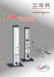
2.6 Power supply connection<br />
There are three modules available from the IMBus series to supply the column gauge with power:<br />
1. IMB-ps2: ( Part No. F121 020 )<br />
Switched-mode power supply (SMPS) with broad voltage range<br />
from 100 to 240 VAC, 45 to 60 Hz<br />
2. IMB-dc1: ( Part No. F121 040 )<br />
DC to DC converter for input voltage range from 9 to 32 VDC<br />
3. IMB-acc: ( Part No. F121 030 )<br />
Rechargeable battery (accu-pack) module for battery-operated service.<br />
The module facilitates fast battery replacement. Rechargeable batteries<br />
of 1850 / 4000 to 5500 mAh are available.<br />
( Example: <strong>C200</strong> with 2 inductive probes and a 4000 mAh battery pack<br />
can operate for approx. 12 to 15 hours )<br />
First read the sticker information on the fitted power<br />
supply module and then check whether the module is<br />
compatible with your mains and/or direct voltage.<br />
Use the attached power cable to connect the IMB-ps2.<br />
Important !!!<br />
Insert device plug into grounded<br />
outlet only<br />
13
Instruction <strong>Manual</strong><br />
<strong>C200</strong><br />
2.7 Connecting a foot or hand switch<br />
The foot or hand switches are connected to the IMB-mc1 measuring controller to the Sub-D ports Ft1<br />
and Ft2.<br />
A third switch input is available, if an IMB foot or hand switch is used. The IMB foot or hand switch can<br />
be added any place upstream of the IMB-mc1.<br />
The functions of the foot or hand switch can be configured in the “BASIC SETTINGS”<br />
menu ( L3 -L5 ).<br />
Types of foot or hand switches : Part No.<br />
Foot switch IP32.................................... F121 110<br />
Foot switch IP65 ................................... F121 120<br />
IMBus foot switch IP32 ......................... F121 130<br />
IMBus foot switch IP65 ......................... F121 140<br />
IMB-Ft<br />
RS232<br />
Ft2<br />
Ft1<br />
Hand switch IP65 .................................. F121 150<br />
IMBus hand switch IP65 ....................... F121 160<br />
Important !!!<br />
Fix all plug-in connections with screws to<br />
ensure secure fit.<br />
Plug-in connector pin assignments :<br />
see Chapter 6<br />
2.8 Connecting adaptors for tolerance outputs<br />
The adaptors for the actuator outputs for the<br />
tolerances are connected at the rear of the<br />
column gauge to the Ft1 or Ft2 Sub-D ports<br />
of the IMB-mc1 measuring controller.<br />
A total of 5 actuator outputs are available:<br />
1. Upper tolerance limit ( red ) exceeded<br />
2. Upper contact limit ( yellow ) exceeded<br />
3. Measured value OK<br />
4. Below lower contact limit ( yellow )<br />
5. Below lower tolerance limit ( red )<br />
Types of connection adaptors: Part No.<br />
Open collector adaptor OC3 ........... F603 001<br />
Open emitter adaptor OE3 ........... F603 002<br />
Optocoupler adaptor OP3 ........... F603 003<br />
Ft2<br />
Ft1<br />
Adaptor pin assignment, OC3 / OE3 / OP3<br />
see Chapter 6; for more information on adaptors<br />
see Data Sheets, Doc. D1F603 001, D1F603 002, D1F603 003.<br />
14
Instruction <strong>Manual</strong><br />
<strong>C200</strong><br />
2.9 Connecting a PC, multiplexer or statistic printer<br />
A PC ( COM 1… 8, USB ), a multiplexer or a statistic printer can be connected at the rear panel of the<br />
column gauge of the IMB-mc1 measuring controller via the RS232 Sub-D port.<br />
RS232 PC cable<br />
USB PC cable<br />
RSD adaptor (Mitutoyo Digimatic)<br />
RS232<br />
RSA adaptor ( analogue output of measured values, ± 10V )<br />
See Chapter 6 for RS232 pin assignment !!!<br />
Select connection cable or adaptor according to<br />
.. . the PC, multiplexer, statistic printer, or other<br />
recording device interface.<br />
RS232 PC cable RS232 connection cable for PC COM1 to COM8 interfaces ................................. F601 002<br />
USB PC cable USB connection cable for PCs incl. driver software for emulation of .................... F601 020<br />
COM1…127 interfaces<br />
RSD adaptor connection cable with interface converter to Mitutoyo Digimatic output ............... F601 030<br />
( cable converts RS232 output to DIGIMATIC output )<br />
RSA adaptor adaptor with digital / analogue converter to output analogue ............................... F601 031<br />
voltages to terminal block<br />
( adaptor converts RS232 output to ±10V analogue output )<br />
2.10 Connection of wireless module<br />
RS232<br />
The wireless IBRit-rf1-232 module is connected<br />
at the rear<br />
of the column gauge to the RS232 port. The<br />
wireless module enables the wireless transmission<br />
of measured values to the PCs.<br />
For more information go to : www.IBRit.com<br />
( IBRit-rf1 series )<br />
IBRit-rf1-232 Wireless module for stationary gauges ..... F604 008<br />
with RS232 output<br />
15
Instruction <strong>Manual</strong><br />
<strong>C200</strong><br />
2.11 Connection of probes, air plug gauges, sensors and measuring instruments<br />
The modular design in conjunction with the IMBus measuring and interface modules provides for connecting<br />
virtually any probe, pneumatic gauge head, sensor or measuring instrument to the column gauge.<br />
A maximum of 8 measurement input can be queried with the <strong>C200</strong>. It is possible to connect more than<br />
8 inputs, however, the additional inputs are not taken into account. The RUN LED on the bus terminating<br />
resistor connector does not light up, unless all surplus IMBus modules can be completely addressed ( see<br />
page 11, Information on Bus Terminator ). The IMBus measuring and interface modules can be combined in<br />
any order and provide for the connection of different types of sensors ( inductive, digital, pneumatic, etc. ).<br />
For an overview of IMBus measuring and interface modules see Chapter 2.12<br />
1. example : Connection of inductive probes<br />
Prior to connecting the probes, check whether the<br />
types of probes concur with the type designations<br />
listed on the IMBus module ( IMB-im1 / 2 / 4 / 8 ).<br />
Secure the connectors by screwing them tight.<br />
Important !!!<br />
Reliable measurements can only be guaranteed,<br />
if the connections have been screwed tight,<br />
so that the contact to the probe shield is good.<br />
2. example : IMBus measuring and interface module extensions<br />
IMBus extension cables can be utilised to perfectly<br />
adapt measurement configurations with IMBus modules<br />
to spatial requirements. The extension cables can be used<br />
to interconnect all modules and achieve a maximum length<br />
of 1200 m.<br />
Use genuine IMBus extension cables and bus ports only !!!<br />
Note :<br />
The IMBus is based on an RS485 interface and has been<br />
designed for the demands of industrial use.<br />
Bus terminator<br />
16
Instruction <strong>Manual</strong><br />
<strong>C200</strong><br />
3. example : Connection of pneumatic gauge heads<br />
The column gauge provides for the connection<br />
of 8 pneumatic IMB-ae1 transformers<br />
at the most. An 8-by-6 mm hose<br />
( 8 mm -> outer diameter; 6 mm -> inner<br />
diameter ) is used to connect to the compressed<br />
air supply.<br />
Use dry, oil-free and filtered ( 5 µm ) compressed<br />
air only ranging from<br />
2 - 3 bars ( 2000 to 3000 HPA / 20…45<br />
psi ) to connect to the IMB-ae1 transformers.<br />
Oil and pollutants can destroy<br />
the measurement system !!!<br />
For more information see IMB-ae1 <strong>Manual</strong>, Doc. D1MF122 081<br />
4. example : Connection of different sensors<br />
The example depicts the <strong>C200</strong><br />
configuration for connecting<br />
2 inductive probes ( IMB-im2 ),<br />
2 incremental probes with<br />
1Vss output ( IMB-dm2 ), a<br />
pneumatic plug gauge ( IMB-ae1 ),<br />
2 Mitutoyo dial gauges ( IMB-mi2 )<br />
and a calliper gauge ( Sylvac, Tesa,<br />
Mahr, etc. ) with RS232 Opto output<br />
( IMB-sm1 ).<br />
17
Instruction <strong>Manual</strong><br />
<strong>C200</strong><br />
2.12 IMBus modules at a glance<br />
The modules shown below provide an overview of IMBus measuring and interface modules that can be<br />
connected to the <strong>C200</strong> column gauge.<br />
!!! For more information see IMBus series !!!<br />
2.13 Power on / Self-test<br />
Every time the column gauge is switched on, a self-test will run automatically to check all system components.<br />
If an error is detected during a self-test, the numeric display will indicate an error message.<br />
If the display remains dark, after the <strong>C200</strong> column gauge was switched on, check both, the VCC and<br />
RUN LEDs on the bus terminating resistor connector.<br />
Both LEDs must be lit !!!<br />
VCC - LED is lit when power supply is available<br />
RUN - LED is lit when the internal self-test for all modules has finished successfully.<br />
See Chapter 2.3.4 for more information<br />
A gauge test routine runs subsequently, during which all gauge elements are switched on in series,<br />
enabling the user to check the operation of the gauge. Once the column test has been completed, information<br />
on the release of the software is shown on the six-digit numeric display.<br />
The RS232 interface of the column gauge is not active when the self-test is running.<br />
18
Instruction <strong>Manual</strong><br />
<strong>C200</strong><br />
3. Programming the column gauge<br />
The rotary pulse encoder on the front panel is used to make all settings and complete any programming.<br />
The user is guided through the individual menus, step by step, and prompted by the LED and numeric<br />
displays. The programming procedure follows a logic structure and becomes self-explanatory after studying<br />
it briefly.<br />
Abbreviations used :<br />
Encoder : Rotary pulse encoder with buttons<br />
CW : Turn encoder clockwise<br />
CCW : Turn encoder counterclockwise<br />
3.1 Encoder functions<br />
Turning the encoder By turning the encoder clockwise ( CW ) in the Measuring Mode, you can switch<br />
to the Calibration Mode or the Programming Mode.<br />
In the Calibration or Programming Mode, the flashing value or function can be<br />
changed by turning the encoder.<br />
CW - increases the value or moves to the next function<br />
CCW - reduces the value or returns to previous function<br />
Pushing the encoder By pushing the encoder button in the Measuring Mode, the function selected<br />
under Basic Settings is executed.<br />
Programming is carried out in “BASIC SETTINGS” menu, under Section “L2” - Function<br />
of encoder button in measuring mode<br />
Press the encoder button in the Calibration or Programming Mode to accept<br />
the programmed value or the flashing setting respectively.<br />
Press and hold<br />
for > 2 sec-<br />
The six-digit numeric display indicates the column gauge range in the Measuring<br />
Mode.<br />
The programmed value ( e.g. nominal measure ) of the corresponding, flashing<br />
menu LED is displayed for 1 second in the Programming Mode.<br />
Pushing and Turning Switches to and from the activated measurement points C1…C8 in the Measuring<br />
Mode.<br />
The measurement points ( C1…C8 ) are activated in the “BASIC SETTINGS”<br />
menu, under Section “L0” - Activate / Deactivate measurement points<br />
3.2 Foot and hand switch functions<br />
The column gauge provides for the connection of 3 foot or hand switches. The function for the individual<br />
buttons can be assigned in the “BASIC SETTINGS” menu, under Sections L3 to L5.<br />
19
Instruction <strong>Manual</strong><br />
<strong>C200</strong><br />
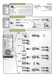
3.3 Quick programming guide for programmers in a hurry<br />
Menu selection and programming<br />
1. Turn the encoder clockwise ( CW ) to change to the programming mode<br />
Turn the encoder counterclockwise ( CCW ) to exit the programming mode<br />
2. The respective gauge element that can be changed flashes in the programming mode.<br />
3. Turn the encoder to change the flashing gauge element. ( CW -> +1 or to go to the next function;<br />
CCW -> -1 or to go to the previous function ).<br />
4. Press the encoder button to accept or confirm a flashing setting<br />
Menu overview<br />
Entry of<br />
Calibration mode<br />
Unit / Pitch<br />
<br />
<br />
Entry or selection<br />
Perform zero adjustment or calibration<br />
Menu for mechanical adjustment of probes<br />
mm (0.0001 / 0.001 ) / inches ( 0.00001 / 0.0001 )<br />
Programming of column gauge<br />
Nominal size<br />
Tolerances<br />
<br />
<br />
Zero point of column gauge<br />
Tolerance limit 1 to 4 as deviation from nominal size<br />
Measurement inputs<br />
Measuring mode<br />
Master value<br />
<br />
<br />
<br />
Coefficients and linking of measurement inputs Ch.1 to Ch.8<br />
Static measurement<br />
Dynamic measurement ( min, max, TIR, mean, bore )<br />
Calibration value for zero calibration<br />
Calibration values for measurement point calibration<br />
Basic setting<br />
L0. - Activate / Deactivate measurement points<br />
L1. - Automatic measurement point changeover ( on / oFF )<br />
L2. - Function of encoder button in measuring mode<br />
L3. - Function of foot / hand switch Ft1 in measuring mode<br />
L4. - Function of foot / hand switch Ft2 in measuring mode<br />
L5. - Function of IMB foot / hand switch in measuring mode<br />
L6. - RS232 output control<br />
L7. - Basic setting of column gauge ( column starting point, column range )<br />
L8. - Setting the selection mode<br />
L9. - Setting password protection<br />
For quick help during programming use the programming reference card !!!<br />
The card provides useful information and is a valuable source of information for everyday work with<br />
the column gauge.<br />
First-time users of the column gauge should carefully read the instructions given in the following<br />
chapter which provides detailed information on the individual programming steps.<br />
Users with basic knowledge of the column gauge should turn to the next chapter for reference.<br />
20
Instruction <strong>Manual</strong><br />
<strong>C200</strong><br />
3.4 Description of calibration mode<br />
Turn the encoder clockwise (CW) and then push the encoder to select the CALIBRATION menu.<br />
Two functions are available in the calibration mode:<br />
1. Zero adjustment with a master or calibration with two masters ( CAL.1, CAL.2 flash )<br />
2. Probe set-up ( AdJuSt flashes )<br />
3. Exit menu ( rEturn flashes )<br />
Turn the encoder to select the required function and then push the encoder button to access the function.<br />
3.4.1 Zero adjustment / Calibration :<br />
If the CALIBRATION menu has been selected, the display will alternately change from CAL. 1 to the<br />
current value measured. Place a master or one of the masters in the measuring instrument. Push the<br />
encoder button to start the automatic Zero adjustment or the Measurement point calibration.<br />
Zero adjustment (only one master was entered in the MASTER VALUE menu):<br />
The master value is adopted as measurement value by the gauge, and the column gauge returns to<br />
the measuring mode.<br />
Measurement point calibration ( two masters were entered in the MASTER VALUE menu ) :<br />
At the start of the automatic measurement point calibration, the first master value was measured,<br />
and the numeric display indicates alternately CAL. 2 and the measured value.<br />
Insert the second master now and confirm by pushing the encoder button.<br />
The column gauge then computes the new offset value and the amplification.<br />
The second master value is then adopted as measurement value by the gauge and the column<br />
gauge returns to the measuring mode.<br />
3.4.2 Probe set-up<br />
Inductive probes achieve their greatest degree of accuracy within a comparatively small measurement<br />
range only. It is therefore extremely important to carefully set up the probes at the electric zero point.<br />
On selection of the AdJuSt menu, the two-digit numeric display shows the measurement input P1 and<br />
the six-digit numeric display indicates the “raw value” of the probe from measurement input 1. The column<br />
gauge tolerance limits have automatically been set to 50µm. The first inductive probe can now be set up.<br />
Insert a workpiece or a master to do so. Adjust the probe in the holding fixture until the column gauge<br />
turns green.<br />
Turn the encoder to activate all measurement inputs ( P1…P8 ) in series and to set up all inductive<br />
probes. Push the encoder button to exit the set-up menu. The column gauge returns to the measuring<br />
mode.<br />
21
Instruction <strong>Manual</strong><br />
<strong>C200</strong><br />
3.5 Description of programming mode<br />
Turn the encoder clockwise ( CW ) to change from the Measuring Mode to the Programming Mode.<br />
- The six-digit numeric display indicates ‘ProGr.’.<br />
Programming menus :<br />
You can select the first menu ( UNIT / PITCH - LED flashes ) by pushing the encoder button. You can select<br />
the Unit of Measurement and the Pitch ( measuring pitch ) in the menu. Turn the encoder to select the<br />
unit of measurement, either “mm” or “INCH” and then confirm by pushing the encoder button.<br />
Turn the encoder to select the pitch and confirm by pushing the encoder button.<br />
The UNIT / PITCH Led is flashing again now.<br />
Turn the encoder :<br />
CW - to go to the NOMINAL SIZE menu item<br />
CCW - to return to the measuring mode MEASURE<br />
Note :<br />
When changing the unit or the pitch, the programmed numeric values, such as master values, nominal<br />
sizes, or tolerances are not automatically changed by the column gauge.<br />
22
Instruction <strong>Manual</strong><br />
<strong>C200</strong><br />
Turn the encoder button to select the desired number of the<br />
flashing point and then confirm by pushing the encoder button.<br />
The nominal value determines the value at which the zero point (no deviation) is indicated on the column<br />
gauge. If the nominal value for a workpiece is 20 mm, the column will indicate a deviation of 0.1 mm with<br />
a workpiece of 20.1 mm.<br />
If you just want to check and not change the nominal size, turn the encoder to select the NOMINAL SIZE<br />
menu ( LED flashes ) and then press and hold the encoder for more than 2 seconds. The display will briefly<br />
indicate the nominal size without starting the menu.<br />
Note :<br />
The nominal value is used for zero positioning of the column gauge only and<br />
does not influence the numeric display.<br />
In this menu you can program up to 4 tolerance limits to indicate the relative deviation from the nominal<br />
value.<br />
The first step in programming involves the selection of a tolerance point. The column gauge displays a<br />
selection 4 tolerance points:<br />
+ red - upper tolerance limit<br />
+ yellow - upper action limit<br />
– yellow - lower action limit<br />
– red - lower tolerance limit<br />
The corresponding, active tolerance point flashes. Turn the encoder to change from one tolerance point<br />
to another.The numeric display will indicate the respective state ( OFF ) or the tolerance value set for the<br />
flashing tolerance point.<br />
Push the encoder button to start the programming procedure for the respective tolerance point.<br />
Switch the tolerance point ON or OFF via on/oFF on the numeric display. If the tolerance point has been<br />
activated, the relative deviation to the nominal value ( max. ± 5.9999 mm ) can now be entered.<br />
Note :<br />
If you would like to just check and not change the programmed tolerance value of the flashing tolerance<br />
point, press and hold the encoder button for more than 2 seconds.<br />
The display will briefly indicate the saved value without starting the menu.<br />
23
Instruction <strong>Manual</strong><br />
<strong>C200</strong><br />
The MEASUREMENT INPUTS menu provides for assigning the current measurement point from C1…C8<br />
to the measurement inputs from Ch.1…Ch.8.<br />
The 8 inputs can be linked in any order ( e.g.: Ch.1+Ch.2, Ch.1-Ch.2, Ch.1+Ch.2 - Ch.3+Ch.4, etc. )<br />
Every measurement input can be multiplied by a “fixture coefficient” ( multiplier ) ranging from 0.001 to<br />
59.999. Enter 1 as the multiplying factor, if the input is to be added without correction; enter -1, if the<br />
input is to be subtracted.<br />
Examples :<br />
a) Bore gauge : Ø d1 = - Ch.1<br />
Ch.1 -1.000<br />
Ch.2 off<br />
Ch.3 off<br />
Ch.4 off<br />
Ch.5 off<br />
Ch.6 off<br />
Ch.7 off<br />
Ch.8 off<br />
b) Axial measurement : Ø d1 = Ch.1 + Ch.2<br />
Ch.1 1.000<br />
Ch.2 1.000<br />
Ch.3 off<br />
Ch.4 off<br />
Ch.5 off<br />
Ch.6 off<br />
Ch.7 off<br />
Ch.8 off<br />
c) Taper measurement : Taper = Ø d2 – Ø d1<br />
Taper = ( Ch.3 + Ch.4 ) - ( Ch.1 + Ch.2 )<br />
Taper = Ch.3 + Ch.4 - Ch.1 - Ch.2<br />
Ch.1 - 1.000<br />
Ch.2 - 1.000<br />
Ch.3 1.000<br />
Ch.4 1.000<br />
Ch.5 off<br />
Ch.6 off<br />
Ch.7 off<br />
Ch.8 off<br />
24
Instruction <strong>Manual</strong><br />
<strong>C200</strong><br />
d) Angle measurement : Angle =<br />
Ch.1 - Ch.2 _ Ch.3 - CH.4<br />
2 2<br />
Angle = 0.5 · Ch.1 – 0.5 · Ch.2 – 0.5 · Ch.3 + 0.5 · Ch.4<br />
Ch.1 0.5<br />
Ch.2 - 0.5<br />
Ch.3 - 0.5<br />
Ch.4 0.,5<br />
Ch.5 off<br />
Ch.6 off<br />
Ch.7 off<br />
Ch.8 off<br />
Note :<br />
If all measurement inputs are switched OFF, the numeric display of the column gauge will<br />
indicate ‘Err. 01’ because it is not possible to take a measurement.<br />
If the same measurement input is applied for several measurement points in the operating<br />
mode Automatic Changeover of Measurement Points, the numeric display of the column<br />
gauge will indicate ‘Err. 08’.<br />
If a measurement value were changed for a measurement input that is applied several times,<br />
the measurement values for several measurement points would change at the same time, and<br />
an automatic selection of a measurement point would consequently not be possible.<br />
In addition to the static measuring mode, the <strong>C200</strong> column gauge also has several dynamic measuring<br />
modes available. Each of the 8 measurement points from C1…C8 can be assigned its own measuring<br />
mode.<br />
Turn the encoder to select the MEASURING MODE, then press the encoder to select the menu.<br />
In the display “StAtic” will flash.Turn the encoder to change from the static to the dynamic measuring<br />
mode ( flashing display: “dyn” ) and vice versa.<br />
On selecting the required measuring mode ( static / dynamic ), press the encoder to confirm the mode.<br />
In the dynamic measuring mode, you can turn the encoder to select the mode, after the measurement<br />
was taken. Then press the encoder to confirm the mode selected.<br />
Min Minimum<br />
Max Maximum<br />
TIR Max - Min<br />
Mean ( Max + Min ) / 2<br />
Bore Special bore mode. Zero adjustment is performed in this mode by<br />
applying the most recent dynamic measurement result<br />
25
Instruction <strong>Manual</strong><br />
<strong>C200</strong><br />
Turn the encoder button to select the desired number of the flashing point and then confirm by pushing<br />
the encoder button.<br />
- The first master value has been programmed.<br />
The numeric display now flashes and indicates “2nd on” or “2nd off”. Turn the encoder button to select<br />
whether a zero adjustment is to be performed ( requires one master only, “2nd off” ), or whether the calibration<br />
of measurement points with two masters, “2nd on”, is to be programmed. With “2nd on”, the second<br />
master will then have to be entered.<br />
Note :<br />
The automatic zero adjustment prerequisites the previous entry of a master (standard measure).<br />
For automatic zero adjustment, (select calibration mode; place master in fixture and confirm Cal. 1 by pressing the<br />
encoder button) the gauge adopts the master value as the standard measure.<br />
The master value is programmed at zero if comparative measurements are to be taken (indicates the deviation<br />
from the nominal value). In this case, the master value should equal the nominal value.<br />
The measurements points can be calibrated automatically with pneumatic sensors as an option to the<br />
automatic zero adjustment function. Two masters will have to be programmed to do so. If the same value<br />
has been programmed for both masters, the numeric display will briefly indicate ‘Error’ and the menu of<br />
the second master is started again automatically.<br />
Note :<br />
An offset value is used to set the zero position of the measurement point in reference to the<br />
master for the automatic Zero Adjustment.<br />
For automatic Gauge Calibration, not only the offset value (zero position) is set, but the<br />
gain (pneumatic spread is also adapted automatically.<br />
26
Instruction <strong>Manual</strong><br />
<strong>C200</strong><br />
3.6 Basic settings<br />
The Basic Settings menu comprises all device settings which are usually only programmed for the initial<br />
start-up.<br />
The factory basic setting is identified by an ∗ in the individual menus..<br />
GAGES<br />
Push the encoder button to select the menu. Turn the encoder to browse through the individual<br />
measurement points from C1…C8. The numeric display will indicate the number of the<br />
measurement point and its current status ( on / oFF ).<br />
To change the status of a measurement point, press the encoder button and then turn the encoder<br />
to select the new status. Press again to confirm the new status.<br />
Note :<br />
If all measurement points have been switched OFF ( oFF ), the measurement<br />
point C1 is automatically switched on again when exiting the programming menu<br />
because the measuring mode cannot operate without an active measurement<br />
point.<br />
Auto.rE.<br />
In this menu you can select <strong>Manual</strong> Gauge Recognition or Automatic Gauge Recognition.<br />
Press the encoder button to select the menu. The numeric display indicates Aut.oFF / on.<br />
Turn the encoder to activate ( on ) or deactivate ( oFF ) the automatic gauge recognition<br />
function. Press to confirm the new status.<br />
27
Instruction <strong>Manual</strong><br />
<strong>C200</strong><br />
In the Basic Settings menus L2…L5 the <strong>C200</strong> controller is set via the encoder button and the foot and<br />
hand switch connections Ft1, Ft2 and IMB-Ft1. The encoder button and each one of the 3 foot or hand<br />
switch connections can be assigned a function from the list.<br />
Description of the different functions :<br />
oFF * - No function assigned to the encoder button or the respective foot or hand switch.<br />
GAGESL. -<br />
If this function has been assigned to a particular button or switch, and if that button or switch<br />
is then activated in the measuring mode, you will automatically go to the next activated<br />
measurement point from C1…C8.<br />
CALibr. - If this function has been assigned to a particular button or switch, and if that button or switch<br />
is then activated in the measuring mode, an automatic zero adjustment or an automatic<br />
gauge calibration of the active measurement points from C1…C8 will be performed.<br />
dyn.con.<br />
dYn.diS. -<br />
- If this function has been assigned to a particular button or switch, and if that button or switch<br />
is then activated in the measuring mode, the dynamic measurement function can be con<br />
trolled.<br />
There are two control options :<br />
EdGe : 1. Actuation starts the dynamic measurement function<br />
2. Actuation stops the dynamic measurement function<br />
StAtE : The dynamic measurement function runs for as long as the button is pressed.<br />
If this function has been assigned to a particular button or switch, and if that button or<br />
switch is activated in the measuring mode, you will change over to the dynamic mode<br />
( Min, Max, TIR, etc. ) with display of measured value. The current measurement point,<br />
however, must have been programmed for a dynamic measurement mode. This function<br />
provides for viewing the four results for the Min., Max., TIR, and Mean Value of the workpiece<br />
after the dynamic measurements have been taken.<br />
28
Instruction <strong>Manual</strong><br />
<strong>C200</strong><br />
trAnS - The activation of the trAnS mode freeze-frames the numeric and column display of the<br />
<strong>C200</strong> column. Every time a programmed input ( Ft1, Ft2, IMB-Ft ) is actuated, the current<br />
measured value will be displayed.<br />
hold - The activation of the hold mode effects that the display is freeze-framed for the duration of<br />
the programmed input ( Ft1, Ft2, IMB-Ft ).<br />
rS 232 - The measured value output for the serial interface of the column gauge is programmed in<br />
these menus.<br />
Note :<br />
A dual function assignment for the foot or hand switch inputs Ft1, Ft2 and IMB-Ft is<br />
possible.<br />
Examples of dual function assignments :<br />
1.) Ft1 - Initiates the transfer of data on the RS232 interface and then changes to the<br />
next measurement point from C1…C8.<br />
2.) Ft1 - Initiates the taking of a dynamic measurement. With the second actuation, the<br />
measurement is completed and the result is sent to the RS232..<br />
Note :<br />
Button = Encoder button<br />
Foot. 1 = Foot or hand switch input Ft1<br />
Foot. 2 = Foot or hand switch input Ft2<br />
Foot. 3 = Foot or hand switch input IMB-Ft<br />
Col.diS<br />
- The column gauge range and the starting point of the column gauge is set in this menu.<br />
rAnGE - mm Auto* / 0.0050 / 0.0150 / 0.0500 / 0.1500 / 0.5000 / 1.5000 / 5.0000<br />
inches Auto* / 0.00050 / 0.00150 / 0.00500 / 0.01500 / 0.05000 / 0.15000 /<br />
0.50000<br />
Note : In the Auto mode the column gauge automatically selects the<br />
column gauge range according to the tolerance limits specified.<br />
StArtP. - CentEr <strong>Column</strong> starts at the centre and moves to the top or to the bottom<br />
toP <strong>Column</strong> moves from the top to the bottom<br />
bott. <strong>Column</strong> moves from the bottom to the top<br />
29
Instruction <strong>Manual</strong><br />
<strong>C200</strong><br />
GrAdE<br />
The selection mode can be activated or deactivated independently for each measurement<br />
point from C1…C8 in this menu. The number of selection groups can be set for any number<br />
from 1…30. The number of selection groups determines in how many, equal fields ( linear<br />
pitch ) the tolerance range is split.<br />
Note : If tolerance limits have not been specified, the numeric display in the measuring<br />
mode indicates “ ------ ”<br />
PASS.Cd. For the protection of calibration and/or programming data, password protection<br />
can be activated in this menu.<br />
The numeric display will prompt the assignment of a six-digit password<br />
for password protection of calibration or programming data.<br />
Note : If the calibration menu or the programming menu is selected later,<br />
the column gauge prompts the entry of the six-digit password.<br />
( If you cannot remember the passwords, use the master password 200879<br />
to access the required menu. )<br />
30
Instruction <strong>Manual</strong><br />
<strong>C200</strong><br />
3.7 Restoring factory settings<br />
In order to reset the column gauge to the factory settings, press and hold the encoder button for approx.<br />
5 seconds on the menu item BASIC SETTINGS ( BASIC SETTINGS LED flashes ) until the numeric<br />
display flashes and indicates “rSt oFF”.<br />
1. Turn the encoder to select “rSt. on”.<br />
2. If the encoder is actuated with “rSt. on”, resetting is confirmed and executed.<br />
3. If the encoder button is pressed with “rSt. oFF”, resetting is cancelled.<br />
3.8 Error messages / Error corrections<br />
The numeric display indicates Operating and Programming Errors made by the user and System<br />
Errors of the column gauge.<br />
3.8.1 Operating and programming errors<br />
Err. xx : error message ( Err ), error number ( xx )<br />
Error Error description Error correction<br />
Err. 1 All measurement inputs are switched off in the<br />
probe interconnection or one of the<br />
measurement inputs is defective.<br />
1. Select MEASUREMENT INPUTS and check to<br />
make sure<br />
that at least one measurement input has been<br />
activated.<br />
2. Select CALIBRATE and then AdJuSt and<br />
check the individual measurement inputs.<br />
Err. 2 The wrong password was entered. Enter the correct password.<br />
( If you cannot remember the password, you can use the<br />
default password 200879. )<br />
Err. 8 Automatic gauge recognition<br />
is activated.One measurement input has been<br />
assigned to several measurement points.<br />
The automatic gauge recognition of an active<br />
measurement point is not possible<br />
because this input also changes the measured<br />
values of various measurement points.<br />
Err. 10 For automatic gauge calibration, the same<br />
master was inserted twice.<br />
Err. 11 The discrepancy between the two masters is<br />
too great. ( discrepancy >6.5 mm )<br />
Err. 12 The discrepancy between the two<br />
programmed masters is too great.<br />
( discrepancy >6.5 mm )<br />
Err. 13 Error in automatic gauge calibration.<br />
Err. 14<br />
The calibration factor is too small.<br />
Error during Gauge calibration.<br />
The calibration factor is too high.<br />
There are two ways to eliminate the error:<br />
1. Select BASIC SETTINGS – L1 menu and set<br />
Aut.oFF.<br />
2. Select MEASUREMENT INPUTS and<br />
deactivate the input that was assigned twice.<br />
Repeat the calibration procedure using two<br />
different masters.<br />
Repeat the calibration procedure using two<br />
masters that are not that different.<br />
Select MASTER VALUE and reprogram the<br />
master values.<br />
The difference between the programmed master<br />
values is much greater than the difference<br />
between the measured master values.<br />
Repeat the calibration procedure and check the<br />
master values programmed in the MASTER<br />
VALUE menu.<br />
The difference between the programmed masters<br />
is much smaller than the difference between the<br />
measured master values.<br />
Recalibrate and check the programmed masters<br />
values. Press 'PRG/CAL' key to enter the Programming<br />
mode and check in the menu "Set<br />
Master value(s)" the values.<br />
31
Instruction <strong>Manual</strong><br />
<strong>C200</strong><br />
3.8.1 System errors<br />
System errors are displayed in the event of hardware problems. These error messages assist<br />
our service department in identifying the problem. Switch off the device and then switch it on<br />
again. If the error message recurs, please contact the IBR Service Department.<br />
Error Error description Error correction<br />
<strong>C200</strong> does not receive measurement data. 1. Check IMBus modules.<br />
no.dAtA Causes:<br />
2. Turn on all <strong>C200</strong>s for cascading.<br />
1. IMBus modules have not been connected,<br />
or an IMBus module is defective.<br />
Err. 97<br />
Err. 98<br />
Err. 99<br />
2. Cascading is not possible because the<br />
<strong>C200</strong> with the IMBus measuring and interface<br />
modules is still turned off.<br />
The bootloader version of a connected IMBus<br />
module is < 1.2.<br />
The firmware version of a connected IMBus<br />
module is < 1.6.<br />
Settings were not saved correctly.<br />
Cannot correct error. The IMBus module is not<br />
compatible with the <strong>C200</strong>.<br />
Load IMBus module with new firmware.<br />
Repeat previous step.<br />
32
Instruction <strong>Manual</strong><br />
<strong>C200</strong><br />
4. Working with the column gauge<br />
4.1 Initial start-up<br />
Start by fitting the base and connecting the accessories (inductive probes, foot switches, etc.).<br />
Follow the instructions given in chapter 2 of this manual.<br />
Then program the column gauge for your application. Follow the instructions given in chapter 3 of<br />
this manual.<br />
Use the manual or the programming card to proceed and make all settings.<br />
Now use the master to mechanically set-up the probes in the measurement fixture.<br />
see Chapter 4.3<br />
<strong>Column</strong> gauge calibration - see Chapter 4.6<br />
Note : The IMBus modules have been calibrated at the factory for the specified type of probe.<br />
Recalibration by the user will only be necessary under exceptional circumstances, e.g.<br />
when using uncalibrated probes or extension cables.<br />
The column gauge is now ready for use.<br />
4.2 Measurement operation<br />
- Prior to starting measuring you should always perform an Automatic zero adjustment using the<br />
master supplied in order to compensate all offset errors caused by fluctuations in temperature, wear<br />
and so on. see Chapter 4.4<br />
- Measurements with pneumatic transformers ( or in case of special applications ) requiring two masters,<br />
an Automatic gauge calibration rather than an Automatic zero adjustment is performed.<br />
ee Chapter 4.5<br />
The automatic gauge calibration corrects all offset and spread errors.<br />
Switching from the “Automatic zero adjustment” to the “Automatic gauge calibration”<br />
is carried out by programming a second master in the MASTER VALUE programming menu.<br />
4.3 Mechanical set-up of inductive probes<br />
Inductive probes achieve their greatest degree of accuracy within a comparatively small measurement<br />
range only. For this reason it is very important to set up the probes with care.<br />
1. Use the encoder to select the “CALIBRATION” menu.<br />
The calibration menu is password protected, if the numeric display indicates “PASS.Cd.”.<br />
( see Basic Setting “L9 – PASS.Cd.” )<br />
2. Use the encoder to select and start the “AdJuSt” function.<br />
3. The column display automatically changes to a column range of ±150 µm and sets two tolerance<br />
marks at ± 50 µm for guidance.<br />
4. Turn the encoder to browse through the “raw values” of the different measurement inputs from<br />
P1 … P8.<br />
5. Adjust the probe placed on the master to its mechanical zero point. The probe has been adjusted<br />
with sufficient accuracy if the column is located in the green area ( ± 50µm ).<br />
6. When all probes have adjusted properly, push the encoder button to exit the set-up mode. The<br />
column gauge will automatically change to the measuring mode.<br />
33
Instruction <strong>Manual</strong><br />
<strong>C200</strong><br />
4.4 Automatic zero adjustment of gauges<br />
- Place the master in the measuring fixture<br />
- Use the encoder to select and start the “CALIBRATION” menu.<br />
The calibration menu is password protected, if the numeric display indicates “PASS.Cd.”<br />
( see BASIC SETTING “L9 – PASS.Cd.” )<br />
- The numeric display alternately indicates “CAL. 1” and the current measured value.<br />
- Push the encoder button to execute the automatic zero adjustment. The master value is then adopted<br />
as measurement value by the gauge and the column gauge returns to the measuring mode.<br />
The automatic zero adjustment can also be executed through the actuation of the encoder button, foot or<br />
hand switch, or direct contact in the measuring mode. “BASIC SETTINGS” have to be programmed<br />
accordingly to allow this option. ( menus L2 … L5 )<br />
4.5 Automatic gauge calibration<br />
The automatic gauge calibration is activated by programming two masters.<br />
Procedure :<br />
- Place one of the tow masters in the measuring fixture.<br />
- Use the encoder to select and start the “CALIBRATION” menu.<br />
The calibration menu is password protected, if the numeric display indicates “PASS.Cd.”<br />
( see BASIC SETTING “L9 – PASS.Cd.” )<br />
- The numeric display alternately indicates “CAL. 1” and the current measured value.<br />
- Press the encoder button to confirm the first master.<br />
- The numeric display alternately indicates “CAL. 2” and the current measured value.<br />
- Insert the second master.<br />
- Push the encoder button to confirm the second master.<br />
- The column gauge automatically calibrates the current gauge. It then returns to the measuring mode<br />
and accepts the second master data.<br />
The automatic gauge calibration can also be executed through the actuation of the encoder button, foot or<br />
hand switch, or direct contact in the measuring mode. “BASIC SETTINGS” have to be programmed<br />
accordingly to allow this option. ( menus L2 … L5 )<br />
4.6 Multi gauging ( C1 … C8 )<br />
The <strong>C200</strong> column gauge provides for programming 8 independent gauges ( C1 … C8 ).<br />
The unit, resolution, nominal size, tolerance, measuring mode and master data can be programmed for<br />
each individual gauge. You can change over to the individual gauges ( C1 … C8 ) in the “MEASURE”<br />
mode of the manual gauge recognition function by pressing and turning the encoder at the same time.<br />
The automatic gauge recognition can also be performed through the actuation of the encoder button, foot<br />
or hand switch, or direct contact in the measuring mode. “BASIC SETTINGS” have to be programmed<br />
accordingly to allow this option. ( menus L2 … L5 )<br />
Automatic gauge recognition of gauges ( C1 … C8 ) is performed automatically, if “Aut. on” was selected<br />
in the “BASIC SETTINGS” menu L1.<br />
A change in the measured value of C1 … C8 changes over the column automatically to the corresponding<br />
gauge.<br />
Note : We recommend using this operating mode for applications with several bore gauges.<br />
34
Instruction <strong>Manual</strong><br />
<strong>C200</strong><br />
5. The RS232 interface<br />
The column gauge has an RS232 interface to support data output to computers, multiplexers, statistic<br />
printers and so on. The “RS232” connector ( 9 pin Sub-D ) is located on the IMB-mc1 at the rear of the<br />
column gauge.<br />
Transmission and data formats are according to Opto RS232.<br />
5.1 Transmission format and wiring<br />
Baud rate : 4800<br />
Start bits : 1<br />
Data bits : 7<br />
Parity : EVEN (even)<br />
Stop bits : 2<br />
Handshake : OFF<br />
<strong>Column</strong> gauge: RS232<br />
RxD<br />
3<br />
TxD<br />
2<br />
Gnd<br />
5<br />
External device<br />
TxD<br />
RxD<br />
Gnd<br />
5.2 Data format<br />
The data format has a fixed length of 10 digits including the end character = ASCII 13.<br />
The measured value always starts with a sign ( +/- ) followed by leading zeroes.<br />
The decimal point is shifted according to the unit and the resolution chosen.<br />
Unit Resolution Data format<br />
mm 0.0001 mm “± 012.3456 ”<br />
mm 0.001 mm “± 0123.456 ”<br />
inch 0.00001 inch “± 01.23456 ”<br />
inch 0.0001 inch “± 012.3456 ”<br />
The column gauge sends the message “OV ” to the output device if measured values are not<br />
within the measurement range.<br />
5.3 Table of commands<br />
Command<br />
<br />
I <br />
S <br />
Z <br />
A <br />
B <br />
C <br />
Function<br />
Displays current measured value on numeric display<br />
Displays type of device / version: “<strong>C200</strong> V1.0” <br />
Starts / Stops dynamic measurement<br />
Executes zero adjustment<br />
Note : This command cannot be used to for gauge calibration with two masters<br />
Simulates the actuation of foot / hand switch at Ft1 port<br />
Simulates the actuation of foot / hand switch at Ft2 port<br />
Simulates the actuation of foot / hand switch at IMB-Ft port<br />
Note : The commands are not executed, unless the menu MEASURE has been selected.<br />
35
Instruction <strong>Manual</strong><br />
<strong>C200</strong><br />
5.4 Requesting measured values<br />
The column gauge supports request strings “” for measured data via the Opto RS232 interface.<br />
( bi-directional Opto - RS232 )<br />
Example : PC application ( DOS, BASIC )<br />
110 OPEN “COM1,4800,E,7,2” FOR RANDOM AS #1 ... Open COM interface<br />
120 PRINT#1, “” +CHR$(13) … Request measured data<br />
130 INPUT #1,A$ … Read measured value<br />
140 PRINT A$ ... Display measured value<br />
150 CLOSE #1 … Close COM interface<br />
5.5 Transfer of measured data<br />
The BASIC SETTINGS- L6 menu allows 2 different settings for the transfer of data.<br />
1. Data transfer can be triggered by pressing the encoder button or the foot or hand switch.<br />
2. Continuous data transfer from the column gauge.<br />
see Chapter 3.6 [ L6 ]<br />
5.6 Importing measurement values into Windows applications<br />
The IBR_Device Driver Kit = IBR_DDK.DLL is available to programmers for importing measurement<br />
values into 32-bit Windows applications. Examples for C++, Delphi and Visual Basic are included.<br />
The IBR_DDK.DLL offers an API interface as well as a COM interface ( ActiveX ) and can be downloaded<br />
free of charge from our website : www.IBRit.com.<br />
Features of the IBR_DDK.DLL : Parallel operation of up to 8 interfaces ( COM or USB )<br />
Universal interface to all IBR interface and measuring devices<br />
Examples for VB, VC++ and Delphi<br />
5.7 Importing measurement values into MS EXCEL<br />
The IBREXDLL.XLS is an Excel workbook for the component- or characteristic-dependent transfer of<br />
data into Excel spreadsheets. Extensive possibilities are provided for the transfer of data, formatting and<br />
arrangement into spreadsheets, without limiting standard MS Excel functions.<br />
36
Instruction <strong>Manual</strong><br />
<strong>C200</strong><br />
6. Male connector pin assignments<br />
6.1 IMB-mc1 measuring controller connectors<br />
6.2 Terminal blocks for accessories<br />
37
Instruction <strong>Manual</strong><br />
<strong>C200</strong><br />
38
Instruction <strong>Manual</strong><br />
<strong>C200</strong><br />
7. Accessories and order placement information<br />
Designation<br />
Part Number<br />
<strong>C200</strong> <strong>Column</strong> gauge without measurement module F232 001<br />
<strong>Column</strong> gauge - basic module with 3-colour column display (103+2 Seg.),<br />
digital measured value display, base, programming card and manual<br />
IMB-mc1 Measuring controller for IMBus gauge modules with RS232 interface, ............... F240 001<br />
trigger and switch connections<br />
IMBus power supply modules<br />
IMB-ps2 Switched-mode power supply with broad voltage range input 100 - 240 VAC ..... F121 020<br />
IMB-dc1 DC to DC converter for input voltage from 9 - 32 VDC ......................................... F121 040<br />
IMB-acc Accu module, incl. battery type F220 110 for portable operation ......................... F121 030<br />
Universal battery charger for rechargeable Lithium ion batteries ( VW-VBD1E ) F220 102<br />
Rechargeable Lithium ion batteries<br />
Series type NP-F930, 950 ( 7.2V / 1850mAh ) ........ F220 110<br />
Series type NP-F930, 950 ( 7.2V / 4000mAh ) ........ F220 111<br />
Series type NP-F930, 950 ( 7.2V / 5500mAh ) ........ F220 112<br />
IMBus gauging and interface modules<br />
IMB-im1 Measurement module to connect 1 inductive probe ( Tesa HB & compatibles ) .... F122 061<br />
IMB-im2 Measurement module to connect 2 inductive probes ( Tesa HB & compatibles ) .... F122 062<br />
IMB-im1/2 adjustment and calibration for other inductive types of probes ........... F122 063<br />
IMB-im4 Measurement module to connect 4 inductive probes ( Tesa HB & compatibles ) .... F122 064<br />
IMB-im8 Measurement module to connect 8 inductive probes ( Tesa HB & compatibles ) .... F122 068<br />
IMB-im4/8 adjustment and calibration for other inductive types of probes .......... F122 069<br />
IMB-dm1 Measurement module to connect 1 incremental measuring system ( 1Vpp ) ...... F122 071<br />
IMB-dm2 Measurement module to connect 2 incremental measuring systems ( 1Vpp ) ..... F122 072<br />
IMB-dm4 Measurement module to connect 4 incremental measuring systems ( 1Vpp ) ..... F122 074<br />
Convertor cable, 11µA / 1Vpp with coupling for 9-pin circular plug with ............... F160 010<br />
1 m long cable and 15-pin Sub-D connector<br />
Adaptor, IK220 / IMB-dm 15/15-pin ....................................................................... F160 011<br />
Universal convertor cable, analog 0°/90° in 1 Vpp, fitted with .............................. F160 012<br />
1 m long cable and 15-pin Sub-D connector<br />
IMB-tc1 Measurement module to connect 1 incremental measuring system (TTL-RS422) F122 111<br />
IMB-tc2 Measurement module to connect 2 incremental measuring systems (TTL-RS422) F122 112<br />
IMB-tc4 Measurement module to connect 4 incremental measuring systems (TTL-RS422) F122 114<br />
Universal convertor cable, TTL 0°/90° in TTL-RS422, fitted with .......................... F160 015<br />
1 m long cable and 15-pin Sub-D connector<br />
39
Instruction <strong>Manual</strong><br />
<strong>C200</strong><br />
Designation<br />
Part Number<br />
IMB-ae1 Measurement module to connect 1 pneumatic gauge head, ............................ F122 081<br />
hose connection (4/6 mm) for gauge head<br />
Pressure regulator with filter, quick-release fastener for ................................. F330 011<br />
hose connection LW9, bracket and 2 m long compressed-air hose 8/6<br />
Filter unit with centrifugal separator, sintered filter element (5 µm), ................ F330 100<br />
Micro filter (0.01 µm), manual drain, quick-release lock<br />
for hose connection LW9, bracket and 2 m long compressed-air hose 8/6<br />
Precision pressure regulator with secondary ventilation, pressure gauge ....... F330 200<br />
( 0 - 4 bars ), Bracket and 2 m long compressed-air hose 8/6<br />
IMB-ai1 Measurement module with 1 analog input (± 10V, ± 20 mA) ........................... F122 041<br />
IMB-ai2 Measurement module with 2 analog inputs (± 10V , ± 20 mA) ........................ F122 042<br />
IMB-ai4 Measurement module with 4 analog inputs (± 10V , ± 20 mA) ........................ F122 044<br />
IMB-ai8 Measurement module with 8 analog inputs (± 10V , ± 20 mA) ........................ F122 048<br />
Universal transformer with cable and voltage output ........................................ F122 043<br />
for IMB-ai module<br />
Sensor-specific instrument amplifier settings and calibration .......................... F122 049<br />
IMB-mi2 Interface module for 2 measuring instruments with Mitutoyo Digimatic output F122 022<br />
IMB-mi4 Interface module for 4 measuring instruments with Mitutoyo Digimatic output F122 024<br />
IMB-mi8 Interface module for 8 measuring instruments with Mitutoyo Digimatic output F122 028<br />
IMB-sm1 Interface module with 1 universal, serial interface ( RS232 ) ........................ F122 011<br />
IMB-sm2 Interface module with 2 universal, serial interfaces ( RS232 ) ........................ F122 012<br />
IMB-sm4 Interface module with 4 universal, serial interfaces ( RS232 ) ........................ F122 014<br />
IMB-pm1 Interface module with 1 universal, parallel interface ........................................ F122 031<br />
IMB-pm2 Interface module with 2 universal, parallel interfaces ...................................... F122 032<br />
IMB-pm4 Interface module with 4 universal, parallel interfaces ...................................... F122 034<br />
Customer-specific initialisation, IMB-pm1 / -pm2 / -pm4 / -sm1 / -sm2 / -sm4.. F700 020<br />
for each measuring instrument driver<br />
Development of customer-specific measuring instrument driver and .............. F700 030<br />
initialisation in IMB-pm1 / -pm2 / -pm4 / -sm1 / -sm2 / -sm4 ( group 1 )<br />
Development of customer-specific measuring instrument driver and .............. F700 040<br />
initialisation in IMB-pm1 / -pm2 / -pm4 / -sm1 / -sm2 / -sm4 ( group 2 )<br />
Customer-specific development of an IMB-pm1 / -sm1 / -sm2 / -sm4, ............ F700 050<br />
IMB-sm1 / -sm2 / -sm4 special measuring instrument driver<br />
40
Instruction <strong>Manual</strong><br />
<strong>C200</strong><br />
Designation<br />
Part Number<br />
Accessories<br />
IMB-cas Adaptor for <strong>C200</strong> column gauge cascading ..................................................... F241 010<br />
RS232 PC cable RS232 cable to connect to COM interfaces ..................................................... F601 003<br />
USB PC cable Cable to connect to USB ports, incl. driver software ........................................ F601 021<br />
for COM port emulation<br />
IBRit-rf1-232 Wireless module for stationary measuring instruments with RS232 ports ...... F604 008<br />
RSD RS232 cable with convertor for Mitutoyo Digimatic interface ........................... F601 030<br />
RSA RS232 adaptor with terminal block for analog output voltages .......................... F601 031<br />
IMB-tco Adaptor for integration of <strong>C200</strong> column gauges in IMBus systems ................. F241 020<br />
OC3 Open collector adaptor with terminal block ( low level ) ................................... F603 001<br />
OE3 Open emitter adaptor with terminal block ( high level ) .................................... F603 002<br />
OP3 Optocoupler adaptor with terminal block .......................................................... F603 003<br />
Foot switch Foot switch, standard ...................................................................................... F121 110<br />
Foot switch, heavy metal design, IP65 ............................................................. F121 120<br />
IMBus foot switch, standard ............................................................................. F121 130<br />
IMBus foot switch, heavy metal design, IP65 ................................................... F121 140<br />
Hand switch Hand switch, standard IP65 ............................................................................. F121 150<br />
IMBus hand switch, IP65 .................................................................................. F121 160<br />
IBR_DDK.DLL Instrument driver to load measurement data into Windows applications ......... F710 010<br />
( 32 bit )<br />
IBREXDLL Program to import data from IBR interface and measuring instruments into ... F710 001<br />
MS EXCEL<br />
41
Instruction <strong>Manual</strong><br />
<strong>C200</strong><br />
8. Safety Instructions<br />
The instrument has been designed and manufactured according to the state of the art and approved<br />
technical safety regulations. It is nevertheless mandatory to observe the following instructions in order to<br />
prevent personal injuries or accidental death of staff members and other persons.<br />
1. All operators must read the present instructions and this manual very carefully prior to starting<br />
operation.<br />
2. The instrument may be used only in proper operational condition. Malfunctions or errors that may<br />
potentially impair the operational safety must be eliminated immediately.<br />
3. The instrument is to be used only for its intended purpose and according to the Instruction <strong>Manual</strong>.<br />
The Instruction <strong>Manual</strong> is to be kept near the place of operation and ready for use.<br />
4. Prior to connecting the instrument to the power outlet, make sure that the voltage indicated on the<br />
label corresponds to the voltage of the local mains. If this is not the case, the device should under no<br />
circumstances be connected to the power outlet!<br />
5. The instrument must be connected to the power supply through a properly grounded safety socket.<br />
Extension cables, if required, must comply with VDE safety standards.<br />
6. Any modification to or change in procedures concerning the instrument is permitted only with the prior<br />
written consent of IBR Messtechnik GmbH & Co. KG and must be carried out by trained staff.<br />
Unauthorised opening of the instrument or tampering with the device without prior permission shall<br />
void the guarantee and exempt the manufacturer from any liability. Before opening the instrument,<br />
make sure to effectively cut the power supply, eg. by disconnecting the power cable.<br />
7. Disconnect he instrument from the mains prior to cleaning.<br />
Never let any liquids penetrate the inside of the instrument.<br />
Do not use cleaners that dissolve plastic.<br />
8. Replace faulty fuses only with fuses of identical amperage and current characteristics following the<br />
instructions given in this manual.<br />
9. Corporate guidelines and safety regulations enforced by the industrial trade associations for the<br />
prevention of industrial accidents must be strictly observed. Make sure to consult the safety officer at<br />
your company.<br />
10. Do not operate the instrument in an environment containing explosive gases, because an electric<br />
spark can cause an explosion.<br />
We reserve the right to change the design and technical data contained in our documentation without<br />
notifying our customers. IBR is not obliged to notify buyers of product changes.<br />
IBRit is a registered trademark of IBR.<br />
EXCEL is a registered trademark of Microsoft Corporation.<br />
This document must not be reproduced, in part or in its entirety, without the prior written consent from<br />
IBR.<br />
42
Instruction <strong>Manual</strong><br />
<strong>C200</strong><br />
9. Declaration of conformity<br />
Thank you very much for your confidence in purchasing this product. We herewith certify that it was<br />
manufactured and inspected in our works.<br />
We declare under our sole responsibility that this product is in conformity with technical data as specified<br />
in this instruction manual.<br />
Furthermore, we certify that the measuring equipment used to check this product refers to national master<br />
standards. The traceability of measuring values is guaranteed by our Quality Assurance System.<br />
10. Guarantee<br />
The quality of this instrument is guaranteed for a period of 12 months from the date of delivery. This<br />
guarantee covers all material and manufacturing defects.<br />
Our liability is limited to product repair services or, should we deem it necessary, replacing or crediting the<br />
goods.<br />
This guarantee does not include the batteries or damage due to:<br />
Disregard of operating instructions<br />
Incorrect handling<br />
Tampering by unauthorised staff<br />
Attempts by any unauthorised person to repair the instrument.<br />
We are not to be held liable for any subsequent damage caused by, directly or indirectly, the<br />
instrument or its use.<br />
Notice :<br />
If you are returning the instrument under guarantee, please use the original packaging.<br />
Should you detect an irregularity of any kind, please contact one of our authorised distributors or our<br />
Service Department.<br />
D-36166 Haunetal, 09/04/2008<br />
I B R Messtechnik GmbH & Co. KG<br />
43