Neyveli Lignite Corporation: Problems and Needs - Office of Fossil ...
Neyveli Lignite Corporation: Problems and Needs - Office of Fossil ...
Neyveli Lignite Corporation: Problems and Needs - Office of Fossil ...

You also want an ePaper? Increase the reach of your titles
YUMPU automatically turns print PDFs into web optimized ePapers that Google loves.
Agenda<br />
Indo-US Working Group on<br />
Coal<br />
<strong>Lignite</strong> Deposits in India -<br />
NLC<br />
1
AGENDA POINTS<br />
• Dump Slope Stability Studies<br />
• Seepage Water Control in Overburden<br />
Benches<br />
• Automation <strong>of</strong> Mine Working systems<br />
with Conventional Mining Equipments<br />
• Study on usage <strong>of</strong> Long Boom Draglines<br />
• Clean Coal Technologies (CBM & UCG)<br />
• TA for Mine-III for finding Alternate<br />
Mining Tech. for Mine-III Project<br />
2
GEOLOGY AND GEO- HYDROLOGY OF NLC MINES<br />
‣ The main Overburden formations consists <strong>of</strong><br />
argillaceous <strong>and</strong> Ferruginous s<strong>and</strong>stone <strong>and</strong> clays with<br />
aquifer s<strong>and</strong>s .<br />
‣ The s<strong>and</strong>stones constitute a major portion <strong>of</strong> the<br />
overburden <strong>and</strong> they are fine to coarse grained.<br />
‣ The annual rainfall varies between 860 mm <strong>and</strong> 2070<br />
mm with an average <strong>of</strong> 1200 mm.<br />
‣ A huge reservoir <strong>of</strong> ground water exists below the entire<br />
lignite bed, exerting an upward pressure <strong>of</strong> 6 to 8<br />
kg/cm 2 , which is tackled by an effective ground water<br />
management system.<br />
‣ The pressure <strong>of</strong> the artesian aquifer is being controlled<br />
by pumping (around 28,000 gallons per minute).<br />
‣ Drawdown requirement depends upon the disposition <strong>of</strong><br />
3<br />
the bottom <strong>of</strong> lignite.
METHOD OF MINING<br />
Refilling<br />
Opencast continuous mining system using<br />
• Bucket Wheel Excavators<br />
• Spreaders<br />
• Conveyor Systems<br />
Mine Advancing Side<br />
Bench 1<br />
Bench 1<br />
Spoil Bank<br />
Bench 2<br />
Spoil Bank<br />
Bench 3<br />
Spoil Bank Bench 4<br />
<strong>Lignite</strong> Bench<br />
Bench 4<br />
Bench 2<br />
Bench 3<br />
OB bench Avg. Height – 25 m<br />
Av. Height – 15 m<br />
Maximum Height = 22 m<br />
4
SALIENT FEATURES OF MINE WORKING<br />
‣ Overburden thickness : 72 to 110 m,<br />
‣ <strong>Lignite</strong> thickness : 10 to 23 m.<br />
‣ Number <strong>of</strong> Excavation Benches : 5<br />
‣ Height <strong>of</strong> Excavation Bench : 20 – 25 m<br />
‣ METHOD OF WORKING : Opencast Mining<br />
utilizing Specialized Mining Equipments like<br />
Bucket Wheel Excavators, (1400 lit & 700 lit<br />
capacity) for Excavation, Belt Conveyor for<br />
transportation <strong>and</strong> Spreaders (20000 &11000T /<br />
hr) for dumping.<br />
5
ANNUAL OB DUMPING QUANTITY<br />
( Million m 3 )<br />
DUMPING<br />
INTERNAL<br />
EXTERNAL<br />
TOTAL<br />
MINE-I<br />
24.9<br />
22.1<br />
47.0<br />
MINE-IA<br />
IA<br />
22.0<br />
NIL<br />
22.0<br />
MINE-II<br />
II<br />
33.0<br />
18.0<br />
51.0<br />
6
AVERAGE GEO-TECHNICAL PROPERTIES<br />
OF THE OVERBURDEN SOIL<br />
Geotechnical<br />
properties<br />
Lateritic<br />
soil<br />
Variegate<br />
d s<strong>and</strong>y<br />
clay<br />
Clay<br />
S<strong>and</strong>ston<br />
e<br />
Water content % 10 - 13 5 - 13 9 - 24 3 - 12<br />
Liquid limit % 36 - 44 36 - 50 55 - 90 -<br />
Plastic limit % 16 - 20 16 - 22 22 -32 -<br />
Consistency<br />
index 1.0 - 1.3 1.2 - 1.6 0.9 - 1.6 -<br />
Degree <strong>of</strong><br />
saturation % 50 - 85 30 - 90 25 - 85 20 - 90<br />
Average density<br />
(t/m 3 ) 2.0 1.9 -2.3 2.0 - 2.3 2.0 - 2.4<br />
7
AVERAGE GEO-TECHNICAL PROPERTIES<br />
OF THE OVERBURDEN SOIL<br />
Geotechnical properties Lateritic soil<br />
Variegated<br />
s<strong>and</strong>y clay<br />
Clay S<strong>and</strong>stone<br />
Grain size distribution<br />
SL & CL % 15 - 45 45 - 70 - 15 - 30<br />
SN % 85 - 55 55 - 30 - 85 - 70<br />
Cohesion (kg/Sq.cm) 6 - 9 2.5 - 10 2.0 - 9.0 3.0 - 1.6<br />
Compressive strength<br />
(kg/cm2) 12 - 18 5 - 20 4 - 20 6 - 32<br />
Angle <strong>of</strong> internal friction<br />
(degrees) 18 - 30 15 - 35 - 25 - 40<br />
Coefficient <strong>of</strong> permeability<br />
(cm/sec) 1.0x10 -4 - 10 -5 10 -5 - 10 -7 - 10 -4 - 10 -6<br />
Swell factor<br />
Dry condition 1.5 1.4 - 1.6 1.5 - 1.6 1.3 - 1.5<br />
Wet condition 2.0 2.0 - 2.2 2.2 - 2.4 1.7 - 2.1<br />
SL = SILT<br />
CL = CLAY<br />
SN = SAND<br />
8
Dump Slope Stability Studies<br />
9
Dump Failures at NLC Mines<br />
1. In Mine-II, way back in 1985 at the southern side <strong>of</strong><br />
T-6 conveyor area a heavy subsidence at the top <strong>of</strong> the<br />
dump occurred. Simultaneously with the subsidence<br />
activities, the southern slope as well as the adjacent<br />
ground surface were “ Pushed up” gradually with small<br />
trees <strong>and</strong> plants were lifted up “en-masse” without<br />
being topped down or disturbed . The height <strong>of</strong> the<br />
upheaval was about 10m .<br />
2. In Mine-II, during March 2005 area near S6 drive head<br />
/ toe <strong>of</strong> present dump heaving was noticed.<br />
3. During March 2006 circular cracks developed along S6<br />
shifting side <strong>and</strong> followed subsidence the dump toe is<br />
also moved gradually.<br />
4. Around 4 lakh m3 <strong>of</strong> dumped soil slided during October<br />
– 2002 in the dump yard <strong>of</strong> New Surface bench, Mine-I.<br />
Toe <strong>of</strong> the dump moved to a distance <strong>of</strong> around 530 m<br />
along thesloping ground.<br />
10
5. The second dump slope failure had occurred at the<br />
bottom bench <strong>of</strong> Mine-I, just by the side <strong>of</strong> the inner<br />
track <strong>of</strong> Spreader-320. The Spreader 320 was working<br />
on soil dump containing ad mixture <strong>of</strong> s<strong>and</strong>, clay,<br />
carbonaceous clay with patch <strong>of</strong> local seam lignite, it<br />
was slightly wet. It happened, while dumping was<br />
being performed through spreader 320 with a<br />
combination <strong>of</strong> B6 Conveyor <strong>and</strong> tripper car, at 26m<br />
from B6 Conveyor along the direction <strong>of</strong> the<br />
conveyor.<br />
6. Dump slide occurred during May – 2005 in the dump<br />
yard <strong>of</strong> bottom bench, Mine-IA. An area <strong>of</strong> about 70m<br />
x 80m was moved about 25m.<br />
11
SLIDING OF DUMPS<br />
12
SLIDING OF DUMPS<br />
13
SLIDING OF DUMPS<br />
14
SLIDING OF DUMPS<br />
15
GUIDANCE / TECHNIQUES REQUIRED<br />
1. Due to confined aquifer, water seepage on lignite<br />
floor is unavoidable <strong>and</strong> waste is dumped in watery<br />
floor. Hence suitable technology <strong>and</strong> dump<br />
management is required.<br />
2.Stabilization <strong>of</strong> dumps considering SME<br />
technology.<br />
3.Slope monitoring techniques/ measures for<br />
Variations in Soil Condition, Excessive Seepage<br />
due to Higher Permeability, Seismic Instability etc.<br />
4. Active Mining Zone– System <strong>of</strong> monitoring for any<br />
instability <strong>of</strong> dumps <strong>of</strong> total height <strong>of</strong> 60m or<br />
more.<br />
5. Other effective methodology <strong>of</strong> managing high<br />
dumps.<br />
16
SEEPAGE WATER CONTROL IN<br />
OVERBURDEN BENCHES<br />
17
1) In the <strong>Neyveli</strong> <strong>Lignite</strong> Basin a Semi-confined aquifer is<br />
persisting apart from the sub-surface water <strong>and</strong> the<br />
confined aquifers.<br />
2] The seepages from these water sources are steady<br />
<strong>and</strong> have a growing impact as listed below:<br />
• Trafficability <strong>of</strong> the equipments, machineries <strong>and</strong><br />
vehicle hampered due to the slushy formation.<br />
• The walls <strong>of</strong> the benches become weak due to the<br />
flowing <strong>of</strong> wall soil along with the seepage.<br />
• Reduction in the productivity <strong>of</strong> the overburden, due<br />
to limitation imposed by wet grounds on movement <strong>of</strong><br />
machineries.<br />
18
•Hampering the material flow in the conveyors.<br />
•Instability in dumping yard owning to the slushy<br />
nature <strong>of</strong> overburden soil material.<br />
•The problem is at its high at the parting <strong>of</strong> Overburden<br />
<strong>and</strong> <strong>Lignite</strong>.<br />
3) The details regarding the above seepage is as<br />
follows:<br />
a) Quantity <strong>of</strong> Seepage is 1600 GPM. An attempt is<br />
being made to drill percolation wells in overburden<br />
to control the water seepage. Totally 39 borewells <strong>of</strong><br />
diameter ranging 24/12 inches have been equipped<br />
with 50, 100 <strong>and</strong> 200 GPM pumps. Thereby the<br />
seepage has been brought down from 1600 GPM to<br />
400 GPM<br />
19
) Proximity <strong>of</strong> Paravanar River Pediments:<br />
Working presently in the previous Paravanar<br />
River Pediments.<br />
4) Expertise is required for fixing <strong>of</strong> the design<br />
parameters with respect to spacing, diameter <strong>of</strong><br />
holes etc <strong>and</strong> equipping the same for the required<br />
pumping capacity.<br />
5) It was observed that similar situation has been<br />
prevailing in Jewett Mine <strong>of</strong> Westmorel<strong>and</strong> Coal<br />
Company in Texas State. The methodology seems<br />
workable at <strong>Neyveli</strong> also to control the seepage<br />
water in the overburden benches.<br />
20
HYDROGEOMORPHOLOGY PLAN<br />
BASED ON LANDSAT IMAGERY<br />
N<br />
Buried Pediment/shallow<br />
M-II<br />
Mine Area<br />
As on Aug’02<br />
S/2 Face<br />
Buried Pediment/medium<br />
S/1 Face<br />
S/2 Face(Mar’04)<br />
Alluvial Plain<br />
21
SCENARIO PRIOR TO SEEPAGE CONTROL IN TOP BENCH OF MINE -II<br />
22
SCENARIO PRIOR TO SEEPAGE CONTROL IN TOP BENCH, MINE-II<br />
23
SCENARIO PRIOR TO SEEPAGE CONTROL IN TOP BENCH<br />
24
EFFECTS OF SEEPAGE IN THE DUMP YARD<br />
25
Automation / improvement<br />
<strong>of</strong> Mine Working Systems<br />
with<br />
Conventional Mining<br />
Equipments<br />
26
1) Operation <strong>of</strong> Excavation Equipments<br />
2) Modernised Development in Electrical Drives<br />
<strong>of</strong> Mining Equipments - Usage <strong>of</strong> AC Drives in<br />
Mining Equipments instead <strong>of</strong> DC Drives for<br />
the following advantages as claimed:<br />
a) Higher Productivity<br />
b) Less Maintenance<br />
c) Higher Energy Efficiency<br />
d) Excellent Compatibility with the Mine<br />
Distribution Systems.<br />
The experience <strong>of</strong> US Companies in obtaining<br />
these advantages if any with quantification is<br />
required<br />
27
Study on usage <strong>of</strong> Long Boom<br />
Draglines<br />
28
1) Open Aquifer (Sump) width required from<br />
lignite face is around 200 metres.<br />
2) Economics <strong>of</strong> dragline with long boom <strong>and</strong><br />
practical implications for deploying in<br />
cyclone/monsoon prone areas in <strong>Lignite</strong><br />
operation.<br />
3) Stickiness <strong>of</strong> overburden material in the<br />
dragline bucket – discharge time.<br />
4) Quantum <strong>of</strong> h<strong>and</strong>ling/Annum =<br />
4 Million m 3 to 8 Million m 3<br />
5) Availability <strong>of</strong> such suitable Draglines in US<br />
with the details <strong>of</strong> regarding sizes, capacity<br />
<strong>and</strong> manufacturers.<br />
29
Clean Coal<br />
Technologies<br />
30
INTRODUCTION<br />
• <strong>Neyveli</strong> <strong>Lignite</strong> <strong>Corporation</strong> Limited, being a<br />
large power producing company, desires to<br />
develop various source <strong>of</strong> energy.<br />
• Till now entire power generation <strong>of</strong> NLC is<br />
through <strong>Lignite</strong> mined from its mines.<br />
• In order to diversify <strong>and</strong> also with a view to<br />
exploit vast deep seated <strong>and</strong> un-mineable<br />
lignite resource , NLC started its endeavour<br />
to enter into field <strong>of</strong> Underground Coal<br />
Gasification <strong>and</strong> CBM from <strong>Lignite</strong>.<br />
31
CLEAN COAL TECHNOLOGIES<br />
To gainfully utilize the vast potential <strong>of</strong><br />
lignite deposits which are uneconomical for<br />
conventional mining, the following Nonconventional<br />
/ Clean Coal technologies are<br />
considered.<br />
<br />
<br />
Coal Bed Methane (CBM)<br />
Underground Coal Gasification (UCG)<br />
32
COAL BED METHANE<br />
(C B M)<br />
33
COAL BED METHANE<br />
• CBM is a natural gas produced by bio-thermogenic degradation <strong>of</strong><br />
buried plant material during the process <strong>of</strong> coal formation<br />
• Methane is associated with all coals including lignite.<br />
• Coal <strong>and</strong> lignite beds are both source <strong>and</strong> reservoirs.<br />
CRITICAL PARAMETERS FOR CBM RESERVOIR<br />
Seam thickness<br />
& Geometry<br />
Cleat Pattern<br />
(Permeability)<br />
Burial depth<br />
(Pressure)<br />
Gas Content<br />
(Gassiness & saturation)<br />
Synergy for economic deliverability<br />
34
TYPES OF CBM RESERVOIR<br />
1. VCBM - Virgin Coal Bed Methane<br />
2. AMM - Ab<strong>and</strong>oned Mine<br />
Methane<br />
3. CMM - Coal Mine Methane.<br />
35
TAMILNADU LIGNITE FIELD AS CBM RESOURCE:<br />
Tamilnadu has the largest established resource <strong>of</strong> LIGNITE in<br />
country. These are mainly developed in three Basins:<br />
1. BAHUR Bahur 574.39 MT<br />
Kudikadu 133.38 MT<br />
West <strong>of</strong> Bahur 58.60 MT<br />
Total 766.37 MT<br />
2 NEYVELI Kulanchawadi block 175.00 MT<br />
<strong>Neyveli</strong> Block 4150.00 MT<br />
Jayamkondam Block 1168.00 MT<br />
Veeranam Block 1342.45 MT<br />
Total 6835.45 MT<br />
3 MANNARGUDI Mannargudi 23257.59 MT<br />
36
Comparison <strong>of</strong> <strong>Lignite</strong> deposits <strong>of</strong> Tamilnadu /<br />
Mannargudi <strong>and</strong> Powder River Basin, Wyoming, USA<br />
Ash<br />
Reflectance<br />
Gas content<br />
Parameters<br />
Depositional<br />
Environment<br />
Geological Age<br />
Depth Range<br />
Average Thickness <strong>of</strong><br />
seams<br />
Hydro-geological<br />
conditions<br />
Permeability<br />
45 m<br />
2 - 12<br />
0.35 – 0.41<br />
<strong>Lignite</strong> seams associated<br />
with aquifer zones<br />
1 - 2 m³ /t<br />
NA<br />
<strong>Lignite</strong> deposits <strong>of</strong><br />
Tamilnadu /<br />
Mannargudi<br />
Deltaic lacustrine setting.<br />
Mio-Pilocene<br />
150 –600 m<br />
<strong>Lignite</strong> <strong>of</strong> Powder River<br />
Basin, USA<br />
Deltaic lacustrine setting.<br />
Palaeocene<br />
60 –200 m<br />
30 m<br />
Low to moderate<br />
0.34 – 0.39<br />
<strong>Lignite</strong> itself act as aquifer<br />
between less permeable s<strong>and</strong><br />
stones<br />
1-74 Scft/t (0.03 – 2.3 m³ /t<br />
Very favourable 1 – 10 m/d<br />
37
CBM Prospects-<br />
Mannargudi,Tamilnadu<br />
• With vast lignite resource at deeper<br />
depth,Mannargudi block has commercial<br />
potential for development as CBM field.<br />
• At the instance <strong>of</strong> NLC the Mannargudi<br />
lignite deposit is being studied for CBM<br />
through promotional exploration<br />
programme in Thiruvarur block, adjoining<br />
to Mannargudi Block .Initial results are<br />
encouraging.<br />
38
11°<br />
10°55'<br />
10°45'<br />
10°40'<br />
10°35'<br />
79°15'<br />
79°15'<br />
79°20'<br />
79°20'<br />
KUMBHAKONAM<br />
79°25'<br />
79°25'<br />
79°30'<br />
79°30'<br />
79°35'<br />
79°35'<br />
11°<br />
10°55'<br />
10°50'<br />
10°45'<br />
g<br />
10°40'<br />
10°35'<br />
DISPOSITION OF LIGNITE BLOCKS<br />
IN<br />
MANNARGUDI LIGNITE FIELD<br />
District - THIRUVARUR & THANJAVUR, TAMILNADU<br />
Since S 1990 c a l e<br />
M%<br />
0 5 10 15 20 25 Km.<br />
MOC, GOI<br />
A%<br />
OB thickness I N D E X 145-515<br />
Range m.(Min. &<br />
Max)<br />
STATE HIGHWAY<br />
OTHER ROAD<br />
RAILWAY LINE<br />
VILLAGE / TOWN<br />
LIMIT OF LIGNITE DEVELOPMENT<br />
BLOCK BOUNDARY<br />
LIGNITE BLOCKS<br />
Geological 1. Reserve CENTRAL BLOCK, (MT) MANNARGUDI within 400m<br />
6. VADSERI<br />
PLATE NO. II- 0(ii)<br />
39<br />
TO MAYAVARAM<br />
TIRUVADUTURAI<br />
NARASINGAMPETTAI<br />
V IRAS OLANAR R.<br />
KAVE RI RIVER<br />
Sakk otai<br />
Aduturai<br />
MARUTTY<br />
VAKUDI<br />
El<strong>and</strong>urai<br />
Tirunageswaram<br />
Paindarikapuram<br />
NANDALAR R.<br />
To Kumbhakonam<br />
Tiruvadamaradur<br />
Vittalur<br />
Malaiyur<br />
Vaikai<br />
Mel Paruttikkudi<br />
NE BLOCK<br />
Konarirajapuram<br />
S OUTH ERN RA ILWAY<br />
MAIN LINE (METER GAUGE)<br />
KADALANGUDI<br />
Kuttima nar R.<br />
SARGUNESWAROPURAM<br />
Marudanallur<br />
Tukka chchi<br />
TIRUMALAIRANAR R.<br />
Nachchiyarkovil<br />
Sitakkamangalam<br />
Valangaiman<br />
S R. MUDIKONDAN R.<br />
V<strong>and</strong>uvancheri<br />
Sembangdi<br />
P UTTUR R.<br />
Haridra dramangalam<br />
Valaiyamapuram<br />
Chittanvur<br />
Alangudi<br />
Tiruc he nrai<br />
Kueavasal<br />
Vedavi<br />
Sengalipuram<br />
NW BLOCK<br />
3. NORTH-EAST BLOCK<br />
MANNARGUDI<br />
2. NORTH- WEST BLOCK<br />
MANNARGUDI<br />
Sailur<br />
Enkan<br />
Konarirajapuram<br />
Amm apatai<br />
S allyamanagalam<br />
S OUTHERN RAILWAY NAGOR<br />
BRANCH<br />
Ammapattai R.S.<br />
Puttur<br />
To Tanjavur (10 Km.)<br />
Paliya kkudi<br />
NIDAMANGGALAM<br />
S OUTHE RN RAILWAY NAGORE<br />
BRANCH<br />
P ODAKKUDI<br />
V eenar R.<br />
CENTRAL BLOCK<br />
Mar udangudi<br />
Addamur<br />
M<strong>and</strong>apam<br />
KARAJVUR CHANNEL<br />
Arundayapuram<br />
Kalac heri Puva noor<br />
Kambyanattam<br />
V ADAVUR CHANNEL<br />
1.CENTRAL BLOCK,<br />
MANNARGUDI<br />
V ADAVUR LAKE<br />
Sadaiyan Lake<br />
Kanna dangudi Melayur<br />
Kulamangalam<br />
Kannadangudi Kizhaiyar<br />
Mela iyur<br />
Orattanadu<br />
V a da vur Thanpa ti<br />
Vadavur Thanpatti<br />
Pullavaray an Kudikadu<br />
Kazapattu<br />
Apparas ampattai<br />
5. SOUTH-WEST BLOCK<br />
MANNARGUDI<br />
Kav arapattu<br />
Mel Nemmeli<br />
Attikkottai<br />
Muvanallur<br />
4.SOUTH-EAST BLOCK,<br />
MANNARGUDI<br />
e<br />
To Tanjavur (15 Km.)<br />
t<br />
SE BLOCK<br />
i<br />
MANNARGUDI TOWN<br />
Chitteri<br />
V adseri Channel<br />
Okkanadu Kizhaiyur<br />
Vadavur<br />
Kil Vannippattu<br />
Edamelaiyur<br />
n<br />
i<br />
L<br />
Serumangalam<br />
Idaiyar Embetti<br />
o<br />
N<br />
Kuma rapuram<br />
SW BLOCK<br />
V ADA VUR CH ANNEL<br />
No <strong>Lignite</strong><br />
P AMNIYAR R.<br />
Mahadevapattanam<br />
Kurumantheru<br />
T<strong>and</strong>ara mballu Malayur<br />
V adaseri<br />
6. VADSERI<br />
Chalap<strong>and</strong>i<br />
VADASERI<br />
MANNARGUDI LIGNITE FIELD<br />
Period <strong>of</strong><br />
exploration<br />
Agency explored<br />
No. <strong>of</strong> Boreholes<br />
<strong>Lignite</strong> thickness<br />
Range m.(Min. &<br />
Max)<br />
PARTICULARS<br />
Over 600<br />
1-100<br />
Geological Reserve (MT) within 300m<br />
depth<br />
VM%<br />
FC%<br />
CV<br />
K.cal/k<br />
g<br />
S%<br />
8636<br />
QUALITY OF<br />
LIGNITE<br />
18933<br />
depth<br />
2. NORTH-WEST BLOCK, MANNARGUDI<br />
Total Geological Reserve (MT) <strong>and</strong> area 22660 750<br />
3. NORTH-EAST BLOCK, MANNARGUDI<br />
in sq.km<br />
4. SOUTH-EAST BLOCK, MANNARGUDI<br />
Reserve Category Central block=PROBABALE;<br />
5. SOUTH-WEST BLOCK, MANNARGUDI NW,NE,SE,SW blocks=POSSIBLE<br />
40-50<br />
4-12<br />
18-23<br />
17-22<br />
2200-<br />
3500<br />
0.7-1.4<br />
4 splits:A,B,C &<br />
WATER<br />
D. A&B<br />
BODY<br />
merge in central <strong>and</strong> eastern part forms<br />
Composite; Av. thick split A=6.7, B=5.4, C=6.0, D=4.0 &<br />
Composite=35.7 RIVER m.<br />
Av.parting A&B=13.1,B&C=9.6, STREAM C&D=12.9, Composite-C=21.8 m.<br />
av.CV=2900<br />
Advantage<br />
Huge quantity <strong>of</strong> reserves,<br />
Possible CBM associate<br />
Kurichchai<br />
To Pattukottai (9 Km.)<br />
To Pattukottai (8 Km.)<br />
10°50'
MANNARGUDI LIGNITE FIELD<br />
SALIENT FEATURES<br />
• Area – 750 Sq.kms<br />
• Depth <strong>of</strong> occurrence – 145 to 550 m<br />
• <strong>Lignite</strong> Thickness range – 0.50 to 100 m<br />
• Overburden : Alluvium, unconsolidated, assorted<br />
S<strong>and</strong>stone, Clays, s<strong>and</strong>y clay, clayey s<strong>and</strong>stone, silt<br />
<strong>and</strong> aquifer s<strong>and</strong>.<br />
• <strong>Lignite</strong> Resource – 23000 MT<br />
• <strong>Lignite</strong> Quality – Moisture % – 40 to 50<br />
Ash % – 3 to 10<br />
VM % - 22 to 24<br />
FC % - 18 to 20<br />
GCV(KCal/Kg.) - 2500 to 3200<br />
40
GEOHYDROLOGICAL CONDITIONS<br />
• Groundwater in Mannargudi lignite field occurs in water<br />
table, unconfined <strong>and</strong> confined conditions.<br />
• The aquifers in the area generally consists <strong>of</strong> unsorted s<strong>and</strong>s<br />
which vary in grain size from fine to very coarse grained &<br />
gravelly nature at places, with alternating clay beds.<br />
• The aquifer zones are occurring above <strong>and</strong> below the lignite<br />
horizon.<br />
• The depth to Water level/ piezometric head varies from<br />
5metre to more than 20 meters<br />
• The Transmissibility <strong>of</strong> the aquifers generally range from 10<br />
to 1500 m 2 /day<br />
• The quality <strong>of</strong> groundwater is good to acceptable quality for<br />
irrigation <strong>and</strong> domestic uses.<br />
41
• Mannargudi block being largest lignite field<br />
has attracted NLC’s interest.<br />
• NLC has requested Ministry <strong>of</strong> Coal <strong>and</strong><br />
Govt.<strong>of</strong> Tamilnadu for allotment <strong>of</strong><br />
Mannargudi Block to it on Nomination<br />
Basis.<br />
• NLC will need assistance from United<br />
States as Mannargudi <strong>Lignite</strong> Field is<br />
geologically similar to Powder River Basin<br />
<strong>of</strong> Wymong State in USA.<br />
42
Assistance is required in<br />
the following fields:<br />
1. EXPLORATION AND ESTIMATION OF GAS IN<br />
PLACE (GIP)<br />
2. METHODS TO EXTRACT METHANE FROM<br />
COAL/LIGNITE:<br />
43
Development <strong>of</strong> Coal Mine Methane in<br />
NLC’s Leasehold area.<br />
• In <strong>Neyveli</strong> basin total available reserves <strong>of</strong><br />
<strong>Lignite</strong> for CBM development is 5500 MT.<br />
• Likely gas reserves is 8250 MCM.<br />
• Geological setup is similar to Powder River<br />
basin <strong>of</strong> USA<br />
• 2400 MT reserves are already in NLC’s<br />
leasehold. Additionally 1000 MT in<br />
Jayamkondam is applied for lease.<br />
• The above areas can be taken for immediate<br />
studies.<br />
44
A study for CBM in NLC lease hold<br />
area can be advantageous for<br />
* The study can start immediately<br />
* If suitable, surrounding area can be added<br />
for resources.<br />
* Carbon sequestration can be possible in<br />
CBM voids - held in getting carbon<br />
credits.<br />
45
Assistance required from<br />
USA for Exploration <strong>and</strong><br />
Development <strong>of</strong> Coal Mine<br />
Methane in <strong>Neyveli</strong> <strong>Lignite</strong><br />
Mines Area.<br />
46
UNDERGROUND COAL<br />
GASIFICATION<br />
(UCG)<br />
47
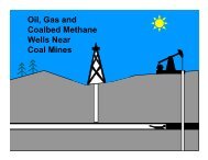
UNDERGROUND COAL GASIFICATION<br />
PRODUCTION WELL<br />
LIGNITE<br />
OVERBURDEN<br />
FORMATION<br />
GASIFICATION CHAMBER<br />
INJECTION WELL<br />
(AIR/OXYGEN)<br />
UCG is the insitu conversion <strong>of</strong><br />
unworkable (deep seated, thin<br />
seam, steep dipping) coal/lignite<br />
into a combustible product gas.<br />
UCG operation is initiated by<br />
drilling two adjacent boreholes<br />
into the coal seam <strong>and</strong> injecting<br />
pressurised oxidants like hot air,<br />
oxygen or steam into the coal<br />
seam, igniting the coal seam <strong>and</strong><br />
recovering the combustion gasses<br />
through the adjacent borehole.<br />
The connectivity between the<br />
injection <strong>and</strong> producer wells are<br />
made by special linking<br />
techniques.<br />
48
USES OF PRODUCT GAS<br />
• The UCG gases consists mainly a mixture <strong>of</strong><br />
Hydrogen, Carbon-monoxide, Methane, Carbondioxide<br />
<strong>and</strong> higher Hydrocarbons.<br />
• The raw gas after processing can be utilized for<br />
power generation in Integrated Gas combined<br />
cycle power plant <strong>of</strong> suitable capacity. The gas<br />
is also suitable for industrial heating or<br />
hydrogen <strong>and</strong> natural gas production.<br />
• NLC is interested in UCG <strong>and</strong> subsequent use <strong>of</strong><br />
gas in generating power.<br />
49
NLC’s UCG PROJECT<br />
NLC is pursuing two projects for<br />
pilot study for UCG in lignite.<br />
1.UCG Project under Coal S&T<br />
2.UCG Project under NLC <strong>and</strong> ONGC Joint<br />
venture.<br />
50
1. Project funded by Coal S&T, NLC <strong>and</strong> DST<br />
A UCG study project is to be undertaken in a<br />
suitable lignite block in Rajasthan.<br />
• Approved cost <strong>of</strong> the project : Rs.125 Lakhs<br />
• Project duration : 4 years<br />
• If the project studies are proved successful,<br />
commercial UCG operation would be initiated<br />
for utilization <strong>of</strong> the product gas in a suitable<br />
Integrated Gas Combined cycle(IGCC)Power<br />
plant.<br />
51
A project titled “Underground<br />
Coal Gasification (UCG) <strong>and</strong> its<br />
Utilization for power generation<br />
studies in lignite deposits in<br />
Rajasthan” is proposed to be<br />
undertaken by <strong>Neyveli</strong> <strong>Lignite</strong><br />
<strong>Corporation</strong> Limited in<br />
association with Internationally<br />
reputed UCG expert agency under<br />
Coal S&T grant <strong>of</strong> Ministry <strong>of</strong><br />
Coal, Government <strong>of</strong> India.<br />
52
TIME SCHEDULE<br />
53
Assistance required from<br />
USA for Consultancy<br />
Services for UCG Pilot<br />
studies undertaken by<br />
NLC through Coal S&T<br />
54
2 . NLC-ONGC UCG Projects<br />
• NLC has entered into an underst<strong>and</strong>ing with<br />
ONGC for undertaking a UCG project in deep<br />
seated lignite deposit in India.<br />
• Certain lignite blocks in Tamil Nadu ,Gujarat <strong>and</strong><br />
Rajasthan is being considered for undertaking<br />
preliminary UCG studies to assess their<br />
suitability.<br />
• The UCG studies will lead in deciding the future<br />
strategy about UCG development.<br />
55
Consequent to the Indo-US working group meeting on 04.04.2006<br />
letters were issued to following experts seeking assistance in UCG<br />
<strong>and</strong> CBM by NLC.<br />
Mr.Ravi Upadhye, Ph.D; PE<br />
Deputy Materials Program Leader<br />
for<br />
Energy &Environment<br />
University <strong>of</strong> California<br />
Livermore, CA 94551.<br />
Shri. Ajay Kumar,<br />
Economic Advisor, American<br />
Embassy,<br />
Chanakyapuri, New Delhi110 021<br />
Jonathan R.Kelafant<br />
Kumar M.Sellakumar<br />
Senior Vice President President<br />
ArligtonVA 2203<br />
ETAA Energy,INC<br />
PH/FAX (908) 252-9650 Bridge water NJ 08807<br />
Reminder letter was also issued during Nov’06 to Mr.Jonathan<br />
R.Kelafant <strong>and</strong> Mr.Kumar M.Sellakumar for CBM Study in<br />
Mannargudi <strong>Lignite</strong> Deposit<br />
Reply awaited<br />
56
Feasibility Study<br />
Preparation for Mine –III<br />
Alternate Mining Technology<br />
Availing USTDA Grant<br />
57
Mine –III Project<br />
•NLC has proposed to open Mine –III <strong>of</strong> 8 MTPA with<br />
linked 1000 MW TPS-III <strong>and</strong> GOI accorded sanction<br />
for Advance Action Proposal.<br />
•Feasibility Study for Mine –III was prepared<br />
adopting SME technology by NLC but Cost <strong>of</strong> Mining<br />
<strong>of</strong> lignite with SME technology was on higher side.<br />
•To reduce the Production cost, NLC started exploring<br />
Alternate Technologies particularly CME technology.<br />
•It is learnt that CME technology with higher size<br />
Equipments are successfully operating in US in large<br />
opencast mines.<br />
58
USTDA (US Trade <strong>and</strong><br />
Development Agency) Grant<br />
• In an informal session, US consulate<br />
<strong>of</strong>ficials has come forward <strong>and</strong> showed<br />
interest in extending help to NLC to make<br />
use <strong>of</strong> CME expertise available at US<br />
• Further it was expressed that the existence<br />
<strong>of</strong> service based <strong>and</strong> equipment based<br />
mining related companies are available in<br />
US for taking up the Feasibility Study <strong>and</strong><br />
subsequent development <strong>of</strong> business<br />
opportunities.<br />
59
USTDA – NLC Grant<br />
Agreement<br />
• In further development, an<br />
agreement between the Govt. <strong>of</strong><br />
USA, acting through USTDA <strong>and</strong> NLC<br />
was signed on 13.03.2006 for the<br />
Grant value <strong>of</strong> US $ 360,000 for the<br />
Technical Assistance for preparation<br />
<strong>of</strong> Feasibility Study on Alternate<br />
Mining Technology for Mine-III.<br />
60
RFP<br />
• Based on the agreement, a Request<br />
For Proposal (RFP) for the Technical<br />
Assistance on behalf <strong>of</strong> NLC, is<br />
hosted in the website <strong>of</strong> Federal<br />
Business Opportunities on<br />
21.06.2006.<br />
61
Response for RFP<br />
• Three US consultancy firms have<br />
responded for the RFP viz:<br />
1. Taylor – Dejongh & Tecolotes De<br />
La Noche Consulting, Washington DC<br />
2. John T. Boyd Company, Pittsburg,<br />
Penn State &<br />
3. Norwest <strong>Corporation</strong>, Salt Lake City,<br />
Utah<br />
62
Award <strong>of</strong> Contract<br />
• Under the Grant, M/s Norwest<br />
<strong>Corporation</strong>, Utah was selected for<br />
preparation <strong>of</strong> Feasibility Study on<br />
Alternate Mining Technology for Mine-III.<br />
• The contract agreement was signed on<br />
08.12.2006<br />
• All the required Particulars viz, geological<br />
data, topographical features <strong>of</strong> Mine III<br />
<strong>and</strong> Power Plant areas, relevant reports<br />
prepared by NLC, etc., have been<br />
furnished to M/s.Norwest <strong>Corporation</strong> as<br />
envisaged in the Contract Agreement.<br />
63
Report Submission<br />
• M/s Norwest <strong>Corporation</strong> has<br />
submitted the<br />
1. Inception Report on 22.12.06.<br />
2. Interim Report on 29.03.07<br />
• M/s Norwest <strong>Corporation</strong> is expected<br />
to submit the:<br />
1. Draft Report by July, 2007 &<br />
2. Final Report by September,2007<br />
64
Extension <strong>of</strong> Technology<br />
NLC may implement the selected<br />
technology for Mine-III project by M/s<br />
Norwest <strong>Corporation</strong> for NLC’s<br />
Jayamkondam Project (Capacity <strong>of</strong> the<br />
Mine is 13.5 MTPA <strong>of</strong> <strong>Lignite</strong> <strong>and</strong> 94.5<br />
Million Cubic Metres <strong>of</strong> Overburden) also,<br />
due to the similar Geological <strong>and</strong><br />
Hydrological conditions.<br />
65