USER MANUAL - Corrsys-Datron
USER MANUAL - Corrsys-Datron
USER MANUAL - Corrsys-Datron

You also want an ePaper? Increase the reach of your titles
YUMPU automatically turns print PDFs into web optimized ePapers that Google loves.
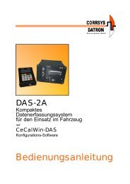
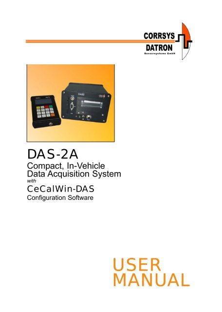
DAS-2A<br />
Compact, In-Vehicle<br />
Data Acquisition System<br />
with<br />
CeCalWin-DAS<br />
Configuration Software<br />
<strong>USER</strong><br />
<strong>MANUAL</strong>
User Manual<br />
DAS-2A Data Acquisition System with CeCalWin-DAS Software<br />
Notes:<br />
©2008 CORRSYS-DATRON Sensorsysteme GmbH, Germany DAS-2A_m-812-e-rev001 10/08 2
User Manual<br />
DAS-2A Data Acquisition System with CeCalWin-DAS Software<br />
Table of Contents<br />
Safety Instructions . . . . . . . . . . . . . . . . . . . . . . . . . . . . . . . . . . . . . . . . . . . . . . . . . . . . . . .7<br />
Volume I: DAS-2A System . . . . . . . . . . . . . . . . . . . . . . . . . . . . . . . . . . . . . . . . . . . .8<br />
1) Technical Specifications . . . . . . . . . . . . . . . . . . . . . . . . . . . . . . . . . . . . . . . . . . . . . . .8<br />
DAS-2 System Configurations . . . . . . . . . . . . . . . . . . . . . . . . . . . . . . . . . . . . . . . . . . . .10<br />
DAS-2 Pin Assignments . . . . . . . . . . . . . . . . . . . . . . . . . . . . . . . . . . . . . . . . . . . . . . . . .12<br />
2) Using the DAS-2A System . . . . . . . . . . . . . . . . . . . . . . . . . . . . . . . . . . . . . . . . . . . . .14<br />
About the DAS-2A Control/Display Unit . . . . . . . . . . . . . . . . . . . . . . . . . . . . . . .14<br />
Operating guidelines . . . . . . . . . . . . . . . . . . . . . . . . . . . . . . . . . . . . . . . . . . . . . . . .15<br />
Display Settings . . . . . . . . . . . . . . . . . . . . . . . . . . . . . . . . . . . . . . . . . . . . . . . . . . . .15<br />
Basic Control Functions . . . . . . . . . . . . . . . . . . . . . . . . . . . . . . . . . . . . . . . . . . . . . . .16<br />
Working with editable parameters . . . . . . . . . . . . . . . . . . . . . . . . . . . . . . . . . . . . .16<br />
Numeric values . . . . . . . . . . . . . . . . . . . . . . . . . . . . . . . . . . . . . . . . . . . . . . . . . . . . . .16<br />
To insert additional spaces for letters or numbers . . . . . . . . . . . . . . . . . . . . . . . . . . . . .16<br />
To delete letters or numbers . . . . . . . . . . . . . . . . . . . . . . . . . . . . . . . . . . . . . . . . . . . . . .16<br />
Positive/negative values . . . . . . . . . . . . . . . . . . . . . . . . . . . . . . . . . . . . . . . . . . . . . . . .16<br />
Decimal point location . . . . . . . . . . . . . . . . . . . . . . . . . . . . . . . . . . . . . . . . . . . . . . . . .16<br />
Pre-set options . . . . . . . . . . . . . . . . . . . . . . . . . . . . . . . . . . . . . . . . . . . . . . . . . . . . . . .16<br />
Passwords and names . . . . . . . . . . . . . . . . . . . . . . . . . . . . . . . . . . . . . . . . . . . . . . . . .16<br />
To exit a menu . . . . . . . . . . . . . . . . . . . . . . . . . . . . . . . . . . . . . . . . . . . . . . . . . . . . . . . .17<br />
System Menu . . . . . . . . . . . . . . . . . . . . . . . . . . . . . . . . . . . . . . . . . . . . . . . . . . . . . . . .17<br />
DATE, TIME SETTINGS . . . . . . . . . . . . . . . . . . . . . . . . . . . . . . . . . . . . . . . . . . . . .18<br />
SRAM INFO . . . . . . . . . . . . . . . . . . . . . . . . . . . . . . . . . . . . . . . . . . . . . . . . . . . . . .18<br />
SRAM FORMAT . . . . . . . . . . . . . . . . . . . . . . . . . . . . . . . . . . . . . . . . . . . . . . . . . . .18<br />
SERIAL NUMBER . . . . . . . . . . . . . . . . . . . . . . . . . . . . . . . . . . . . . . . . . . . . . . . . . .19<br />
SOFTWARE VERSION . . . . . . . . . . . . . . . . . . . . . . . . . . . . . . . . . . . . . . . . . . . . . . . . . . .19<br />
HARDWARE REVISION . . . . . . . . . . . . . . . . . . . . . . . . . . . . . . . . . . . . . . . . . . . . .19<br />
HARDWARE CONFIGURATION . . . . . . . . . . . . . . . . . . . . . . . . . . . . . . . . . . . . . . .20<br />
SET CONFIGURATION TO DEFAULT . . . . . . . . . . . . . . . . . . . . . . . . . . . . . . . . . . . . . .20<br />
PROTECTION . . . . . . . . . . . . . . . . . . . . . . . . . . . . . . . . . . . . . . . . . . . . . . . . . . . . .21<br />
START, VIEW, EDIT JOB: (the Main Menu) . . . . . . . . . . . . . . . . . . . . . . . . . . . . . . . . .23<br />
JOB SEQUENCE . . . . . . . . . . . . . . . . . . . . . . . . . . . . . . . . . . . . . . . . . . . . . . . . . . . . . . .23<br />
JOB1 - JOB10 . . . . . . . . . . . . . . . . . . . . . . . . . . . . . . . . . . . . . . . . . . . . . . . . . . . . . . . . . .23<br />
CALIBRATION . . . . . . . . . . . . . . . . . . . . . . . . . . . . . . . . . . . . . . . . . . . . . . . . . . . . . . . . . .23<br />
Setting-up a JOB SEQUENCE . . . . . . . . . . . . . . . . . . . . . . . . . . . . . . . . . . . . . . . .24<br />
Setting-up measurement configurations (JOB1 - JOB10) . . . . . . . . . . . . . . . . . . .25<br />
CHANNEL . . . . . . . . . . . . . . . . . . . . . . . . . . . . . . . . . . . . . . . . . . . . . . . . . . . . . . . . . . .26<br />
s (distance) . . . . . . . . . . . . . . . . . . . . . . . . . . . . . . . . . . . . . . . . . . . . . . . . . . . . . . . .28<br />
v (velocity) . . . . . . . . . . . . . . . . . . . . . . . . . . . . . . . . . . . . . . . . . . . . . . . . . . . . . . . .29<br />
a (acceleration) . . . . . . . . . . . . . . . . . . . . . . . . . . . . . . . . . . . . . . . . . . . . . . . . . . . .29<br />
LB (Light Barrier) . . . . . . . . . . . . . . . . . . . . . . . . . . . . . . . . . . . . . . . . . . . . . . . . . . .30<br />
BS (Brake Switch) . . . . . . . . . . . . . . . . . . . . . . . . . . . . . . . . . . . . . . . . . . . . . . . . . .30<br />
DIG2 (Digital Channel 2) . . . . . . . . . . . . . . . . . . . . . . . . . . . . . . . . . . . . . . . . . . . . .31<br />
DIG1 (Digital Channel 1) . . . . . . . . . . . . . . . . . . . . . . . . . . . . . . . . . . . . . . . . . . . . .32<br />
ANA1S (CORREVIT ® Sensor analog Channel 1) . . . . . . . . . . . . . . . . . . . . . . . . . . .33<br />
ANA2S (CORREVIT ® Sensor analog Channel 2) . . . . . . . . . . . . . . . . . . . . . . . . . . .34<br />
ANA1-8 (Analog Channel 1-8) . . . . . . . . . . . . . . . . . . . . . . . . . . . . . . . . . . . . . . . . .35<br />
RATE . . . . . . . . . . . . . . . . . . . . . . . . . . . . . . . . . . . . . . . . . . . . . . . . . . . . . . . . . . . .38<br />
START TRIGGER . . . . . . . . . . . . . . . . . . . . . . . . . . . . . . . . . . . . . . . . . . . . . . . . . . . . . . .38<br />
STOP TRIGGER . . . . . . . . . . . . . . . . . . . . . . . . . . . . . . . . . . . . . . . . . . . . . . . . . . . . .41<br />
TRIGGER HYSTERESIS . . . . . . . . . . . . . . . . . . . . . . . . . . . . . . . . . . . . . . . . . . . . . . .42<br />
AUTOSAVE . . . . . . . . . . . . . . . . . . . . . . . . . . . . . . . . . . . . . . . . . . . . . . . . . . . . . . . . .43<br />
SOUND . . . . . . . . . . . . . . . . . . . . . . . . . . . . . . . . . . . . . . . . . . . . . . . . . . . . . . . . . . .44<br />
<strong>USER</strong> DISPLAY1 - 3 . . . . . . . . . . . . . . . . . . . . . . . . . . . . . . . . . . . . . . . . . . . . . . . . .46<br />
END DISPLAY . . . . . . . . . . . . . . . . . . . . . . . . . . . . . . . . . . . . . . . . . . . . . . . . . . . . . . . . .48<br />
PRINT . . . . . . . . . . . . . . . . . . . . . . . . . . . . . . . . . . . . . . . . . . . . . . . . . . . . . . . . . . .51<br />
FILE CHANNELS . . . . . . . . . . . . . . . . . . . . . . . . . . . . . . . . . . . . . . . . . . . . . . . . . . . .58<br />
JOB NAMES . . . . . . . . . . . . . . . . . . . . . . . . . . . . . . . . . . . . . . . . . . . . . . . . . . . . . . . .59<br />
OFFSET CALIBRATION . . . . . . . . . . . . . . . . . . . . . . . . . . . . . . . . . . . . . . . . . . . . . .60<br />
CALIBRATION . . . . . . . . . . . . . . . . . . . . . . . . . . . . . . . . . . . . . . . . . . . . . . . . . . . . . . . . . . . .61<br />
©2008 CORRSYS-DATRON Sensorsysteme GmbH, Germany DAS-2A_m-812-e-rev001 10/08 3
User Manual<br />
DAS-2A Data Acquisition System with CeCalWin-DAS Software<br />
Table of Contents (continued)<br />
3) Testing with the DAS2-A Control/Display Unit . . . . . . . . . . . . . . . . . . . . . . . . . . .66<br />
How to perform a test measurement . . . . . . . . . . . . . . . . . . . . . . . . . . . . . . . . . . . . . . .67<br />
To view a single parameter in the larger display format . . . . . . . . . . . . . . . . . . . . . . . . . .69<br />
To Print or View a Saved Job . . . . . . . . . . . . . . . . . . . . . . . . . . . . . . . . . . . . . . . . . . . . . . . . . .70<br />
Working with the optional LED display . . . . . . . . . . . . . . . . . . . . . . . . . . . . . . . . . . . . . .71<br />
DAS-2A Printer: Replacing the printer paper roll . . . . . . . . . . . . . . . . . . . . . . . . . . . . . . .72<br />
Volume II: Using CeCalWin-DAS2 Software . . . . . . . . . . . . . . . . . . . .74<br />
1) Introduction . . . . . . . . . . . . . . . . . . . . . . . . . . . . . . . . . . . . . . . . . . . . . . . . . . . . . . . . . .74<br />
About software installation . . . . . . . . . . . . . . . . . . . . . . . . . . . . . . . . . . . . . . . . . . . . . . .74<br />
2) Working in CeCalWin-DAS . . . . . . . . . . . . . . . . . . . . . . . . . . . . . . . . . . . . . . . . . . . . .75<br />
Main Program Window Overview . . . . . . . . . . . . . . . . . . . . . . . . . . . . . . . . . . . .75<br />
Project Window Overview . . . . . . . . . . . . . . . . . . . . . . . . . . . . . . . . . . . . . . . . . . .75<br />
Menu Bar . . . . . . . . . . . . . . . . . . . . . . . . . . . . . . . . . . . . . . . . . . . . . . . . . . . . . . . .76<br />
Tool Bar . . . . . . . . . . . . . . . . . . . . . . . . . . . . . . . . . . . . . . . . . . . . . . . . . . . . . . . . . .79<br />
Status Bar . . . . . . . . . . . . . . . . . . . . . . . . . . . . . . . . . . . . . . . . . . . . . . . . . . . . . . . .79<br />
Project Window Tabs . . . . . . . . . . . . . . . . . . . . . . . . . . . . . . . . . . . . . . . . . . . . . . . .80<br />
Measurement Settings . . . . . . . . . . . . . . . . . . . . . . . . . . . . . . . . . . . . . . . . . . . . . . . . .81<br />
JOB1-JOB10 . . . . . . . . . . . . . . . . . . . . . . . . . . . . . . . . . . . . . . . . . . . . . . . . . . . . . . .81<br />
Versions . . . . . . . . . . . . . . . . . . . . . . . . . . . . . . . . . . . . . . . . . . . . . . . . . . . . . . . . .81<br />
Features . . . . . . . . . . . . . . . . . . . . . . . . . . . . . . . . . . . . . . . . . . . . . . . . . . . . . . . . . .82<br />
Common mask for Job file names . . . . . . . . . . . . . . . . . . . . . . . . . . . . . . . . . . . . . . .82<br />
Setting-up a job: Section Overview . . . . . . . . . . . . . . . . . . . . . . . . . . . . . . . . . .83<br />
Setting-up a job: Channels . . . . . . . . . . . . . . . . . . . . . . . . . . . . . . . . . . . . . . . . . .84<br />
t (time) . . . . . . . . . . . . . . . . . . . . . . . . . . . . . . . . . . . . . . . . . . . . . . . . . . . . . . . . . . .85<br />
s (distance) . . . . . . . . . . . . . . . . . . . . . . . . . . . . . . . . . . . . . . . . . . . . . . . . . . . . . . .86<br />
v (velocity) . . . . . . . . . . . . . . . . . . . . . . . . . . . . . . . . . . . . . . . . . . . . . . . . . . . . . . . .87<br />
a (acceleration) . . . . . . . . . . . . . . . . . . . . . . . . . . . . . . . . . . . . . . . . . . . . . . . . . . . .88<br />
DIG2 (digital channel 2) . . . . . . . . . . . . . . . . . . . . . . . . . . . . . . . . . . . . . . . . . . . . . .89<br />
DIG1 (digital channel 1) . . . . . . . . . . . . . . . . . . . . . . . . . . . . . . . . . . . . . . . . . . . . .90<br />
LB (light barrier) . . . . . . . . . . . . . . . . . . . . . . . . . . . . . . . . . . . . . . . . . . . . . . . . . . . .91<br />
LBCNT (light barrier counter) . . . . . . . . . . . . . . . . . . . . . . . . . . . . . . . . . . . . . . . . . .92<br />
BS (brake switch) . . . . . . . . . . . . . . . . . . . . . . . . . . . . . . . . . . . . . . . . . . . . . . . . . . . .93<br />
ANA1S (CORREVIT ® Sensor analog channel 1) . . . . . . . . . . . . . . . . . . . . . . . . . . . .94<br />
ANA2S (CORREVIT ® Sensor analog channel 2) . . . . . . . . . . . . . . . . . . . . . . . . . . . .95<br />
ANA1 ... ANA8 . . . . . . . . . . . . . . . . . . . . . . . . . . . . . . . . . . . . . . . . . . . . . . . . . . . . .96<br />
Setting-up a job: General settings . . . . . . . . . . . . . . . . . . . . . . . . . . . . . . . . . . .97<br />
Rate . . . . . . . . . . . . . . . . . . . . . . . . . . . . . . . . . . . . . . . . . . . . . . . . . . . . . . . . . . .98<br />
Trigger hysteresis . . . . . . . . . . . . . . . . . . . . . . . . . . . . . . . . . . . . . . . . . . . . . . . . . .98<br />
Autosave . . . . . . . . . . . . . . . . . . . . . . . . . . . . . . . . . . . . . . . . . . . . . . . . . . . . . . . . .98<br />
Start trigger and Stop trigger . . . . . . . . . . . . . . . . . . . . . . . . . . . . . . . . . . . . . . . . . . .99<br />
Setting-up a job: Display settings . . . . . . . . . . . . . . . . . . . . . . . . . . . . . . . . . . .103<br />
User display 1 through 3 . . . . . . . . . . . . . . . . . . . . . . . . . . . . . . . . . . . . . . . . . . . . . . . . . .104<br />
End values . . . . . . . . . . . . . . . . . . . . . . . . . . . . . . . . . . . . . . . . . . . . . . . . . . . . . . . . .105<br />
Print Mode . . . . . . . . . . . . . . . . . . . . . . . . . . . . . . . . . . . . . . . . . . . . . . . . . . . . . . . . . .106<br />
Show Mode . . . . . . . . . . . . . . . . . . . . . . . . . . . . . . . . . . . . . . . . . . . . . . . . . . . . . . . . . . .106<br />
Setting-up a job: Sound settings . . . . . . . . . . . . . . . . . . . . . . . . . . . . . . . . . . . .107<br />
Trigger sound mode . . . . . . . . . . . . . . . . . . . . . . . . . . . . . . . . . . . . . . . . . . . . . . . . . . . .108<br />
Range sound mode . . . . . . . . . . . . . . . . . . . . . . . . . . . . . . . . . . . . . . . . . . . . . . . . . . . . .108<br />
Range sound signal . . . . . . . . . . . . . . . . . . . . . . . . . . . . . . . . . . . . . . . . . . . . . . . . . . . .109<br />
Sound range . . . . . . . . . . . . . . . . . . . . . . . . . . . . . . . . . . . . . . . . . . . . . . . . . . . . . . . . . .109<br />
©2008 CORRSYS-DATRON Sensorsysteme GmbH, Germany DAS-2A_m-812-e-rev001 10/08 4
User Manual<br />
DAS-2A Data Acquisition System with CeCalWin-DAS Software<br />
Table of Contents (continued)<br />
Setting-up a job: Print settings . . . . . . . . . . . . . . . . . . . . . . . . . . . . . . . . . . . . .110<br />
Status . . . . . . . . . . . . . . . . . . . . . . . . . . . . . . . . . . . . . . . . . . . . . . . . . . . . . . . . . . .110<br />
Column Separator . . . . . . . . . . . . . . . . . . . . . . . . . . . . . . . . . . . . . . . . . . . . . . . . .111<br />
Print Mode . . . . . . . . . . . . . . . . . . . . . . . . . . . . . . . . . . . . . . . . . . . . . . . . . . . . . . . . . . .111<br />
Acceleration . . . . . . . . . . . . . . . . . . . . . . . . . . . . . . . . . . . . . . . . . . . . . . . . . . . . . . . . . .111<br />
Decimal Separator . . . . . . . . . . . . . . . . . . . . . . . . . . . . . . . . . . . . . . . . . . . . . . . . .111<br />
Header . . . . . . . . . . . . . . . . . . . . . . . . . . . . . . . . . . . . . . . . . . . . . . . . . . . . . . . . . .111<br />
Extrapolation . . . . . . . . . . . . . . . . . . . . . . . . . . . . . . . . . . . . . . . . . . . . . . . . . . . . .111<br />
Column . . . . . . . . . . . . . . . . . . . . . . . . . . . . . . . . . . . . . . . . . . . . . . . . . . . . . . . . .112<br />
Statistics . . . . . . . . . . . . . . . . . . . . . . . . . . . . . . . . . . . . . . . . . . . . . . . . . . . . . . . .113<br />
Extra Value . . . . . . . . . . . . . . . . . . . . . . . . . . . . . . . . . . . . . . . . . . . . . . . . . . . . . .113<br />
Setting-up a job: File settings . . . . . . . . . . . . . . . . . . . . . . . . . . . . . . . . . . . . . .114<br />
File signals . . . . . . . . . . . . . . . . . . . . . . . . . . . . . . . . . . . . . . . . . . . . . . . . . . . . . .114<br />
File name . . . . . . . . . . . . . . . . . . . . . . . . . . . . . . . . . . . . . . . . . . . . . . . . . . . . . . . .114<br />
Setting-up a job: Offset calibration . . . . . . . . . . . . . . . . . . . . . . . . . . . . . . . . . . .115<br />
Setting-up a job: Job sequence . . . . . . . . . . . . . . . . . . . . . . . . . . . . . . . . . . . . .116<br />
Position 1-5 . . . . . . . . . . . . . . . . . . . . . . . . . . . . . . . . . . . . . . . . . . . . . . . . . . . . . . . . . .116<br />
Loop count . . . . . . . . . . . . . . . . . . . . . . . . . . . . . . . . . . . . . . . . . . . . . . . . . . . . . . . . . . . . . .116<br />
Data Center Settings . . . . . . . . . . . . . . . . . . . . . . . . . . . . . . . . . . . . . . . . . . . . . .117<br />
Data directory . . . . . . . . . . . . . . . . . . . . . . . . . . . . . . . . . . . . . . . . . . . . . . . . . . . .117<br />
ASCII directory . . . . . . . . . . . . . . . . . . . . . . . . . . . . . . . . . . . . . . . . . . . . . . . . . . . .119<br />
BIOS Settings . . . . . . . . . . . . . . . . . . . . . . . . . . . . . . . . . . . . . . . . . . . . . . . . . . . . .121<br />
Volume III: Appendix . . . . . . . . . . . . . . . . . . . . . . . . . . . . . . . . . . . . . . . . . . .122<br />
A) Software Installation . . . . . . . . . . . . . . . . . . . . . . . . . . . . . . . . . . . . . . . . . . . . . . . . . . . . .123<br />
B) Updating the Firmware . . . . . . . . . . . . . . . . . . . . . . . . . . . . . . . . . . . . . . . . . . . . . . . . . . .127<br />
C) Job Sequences . . . . . . . . . . . . . . . . . . . . . . . . . . . . . . . . . . . . . . . . . . . . . . . . . . . . . . . .128<br />
D) Sensor Connections . . . . . . . . . . . . . . . . . . . . . . . . . . . . . . . . . . . . . . . . . . . . . . . . . . . . .131<br />
©2008 CORRSYS-DATRON Sensorsysteme GmbH, Germany DAS-2A_m-812-e-rev001 10/08 5
User Manual<br />
DAS-2A Data Acquisition System with CeCalWin-DAS Software<br />
General Information<br />
Legal Notice<br />
Information furnished is believed to be accurate and reliable. However, CORRSYS-DATRON assumes no<br />
responsibility for the consequences of use of such information, nor for any infringement of patents or other<br />
rights of third parties which may result from its use. No license is granted by implication or otherwise under<br />
any patent or patent rights of CORRSYS-DATRON. Specifications mentioned in this publication are<br />
subject to change without notice and do not represent a commitment on the part of CORRSYS-DATRON.<br />
This publication supersedes and replaces all information previously supplied.<br />
All brand names are trademarks of their respective holders.<br />
Copyright Notice<br />
© Copyright 2008, CORRSYS-DATRON<br />
Revision<br />
DAS-2A_m-812-e-rev001 10/08<br />
Contact<br />
International Headquarters:<br />
CORRSYS-DATRON Sensorsysteme GmbH<br />
Charlotte-Bamberg-Str. 12<br />
35578 Wetzlar / Germany<br />
Phone ++49 (6441) 9282-0<br />
Fax ++49 (6441) 9282-17<br />
E-mail sales@corrsys-datron.com<br />
URL www.corrsys-datron.com<br />
North American Headquarters:<br />
CORRSYS-DATRON Sensorsystems, Inc.<br />
40000 Grand River, Suite 503<br />
Novi, MI 48375 / USA<br />
Phone ++1 (248) 615-2035<br />
Toll-free++1 (800) 832-0732<br />
Fax ++1 (248) 615-2184<br />
E-mail USA-sales@corrsys-datron.com<br />
URL www.corrsys-datron.com<br />
Chinese Haedquarters:<br />
CORRSYS-DATRON Sensorsysteme GmbH, China Office<br />
Room 708, JinTianDi International Mansion,<br />
No. 998 RenMin Road, Shanghai (200021), P.R.China<br />
Tel.: ++86-21-63114144<br />
Fax: ++86-21-63114154<br />
E-mail: Xiaoying.Li@corrsys-datron.com.cn<br />
URL: www.corrsys-datron.com.cn<br />
©2008 CORRSYS-DATRON Sensorsysteme GmbH, Germany DAS-2A_m-812-e-rev001 10/08 6
User Manual<br />
DAS-2A Data Acquisition System with CeCalWin-DAS Software<br />
Safety Instructions<br />
Please read carefully before operating the equipment.<br />
CORRSYS-DATRON is not responsible for damage that may occur when this system is used in<br />
any way other than that for which it is intended.<br />
To assure safe and proper operation, all supplied equipment, components and/or accessories must be<br />
carefully transported and stored, as well as professionally installed and operated. Careful maintenance<br />
and usage in full accordance with operating instructions is imperative.<br />
CORRSYS-DATRON equipment should be installed and operated only by qualified persons who are<br />
familiar with devices of this type.<br />
Local regulations may not permit the operation of motor vehicles on public highways while the<br />
equipment is mounted on the exterior of the vehicle.<br />
• Use the equipment only for intended applications. Improper application is not advised.<br />
• Do not modify or change the equipment or its accessories in any way.<br />
• Improper use or mounting of the equipment may affect the safety of the vehicle and/or occupants.<br />
• The equipment must not be mounted and/or operated in any way that may compromise vehicle or<br />
and/or occupant safety.<br />
• Equipment must be mounted firmly and securely.<br />
• Use only original equipment, components and/or accessories included in the scope of delivery.<br />
• Do not mount equipment, components and/or accessories near heat sources (e.g. exhaust).<br />
• Do not use defective or damaged equipment, components and/or accessories .<br />
• Always note correct pin assignments and operating voltages when connecting equipment to<br />
power supplies, data acquisition/evaluation systems, and/or any other applicable system or<br />
component. Equipment may be damaged if not properly connected and/or operated.<br />
• Do not mount the DAS-2A unit, control/display unit, monitor(s), or any other item in any location that<br />
may come into contact with the airbag in the event of air bag deployment.<br />
• If the DAS-2A unit, control/display unit, monitor(s), or any other item is placed in the passenger seat,<br />
deactivate the air bag to prevent accidental contact with the airbag in the event of air bag deployment.<br />
• For additional information, please contact the CORRSYS-DATRON service department.<br />
©2008 CORRSYS-DATRON Sensorsysteme GmbH, Germany DAS-2A_m-812-e-rev001 10/08 7
User Manual<br />
DAS-2A Data Acquisition System with CeCalWin-DAS Software<br />
Volume I: DAS2-A System<br />
1) Technical Specifications<br />
Measurements:<br />
Weight:<br />
approx. 190 x 115 x 35mm (display)<br />
approx. 220 x 145 x 80mm (DAS-2Ax)<br />
approx. 220 x 175 x 115mm (DAS-AxD)<br />
approx. 0.45 kg (display)<br />
approx. 1.5 kg (DAS-2Ax)<br />
approx. 2.5 kg (DAS-2AxD)<br />
Voltage supply: 9…18V DC, approx. 300 mA (DAS2-Ax)<br />
approx. 450 mA (DAS2-AxD)*<br />
with reverse polarity protection<br />
Safety fuse:<br />
Temperature range:<br />
Storage medium:<br />
Interfaces:<br />
T 3.0 A<br />
operation: 0° to 70° C<br />
storage: -15° to 85° C<br />
SRAM card, up 8 MB capacity<br />
COM interface (RS232) for PC connection<br />
Printer interface (RS232), at DAS2-AxD not coming out<br />
Display interface (CAN) for connecting the LCD display<br />
and other display units<br />
Signal inputs:<br />
1) Sensor input (SEN) for CORREVIT ® Sensors,<br />
which includes one digital and two analog inputs:<br />
Digital:<br />
Analog 1:<br />
Analog 2:<br />
RS485 compatible<br />
threshold Level: 2.5V<br />
max. input frequency: 300kHz<br />
min. pulse width: > 1μs<br />
voltage range: 0 .. 10V<br />
input resistance: 400 k<br />
resolution: 10 bit<br />
voltage range: -10V .. 10V<br />
input resistance: 400 k<br />
resolution: 10 bit<br />
1) Counter input (DIG1) input range: 0…5V<br />
threshold Level: 2.5V<br />
max. input frequency: 300kHz<br />
1) Frequency-input (DIG2) switchable between pulse/time and<br />
1/period constant measurement<br />
input range: 0…5V<br />
threshold Level: 2.5V<br />
max. input frequency: 5kHz<br />
2) Switch-input (LB, BS) for light barrier and brake switch<br />
input range: 0…5V<br />
threshold Level: 2.5V<br />
max. input frequency: 100kHz<br />
*Units with onboard printer require up to four times more current than units not equipped with printer.<br />
©2008 CORRSYS-DATRON Sensorsysteme GmbH, Germany DAS-2A_m-812-e-rev001 10/08 8
User Manual<br />
DAS-2A Data Acquisition System with CeCalWin-DAS Software<br />
1) Technical Specifications (continued)<br />
Signal inputs:<br />
DAS-2A4x<br />
4 analog inputs<br />
DAS-2A8x<br />
8 analog inputs<br />
max. voltage range: -10V…10V<br />
input resistance : 400k<br />
input frequency: 300Hz<br />
resolution: 10 bit<br />
Max. power load: Voltages on the individual inputs range from 5V to 12V.<br />
Input amperage cannot exceed a combined total of 625mA.<br />
Inputs rated at 5V cannot exceed a combined total of 200mA.<br />
©2008 CORRSYS-DATRON Sensorsysteme GmbH, Germany DAS-2A_m-812-e-rev001 10/08 9
User Manual<br />
DAS-2A Data Acquisition System with CeCalWin-DAS Software<br />
DAS-2 System Configurations<br />
DAS2<br />
DAS2-A<br />
Inputs<br />
(0) analog<br />
(1) for CORRSYS-DATRON Distance Sensors<br />
(1) digital, counter<br />
(1) digital, switchable to counter or pulse-width<br />
(1) brake switch (optional: brake-light circuit)<br />
(1) light barrier<br />
DAS2-A4<br />
Inputs<br />
(4) analog<br />
(1) for CORRSYS-DATRON Distance Sensors<br />
(1) digital, counter<br />
(1) digital, switchable to counter or pulse-width<br />
(1) brake switch (optional: brake-light circuit)<br />
(1) light barrier<br />
DAS2-A8<br />
Inputs<br />
(8) analog<br />
(1) for CORRSYS-DATRON Distance Sensors<br />
(1) digital, counter<br />
(1) digital, switchable to counter or pulse-width<br />
(1) brake switch (optional: brake-light circuit)<br />
(1) light barrier<br />
©2008 CORRSYS-DATRON Sensorsysteme GmbH, Germany DAS-2A_m-812-e-rev001 10/08 10
User Manual<br />
DAS-2A Data Acquisition System with CeCalWin-DAS Software<br />
DAS-2 System Configurations (continued)<br />
DAS2<br />
with onboard printer<br />
DAS2-AD<br />
Inputs<br />
(0) analog<br />
(1) for CORRSYS-DATRON Distance Sensors<br />
(1) digital, counter<br />
(1) digital, switchable to counter or pulse-width<br />
(1) brake switch (optional: brake-light circuit)<br />
(1) light barrier<br />
DAS2-A4D<br />
Inputs<br />
(4) analog<br />
(1) for CORRSYS-DATRON Distance Sensors<br />
(1) digital, counter<br />
(1) digital, switchable to counter or pulse-width<br />
(1) brake switch (optional: brake-light circuit)<br />
(1) light barrier<br />
DAS2-A8D<br />
Inputs<br />
(8) analog<br />
(1) for CORRSYS-DATRON Distance Sensors<br />
(1) digital, counter<br />
(1) digital, switchable to counter or pulse-width<br />
(1) brake switch (optional: brake-light circuit)<br />
(1) light barrier<br />
©2008 CORRSYS-DATRON Sensorsysteme GmbH, Germany DAS-2A_m-812-e-rev001 10/08 11
User Manual<br />
DAS-2A Data Acquisition System with CeCalWin-DAS Software<br />
DAS-2 Pin Assignments<br />
3 9 2<br />
4 1<br />
5 8<br />
6<br />
10<br />
7<br />
Sensor Input (SEN) 10-pin Lemo, Series 2S<br />
Dedicated input for<br />
CORREVIT ® Sensors<br />
ATTENTION!<br />
All views are of the front of the connector.<br />
1) GNDA<br />
2) sensor analog 1<br />
3) sensor analog 2<br />
4) GNDA<br />
5) sensor digital high<br />
6) sensor digital low<br />
7) GND<br />
8) +12V<br />
9) n.c.<br />
10) n.c.<br />
3 2<br />
Digital 1 Input (DIG1) 3-pin Lemo, Series 1S<br />
Counter input<br />
0…5V<br />
1) digital 1 signal<br />
2) GND<br />
3) +12V<br />
1<br />
3 2<br />
Digital 2 Input (DIG2) 3-pin Lemo, Series 1S<br />
Frequency input<br />
0…5V<br />
1) digital 2 signal<br />
2) GND<br />
3) +12V<br />
1<br />
1 6<br />
3<br />
4<br />
Analog Input (ANA 1-8) 6-pin Lemo, Series 1S, female<br />
Differential input<br />
10 bit resolution<br />
1) +5V<br />
2) +12V<br />
3) analog in, negative (-)<br />
4) GNDA<br />
5) analog in, positive (+)<br />
6) GND<br />
3 2<br />
Light Barrier Input (LB) 3-pin Lemo, Series 1S<br />
Voltage input<br />
0…5V<br />
1) light barrier signal<br />
2) GND<br />
3) +12V<br />
1<br />
2 1<br />
Brake Switch Input (BS) 2-pin Lemo, Series 1S<br />
Voltage input<br />
0…5V<br />
1) brake switch signal<br />
2) GND<br />
©2008 CORRSYS-DATRON Sensorsysteme GmbH, Germany DAS-2A_m-812-e-rev001 10/08 12
User Manual<br />
DAS-2A Data Acquisition System with CeCalWin-DAS Software<br />
DAS-2 Pin Assignments (continued)<br />
1<br />
2 5<br />
3<br />
4<br />
ATTENTION!<br />
All views are of the front of the connector.<br />
Display Cable Connector 5-pin Lemo, Series 1B, male<br />
CAN connection<br />
1) CANL<br />
2) GND<br />
3) CANH<br />
4) VCC<br />
5) n.c.<br />
1<br />
5 2<br />
4 3<br />
Display Input/Output 5-pin Lemo, Series 1B, female<br />
CAN input on Display Unit<br />
1) CANL<br />
2) GND<br />
3) CANH<br />
4) VCC<br />
5) n.c.<br />
5 1<br />
4 3<br />
2<br />
COM1 5-pin Binder, Series 719, female<br />
For connection to PC<br />
1) TXD1<br />
2) RXD1<br />
3) GND<br />
4) n.c.<br />
5) n.c.<br />
5<br />
1<br />
AUX 9-pin DSUB, female<br />
9<br />
6<br />
OPTO1 and OPTO2<br />
sensor inputs<br />
1) OPTO1 input 6) OPTO GND<br />
2) OPTO2 input 7) sensor analog 1<br />
3) sensor digital high 8) sensor analog 2<br />
4) +12V 9) GNDA<br />
5) GND<br />
1<br />
5<br />
Printer 9-pin DSUB, male<br />
6<br />
9<br />
Output to external printer 1) n.c. 6) RTS2<br />
2) RXD2 7) bridge to 8<br />
3) TXD2 8) bridge to 7<br />
4) CTS2 9) n.c.<br />
5) GND<br />
2 1<br />
3 4<br />
Power In 4-pin male<br />
Input for system power<br />
1) 9…18V DC = +UB<br />
2) 9…18V DC = +UB<br />
3) GND = -UB<br />
4) GND = -UB<br />
©2008 CORRSYS-DATRON Sensorsysteme GmbH, Germany DAS-2A_m-812-e-rev001 10/08 13
User Manual<br />
DAS-2A Data Acquisition System with CeCalWin-DAS Software<br />
2) Using the DAS-2A System<br />
About the DAS-2A Control/Display Unit<br />
The DAS-2A Control/Display unit is designed to serve as an easy-to-use control surface and<br />
display interface for in-vehicle measurement and testing applications. Its logical, uncomplicated<br />
interface is designed to enable drivers to start, stop and monitor tests and measurements<br />
safely, easily and without the assistance of an additional technician. The DAS-2A Control/Display<br />
unit also provides the capability to view and configure most available system features and functions.<br />
NOTE: For extended capacity and increased efficiency in system and test configuration,<br />
connect the DAS-2A to a PC or laptop via the serial interface and use the included CeCalWin-<br />
DAS Windows*-compatible software. Please refer to Volume II: Using CeCalWin-DAS<br />
Software, which begins on page 74, for complete system configuration and test set-up<br />
instructions.<br />
©2008 CORRSYS-DATRON Sensorsysteme GmbH, Germany DAS-2A_m-812-e-rev001 10/08 14
User Manual<br />
DAS-2A Data Acquisition System with CeCalWin-DAS Software<br />
Operating guidelines<br />
When the DAS-2A System is powered-on, the following two screens are displayed, in succession:<br />
Next, the MAIN MENU will be displayed.<br />
Display Settings<br />
Display contrast can be adjusted for optimal presentation at different viewing angles, in varying<br />
ambient light conditions, etc. To adjust the Contrast setting, press ALT, then ACAL. The word, Contrast<br />
will appear in the upper-right corner of the display. Use the PGUP ⁄ and PGDWN<br />
buttons to adjust contrast as desired, then confirm the setting by pressing ENTER.<br />
©2008 CORRSYS-DATRON Sensorsysteme GmbH, Germany DAS-2A_m-812-e-rev001 10/08 15
User Manual<br />
DAS-2A Data Acquisition System with CeCalWin-DAS Software<br />
Basic Control Functions<br />
The DAS-2A Control/Display unit is easy to operate and requires knowledge of just a few basic functions:<br />
• Use the PGUP ⁄ and PGDWN buttons to move the cursor up and down, and the ¤and ˘<br />
buttons to move the cursor left or right, respectively.<br />
• When a user-editable field is highlighted with the cursor, the value or parameter in the field will<br />
flash, indicating that the selected value or parameter can be edited.<br />
A highlighted field<br />
Working with editable parameters<br />
Numeric values: to change a numeric value, use the ¤ and ˘ buttons to move the cursor to a<br />
specific desired position within a numeric value, then press ENTER. The selected position within the<br />
value will flash, indicating that it can be edited. Press ⁄ to increase the value, or to decrease the value.<br />
NOTE: the ⁄ and keys must be pressed once for each one-unit increase or decrease in value. Values<br />
will not continue to increase or decrease as the ⁄ and keys are pressed and held.<br />
To insert additional spaces for letters or numbers: Highlight the desired position and press<br />
INS (the INSERT key). An additional space will be added in which the default value of zero will be<br />
displayed. This value can then be edited as required.<br />
To delete letters or numbers: Highlight the desired position and press DEL, which is the delete key.<br />
Positive/negative values: by default, all numeric values are positive, and function as such until they<br />
are intentionally changed. This assignment is indicated by a blank space to the immediate left of the<br />
numeric value. To assign a negative value, use the ¤or ˘ buttons to move the cursor and highlight the<br />
space to the immediate left of the numeric value, then press ENTER. Once selected, the<br />
positive/negative position will flash, indicating that it can be edited. Next, press either the PGUP ⁄,<br />
PGDWN , or ENTER button once to activate the minus sign (-). To deactivate the minus sign (-), press<br />
either the PGUP ⁄, PGDWN , or ENTER button a second time. NOTE: When a negative value is<br />
assigned, the numeric value will automatically change to the minimum allowable value for the parameter<br />
being edited (ex. 0.001). To display a value with 3 digits again, press ENTER, then set the numeric value<br />
as required using the procedure described in Numeric Values, above.<br />
Decimal point location: to move the decimal point within a numeric value, use the ¤or ˘ buttons,<br />
to highlight the decimal point in its present location. Once selected, the decimal position will flash,<br />
indicating that it can be edited. Next, press the PGUP ⁄ button to move the point to the right, or PGDWN<br />
to move the point to the left.<br />
Pre-set options: for menus in which only specific, pre-set options are available, selections can be<br />
chosen by pressing the ¤and ˘ buttons, or by pressing ENTER.<br />
Passwords and names: JOB and FILE names, passwords, etc. can be entered using alphanumeric<br />
characters. To enter a character, highlight the desired position and press ENTER. Next, use the PGUP ⁄<br />
and PGDWN keys to scroll through the available characters, which include:<br />
• Upper-case letters (A-Z)<br />
• Numbers (0-9)<br />
• Lower-case letters (a-z)<br />
• The underscore (_)<br />
Repeat this process for each required character.<br />
See JOB NAMES, page 59, for additional details about names.<br />
©2008 CORRSYS-DATRON Sensorsysteme GmbH, Germany DAS-2A_m-812-e-rev001 10/08 16
User Manual<br />
DAS-2A Data Acquisition System with CeCalWin-DAS Software<br />
To exit a menu<br />
If the value is flashing - press the ESC (ESCAPE) button.<br />
If the value is not flashing -use the PGUP ⁄ or PGDWN<br />
always located at the bottom of every menu list).<br />
buttons to select RETURN (which is<br />
NOTE: Either option will return you to the previous menu. When working with sub-menus, repeat the<br />
procedure until you reach the desired menu level. All edited parameters will be saved automatically.<br />
System Menu<br />
The System Menu includes settings and information pertaining to the overall functionality and capacity<br />
of the DAS-2A System.<br />
To view the DAS-2A System Menu - press ALT, then ESC (SYS. MENU).<br />
To view settings/information for each of the System Menu categories - use the PGUP<br />
⁄ or PGDWN buttons to select the desired category, then press ENTER.<br />
The System Menu includes the following categories:<br />
System Menu details continue next page<br />
©2008 CORRSYS-DATRON Sensorsysteme GmbH, Germany DAS-2A_m-812-e-rev001 10/08 17
User Manual<br />
DAS-2A Data Acquisition System with CeCalWin-DAS Software<br />
System Menu (continued)<br />
DATE, TIME SETTINGS: Date and time settings used by the DAS-2A System. Time can be set as<br />
required via the standard numeric editing procedure.<br />
SRAM INFO: Information about the installed SRAM card, including total capacity and available (free)<br />
space.<br />
SRAM FORMAT: Provides access to the option to format the SRAM card. Select YES to format the<br />
SRAM card or NO to exit the menu without formatting the SRAM card. ATTENTION! All data stored<br />
on the SRAM card will be deleted when the card is formatted.<br />
System Menu details continue next page<br />
©2008 CORRSYS-DATRON Sensorsysteme GmbH, Germany DAS-2A_m-812-e-rev001 10/08 18
User Manual<br />
DAS-2A Data Acquisition System with CeCalWin-DAS Software<br />
System Menu (continued)<br />
SERIAL NUMBER: The serial number of the DAS-2A unit.<br />
SW VERSION: The firmware version-number, including the date and time the firmware was completed.<br />
HW REVISION: The hardware revision-number of the DAS-2A.<br />
System Menu details continue next page<br />
©2008 CORRSYS-DATRON Sensorsysteme GmbH, Germany DAS-2A_m-812-e-rev001 10/08 19
User Manual<br />
DAS-2A Data Acquisition System with CeCalWin-DAS Software<br />
System Menu (continued)<br />
HW CONFIGURATION: Information about the hardware with which the system is configured,<br />
including analog and digital inputs (not including the dedicated CORREVIT ® sensor input), and<br />
onboard of external printers.<br />
SET CFG TO DEFAULT: This function allows all system parameters to be returned to original factory<br />
settings. Choose YES to reset or NO to exit the menu without resetting system configuration parameters.<br />
The reset function provides an easy means to restore system function in the event of a freeze, crash or<br />
other malfunction.<br />
System Menu details continue next page<br />
©2008 CORRSYS-DATRON Sensorsysteme GmbH, Germany DAS-2A_m-812-e-rev001 10/08 20
User Manual<br />
DAS-2A Data Acquisition System with CeCalWin-DAS Software<br />
System Menu (continued)<br />
PROTECTION: This function allows job configurations and calibration settings to be passwordprotected<br />
to prevent accidental deletion.<br />
JOBS PROT: select ON to engage the jobs protection function. To disengage protection, see<br />
TO UNPROTECT A JOBS CODE on the following page.<br />
JOBS CODE: after setting JOBS PROT to the ON position, enter a password and record it for future access<br />
to the jobs protection function.<br />
CAL. PROT: select ON to engage the calibration protection function. To disengage protection, see<br />
TO UNPROTECT A CAL. CODE on the following page.<br />
CAL. CODE: after setting CAL. PROT to the ON position, enter a password and record it elsewhere for future<br />
access to the calibration protection function.<br />
SAVE PSWD: after entering passwords, select SAVE PSWD and press the ENTER button to activate password<br />
protection.<br />
RETURN: select RETURN and press the ENTER button to exit the PROTECTION menu.<br />
SERVICE SETTINGS: Service settings are password-protected<br />
and can be accessed by authorized service personnel only.<br />
RETURN: Select RETURN to exit the System Menu.<br />
©2008 CORRSYS-DATRON Sensorsysteme GmbH, Germany DAS-2A_m-812-e-rev001 10/08 21
User Manual<br />
DAS-2A Data Acquisition System with CeCalWin-DAS Software<br />
System Menu (continued)<br />
TO UNPROTECT A JOBS CODE: Select JOBS CODE, then press ENTER. The cursor will flash in the<br />
first position to the right of the JOBS CODE selection. Here, enter the previously configured code via the<br />
standard character-entry process, then press ENTER. The following window will be displayed when a valid<br />
password has been entered:<br />
NOTE: If this window does not<br />
display, check the password<br />
and re-enter it correctly.<br />
Next, press ENTER to return to the JOBS CODE line. Finally, select JOBS PROT and switch the setting<br />
to OFF.<br />
TO UNPROTECT A CAL. CODE: Apply the process from TO UNPROTECT A JOBS CODE,<br />
described above.<br />
©2008 CORRSYS-DATRON Sensorsysteme GmbH, Germany DAS-2A_m-812-e-rev001 10/08 22
User Manual<br />
DAS-2A Data Acquisition System with CeCalWin-DAS Software<br />
START, VIEW, EDIT JOB: (the Main Menu)<br />
The Main Menu provides access to all available options for setting-up JOB1-10 and calibrating connected<br />
sensors, including:<br />
JOB SEQUENCE: This function allows up to five different jobs to be run automatically in a specified<br />
sequence. A sequence can be repeated up to 99 times, but collected data cannot exceed the storage<br />
capacity of the installed SRAM card. For complete information about the JOB SEQUENCE function, see<br />
Setting up a JOB SEQUENCE, page 24.<br />
JOB1 - JOB10: JOB is the default name for a test configuration. JOB configurations are numbered<br />
sequentially, JOB1 through JOB10. New names can be assigned as required (see Passwords and<br />
names, page 16).<br />
• Up to 10 individual test configurations can be saved. These are stored in the DAS-2A System’s<br />
onboard Flash ROM.<br />
• All measurement data is saved to the PCMCIA SRAM card (2MB, as included in the standard<br />
scope of delivery). No other data is stored on the SRAM card.<br />
• For complete information about JOB1 through JOB10, see Setting-up measurement<br />
configurations (JOB1 - JOB10), page 25.<br />
CALIBRATION: The CALIBRATION function is used to calibrate a connected sensor to the surface of the<br />
road or track. This function generates an offset value (or calibration factor) to be used by the DAS-2A<br />
System. NOTE: the calibration value created via CeCalWin-DAS Software is saved to the DAS-2A unit<br />
only, and is not written to the sensor (as is the case when using CeCalWin Sensor Software to calibrate the<br />
sensor directly). To view the calibration factor currently in use, browse to CHANNEL ˘ s ˘ FACTOR.<br />
For complete information about the CALIBRATION function, see CALIBRATION, page 61.<br />
NOTE:<br />
JOB3 - JOB8 are not shown here, but<br />
are available in the Main Menu.<br />
©2008 CORRSYS-DATRON Sensorsysteme GmbH, Germany DAS-2A_m-812-e-rev001 10/08 23
User Manual<br />
DAS-2A Data Acquisition System with CeCalWin-DAS Software<br />
Setting-up a JOB SEQUENCE<br />
POS1-5: Up to five jobs can be configured to run in an automated sequence. To set-up a JOB<br />
SEQUENCE, select JOB SEQUENCE and press the ENTER button. Next, use the PGDWN button<br />
to select POS1 (position one) and press ENTER to activate the position (note that OFF is the default<br />
setting). Then, use the PGUP ⁄ or PGDWN buttons to scroll through the list of all jobs that have been<br />
configured. For more information about job configuration, see Setting-up measurement configurations<br />
(JOB1 - JOB10), page 25. When you locate the job that should be the first to run in the<br />
automated sequence, press ENTER.<br />
Repeat the above process for POS2-5.<br />
LOOP: A JOB SEQUENCE can be set to repeat (or loop) automatically. After the JOB SEQUENCE has<br />
been configured, select LOOP and press ENTER. Next, use the PGUP ⁄ or PGDWN buttons to select<br />
a value between 1 and 99 (the maximum loop count), then press ENTER to confirm the selection.<br />
NOTE: The loop function will stop automatically if the quantity of stored data reaches the capacity of<br />
the SRAM card installed in the connected DAS-2A system, or when the file number reaches the<br />
maximum count, which is 99.<br />
RETURN: To exit the menu, select RETURN, then press ENTER.<br />
NOTE: Even though job sequences and loops are correctly configured to run automatically, some<br />
PRINT and END DISPLAY settings can interrupt this process. Anytime the system is configured to<br />
request a Query before printing or displaying results, the job sequence or loop will be temporarily<br />
stopped until a response is made to the Query via the Control/Display Unit. See APPENDIX C:<br />
Job Sequences, page 128, for complete details.<br />
©2008 CORRSYS-DATRON Sensorsysteme GmbH, Germany DAS-2A_m-812-e-rev001 10/08 24
User Manual<br />
DAS-2A Data Acquisition System with CeCalWin-DAS Software<br />
Setting-up measurement configurations (Menus available under JOB1 - JOB10)<br />
To set up a JOB, use the PGUP ⁄ or PGDWN button to select the desired JOB number, then<br />
press ENTER to view following set-up options, which are available for each JOB:<br />
JOB OPTIONS:<br />
CHANNEL<br />
RATE<br />
START TRIGGER<br />
STOP TRIGGER<br />
T. HYSTERESIS<br />
AUTOSAVE<br />
SOUND<br />
<strong>USER</strong> DISPLAY1<br />
<strong>USER</strong> DISPLAY2<br />
<strong>USER</strong> DISPLAY3<br />
END DISPLAY<br />
PRINT<br />
FILE CHANNELS<br />
JOB NAMES<br />
OFFSET CAL.<br />
RETURN<br />
©2008 CORRSYS-DATRON Sensorsysteme GmbH, Germany DAS-2A_m-812-e-rev001 10/08 25
User Manual<br />
DAS-2A Data Acquisition System with CeCalWin-DAS Software<br />
Setting-up measurement configurations (Menus available under JOB1 - JOB10)<br />
CHANNEL Menu<br />
The following are available under each CHANNEL Menu:<br />
s distance<br />
v velocity<br />
a acceleration<br />
LB light barrier<br />
BS brake switch<br />
DIG2 digital input 2<br />
DIG1 digital input 1<br />
ANA1s the analog distance/velocity channel of a connected CORREVIT ® Sensor, output<br />
as a voltage signal<br />
ANA2s the analog angle or transverse acceleration channel from a connected CORREVIT ®<br />
ANA1-8<br />
RETURN<br />
S Sensor, output as a voltage signal.<br />
standard analog inputs<br />
NOTE: Because DAS-2A systems are available in several different configurations, not all channels<br />
listed above are available on all DAS-2A units.<br />
CHANNEL Menu details continue next page<br />
©2008 CORRSYS-DATRON Sensorsysteme GmbH, Germany DAS-2A_m-812-e-rev001 10/08 26
User Manual<br />
DAS-2A Data Acquisition System with CeCalWin-DAS Software<br />
Setting-up measurement configurations (Menus available under JOB1 - JOB10)<br />
CHANNEL Menu: (continued)<br />
©2008 CORRSYS-DATRON Sensorsysteme GmbH, Germany DAS-2A_m-812-e-rev001 10/08 27
User Manual<br />
DAS-2A Data Acquisition System with CeCalWin-DAS Software<br />
Setting-up measurement configurations (Menus available under JOB1 - JOB10)<br />
CHANNEL Menu: (continued)<br />
To select and configure a CHANNEL use the PGUP ⁄ or PGDWN buttons to select the desired<br />
CHANNEL, then press ENTER to view available set-up options for each, as described below.<br />
All parameter settings can be edited using the Basic control functions, page 16.<br />
s (distance): Sensor movement in the longitudinal axis, output as a digital signal.<br />
FACTOR: A digital signal output as pulses/meter. The calibration factor will be displayed automatically<br />
after a connected sensor has been calibrated.<br />
UNIT: Select m, km, feet or mile.<br />
DECIMALS: Select the number of digits to be displayed to the right of the decimal point during the<br />
measurement. Selection range is from 0 to 3 places. NOTES: The decimal point can be printed either<br />
as a period (.), or as a comma (,). For details about setting this preference, see<br />
DEC SEP. (DECIMAL SEPARATOR), page 52. For additional information about decimal preferences<br />
on test result print-outs, see DECIMAL, page 56. END VALUES always have 2 decimal places,<br />
and always use the period as the decimal point.<br />
RETURN: To exit the menu, select RETURN, then press ENTER.<br />
CHANNEL Configuration details continue next page<br />
©2008 CORRSYS-DATRON Sensorsysteme GmbH, Germany DAS-2A_m-812-e-rev001 10/08 28
User Manual<br />
DAS-2A Data Acquisition System with CeCalWin-DAS Software<br />
Setting-up measurement configurations (Menus available under JOB1 - JOB10)<br />
CHANNEL Menu: (continued)<br />
v (velocity): Velocity is calculated automatically using the s (distance) value and time (t).<br />
UNIT: Select km/h, m/s, feet/s or miles per hour.<br />
DECIMALS: Select the number of digits to be displayed to the right of the decimal point during the<br />
measurement. Selection range is from 0 to 3 places. NOTES: The decimal point can be printed either<br />
as a period (.), or as a comma (,). For details about setting this preference, see<br />
DEC SEP. (DECIMAL SEPARATOR), page 52. For additional information about decimal preferences<br />
on test result print-outs, see DECIMAL, page 56. END VALUES always have 2 decimal places,<br />
and always use the period as the decimal point.<br />
RETURN: To exit the menu, select RETURN, then press ENTER.<br />
a (acceleration): Acceleration is calculated automatically.<br />
UNIT: Select m/s2 or feet/s2. NOTE: These units, as they appear on the DAS-2A display (m/s/s and<br />
feet/s/s), are not mathematically correct due to the method of display, but are processed properly.<br />
DECIMALS: Select the number of digits to be displayed to the right of the decimal point during the<br />
measurement. Selection range is from 0 to 3 places. NOTES: The decimal point can be printed either<br />
as a period (.), or as a comma (,). For details about setting this preference, see<br />
DEC SEP. (DECIMAL SEPARATOR), page 52. For additional information about decimal preferences<br />
on test result print-outs, see DECIMAL, page 56. END VALUES always have 2 decimal places,<br />
and always use the period as the decimal point.<br />
RETURN: To exit the menu, select RETURN, then press ENTER.<br />
CHANNEL Configuration details continue next page<br />
©2008 CORRSYS-DATRON Sensorsysteme GmbH, Germany DAS-2A_m-812-e-rev001 10/08 29
User Manual<br />
DAS-2A Data Acquisition System with CeCalWin-DAS Software<br />
Setting-up measurement configurations (Menus available under JOB1 - JOB10)<br />
CHANNEL Menu: (continued)<br />
LB (Light Barrier): Trigger settings for the optional light barrier (Art. No. 11356) are configured in<br />
this section. NOTE: Only NPN-type light barriers can be used with the DAS-2A system!<br />
Parameter settings for manual triggers and for the OPTO2 input can also be made here.<br />
NOTE: The OPTO2 input accepts voltages from 3 V … 60 V.<br />
PULSE TIME: The minimum time between two trigger pulses for each of the two pulses to be<br />
considered as separate pulse signals. Select 0ms, 100ms, 200ms, 300ms, 400 ms, 500ms or 1000ms.<br />
ACT. EDGE: Designate either the rising edge (RISING) or falling edge (FALLING) edge of the trigger<br />
pulse as the actual trigger signal.<br />
RETURN: To exit the menu, select RETURN, then press ENTER.<br />
BS (Brake Switch): Trigger settings for the optional brake switch (Art. No. 11200) are configured<br />
in this section.<br />
Parameter settings for manual triggers and for the OPTO1 input can also be made here.<br />
NOTE: The OPTO1 input accepts voltages from 3 V … 60 V.<br />
PULSE TIME: The minimum time between two trigger pulses for each of the two pulses to be<br />
considered as separate pulse signals. Select 0ms, 100ms, 200ms, 300ms, 400 ms, 500ms or 1000ms.<br />
ACT. EDGE: Designate either the rising edge (RISING) or falling edge (FALLING) of the trigger<br />
pulse as the actual trigger signal.<br />
RETURN: To exit the menu, select RETURN, then press ENTER.<br />
CHANNEL Configuration details continue next page<br />
©2008 CORRSYS-DATRON Sensorsysteme GmbH, Germany DAS-2A_m-812-e-rev001 10/08 30
User Manual<br />
DAS-2A Data Acquisition System with CeCalWin-DAS Software<br />
Setting-up measurement configurations (Menus available under JOB1 - JOB10)<br />
CHANNEL Menu: (continued)<br />
DIG2 (Digital Channel 2): A frequency signal from the DAS-2 digital channel 2 input, pre-set to<br />
measure RPM (revolutions per minute).<br />
FACTOR: The value by which the incoming signal should be multiplied. NOTE: To produce the effect<br />
of dividing the input value by a FACTOR value, convert the FACTOR value to a percentage and multiply<br />
the input value by this percentage, expressed as a decimal value. For example, to divide by 10,<br />
multiply the input value by 0.10, which is 10 percent expressed as a decimal value.<br />
UNIT: Select RPM (revolutions per minute) or [ ]. NOTE: An alternate unit can be calculated by<br />
manually editing the FACTOR value. When doing so, select [ ] as the UNIT designation to avoid any<br />
possible confusion.<br />
MODE: Two modes are available.<br />
- COUNTER: the whole number of pulses counted from test-start to test-end<br />
- PULSE W: (pulse width) a measurement based on the time between the rising edges of<br />
consecutive pulses<br />
DECIMALS: Select the number of digits to be displayed to the right of the decimal point during the<br />
measurement. Selection range is from 0 to 3 places. NOTES: The decimal point can be printed either<br />
as a period (.), or as a comma (,). For details about setting this preference, see<br />
DEC SEP. (DECIMAL SEPARATOR), page 52. For additional information about decimal preferences<br />
on test result print-outs, see DECIMAL, page 56. END VALUES always have 2 decimal places,<br />
and always use the period as the decimal point.<br />
RETURN: To exit the menu, select RETURN, then press ENTER.<br />
CHANNEL Configuration details continue next page<br />
©2008 CORRSYS-DATRON Sensorsysteme GmbH, Germany DAS-2A_m-812-e-rev001 10/08 31
User Manual<br />
DAS-2A Data Acquisition System with CeCalWin-DAS Software<br />
Setting-up measurement configurations (Menus available under JOB1 - JOB10)<br />
CHANNEL Menu: (continued)<br />
DIG1 (Digital Channel 1): A pulse signal from the digital channel 1 input, provided as the whole<br />
number of pulses counted from test-start to test-end. DIG1 operates only in counter mode.<br />
FACTOR: The value by which the incoming signal should be multiplied. NOTE: To produce the effect<br />
of dividing the input value by a FACTOR value, convert the FACTOR value to a percentage and<br />
multiply the input value by this percentage, expressed as a decimal value. For example, to divide by 10,<br />
multiply the input value by 0.10, which is 10 percent expressed as a decimal value.<br />
UNIT: Select l, l/h, gal, gal/h or [ ]. NOTE: An alternate unit can be calculated by manually editing the<br />
FACTOR value. When doing so, select [ ] as the UNIT designation to avoid any possible confusion.<br />
DECIMALS: Select the number of digits to be displayed to the right of the decimal point during the<br />
measurement. Selection range is from 0 to 3 places. NOTES: The decimal point can be printed either<br />
as a period (.), or as a comma (,). For details about setting this preference, see<br />
DEC SEP. (DECIMAL SEPARATOR), page 52. For additional information about decimal preferences<br />
on test result print-outs, see DECIMAL, page 56. END VALUES always have 2 decimal places,<br />
and always use the period as the decimal point.<br />
RETURN: To exit the menu, select RETURN, then press ENTER.<br />
CHANNEL Configuration details continue next page<br />
©2008 CORRSYS-DATRON Sensorsysteme GmbH, Germany DAS-2A_m-812-e-rev001 10/08 32
User Manual<br />
DAS-2A Data Acquisition System with CeCalWin-DAS Software<br />
Setting-up measurement configurations (Menus available under JOB1 - JOB10)<br />
CHANNEL Menu: (continued)<br />
ANA1S (CORREVIT ® Sensor analog Channel 1): The distance/velocity channel of a connected<br />
CORREVIT ® Sensor, output as a voltage signal.<br />
FACTOR: The value by which the incoming signal should be multiplied. NOTE: To produce the effect<br />
of dividing the input value by a FACTOR value, convert the FACTOR value to a percentage and<br />
multiply the input value by this percentage, expressed as a decimal value. For example, to divide by 10,<br />
multiply the input value by 0.10, which is 10 percent expressed as a decimal value.<br />
OFFSET: The value produced by the offset calibration function (see OFFSET CAL., page 60) is<br />
displayed automatically. An alternate offset value can be entered manually.<br />
RANGE: The voltage range is fixed at 0V...10V to correspond to the voltage output from the analog1<br />
output on CORREVIT ® sensors.<br />
UNIT: Select VOLT (the default value) or [ ]. NOTE: An alternate unit can be calculated by<br />
manually editing the FACTOR value. When doing so, select [ ] as the UNIT designation to avoid any<br />
possible confusion.<br />
DECIMALS: Select the number of digits to be displayed to the right of the decimal point during the<br />
measurement. Selection range is from 0 to 3 places. NOTES: The decimal point can be printed either<br />
as a period (.), or as a comma (,). For details about setting this preference, see<br />
DEC SEP. (DECIMAL SEPARATOR), page 52. For additional information about decimal preferences<br />
on test result print-outs, see DECIMAL, page 56. END VALUES always have 2 decimal places,<br />
and always use the period as the decimal point.<br />
RETURN: To exit the menu, select RETURN, then press ENTER.<br />
CHANNEL Configuration details continue next page<br />
©2008 CORRSYS-DATRON Sensorsysteme GmbH, Germany DAS-2A_m-812-e-rev001 10/08 33
User Manual<br />
DAS-2A Data Acquisition System with CeCalWin-DAS Software<br />
Setting-up measurement configurations (Menus available under JOB1 - JOB10)<br />
CHANNEL Menu: (continued)<br />
ANA2S (CORREVIT ® Sensor analog Channel 2): The analog angle or transverse acceleration<br />
channel from a connected CORREVIT ® S Sensor, output as a voltage signal.<br />
FACTOR: The value by which the incoming signal should be multiplied. NOTE: To produce the effect<br />
of dividing the input value by a FACTOR value, convert the FACTOR value to a percentage and<br />
multiply the input value by this percentage, expressed as a decimal value. For example, to divide by 10,<br />
multiply the input value by 0.10, which is 10 percent expressed as a decimal value.<br />
OFFSET: The value produced by the offset calibration function (see OFFSET CAL., page 60) is<br />
displayed automatically. An alternate offset value can be entered manually.<br />
RANGE: The voltage range is fixed at -10V...10V to correspond to the voltage output from the<br />
analog2 output on CORREVIT ® sensors.<br />
UNIT: Select VOLT (the default value) or [ ]. NOTE: An alternate unit can be calculated by<br />
manually editing the FACTOR value. When doing so, select [ ] as the UNIT designation to avoid any<br />
possible confusion.<br />
DECIMALS: Select the number of digits to be displayed to the right of the decimal point during the<br />
measurement. Selection range is from 0 to 3 places. NOTES: The decimal point can be printed either<br />
as a period (.), or as a comma (,). For details about setting this preference, see<br />
DEC SEP. (DECIMAL SEPARATOR), page 52. For additional information about decimal preferences<br />
on test result print-outs, see DECIMAL, page 56. END VALUES always have 2 decimal places,<br />
and always use the period as the decimal point.<br />
RETURN: To exit the menu, select RETURN, then press ENTER.<br />
CHANNEL Configuration details continue next page<br />
©2008 CORRSYS-DATRON Sensorsysteme GmbH, Germany DAS-2A_m-812-e-rev001 10/08 34
User Manual<br />
DAS-2A Data Acquisition System with CeCalWin-DAS Software<br />
Setting-up measurement configurations (Menus available under JOB1 - JOB10)<br />
CHANNEL Menu: (continued)<br />
ANA1-8 (Analog Channel 1-8): Settings for analog channels 1-8 can be adjusted to correspond to<br />
the requirements of a wide variety of applications. NOTE: DAS-2A Systems are configured with either<br />
8 analog channels, 4 analog channels or 0 analog channels.<br />
FACTOR: The value by which the incoming signal should be multiplied. NOTE: To produce the effect<br />
of dividing the input value by a FACTOR value, convert the FACTOR value to a percentage and<br />
multiply the input value by this percentage, expressed as a decimal value. For example, to divide by 10,<br />
multiply the input value by 0.10, which is 10 percent expressed as a decimal value.<br />
OFFSET: The value produced by the offset calibration function (see OFFSET CAL., page 60) is<br />
displayed automatically. An alternate offset value can be entered manually.<br />
RANGE: Select 0V…5V, 0V… 10V, -5V…5V or –10V…10V.<br />
UNIT: Select VOLT (the default value) or [ ]. NOTE: An alternate unit can be calculated by<br />
manually editing the FACTOR value. When doing so, select [ ] as the UNIT designation to avoid any<br />
possible confusion.<br />
DECIMALS: Select the number of digits to be displayed to the right of the decimal point during the<br />
measurement. Selection range is from 0 to 3 places. NOTES: The decimal point can be printed either<br />
as a period (.), or as a comma (,). For details about setting this preference, see<br />
DEC SEP. (DECIMAL SEPARATOR), page 52. For additional information about decimal preferences<br />
on test result print-outs, see DECIMAL, page 56. END VALUES always have 2 decimal places,<br />
and always use the period as the decimal point.<br />
RETURN: To exit the menu, select RETURN, then press ENTER.<br />
CHANNEL Configuration details continue next page<br />
©2008 CORRSYS-DATRON Sensorsysteme GmbH, Germany DAS-2A_m-812-e-rev001 10/08 35
User Manual<br />
DAS-2A Data Acquisition System with CeCalWin-DAS Software<br />
Setting-up measurement configurations (Menus available under JOB1 - JOB10)<br />
CHANNEL Menu: (continued)<br />
All available channels<br />
are shown at left.<br />
After all required CHANNELS<br />
are configured, select RETURN<br />
to exit the CHANNELS menu.<br />
This will return you to the<br />
JOB MENU.<br />
©2008 CORRSYS-DATRON Sensorsysteme GmbH, Germany DAS-2A_m-812-e-rev001 10/08 36
User Manual<br />
DAS-2A Data Acquisition System with CeCalWin-DAS Software<br />
Setting-up measurement configurations (Menus available under JOB1 - JOB10)<br />
Upon exiting the CHANNEL MENU, you will return the menu below, which is available under JOB1-<br />
JOB 10. Menu selections are the same for each JOB.<br />
©2008 CORRSYS-DATRON Sensorsysteme GmbH, Germany DAS-2A_m-812-e-rev001 10/08 37
User Manual<br />
DAS-2A Data Acquisition System with CeCalWin-DAS Software<br />
Setting-up measurement configurations (Menus available under JOB1 - JOB10)<br />
RATE: Allows the sampling rate of the DAS-2A to be set at either 100ms or 50ms.<br />
START TRIGGER: User-definable triggers can be specified to start and stop measurements for each<br />
JOB. All available channels of the DAS-2A can be used for triggering. This means that, in addition to<br />
standard pulse signals from sources such as a brake switch or light barrier, specific acquired values can<br />
be configured as trigger conditions as well.<br />
To begin, select START TRIGGER and press ENTER to access the TRIGGER settings menu:<br />
TRIGGER Settings details continue next page<br />
©2008 CORRSYS-DATRON Sensorsysteme GmbH, Germany DAS-2A_m-812-e-rev001 10/08 38
User Manual<br />
DAS-2A Data Acquisition System with CeCalWin-DAS Software<br />
Setting-up measurement configurations (Menus available under JOB1 - JOB10)<br />
START TRIGGER: (continued)<br />
Turn the trigger on<br />
To begin TRIGGER set-up, select OFF (in the top row) and press ENTER. The word, OFF, will begin<br />
to flash. Press either the ¤or the ˘ button to toggle the trigger ON. As a note, pressing either the ¤or<br />
the ˘ button again will toggle the trigger back to the OFF position. Next, press ENTER to<br />
confirm the selection.<br />
Select a trigger channel<br />
After the trigger has been set to ON, press the ˘ button once to move the cursor to the channel<br />
column and then press ENTER to activate the channel selection. The default selection, t (time), will<br />
begin to flash. Use either the ¤or the ˘ button to select a trigger channel. All available channels can<br />
be used to configure triggers and can be accessed by pressing the ¤or the ˘ button repeatedly until<br />
the desired channel is displayed. When the desired channel has been selected, press ENTER to<br />
confirm the selection. Available channels include:<br />
s<br />
v<br />
a<br />
LB<br />
BS<br />
DIG2<br />
DIG1<br />
ANA1s<br />
ANA2s<br />
ANA1-ANA8<br />
NOTE: Channel availability is dependent upon hardware configuration. Not all channels listed above<br />
are available on all DAS2-A units.<br />
TRIGGER Settings details continue next page<br />
©2008 CORRSYS-DATRON Sensorsysteme GmbH, Germany DAS-2A_m-812-e-rev001 10/08 39
User Manual<br />
DAS-2A Data Acquisition System with CeCalWin-DAS Software<br />
Setting-up measurement configurations (Menus available under JOB1 - JOB10)<br />
START TRIGGER: (continued)<br />
Select an operation<br />
After the trigger channel has been selected, press the ˘ button once to move the cursor to the<br />
operation column, then press ENTER to activate the operation selection. Available operations include:<br />
< (less than)<br />
(greater than)<br />
>= (greater than or equal to)<br />
Use either the ¤or the ˘ button to select the desired operation, then press ENTER to confirm the<br />
selection.<br />
Enter a numeric value<br />
After the operation has been selected, press the ˘ button once to move the cursor to the numeric<br />
value column and then press ENTER to activate the selection. Use the standard functions for editing<br />
numeric values to enter the desired value (see Numeric values, page 16), then press ENTER to<br />
confirm the selection.<br />
Units for trigger values are not displayed, but are automatically expressed, based on the settings<br />
previously configured for the selected channel (see Setting-up measurement configurations,<br />
page 25).<br />
To configure LB (light barrier) or BS (brake switch), select > .0. This will trigger the start of the<br />
measurement when the system receives the ON signal from either source.<br />
TRIGGER Settings details continue next page<br />
©2008 CORRSYS-DATRON Sensorsysteme GmbH, Germany DAS-2A_m-812-e-rev001 10/08 40
User Manual<br />
DAS-2A Data Acquisition System with CeCalWin-DAS Software<br />
Setting-up measurement configurations (Menus available under JOB1 - JOB10)<br />
START TRIGGER: (continued)<br />
AND/OR Trigger Conditions<br />
In addition to ON or OFF selections, the second and third rows in the TRIGGER settings section provide<br />
the option to include AND/OR conditions. This enables the creation of multi-dimensional triggers that<br />
combine up to three signals. AND/OR functions are selected using processes detailed on the previous<br />
pages<br />
RETURN: To exit the menu, select RETURN, then press ENTER.<br />
STOP TRIGGER:<br />
START TRIGGER and STOP TRIGGER sections include identical parameter sets. To configure a<br />
STOP TRIGGER see guidelines for START TRIGGER, above.<br />
©2008 CORRSYS-DATRON Sensorsysteme GmbH, Germany DAS-2A_m-812-e-rev001 10/08 41
User Manual<br />
DAS-2A Data Acquisition System with CeCalWin-DAS Software<br />
Setting-up measurement configurations (Menus available under JOB1 - JOB10)<br />
TRIGGER HYSTERESIS: select a value of 1%, 2%, 5% or 10% by pressing the ¤or the ˘<br />
button, or by pressing ENTER.<br />
Hysteresis is the lagging, retardation or resistance that takes place when a force (e.g. inertia produced<br />
by velocity) acting upon a mass is changed. The trigger hysteresis setting is of particular value in<br />
dynamic vehicle testing (e.g., brake tests) due to this effect.<br />
For example, if a heavy vehicle with a low-powered engine is accelerated while traveling at a high<br />
velocity (e.g.100 km/h), acceleration tends to be relatively slow. As a result, the speed may fluctuate<br />
from 99 km/h, to 100 km/h, then back to 99 km/h, and so on. If the trigger is set to start the braking<br />
measurement at 100 km/h, the brake test would start while the vehicle is still accelerating, thus<br />
yielding an incorrect measurement.<br />
The Trigger hysteresis function provides a means of correcting for this effect by allowing an additive<br />
adjustment of the trigger value in the following selectable increments: 0%, 1%, 2%, 5% and 10%. In the<br />
above example, in which the Start trigger is set to 100 km/h, the following velocities would result: 100<br />
km/h (0%), 101 km/h (1%), 102km/h (2%), 105 km/h (5%) and 110 km/h (10%). The adjusted velocity<br />
value (the Trigger hysteresis value) must first be exceeded before the measurement can begin.<br />
©2008 CORRSYS-DATRON Sensorsysteme GmbH, Germany DAS-2A_m-812-e-rev001 10/08 42
User Manual<br />
DAS-2A Data Acquisition System with CeCalWin-DAS Software<br />
Setting-up measurement configurations (Menus available under JOB1 - JOB10)<br />
AUTOSAVE:<br />
The AUTOSAVE menu includes options for automatically saving data at the completion of a test.<br />
Select the one of the following AUTOSAVE functions by pressing the ¤or the ˘ buttons, or by pressing<br />
ENTER:<br />
OFF:<br />
ON:<br />
SMART:<br />
NO SAVE:<br />
a dialog box appears at the conclusion of each test to ask if measurement data<br />
should be saved.<br />
measurement data is saved automatically at the conclusion of each test.<br />
this function makes it possible to automatically save only the data that you want to<br />
print at the conclusion of the test. See PRINT, page 51, for complete details<br />
about selecting data to be saved/printed.<br />
measurement data is never saved.<br />
Data to be stored via AUTOSAVE is dependent upon several configuration options, as described below:<br />
- END DISPLAY values (see END DISPLAY, page 48).<br />
- All values to be printed, as selected from the PRINT menu (see page 51).<br />
- TRIGGER channels (see START TRIGGER, page 38 and STOP TRIGGER, page 41).<br />
- Table definitions necessary for the calculation of a(v,t), a(v,s), a(s,t) and MFDD<br />
(see COLUMN 1 –5 , page 54).<br />
- Time (t). NOTE: The time value is always stored.<br />
- Additional channels from which test data is to be stored can be selected in the<br />
FILE CHANNELS menu (see page 58).<br />
©2008 CORRSYS-DATRON Sensorsysteme GmbH, Germany DAS-2A_m-812-e-rev001 10/08 43
User Manual<br />
DAS-2A Data Acquisition System with CeCalWin-DAS Software<br />
Setting-up measurement configurations (Menus available under JOB1 - JOB10)<br />
SOUND: Sound settings serve as a means of creating audio alerts that provide information about a<br />
measurement activity that is currently in progress. Audio alerts can be activated by triggers, as well as<br />
by other user-specified values acquired via the input channels.<br />
To begin, select SOUND and press ENTER to access the SOUND settings menu:<br />
CHANNEL: Select a CHANNEL to be used to trigger audio alerts.<br />
MODE: MODE is equivalent to Range sound mode in the CeCalWin-DAS2 Software<br />
SOUND settings (see page 109). MODE allows the use of tones of different frequencies to<br />
provide information about the measurement as it takes place. Tones can be set to indicate specific<br />
user-selected measurement ranges based on signals acquired from the input channels.<br />
NOTE: MODE and TRG. MODE (trigger mode) cannot be combined or used at the same time!<br />
Select one of the three available options for MODE:<br />
OFF: de-activates the MODE function.<br />
TO TRIGGER: sets configured sounds to be audible only until the trigger is activated.<br />
ALWAYS: sets configured sounds to be audible whenever a measurement is running,<br />
regardless of trigger condition.<br />
SOUND Settings details continue next page<br />
©2008 CORRSYS-DATRON Sensorsysteme GmbH, Germany DAS-2A_m-812-e-rev001 10/08 44
User Manual<br />
DAS-2A Data Acquisition System with CeCalWin-DAS Software<br />
Setting-up measurement configurations (Menus available under JOB1 - JOB10)<br />
SOUND: (continued)<br />
TRG. MODE: When trigger sound mode is activated, a single short tone sounds when the Start trigger<br />
is activated; two short tones sound when the Stop trigger is activated. Select ON to activate trigger sound<br />
mode, or OFF to de-activate trigger sound mode.<br />
RANGE1 L - 2H: Although the RANGE settings appear immediately below TRG. MODE, they are<br />
related to MODE. Enter low and high values in each of the sound range fields to indicate start and stop<br />
points for each audio signal. No units are displayed; the Sound settings automatically use the<br />
measurement unit configured in the settings for the selected CHANNEL.<br />
RETURN: Select RETURN exit the SOUND menu.<br />
©2008 CORRSYS-DATRON Sensorsysteme GmbH, Germany DAS-2A_m-812-e-rev001 10/08 45
User Manual<br />
DAS-2A Data Acquisition System with CeCalWin-DAS Software<br />
Setting-up measurement configurations (Menus available under JOB1 - JOB10)<br />
<strong>USER</strong> DISPLAY 1 - 3: Settings available under <strong>USER</strong> DISPLAY1-3 provide options for viewing<br />
acquired data in real time, as the measurement is made. Each <strong>USER</strong> DISPLAY can be configured to<br />
display up to 3 lines of data (LINE1, LINE2, LINE3), each of which is freely selectable from among all<br />
available channels.<br />
NOTES:<br />
• For additional information about using the DAS2-A Control/Display Unit, see About<br />
the DAS2-A Control/Display Unit, page 14.<br />
• If the optional LED Display (Art. No. 12388) is connected, settings configured under <strong>USER</strong><br />
DISPLAY1 is reserved for the LED Display.<br />
<strong>USER</strong> DISPLAY Settings details continue next page<br />
©2008 CORRSYS-DATRON Sensorsysteme GmbH, Germany DAS-2A_m-812-e-rev001 10/08 46
User Manual<br />
DAS-2A Data Acquisition System with CeCalWin-DAS Software<br />
Setting-up measurement configurations (Menus available under JOB1 - JOB10)<br />
<strong>USER</strong> DISPLAY 1 - 3: (continued)<br />
To configure <strong>USER</strong> DISPLAY 1 - 3 settings: begin by selecting <strong>USER</strong> DISPLAY1, <strong>USER</strong><br />
DISPLAY2 or <strong>USER</strong> DISPLAY3. NOTE: the configuration process is the same for each <strong>USER</strong> DISPLAY.<br />
The following are the default values on the DAS-2A Control/Display unit:<br />
LINE1 channel s [m]<br />
LINE2 channel v [km/h]<br />
LINE3 channel a [m/s2]<br />
Next, select a line to configure (LINE1, LINE2 or LINE3), then select the desired channel from among<br />
the following by pressing the ¤or ˘ buttons or the ENTER button repeatedly until the desired channel<br />
is displayed. NOTE: the configuration process is the same for each LINE. Signals available for display<br />
include all available channels, plus the calculated channel, Vstart:<br />
OFF no value will be displayed on the line<br />
t time<br />
s distance<br />
v velocity<br />
a acceleration<br />
DIG2 digital input 2<br />
DIG1 digital input 1<br />
ANA1s the analog distance/velocity channel of a connected CORREVIT ® Sensor, output<br />
as a voltage signal<br />
ANA2s the analog angle or transverse acceleration channel from a connected CORREVIT ®<br />
ANA1-8<br />
Vstart<br />
S Sensor, output as a voltage signal.<br />
standard analog inputs, as available on the connected DAS-2A system<br />
velocity at the time the measurement is started<br />
RETURN<br />
Select RETURN exit the <strong>USER</strong> DISPLAY1, <strong>USER</strong> DISPLAY2 or <strong>USER</strong> DISPLAY3 menu.<br />
©2008 CORRSYS-DATRON Sensorsysteme GmbH, Germany DAS-2A_m-812-e-rev001 10/08 47
User Manual<br />
DAS-2A Data Acquisition System with CeCalWin-DAS Software<br />
Setting-up measurement configurations (Menus available under JOB1 - JOB10)<br />
END DISPLAY: END DISPLAY settings provide options for the display and/or printing of measurement<br />
results at the completion of each test. In addition to the hardware-based channels available via DAS-2A<br />
inputs (analog, digital, LB, BS), there are also five available calculated channels. These channels are<br />
Vstart; a(v,t); a(v,s); a(s,t), MFDD (Mean Fully Developed Deceleration), Cons/S (a fuel consumption<br />
value: Liter per 100 km), S/Cons (a fuel consumption value: Kilometer per liter) and Cons/T (a fuel<br />
consumption value: Liter per hour). Each is a related to the longitudinal movement of the sensor. Up to<br />
five end values can be selected.<br />
To begin, select END DISPLAY and press ENTER to access the END DISPLAY settings menu:<br />
END DISPLAY Settings details continue next page<br />
©2008 CORRSYS-DATRON Sensorsysteme GmbH, Germany DAS-2A_m-812-e-rev001 10/08 48
User Manual<br />
DAS-2A Data Acquisition System with CeCalWin-DAS Software<br />
Setting-up measurement configurations (Menus available under JOB1 - JOB10)<br />
END DISPLAY: (continued)<br />
VALUE1-5: To configure VALUE1-5, select the desired channel from among the following by pressing<br />
the ¤or ˘ buttons or the ENTER button repeatedly until the desired channel is displayed.<br />
Available channels include:<br />
OFF no value will be displayed on the line<br />
a(v,t) a calculated acceleration value: (Vend-Vstart)/(Tend-Tstart)<br />
a(v,s) a calculated acceleration value: (Vend2-Vstart2)/(2*(Send-Sstart))<br />
a(s,t) a calculated acceleration value: 2*(((Send-Sstart)/(Tend-Tstart) 2 )-Vstart/(Tend-Tstart))<br />
MFDD Mean Fully Developed Deceleration: (V082-V012)/(2*(S01-S08))<br />
in which the values are: V08 = 0.8*Vstart<br />
V01 = 0.1*Vstart<br />
S01 = distance at the moment V01<br />
S08 = distance at the moment V08<br />
t time<br />
s distance<br />
v velocity<br />
a acceleration<br />
DIG2 digital input 2<br />
DIG1 digital input 1<br />
LB light barrier<br />
BS brake switch<br />
ANA1s the analog distance/velocity channel of a connected CORREVIT ® Sensor, output<br />
as a voltage signal<br />
ANA2s the analog angle or transverse acceleration channel from a connected CORREVIT ®<br />
ANA1-8<br />
Vstart<br />
Cons/S<br />
S/Cons<br />
Cons/T<br />
S Sensor, output as a voltage signal.<br />
standard analog inputs, as available on the connected DAS-2A system<br />
velocity at the time the measurement is started<br />
a fuel consumption value: Liter per 100 km<br />
a fuel consumption value: Kilometer per liter<br />
a fuel consumption value: Liter per hour<br />
NOTE: Values selected via this menu are stored automatically in an end file, which is automatically<br />
appended with the designator, *.END. The end file is in ASCII format.<br />
END DISPLAY Settings details continue next page<br />
©2008 CORRSYS-DATRON Sensorsysteme GmbH, Germany DAS-2A_m-812-e-rev001 10/08 49
User Manual<br />
DAS-2A Data Acquisition System with CeCalWin-DAS Software<br />
Setting-up measurement configurations (Menus available under JOB1 - JOB10)<br />
END DISPLAY: (continued)<br />
PRINT: select the desired option for printing the selected end values from among the following by<br />
pressing the ¤or ˘ buttons or the ENTER button repeatedly until the desired option is displayed.<br />
NEVER: the selected End values will never be printed at the conclusion of the measurement.<br />
ALWAYS: the selected End values will always be printed at the conclusion of the measurement.<br />
QUERY: query before printing the selected End values at the conclusion of the measurement.<br />
SHOW MODE: select the desired option for display the selected end values from among the following by<br />
pressing the ¤or ˘ buttons or the ENTER button repeatedly until the desired option is displayed.<br />
ALWAYS: the selected End values will always be displayed at the conclusion of the measurement.<br />
WAIT5: the selected End values will be displayed for 5 seconds at the conclusion of the measurement.<br />
After that time, the system will automatically continue with the next measurement.<br />
WAIT10: the selected End values will be displayed for 10 seconds at the conclusion of the<br />
measurement. After that time, the system will automatically continue with the next measurement.<br />
WAIT15: the selected End values will be displayed for 15 seconds at the conclusion of the<br />
measurement. After that time, the system will automatically continue with the next measurement.<br />
DEFAULT: the DEFAULT setting is selected automatically when the Firmware version installed on the<br />
connected DAS-2A system is older than the CeCalWin-DAS Software version being used. In this<br />
case, Display functions and selectable parameters will be limited to those available in the previous<br />
CeCalWin-DAS Software, and may not include all selections. NOTE: To ensure optimal<br />
performance, update the firmware (see Appendix B: Updating the Firmware, p. 127 for details).<br />
NEVER: the selected End values will never be displayed at the conclusion of the measurement.<br />
RETURN: Select RETURN exit the END DISPLAY menu.<br />
NOTE: Some END DISPLAY settings can interrupt job sequences and loops that are configured to<br />
run automatically. Anytime the system is configured to request a Query before printing results or<br />
displaying end values, the job sequence or loop will be temporarily stopped until a response is<br />
made to the Query via the Control/Display Unit. See APPENDIX C: Job Sequences, p. 128<br />
for complete details.<br />
©2008 CORRSYS-DATRON Sensorsysteme GmbH, Germany DAS-2A_m-812-e-rev001 10/08 50
User Manual<br />
DAS-2A Data Acquisition System with CeCalWin-DAS Software<br />
Setting-up measurement configurations (Menus available under JOB1 - JOB10)<br />
PRINT: PRINT settings provide options for printing measurement results. All PRINT settings<br />
selections are saved in a *.TAB (table) file.<br />
To configure PRINT settings, select the desired options from the following menus by pressing the ¤<br />
or ˘ buttons or the ENTER button repeatedly until the desired option is displayed.<br />
PRINT OPTIONS:<br />
HEADER<br />
STATUS<br />
PRINT<br />
DEC SEP.<br />
SEPARATOR<br />
EXPOL<br />
ACCEL.<br />
COLUMN 1-5<br />
PRINT Settings details continue next page<br />
©2008 CORRSYS-DATRON Sensorsysteme GmbH, Germany DAS-2A_m-812-e-rev001 10/08 51
User Manual<br />
DAS-2A Data Acquisition System with CeCalWin-DAS Software<br />
Setting-up measurement configurations (Menus available under JOB1 - JOB10)<br />
PRINT: (continued)<br />
HEADER: The HEADER option adds filename, date and time at the top of the printout. Select one of<br />
the following options:<br />
ON: HEADER information is printed.<br />
OFF: HEADER information is not printed.<br />
STATUS: the Status section includes parameters for labeling leading channels on the printout. Select<br />
one of the following options:<br />
OFF: no status information is printed.<br />
NAME: when the NAME option is selected, the column in which data from the leading channel<br />
appears is designated by an alphabetical character (always a lower-case letter) at the left of the<br />
printout. In this example, the leading channel is "s". NOTE: S = start E = end<br />
NUMBER: when the NUMBER option is selected, the column in which data from the leading<br />
channel appears is designated by a number at the left of the printout. In this example, data from<br />
the leading channel, "s", is in column 3. NOTE: 0 = stop point<br />
leading channel<br />
leading channel<br />
Status: Off Status: Number Status: Name<br />
PRINT: select the desired option for Printing:<br />
NEVER: data will never be printed at the conclusion of the measurement.<br />
ALWAYS: data will always be printed at the conclusion of the measurement.<br />
QUERY: query before printing data at the conclusion of the measurement.<br />
NOTE: Setting PRINT to QUERY will temporarily stop an automated job sequence or<br />
loop until a response is made to the Query via the Control/Display Unit. See APPENDIX<br />
C: Job Sequences, p. 128 for complete details.<br />
DEC SEP.: select either comma or dot as a decimal separator.<br />
PRINT Settings details continue next page<br />
©2008 CORRSYS-DATRON Sensorsysteme GmbH, Germany DAS-2A_m-812-e-rev001 10/08 52
User Manual<br />
DAS-2A Data Acquisition System with CeCalWin-DAS Software<br />
Setting-up measurement configurations (Menus available under JOB1 - JOB10)<br />
PRINT: (continued)<br />
SEPARATOR: select comma (,), TAB or semicolon (;) to designate how columns should be separated<br />
from each other. This selection will be important if the *.TAB (table) file is to be imported into a spreadsheet<br />
application.<br />
EXPOL: CORREVIT ® Sensors are specified to a minimum velocity of 0.5 km/h. By selecting the<br />
extrapolation option, the data between 0.5 km/h and 0 km/h will be filled-in via the process of<br />
extrapolation. Select either ON or OFF.<br />
ACCEL.: the options available in this section are for printing calculated channels. All channels<br />
necessary for the calculations described below will also be saved to the *.TAB file:<br />
a(v,t)<br />
a calculated acceleration value: (Vend-Vstart)/(Tend-Tstart)<br />
a(v,s) a calculated acceleration value: (Vend2-Vstart2)/(2*(Send-Sstart))<br />
a(s,t)<br />
a calculated acceleration value: 2*(((Send-Sstart)/(Tend-Tstart)2)-Vstart/(Tend-Tstart))<br />
MFDD Mean Fully Developed Deceleration:<br />
(V082-V012)/(2*(S01-S08)) in which the values are:<br />
V08 = 0.8*Vstart<br />
V01 = 0.1*Vstart<br />
S01 = distance at the moment V01<br />
S08 = distance at the moment V08<br />
PRINT Settings details continue next page<br />
©2008 CORRSYS-DATRON Sensorsysteme GmbH, Germany DAS-2A_m-812-e-rev001 10/08 53
User Manual<br />
DAS-2A Data Acquisition System with CeCalWin-DAS Software<br />
Setting-up measurement configurations (Menus available under JOB1 - JOB10)<br />
PRINT: (continued)<br />
COLUMN 1-5: use the column settings to configure each of up to 5 columns to be printed.<br />
Parameters for each column must be configured individually.<br />
COLUMN 1-5 OPTIONS:<br />
CHANNEL<br />
VISIBLE<br />
LEAD<br />
RESET<br />
FIX<br />
DECIMAL<br />
DIGITS<br />
STEP<br />
STATISTICS<br />
EXTRA<br />
RETURN<br />
NOTE: When setting-up columns, be aware that both the DAS-2A integrated printer and the optional<br />
serial printer (Art. No. 11365) provide space for up to 40 characters per line. Spaces between columns<br />
and characters used to indicate line Status (see Status, p. 52) are included in the character count.<br />
PRINT Settings details continue next page<br />
©2008 CORRSYS-DATRON Sensorsysteme GmbH, Germany DAS-2A_m-812-e-rev001 10/08 54
User Manual<br />
DAS-2A Data Acquisition System with CeCalWin-DAS Software<br />
Setting-up measurement configurations (Menus available under JOB1 - JOB10)<br />
PRINT: (continued)<br />
CHANNEL: select any one of the available channels.<br />
VISIBLE: select ON to include the selected channel on the printout.<br />
LEAD: select ON to mark the selected channel as a lead channel on the printout. Every column can<br />
be a leading channel. With several leading channels, you can handle v.s.t steps.<br />
RESET: the reset function allows cumulative values to be re-set to zero as described below. Select<br />
one of the following options:<br />
OFF: the reset function is switched off.<br />
BY START: cumulative values (time, distance, etc.) are re-set to zero when a start trigger is activated.<br />
BY LINE: cumulative values are re-set to zero after each line is completed.<br />
PRINT Settings details continue next page<br />
©2008 CORRSYS-DATRON Sensorsysteme GmbH, Germany DAS-2A_m-812-e-rev001 10/08 55
User Manual<br />
DAS-2A Data Acquisition System with CeCalWin-DAS Software<br />
Setting-up measurement configurations (Menus available under JOB1 - JOB10)<br />
PRINT: (continued)<br />
FIX: select ON to activate the FIX function. NOTE: For the FIX function to be operational, the LEAD<br />
function must be ON and a STEP value must be entered (see STEP, below) .<br />
As with the STEP function (described below), the FIX function is used to determine the interval at which<br />
each consecutive line of data is to be displayed. However, in addition to determining the interval<br />
between lines of data, FIX sets the first line of data to display as an actual acquired value, then rounds<br />
that value to the nearest whole number. This initial whole number is not displayed, but is used as the<br />
starting point at which the interval determined by the STEP value begins to generate each subsequent<br />
line of data. For example, if the STEP value for the distance channel is fixed at 10, a line of data will be<br />
displayed every 10 units (units correspond to prior channel settings), and each line will be a whole<br />
number. Therefore, if a brake test starts at 106 Km/h, the FIX function will set data lines at 100 km/h,<br />
then 90, 80, 70, and so on.<br />
DECIMAL: select the number of digits (from 0 to 3) to be printed to the right of the decimal point.<br />
DIGITS: use the pulldown menu to select the maximum whole number of characters (from 5 to 10)<br />
to be printed in one column. NOTE: the maximum number of characters per column is 40. Exceeding<br />
the maximum will cause the table to print incorrectly!<br />
STEP: enter a STEP value. The STEP value determines the interval at which each consecutive line<br />
of data is to be displayed. For example, if the STEP value for the distance channel is set to 10, a line<br />
of data will be displayed every 10 units (units correspond to prior channel settings). Therefore, if a<br />
brake test starts at 107.5 km/h, the next value will be 97.5, then 87.5 and so on. NOTE: the STEP<br />
function is applicable to lead channels ONLY; the LEAD setting must be set to ON in order to activate<br />
the STEP function.<br />
PRINT Settings details continue next page<br />
©2008 CORRSYS-DATRON Sensorsysteme GmbH, Germany DAS-2A_m-812-e-rev001 10/08 56
User Manual<br />
DAS-2A Data Acquisition System with CeCalWin-DAS Software<br />
Setting-up measurement configurations (Menus available under JOB1 - JOB10)<br />
PRINT: (continued)<br />
STATISTICS: select the statistics to be included on the printout (toggle ON to select):<br />
MIN (minimum): the minimum value acquired between the start and stop triggers.<br />
MAX (maximum): the maximum value acquired between the start and stop triggers.<br />
AVE (average): an average of all the values acquired between the start and stop triggers.<br />
TOT. MIN (total minimum)*: the minimum value acquired between system start and the stop<br />
trigger.<br />
TOT. MAX (total maximum)*: the maximum value acquired between system start and the<br />
stop trigger.<br />
TOT. AVE (total average)*: an average value acquired between system start and the stop<br />
trigger.<br />
*NOTE: Total statistics are based on raw data (*.d2f file).<br />
EXTRA (extra value): this function provides for the display an extra step value, which can be defined<br />
freely. For example, if the Step value is set to print in steps, or increments, of 10 (10, 20, 30, ...) it is also<br />
possible to add a line to be printed at any desired value, such at 26.<br />
ACTIVE: the ACTIVE function is used to switch the VALUE function (described below) ON or OFF.<br />
VALUE: Use the PGUP ⁄or PGDWN<br />
available for lead channels only.<br />
buttons to edit the extra VALUE. The VALUE function is<br />
RETURN: Select RETURN exit the menu.<br />
©2008 CORRSYS-DATRON Sensorsysteme GmbH, Germany DAS-2A_m-812-e-rev001 10/08 57
User Manual<br />
DAS-2A Data Acquisition System with CeCalWin-DAS Software<br />
Setting-up measurement configurations (Menus available under JOB1 - JOB10)<br />
FILE CHANNELS: FILE CHANNELS are additional channels that can be selected for storage in the<br />
raw data (*.d2f) file.<br />
Additionally FILE CHANNELS must be channels that:<br />
- have not been selected and set-up previously,<br />
- are not required to create calculated values set-up in the PRINT settings section, are not required<br />
to create calculated values set-up as END DISPLAY values (see page 48),<br />
- and are not required as trigger conditions set up in the START TRIGGER (see page 38), or<br />
STOP TRIGGER (see page 41), sections.<br />
To begin, select FILE CHANNELS and press ENTER to access the FILE CHANNELS<br />
settings menu:<br />
To select FILE CHANNELS: highlight the desired channel name and press the ¤or ˘ button or<br />
the ENTER button once. The word, SAVE will appear to the right of the channel name.<br />
To de-select FILE CHANNELS: highlight the desired channel name and press the ¤ or ˘<br />
button or the ENTER button a second time. The word, OFF will appear to the right of the channel name.<br />
To save all of the selected channels: highlight SAVE ALL and press ENTER<br />
To deactivate all of the selected channels: highlight SAVE NONE and press ENTER<br />
RETURN: Select RETURN exit the FILE CHANNELS menu.<br />
©2008 CORRSYS-DATRON Sensorsysteme GmbH, Germany DAS-2A_m-812-e-rev001 10/08 58
User Manual<br />
DAS-2A Data Acquisition System with CeCalWin-DAS Software<br />
Setting-up measurement configurations (Menus available under JOB1 - JOB10)<br />
JOB NAMES: the JOB NAMES menu is used to assign names to jobs and files.<br />
To begin, select JOB NAMES and press ENTER to access the JOB NAMES menu:<br />
JOB: by default, jobs are named JOB1, JOB2, etc. To enter new characters, highlight the desired<br />
position and press ENTER. Next, use the PGUP ⁄ and PGDWN keys to scroll through the of available<br />
characters, which includes:<br />
Upper-case letters: (A-Z) Lower-case letters: (a-z)<br />
Numbers: (0-9)<br />
The underscore: (_)<br />
Repeat this process for each required character. JOB names are limited to a maximum of 15 characters.<br />
FILE: see JOB above, for information about naming each FILE. FILE names are limited to a maximum<br />
of 6 characters. Each name is automatically appended with a 2-digit file number, which increases<br />
sequentially. This process conforms to the DOS convention, which allows up to 8 characters in a name,<br />
plus an additional 3 characters that function as the file extension (*.TAB, .*.END, etc.)<br />
The highest allowable file number is 99. If the maximum file number of 99 is reached, the message<br />
NO FREE JOB FILE Nr will be displayed and no additional files will be created.<br />
NOTE: Save existing files regularly to prevent NO FREE JOB FILE Nr errors! (see Data Center<br />
Settings, p. 117)<br />
RETURN: Select RETURN exit the JOB NAMES menu.<br />
©2008 CORRSYS-DATRON Sensorsysteme GmbH, Germany DAS-2A_m-812-e-rev001 10/08 59
User Manual<br />
DAS-2A Data Acquisition System with CeCalWin-DAS Software<br />
Setting-up measurement configurations (Menus available under JOB1 - JOB10)<br />
OFFSET CAL.: the OFFSET CALIBRATION function applies to all available analog channels.<br />
To begin, select OFFSET CAL. and press ENTER to access the OFFSET CAL. menu:<br />
Available analog channels can include ANA1S, ANA2S and ANA1-8.<br />
NOTE: availability of analog channels depends on configuration of the DAS2-A unit.<br />
To enable OFFSET CALIBRATION: select ON by pressing the ¤or ˘ buttons or the ENTER button.<br />
Select OFF to de-activate the function.<br />
To initiate the OFFSET CALIBRATION on the selected channels, press the ACAL button on the<br />
DAS2-A Control/Display unit.<br />
RETURN: Select RETURN exit the OFFSET CAL. menu. This will return you to the menu for the JOB<br />
(JOB1-10) you have configured. All steps for set-up of JOB1 are now completed!<br />
RETURN: Select RETURN to exit the JOB1 Menu. From the MAIN MENU, repeat the<br />
above configurations steps for each of the desired jobs (JOB2-10).<br />
©2008 CORRSYS-DATRON Sensorsysteme GmbH, Germany DAS-2A_m-812-e-rev001 10/08 60
User Manual<br />
DAS-2A Data Acquisition System with CeCalWin-DAS Software<br />
CALIBRATION: The CALIBRATION menu includes parameters for calibration of connected<br />
CORREVIT ® sensors. To ensure optimal accuracy, sensors should be calibrated prior to the start of<br />
each testing session and/or to each test surface. To view parameters available under the CALIBRA-<br />
TION menu, select CALIBRATION, then press ENTER. All parameter settings can be edited using the<br />
Basic control functions, page 16.<br />
The following menu will be displayed:<br />
NOTES:<br />
The calibration value created via CeCalWin-DAS Software is saved to the DAS-2A unit only, and is not<br />
written to the sensor (as is the case when using CeCalWin Sensor Software to calibrate the sensor<br />
directly). To view the current calibration factor, browse to CHANNEL ˘ s ˘ FACTOR.<br />
The optional CORRSYS-DATRON light barrier (Art. No.: 11356) is recommended to accurately<br />
trigger start and end of the calibration run.<br />
CALIBRATION Settings details continue next page<br />
©2008 CORRSYS-DATRON Sensorsysteme GmbH, Germany DAS-2A_m-812-e-rev001 10/08 61
User Manual<br />
DAS-2A Data Acquisition System with CeCalWin-DAS Software<br />
CALIBRATION: (continued)<br />
CHANNEL: Select CHANNEL and press ENTER to access the following menu items:<br />
s: (distance) Sensor movement in the longitudinal axis, output as a digital signal. Select s and<br />
press ENTER to access the following menu items:<br />
FACTOR: A digital signal output as pulses/meter. The real output value for the connected sensor must<br />
be entered here before the calibration run.<br />
Typical pulse output values are as follows:<br />
CORREVIT ® S-series sensors: 340 pulses per meter*<br />
CORREVIT ® L-series sensors: 460 pulses per meter*<br />
*Reference the Sensor User Manual to confirm pulse output values for any connected sensor.<br />
The calibration factor will be displayed automatically after a connected sensor has been calibrated.<br />
UNIT: Select m, km, feet or mile.<br />
DECIMALS: Select the number of digits to be displayed to the right of the decimal point during the<br />
measurement. Selection range is from 0 to 3 places. NOTES: The decimal point can be printed either<br />
as a period (.), or as a comma (,). For details about setting this preference, see<br />
DEC SEP. (DECIMAL SEPARATOR), page 52. For additional information about decimal preferences<br />
on test result print-outs, see DECIMAL, page 56. END VALUES always have 2 decimal<br />
places, and always use the period as the decimal point.<br />
RETURN: To exit the menu, select RETURN, then press ENTER.<br />
CALIBRATION Settings details continue next page<br />
©2008 CORRSYS-DATRON Sensorsysteme GmbH, Germany DAS-2A_m-812-e-rev001 10/08 62
User Manual<br />
DAS-2A Data Acquisition System with CeCalWin-DAS Software<br />
CALIBRATION: (continued)<br />
CHANNEL: Select CHANNEL and press ENTER to access the following menu items:<br />
v: (velocity) Velocity is calculated automatically using the s (distance) value and time (t). Select v<br />
and press ENTER to access the following menu items:<br />
UNIT: Select km/h, m/s, feet/s or miles per hour.<br />
DECIMALS: Select the number of digits to be displayed to the right of the decimal point during the<br />
measurement. Selection range is from 0 to 3 places. NOTES: The decimal point can be printed either<br />
as a period (.), or as a comma (,). For details about setting this preference, see<br />
DEC SEP. (DECIMAL SEPARATOR), page 52. For additional information about decimal preferences<br />
on test result print-outs, see DECIMAL, page 56. END VALUES always have 2 decimal<br />
places, and always use the period as the decimal point.<br />
RETURN: To exit the menu, select RETURN, then press ENTER.<br />
LB: (light barrier) Test events can be triggered using the optional light barrier (Art. No.: 11356).<br />
Within this section, parameter settings for manual triggers and for the OPTO2 input can also be made.<br />
NOTE: Only NPN-type light barriers can be used with the DAS-2A system!<br />
PULSE TIME: The minimum time between two trigger pulses for each of the two pulses to be<br />
considered as separate pulse signals. Select 0ms, 100ms, 200ms, 300ms, 400 ms, 500ms or 1000ms.<br />
ACT. EDGE: Designate either the rising edge (RISING) or falling edge (FALLING) edge of the trigger<br />
pulse as the actual trigger signal.<br />
RETURN: To exit the menu, select RETURN, then press ENTER.<br />
CALIBRATION Settings details continue next page<br />
©2008 CORRSYS-DATRON Sensorsysteme GmbH, Germany DAS-2A_m-812-e-rev001 10/08 63
User Manual<br />
DAS-2A Data Acquisition System with CeCalWin-DAS Software<br />
CALIBRATION: (continued)<br />
DISTANCE: enter the known, measured length of the calibration run.<br />
JOBS TO SET: To view parameters available under the JOBS TO SET menu, select JOBS TO SET,<br />
then press ENTER. Here, all measurement configurations on which the calibration should have an<br />
effect can be selected.<br />
CALIBRATION Settings details continue next page<br />
©2008 CORRSYS-DATRON Sensorsysteme GmbH, Germany DAS-2A_m-812-e-rev001 10/08 64
User Manual<br />
DAS-2A Data Acquisition System with CeCalWin-DAS Software<br />
CALIBRATION: (continued)<br />
JOB 1 – JOB 10: Toggle the selection to the ON position to individually select each JOB to which the<br />
calibration is to be applied.<br />
SET ALL: Select SET ALL switches all previously configured jobs to the ON position. NOTE: SET<br />
ALL is the recommended setting.<br />
SET NONE: SET NONE switches all previously configured jobs to the OFF position.<br />
RETURN: To exit the menu, select RETURN, then press ENTER.<br />
©2008 CORRSYS-DATRON Sensorsysteme GmbH, Germany DAS-2A_m-812-e-rev001 10/08 65
User Manual<br />
DAS-2A Data Acquisition System with CeCalWin-DAS Software<br />
Testing with the DAS2-A Control/Display Unit<br />
Several options are available for<br />
easy selection of display options<br />
during testing.<br />
To view values acquired on<br />
digital channels DIG1 and<br />
DIG2: press the DIG button.<br />
To view values acquired on<br />
all available analog channels:<br />
press the ANA button. If the<br />
number of available analog channels<br />
exceeds the display capacity<br />
of three lines, press the PGUP<br />
⁄or PGDWN buttons repeatedly<br />
to select the desired analog<br />
channels to be displayed.<br />
To return to default display<br />
settings: press the SEN button.<br />
To calibrate analog channels:<br />
press the ACAL button.<br />
NOTE: Analog channels to be<br />
configured must be set-up prior to<br />
calibration (see OFFSET CAL.,<br />
page 60).<br />
To manually start and stop<br />
a measurement: Select LB<br />
(light barrier) as the start- and<br />
stop-trigger. After the measurement<br />
has started, the ENTER<br />
button can be used as a start- and<br />
stop-trigger.<br />
To view data:<br />
When an optional LED display is connected to the DAS2-A System, the measurement file will be<br />
shown in the upper right corner of DAS-2A Control/Display Unit display window.<br />
The optional LED display always functions as <strong>USER</strong> DISPLAY1. To select measurement values to be<br />
monitored via the LED display, see <strong>USER</strong> DISPLAY 1 - 3, page 46. NOTE: The first value in the<br />
menu is displayed in the left LED segment of the LED display.<br />
To call-up a specific <strong>USER</strong> DISPLAY (only possible while measuring) do the following: First, press the<br />
ALT button then press your choice of <strong>USER</strong> 1, <strong>USER</strong> 2, <strong>USER</strong> 3 (these are the alternate labels on<br />
buttons SEN, DIG and ANA, respectively. To return to previous display, press the desired buttons a<br />
second time without pressing the ALT button.<br />
(continued next page)<br />
©2008 CORRSYS-DATRON Sensorsysteme GmbH, Germany DAS-2A_m-812-e-rev001 10/08 66
User Manual<br />
DAS-2A Data Acquisition System with CeCalWin-DAS Software<br />
3) Testing with the DAS2-A Control/Display Unit<br />
How to perform a test measurement:<br />
1. Select a JOB (JOB1-JOB10), as previously configured. See Setting-up measurement<br />
configurations, page 25, for additional information about setting-up jobs via the DAS-2A<br />
Control/Display Unit, or Measurement Settings, page 81, for additional information about<br />
setting-up jobs via CeCalWin-DAS Software.<br />
2. Press the START button. If a JOB has been started in error, press the STOP button to cancel it.<br />
NOTE: The WAIT message at the bottom of the display will be highlighted when the system is<br />
ready to begin the test run.<br />
WAIT indicates that<br />
the DAS-2A is ready<br />
to begin the test run.<br />
3. Choose a pre-configured user display by pressing <strong>USER</strong> 1, <strong>USER</strong> 2 or <strong>USER</strong> 3. See <strong>USER</strong><br />
DISPLAY 1 - 3, page 46 for additional information about setting-up jobs via the DAS-2A<br />
Control/Display Unit or User display 1 through 3, page 104, for additional information about<br />
setting-up jobs via CeCalWin-DAS Software.<br />
4. Start the test run, as follows:<br />
- if a light barrier is used as a start trigger, press the ENTER button and begin the test drive.<br />
The light barrier trigger will start the measurement automatically.<br />
- if a specific trigger condition has been configured as a start trigger, press the ENTER button<br />
and begin the test drive. The measurement will start when the trigger condition is met.<br />
5. Continue the test drive until the measurement is stopped via a pre-configured stop trigger, or press<br />
ENTER to end the measurement. NOTE: The RUN message at the bottom of the display will be<br />
highlighted when the system making a test measurement.<br />
RUN indicates<br />
that the DAS-2A<br />
is taking data.<br />
(continued next page)<br />
©2008 CORRSYS-DATRON Sensorsysteme GmbH, Germany DAS-2A_m-812-e-rev001 10/08 67
User Manual<br />
DAS-2A Data Acquisition System with CeCalWin-DAS Software<br />
Testing with the DAS2-A Control/Display Unit<br />
How to perform a test measurement: (continued)<br />
6. End values will be displayed, as shown below:<br />
End values<br />
NOTES:<br />
- If the system is configured to generate a “print end values query” at the end of the test run, the<br />
following will be displayed at the end of the measurement. Press ENTER to choose YES or ESC<br />
to choose NO.<br />
- If the system is configured to generate a “print table query” at the end of the test run, the<br />
following will be displayed at the end of the measurement. Press ENTER to choose YES or ESC<br />
to choose NO.<br />
7. Press the ESC (escape) button to return to the MAIN MENU.<br />
©2008 CORRSYS-DATRON Sensorsysteme GmbH, Germany DAS-2A_m-812-e-rev001 10/08 68
User Manual<br />
DAS-2A Data Acquisition System with CeCalWin-DAS Software<br />
Testing with the DAS2-A Control/Display Unit<br />
To view a single parameter in the larger display format:<br />
1. Start the job.<br />
2. Choose a user display, or use the default display setting.<br />
3. Press the view button.<br />
4. By default, the value from the first line of the display will appear on-screen in large characters.<br />
5. Use the PGUP ⁄ and PGDWN buttons to select any of the three available values to be viewed<br />
in the large, single-parameter display format.<br />
©2008 CORRSYS-DATRON Sensorsysteme GmbH, Germany DAS-2A_m-812-e-rev001 10/08 69
User Manual<br />
DAS-2A Data Acquisition System with CeCalWin-DAS Software<br />
Testing with the DAS2-A Control/Display Unit<br />
To Print or View a Saved Job:<br />
1. From the MAIN MENU, select the desired JOB.<br />
2. Press the VIEW button.<br />
3. A list of all saved files created by the selected JOB will be displayed.<br />
4. Select the desired file and press ENTER.<br />
5. Data from the selected JOB will be displayed.<br />
6. Press ENTER to print the data.<br />
7. The query, PRINT END VALUES will be displayed. Press ENTER to choose YES or ESC to choose NO.<br />
8. Next, the query, PRINT TABLE will be displayed. Press ENTER to choose YES or ESC to choose NO.<br />
NOTE: If a leading channel has been set with a STEP value of zero, which is incorrect, the following<br />
message will be displayed: ZERO STEP FOUND. If this happens, correct the leading channel setting<br />
and return to Step 1., above.<br />
9. When printing is completed, the display will return to the list of saved files created by the selected JOB.<br />
©2008 CORRSYS-DATRON Sensorsysteme GmbH, Germany DAS-2A_m-812-e-rev001 10/08 70
User Manual<br />
DAS-2A Data Acquisition System with CeCalWin-DAS Software<br />
Working with the optional LED display<br />
The optional 3-position LED display (Art. No. 12388) can be connected to the DAS2-A System for<br />
real-time monitoring of additional measurement values during testing.<br />
Connecting the optional LED display:<br />
1. Plug one end of a display signal cable (cable No. K812-150-10-3m) into the display output on<br />
the DAS2-A unit.<br />
2. Plug the other end of the display signal cable (cable No. K812-150-10-3m) into the display input<br />
(IN) on the LCD display.<br />
3. Plug one end of a second display signal cable (cable No. K812-150-10-3m) into the display<br />
output (OUT) on the LCD display.<br />
4. Plug the other end of the second display signal cable (cable No. K812-150-10-3m) into the<br />
display input (IN) on the DAS2-A Control/Display unit.<br />
5. Connect power to the POWER INPUT of the LCD display.<br />
©2008 CORRSYS-DATRON Sensorsysteme GmbH, Germany DAS-2A_m-812-e-rev001 10/08 71
User Manual<br />
DAS-2A Data Acquisition System with CeCalWin-DAS Software<br />
DAS-2A Printer<br />
Replacing the printer paper roll<br />
A<br />
Quick and easy method:<br />
The appearance of red stripes on the printer paper indicates that<br />
approximately 50 cm remains on the installed roll. Replacing the<br />
paper at this time is a very simple process:<br />
1. Unscrew the two knurled screws at the lower face of the<br />
printer and pull the printer out from the DAS-2A housing.<br />
NOTE: It is normal to feel some resistance when doing this.<br />
2. Working from the inner side of the printer, cut the paper (the<br />
cut should be straight as shown in (Fig. A). DO NOT pull the<br />
paper through the printer face, and be sure to leave at least<br />
5 cm of paper behind the printer face.<br />
B<br />
3. Using adhesive tape, splice the end of a new paper roll to the<br />
5 cm section of paper that remains in the printer face (Fig. B).<br />
The end of the new paper roll should overlap the remainder of<br />
the old roll. Also, be certain that the ends of both paper rolls<br />
are straight and fully aligned when joining them together.<br />
4. Cut-off any excess adhesive tape that may jut out at the left<br />
and right of the paper (Fig. C).<br />
C<br />
5. Put the paper roll back into the printer (Fig. D) and slide the<br />
printer into the DAS-2A by applying light pressure. Then,<br />
re-tighten both of the knurled screws and supply power to the<br />
DAS-2A.<br />
6. Press the printer paper feed switch until the spliced section of<br />
paper feeds through the printer face. Remove and discard the<br />
spliced section.<br />
The DAS-2A printer is now ready for operation.<br />
D<br />
©2008 CORRSYS-DATRON Sensorsysteme GmbH, Germany DAS-2A_m-812-e-rev001 10/08 72
User Manual<br />
DAS-2A Data Acquisition System with CeCalWin-DAS Software<br />
DAS-2A Printer<br />
Replacing the printer paper roll<br />
A<br />
Complete installation of a new paper roll<br />
If the entire roll of printer paper has run-out, proceed as follows:<br />
1. Unscrew the two knurled screws at the lower face of the printer<br />
and pull the printer out of the DAS-2A housing. NOTE: It is<br />
normal to feel some resistance when doing this.<br />
B<br />
2. Remove the front cover of the printer by pushing it upward.<br />
3. Remove the ink ribbon by pulling it forward (Fig. A).<br />
4. Cut the end of the new paper roll to a point (Fig. B).<br />
5. Feed the paper through the wide upper slot at the top of the printer<br />
(as described on the sticker at the side of the printer), then put the<br />
roll back into the printer. (Fig. C).<br />
C<br />
6. Voltage is required to fully feed the paper, so slide the printer back<br />
into the DAS-2A, using light pressure. Be sure that the paper does<br />
not slip out (Fig. D).<br />
7. Supply power to the DAS-2A and press the paper feed switch until<br />
the paper is completely through the printer (Fig. E).<br />
D<br />
8. Remove the printer again, as described in Step 1.<br />
9. Re-fit ink ribbon and slide the front cover back into place (Fig. F).<br />
10. Fit the printer back into the DAS-2A housing using light pressure,<br />
then re-tighten both of the knurled retainer screws.<br />
E<br />
The DAS-2A printer is now ready for operation.<br />
paper<br />
feed<br />
switch<br />
F<br />
©2008 CORRSYS-DATRON Sensorsysteme GmbH, Germany DAS-2A_m-812-e-rev001 10/08 73
User Manual<br />
DAS-2A Data Acquisition System with CeCalWin-DAS Software<br />
2) Working in CeCalWin-DAS<br />
Main Program Window overview<br />
Upon opening CeCalWin-DAS Software, the<br />
Main Program Window will display the following:<br />
• Menu Bar<br />
• Tool Bar<br />
• Status Bar<br />
Menu Bar<br />
Tool Bar<br />
Status bar<br />
Project Window overview<br />
The Project Window is available when a connected DAS-2A System is read or a DAS-2A configuration<br />
file (*.ccw) is opened. Here, all available settings are displayed within the selectable tabbed sections.<br />
Each of the three sections available in the Project Window can be accessed by clicking on the corresponding<br />
tab. You can also navigate through the tabbed sections using the CTL-TAB key command.<br />
Measurement settings Data Center BIOS<br />
©2008 CORRSYS-DATRON Sensorsysteme GmbH, Germany DAS-2A_m-812-e-rev001 10/08 75
User Manual<br />
DAS-2A Data Acquisition System with CeCalWin-DAS Software<br />
Menu Bar<br />
File Menu<br />
The File Menu includes the standard options available in the Windows OS, including:<br />
Open Project (Ctrl+O)<br />
To open a project, select File>Open project and locate the<br />
directory in which the desired project file is saved. From there,<br />
double-click the project to be opened or select the project and<br />
click the “Open” button. If a project to which changes have been<br />
made is currently open, you will be prompted to save the<br />
changed settings before a new project can be opened.<br />
Close Project<br />
To close a project, select File>Close project. If any changes<br />
have been made to an open project, you will be asked to save<br />
the changed settings before the project can be closed.<br />
Save (Ctrl+S)<br />
Select File>Save to save the current project. If no file name has<br />
been previously assigned to the project, the Save As process<br />
will be executed. Otherwise, the existing file will be overwritten<br />
with the current data.<br />
The Windows operating system allows file names of up to 255<br />
characters. For more information about allowable punctuation,<br />
characters and other file naming conventions, see Windows Help.<br />
Save As<br />
Select File>Save As to save a current set-up configuration for the DAS-2A. This file type is called a<br />
Configuration file. The file extension “*.CCW” is automatically added to the new filename. For<br />
example, if you name a file “MyDAS”, the file will be saved as “MyDAS.CCW”.<br />
Print Preview<br />
Select File>Print Preview and follow standard Windows procedures to see a print preview.<br />
Print (Ctrl+P)<br />
Select File>Print and follow standard Windows printing procedures to print the current sensor data display.<br />
Exit (Alt+F4)<br />
Select File>Exit to close the program. If any changes have been made to an open project, you will be<br />
prompted to save the project first.<br />
©2008 CORRSYS-DATRON Sensorsysteme GmbH, Germany DAS-2A_m-812-e-rev001 10/08 76
User Manual<br />
DAS-2A Data Acquisition System with CeCalWin-DAS Software<br />
Edit Menu<br />
The Edit Menu includes the standard Windows edit functions:Undo,Cut,Copy and Paste.<br />
View Menu<br />
The View Menu includes commands used to View options available in the Program Window.<br />
• Select View>Toolbar to view the Tool Bar.<br />
• Select View>Status Bar to view the Status Bar.<br />
Sensor Menu<br />
The Sensor Menu is comprised of commands used to control communication with the DAS-2A unit. If the<br />
DAS-2A has not yet been connected, or a connected DAS-2A has not yet been read, menu selection is<br />
restricted to the item, Read sensor. Once a DAS-2A unit has been connected and read, the Sensor Menu<br />
will also include the item Write Sensor.<br />
Read Sensor (F3)<br />
Select Sensor>Read Sensor to read data from the connected DAS-2A. If no DAS-2A is connected or<br />
if a general communication problem exists, you will receive the error notification, “Unknown communication<br />
protocol”.<br />
Write Sensor (F2)<br />
Select Sensor>Write Sensor to write changes made to the connected DAS-2A in the Project Window.<br />
©2008 CORRSYS-DATRON Sensorsysteme GmbH, Germany DAS-2A_m-812-e-rev001 10/08 77
User Manual<br />
DAS-2A Data Acquisition System with CeCalWin-DAS Software<br />
Interface Menu<br />
The Interface Menu includes commands used to control interface options.<br />
COM port<br />
Before connecting a DAS-2A to the computer running CeCalWin, select Interface>Com port, then select<br />
the COM port to which the DAS-2A will be attached. Baud rate and other COM port parameters are automatically<br />
set by the program.<br />
Language<br />
The CeCalWin software package provides the option to choose the language in which the interface<br />
will be presented. To set the language preference, open CeCalWin and select Interface>Language,<br />
then select the desired language.<br />
You will then be prompted with the following dialog box. Click OK to confirm the selection.<br />
As indicated, language preference will be updated upon program restart.<br />
©2008 CORRSYS-DATRON Sensorsysteme GmbH, Germany DAS-2A_m-812-e-rev001 10/08 78
User Manual<br />
DAS-2A Data Acquisition System with CeCalWin-DAS Software<br />
Help Menu<br />
The Help Menu includes commands used to view options available in the Help Menu.<br />
• Select Help>Help Topics to access Help Topics.<br />
• Select Help>About Cecalwin… to access version and license information.<br />
Tool Bar<br />
All Tool Bar functions correspond to functions also available in the Menu Bar.<br />
See the illustration below to reference equivalent menu functions.<br />
1.<br />
2. 3. 4. 5. 6. 7. 8.<br />
1. File>Open project<br />
2. File>Save<br />
3. Not available<br />
4. Not available<br />
5. Not available<br />
6. Sensor>Read Sensor<br />
7. Sensor>Write Sensor<br />
8. Help>Help Topics<br />
9. Help>About cecalwin…<br />
Status Bar<br />
The Status Bar displays text information about the connected DAS-2A. If an error occurs during communication<br />
with the DAS-2A, the step in which the error occurs will be displayed. This information provides<br />
the user a diagnostic basis from which the required correction can be initiated. In the event that the error<br />
condition cannot be rectified, please be sure to note the error message before contacting the manufacturer.<br />
©2008 CORRSYS-DATRON Sensorsysteme GmbH, Germany DAS-2A_m-812-e-rev001 10/08 79
User Manual<br />
DAS-2A Data Acquisition System with CeCalWin-DAS Software<br />
Project Window Tabs<br />
Within the Project Window, there are three tabbed sections: Measurement settings, Data Center and<br />
BIOS. Each of the three sections includes a full range of options for system set-up and operation, all<br />
of which will be explained in the following pages.<br />
Measurement settings<br />
Data Center<br />
BIOS<br />
©2008 CORRSYS-DATRON Sensorsysteme GmbH, Germany DAS-2A_m-812-e-rev001 10/08 80
User Manual<br />
DAS-2A Data Acquisition System with CeCalWin-DAS Software<br />
Measurement Settings<br />
The left column of the Measurement settings tab provides primary access to parameter settings for up<br />
to 10 individual measurement configurations, or Jobs. Using the Job sequence function, up to 5<br />
jobs can be set-up to run automatically in a selected sequence. A job sequence can be repeated, or<br />
“looped” up to 99 times. The loop function will stop automatically if the quantity of stored data reaches<br />
the capacity of the SRAM card installed in the connected DAS-2A system, or when the file number<br />
reaches the maximum count, which is 99. For complete details about setting up job sequences and<br />
loops using CeCalWin-DAS Software, see Setting-up a job: Job sequence, p. 116.<br />
Version information<br />
JOB1 - JOB10<br />
JOB1-JOB10<br />
JOB1 through JOB10 can be re-named for easy identification using a short descriptor. Each name can<br />
have a maximum of 15 characters. To change a JOB name, highlight it and text-enter the desired<br />
name, then click on the new JOB name. NOTE: Only the characters “A...Z”, “a...z”, “0...9” and the<br />
underscore “_” can be used to name jobs.<br />
Versions<br />
Upon opening the Measurement settings tab, select DAS2 in the left column.<br />
This will provide access to the following:<br />
Firmware version - the version number of the firmware installed on the connected DAS-2A system.<br />
Add-in version - the version number of the CeCalWin-DAS Software presently in use.<br />
Compatibility to ver. - use the pulldown menu to match the CeCalWin-DAS Software version to the<br />
firmware version installed on the connected DAS-2A system. If the Software and Firmware share the same<br />
version number, or if the Firmware version is newer than the Software, select “Compatible with newest<br />
Firmware. If the CeCalWin-DAS Software is newer than the Firmware, select the compatibility option that<br />
corresponds to the older installed firmware version.<br />
NOTE: When the option is selected to make CeCalWin-DAS Software compatible with an earlier<br />
version of the firmware, any features or functions new to the latest version of the CeCalWin-DAS<br />
Software will become unavailable. Therefore, opting for compatibility with a previous firmware version<br />
makes the DAS-2 Add-in Software functionally equivalent to an older software version. For example,<br />
if the CeCalWin-DAS Software in use is version 1.20.00, but the Firmware version on the connected<br />
DAS-2A unit is 1.10.004 (as shown above), and the option is selected to make the CeCalWin-DAS<br />
Software compatible with the earlier version of the Firmware, the CeCalWin-DAS Software will<br />
provide only the features and functions available in the earlier version of the CeCalWin-DAS<br />
Software. The preferred option in this case is to update the firmware (see Appendix B: Updating<br />
the Firmware, p. 127, for complete details).<br />
©2008 CORRSYS-DATRON Sensorsysteme GmbH, Germany DAS-2A_m-812-e-rev001 10/08 81
User Manual<br />
DAS-2A Data Acquisition System with CeCalWin-DAS Software<br />
DAS-2A hardware<br />
features information<br />
Common mask<br />
for job file names<br />
Features<br />
The Features section displays information about the hardware configuration of the connected DAS-2A.<br />
Common mask for Job file names<br />
The “Common mask for Job file names” function provides a way to automatically insert characters into<br />
individual job file names for the purpose of easy identification and organization. More specifically, job<br />
files that share common, or related characteristics, such as a date, a vehicle name, a test location<br />
and/or a numeric code, etc., can be assigned a common mask name that identifies each as being part<br />
of a related set of test files.<br />
Up to 6 identifying alphanumeric characters can be inserted into job file names by entering the desired<br />
characters into the “File name mask” field and clicking on the Set button. As described above, 2 numeric<br />
characters are automatically added to the end of the filename, in sequence, from 01 to 99. NOTE:<br />
It is best to limit common mask names to 2-3 characters. Using all 6 available characters will cause the<br />
original file name to be completely replaced by the common mask name.<br />
As an example, a File name for JOB1 (for more information about creating file names, see File name,<br />
page 114) could be configured as a brake test and labeled “brk”; a File name for JOB2 could be configured<br />
as a 0-60 test and labeled “060”, and so on. As jobs are run, CeCalWin-DAS automatically<br />
appends file names with a 2-digit numeric designator, which increases sequentially. For example, File<br />
names for the brake test configuration described above would appear as “brk01”, “brk02”, “brk03”, etc.<br />
ranging up to “brk99”. NOTE: Only the characters “A...Z”, “a...z”, “0...9” and the underscore “_” can be<br />
used to name files.<br />
Now, assume that "WIN" had been entered as the Common file mask to indicate a session of winter<br />
testing. This Common file mask can be added automatically to File names by adding one lower-case<br />
"x" (used as a placeholder character) for each character in the Common file mask, immediately before<br />
the File name. NOTE: the number of placeholder characters must be exactly equal to the number of<br />
characters in the Common file mask name. Therefore, by naming the file "xxxbrk", the File names will<br />
be designated automatically as "WINbrk01", "WINbrk02", etc., up to "WINbrk99". Common mask<br />
names can be repositioned within job file names by using the characters, "*" or "" as placeholders within<br />
the Common file mask name. For example, by entering "***WIN" or "WIN" as the common mask<br />
name, the file name will be formatted as "brkWIN01". Placeholder characters can be positioned anywhere<br />
within the job file name.<br />
©2008 CORRSYS-DATRON Sensorsysteme GmbH, Germany DAS-2A_m-812-e-rev001 10/08 82
User Manual<br />
DAS-2A Data Acquisition System with CeCalWin-DAS Software<br />
Setting-up a job: Section Overview<br />
Up to 10 different measurement configurations, or jobs, can be set-up via CeCalWin-DAS. To view<br />
the seven categories available under each job, expand the desired job by clicking on the “+” to the<br />
left of the job name. These categories include:<br />
Channels - options for configuration of input and output channels, including signal type,<br />
measurement units and factors.<br />
General - parameter settings for options including sample rate, auto save, trigger hysteresis,<br />
start trigger and stop trigger<br />
Display - options for the display of measurement data<br />
Sound - options for setting sound alerts<br />
Print - options for printing data files<br />
File - options for selecting file signals to be saved and for naming files<br />
Offset calibration - provides the option to select and calibrate each of the analog input channels<br />
©2008 CORRSYS-DATRON Sensorsysteme GmbH, Germany DAS-2A_m-812-e-rev001 10/08 83
User Manual<br />
DAS-2A Data Acquisition System with CeCalWin-DAS Software<br />
Channel settings<br />
Setting-up a job: Channels<br />
To view the Channels section, click on the "+" next to any JOB and click on Channels. All available channels*<br />
will be displayed. Click on the channel names to access and configure job parameters as desired.<br />
Available channels include:<br />
t . . . . . . . . . . . . . .time<br />
s . . . . . . . . . . . . . .distance<br />
v . . . . . . . . . . . . . .velocity<br />
a . . . . . . . . . . . . . .acceleration<br />
DIG2 . . . . . . . . . . .digital input 2<br />
DIG1 . . . . . . . . . . .digital input 1<br />
LB . . . . . . . . . . . . .light barrier<br />
LBCNT . . . . . . . . .light barrier counter<br />
BS . . . . . . . . . . . . .brake switch<br />
ANA1s . . . . . . . . . .the analog distance/velocity channel of a connected CORREVIT ® Sensor,<br />
output as a voltage signal<br />
ANA2s . . . . . . . . . .the analog angle or transverse acceleration channel from a connected<br />
CORREVIT ® S Sensor, output as a voltage signal.<br />
ANA1-ANA8 . . . . .standard analog inputs<br />
*NOTE: Because the DAS-2A is available in a several configurations, not all of the channels<br />
listed above will be available on all DAS-2A units.<br />
©2008 CORRSYS-DATRON Sensorsysteme GmbH, Germany DAS-2A_m-812-e-rev001 10/08 84
User Manual<br />
DAS-2A Data Acquisition System with CeCalWin-DAS Software<br />
t (time) - elapsed time from the start of the test run to the end of the test run.<br />
No editable parameters available.<br />
©2008 CORRSYS-DATRON Sensorsysteme GmbH, Germany DAS-2A_m-812-e-rev001 10/08 85
User Manual<br />
DAS-2A Data Acquisition System with CeCalWin-DAS Software<br />
s (distance) - the digital channel for longitudinal movement of the sensor.<br />
Factor - sensor output in pulses/meter. The factor value is displayed automatically after the DAS-2A<br />
has been calibrated the via the Offset calibration function.<br />
Unit - use the pulldown menu to select m, km, feet or mile.<br />
Decimals - use the pulldown menu to set the number of digits to be displayed to the right of the<br />
decimal point (from 0 to 3).<br />
©2008 CORRSYS-DATRON Sensorsysteme GmbH, Germany DAS-2A_m-812-e-rev001 10/08 86
User Manual<br />
DAS-2A Data Acquisition System with CeCalWin-DAS Software<br />
v (velocity) - velocity is calculated automatically using the acquired distance value (s) and time (t).<br />
Unit - use the pulldown menu to select km/h, m/s, feet/s or mph.<br />
Decimals - use the pulldown menu to set the number of digits to be displayed to the right of the<br />
decimal point (from 0 to 3).<br />
©2008 CORRSYS-DATRON Sensorsysteme GmbH, Germany DAS-2A_m-812-e-rev001 10/08 87
User Manual<br />
DAS-2A Data Acquisition System with CeCalWin-DAS Software<br />
a (acceleration) - the acceleration value is calculated automatically.<br />
Unit - use the pulldown menu to select m/s 2 (displayed as m/s/s) or feet/s 2 (displayed as f/s/s).<br />
Decimals - use the pulldown menu to set the number of digits to be displayed to the right of the<br />
decimal point (from 0 to 3).<br />
©2008 CORRSYS-DATRON Sensorsysteme GmbH, Germany DAS-2A_m-812-e-rev001 10/08 88
User Manual<br />
DAS-2A Data Acquisition System with CeCalWin-DAS Software<br />
DIG2 (digital channel 2) - a frequency signal from the digital channel 2 input.<br />
Factor - the value by which the incoming signal should be multiplied. NOTE: To produce the effect<br />
of dividing the input value by a FACTOR value, convert the FACTOR value to a percentage and<br />
multiply the input value by this percentage, expressed as a decimal value. For example, to divide by<br />
10, multiply the input value by 0.10, which is 10 percent expressed as a decimal value.<br />
Unit - pre-set to rpm (revolutions per minute). NOTE: An alternate unit can be calculated by manually editing the<br />
Factor value. When doing so, select [ ] as the Unit designation to avoid any possible misunderstanding.<br />
Mode - use the pulldown menu to select either of the following:<br />
- Counter: the whole number of pulses counted from test-start to test-end<br />
- Pulse Width: a measurement based on the time between the rising edges of consecutive pulses<br />
Decimals - use the pulldown menu to set the number of digits to be displayed to the right of the<br />
decimal point (from 0 to 3).<br />
©2008 CORRSYS-DATRON Sensorsysteme GmbH, Germany DAS-2A_m-812-e-rev001 10/08 89
User Manual<br />
DAS-2A Data Acquisition System with CeCalWin-DAS Software<br />
DIG1 (digital channel 1) - a pulse signal from the digital channel 1 input, provided as the whole<br />
number of pulses counted from test-start to test-end. DIG1 operates only in counter mode.<br />
Factor - the value by which the incoming signal should be multiplied. NOTE: To produce the effect<br />
of dividing the input value by a FACTOR value, convert the FACTOR value to a percentage and<br />
multiply the input value by this percentage, expressed as a decimal value. For example, to divide by<br />
10, multiply the input value by 0.10, which is 10 percent expressed as a decimal value.<br />
Unit - use the pulldown menu to select l, l/h, gal or gal/h. NOTE: An alternate unit can be calculated<br />
by manually editing the Factor value. When doing so, select [ ] as the Unit designation to avoid any<br />
possible misunderstanding.<br />
Decimals - use the pulldown menu to set the number of digits to be displayed to the right of the<br />
decimal point (from 0 to 3).<br />
©2008 CORRSYS-DATRON Sensorsysteme GmbH, Germany DAS-2A_m-812-e-rev001 10/08 90
User Manual<br />
DAS-2A Data Acquisition System with CeCalWin-DAS Software<br />
LB (light barrier) - trigger settings for optional light barrier* (Art. No. 11356).<br />
Preferences for manual triggering and triggering via OPTO2 can also be set from within this section.<br />
NOTE: The OPTO2 input accepts voltages from 3 V … 60 V.<br />
Pulse time - the minimum time between 2 trigger pulses for each of the 2 pulses to be considered<br />
as separate pulse signals. Select 0ms, 100ms, 200ms, 300ms, 500ms or 1000ms.<br />
Active edge - designate either the rising edge (Rising) or falling edge (Falling) of the trigger pulse<br />
as the actual trigger signal.<br />
*NOTE: Only NPN-type light barriers can be used with the DAS-2A system!<br />
©2008 CORRSYS-DATRON Sensorsysteme GmbH, Germany DAS-2A_m-812-e-rev001 10/08 91
User Manual<br />
DAS-2A Data Acquisition System with CeCalWin-DAS Software<br />
LBCNT (light barrier counter) - counts the number of light barrier pulses.<br />
No editable parameters for the light barrier counter are available in this window.<br />
See Trigger settings, Example 3: light barrier counter configuration, page 102 for<br />
information about using the light barrier counter in triggering.<br />
©2008 CORRSYS-DATRON Sensorsysteme GmbH, Germany DAS-2A_m-812-e-rev001 10/08 92
User Manual<br />
DAS-2A Data Acquisition System with CeCalWin-DAS Software<br />
BS (brake switch) - trigger settings for the optional brake switch (Art. No. 11200) are configured in<br />
this section. Parameter settings for manual triggers and for the OPTO1 input can also be made here.<br />
NOTE: The OPTO1 input accepts voltages from 3 V … 60 V.<br />
Pulse time - the minimum time between 2 trigger pulses for each of the 2 pulses to be considered<br />
as separate pulse signals. Select 0ms, 100ms, 200ms, 300ms, 500ms or 1000ms.<br />
Active edge - designate either the rising edge (Rising) or falling edge (Falling) of the trigger pulse<br />
as the actual trigger signal.<br />
©2008 CORRSYS-DATRON Sensorsysteme GmbH, Germany DAS-2A_m-812-e-rev001 10/08 93
User Manual<br />
DAS-2A Data Acquisition System with CeCalWin-DAS Software<br />
ANA1S (CORREVIT ® Sensor analog channel 1) - analog channel 1S is the distance/velocity<br />
channel of a connected CORREVIT ® Sensor, output as a voltage signal.<br />
Factor - the value by which the incoming signal should be multiplied. NOTE: To produce the effect<br />
of dividing the input value by a FACTOR value, convert the FACTOR value to a percentage and<br />
multiply the input value by this percentage, expressed as a decimal value. For example, to divide by<br />
10, multiply the input value by 0.10, which is 10 percent expressed as a decimal value.<br />
Offset - the value produced by the offset calibration function (see Offset Calibration, page 115 and<br />
CALIBRATION, page 61) is displayed automatically. An alternate offset value can be entered manually.<br />
Range - the voltage range is fixed at 0V...10V to correspond to the voltage output from the analog1<br />
output on CORREVIT ® sensors.<br />
Unit - by default, the unit is set to Volt. NOTE: An alternate unit can be calculated by manually editing the<br />
Factor value. When doing so, select [ ] as the Unit designation to avoid any possible misunderstanding.<br />
Decimals - use the pulldown menu to set the number of digits to be displayed to the right of the<br />
decimal point (from 0 to 3).<br />
©2008 CORRSYS-DATRON Sensorsysteme GmbH, Germany DAS-2A_m-812-e-rev001 10/08 94
User Manual<br />
DAS-2A Data Acquisition System with CeCalWin-DAS Software<br />
ANA2S (CORREVIT ® Sensor analog channel 2) - the analog angle or transverse acceleration<br />
channel from a connected CORREVIT ® S Sensor, output as a voltage signal.<br />
Factor - the value by which the incoming signal should be multiplied. NOTE: To produce the effect of<br />
dividing the input value by a FACTOR value, convert the FACTOR value to a percentage and<br />
multiply the input value by this percentage, expressed as a decimal value. For example, to divide by<br />
10, multiply the input value by 0.10, which is 10 percent expressed as a decimal value.<br />
Offset - the value produced by the offset calibration function (see Offset Calibration, page 115 and<br />
CALIBRATION, page 61) is displayed automatically. An alternate offset value can be entered manually.<br />
Range - the voltage range is fixed at -10V...10V to correspond to the voltage output from the analog2<br />
output on CORREVIT ® sensors.<br />
Unit - by default, the unit is set to Volt. NOTE: An alternate unit can be calculated by manually editing the<br />
Factor value. When doing so, select [ ] as the Unit designation to avoid any possible misunderstanding.<br />
Decimals - use the pulldown menu to set the number of digits to be displayed to the right of the<br />
decimal point (from 0 to 3).<br />
©2008 CORRSYS-DATRON Sensorsysteme GmbH, Germany DAS-2A_m-812-e-rev001 10/08 95
User Manual<br />
DAS-2A Data Acquisition System with CeCalWin-DAS Software<br />
ANA1 ... ANA8 - settings for analog channels 1-8 can be adjusted to correspond to the requirements<br />
of a wide variety of applications. NOTE: DAS-2A Systems are configured with either 8 analog channels,<br />
4 analog channels or 0 analog channels.<br />
Factor - the value by which the incoming signal should be multiplied. NOTE: To produce the effect of<br />
dividing the input value by a FACTOR value, convert the FACTOR value to a percentage and<br />
multiply the input value by this percentage, expressed as a decimal value. For example, to divide by 10,<br />
multiply the input value by 0.10, which is 10 percent expressed as a decimal value.<br />
Offset - the value produced by the offset calibration function (see Offset Calibration, page 115 and<br />
CALIBRATION, page 61) is displayed automatically. An alternate offset value can be entered manually<br />
Range - use the pulldown menu to select a voltage range of 0V...5V, 0V...10V, -5V...5V or -10V...10V.<br />
Unit - by default, the unit is set to Volt. NOTE: An alternate unit can be calculated by manually editing the<br />
Factor value. When doing so, select [ ] as the Unit designation to avoid any possible misunderstanding.<br />
Decimals - use the pulldown menu to set the number of digits to be displayed to the right of the<br />
decimal point (from 0 to 3).<br />
©2008 CORRSYS-DATRON Sensorsysteme GmbH, Germany DAS-2A_m-812-e-rev001 10/08 96
User Manual<br />
DAS-2A Data Acquisition System with CeCalWin-DAS Software<br />
General settings<br />
Setting-up a job: General settings<br />
To view the General settings section, click on the "+" next to any JOB, then click on General to<br />
access and configure job parameters as desired.<br />
Available parameters include:<br />
• Rate (sampling rate)<br />
• Trigger hysteresis<br />
• Autosave<br />
• Start trigger<br />
• Stop trigger<br />
©2008 CORRSYS-DATRON Sensorsysteme GmbH, Germany DAS-2A_m-812-e-rev001 10/08 97
User Manual<br />
DAS-2A Data Acquisition System with CeCalWin-DAS Software<br />
Rate - use the pulldown menu to select a sampling rate of either 100 ms or 50 ms.<br />
Trigger hysteresis* - use the pulldown menu to select a value of 1%, 2%, 5% or 10%.<br />
*Hysteresis is the lagging, retardation or resistance that takes place when a force (e.g. inertia produced<br />
by velocity) acting upon a mass is changed. The trigger hysteresis setting is of particular value in<br />
dynamic vehicle testing (e.g., brake tests) due to this effect.<br />
For example, if a heavy vehicle with a low-powered engine is accelerated while traveling at a high velocity<br />
(e.g.100 km/h), acceleration tends to be relatively slow. As a result, the speed may fluctuate from 99<br />
km/h, to 100 km/h, then back to 99 km/h, and so on. If the trigger is set to start the braking measurement<br />
at 100 km/h, the brake test would start while the vehicle is still accelerating, thus yielding an<br />
incorrect measurement.<br />
The Trigger hysteresis function provides a means of correcting for this effect by allowing an additive<br />
adjustment of the trigger value in the following selectable increments: 0%, 1%, 2%, 5% and 10%. In the<br />
above example, in which the Start trigger is set to 100 km/h, the following velocities would result: 100<br />
km/h (0%), 101 km/h (1%), 102km/h (2%), 105 km/h (5%) and 110 km/h (10%). The adjusted velocity<br />
value (the Trigger hysteresis value) must first be exceeded before the measurement can begin.<br />
Autosave - click the radio box to the left of the desired Autosave function.<br />
Available parameters include:<br />
No - a dialog box appears at the conclusion of each test to ask if measurement data should be saved.<br />
Yes - measurement data is saved automatically at the conclusion of each test.<br />
Smart - this function makes it possible to automatically save only the data that you want to print<br />
at the conclusion of the test. See Setting-up a job: Print settings, page 110, for complete<br />
details about selecting data to be printed.<br />
No Save - measurement data is never saved.<br />
©2008 CORRSYS-DATRON Sensorsysteme GmbH, Germany DAS-2A_m-812-e-rev001 10/08 98
User Manual<br />
DAS-2A Data Acquisition System with CeCalWin-DAS Software<br />
Start trigger and Stop trigger - Start and Stop Triggers are the conditions that can be specified<br />
to start and end measurements. All available channels of the DAS-2A can be used for triggering. This<br />
means that, in addition to standard pulse signals from sources such as a brake switch or light barrier,<br />
specific acquired values can be configured as trigger conditions as well.<br />
The Start and Stop triggers sections include identical parameter sets, which are described below. When<br />
creating a trigger equation, begin with the Function setting in the top row and work across the row from<br />
Signal, to Operation, to Value. More complex, multi-dimensional trigger conditions can be set-up by<br />
using the second and third lines to add additional AND/OR conditions to a trigger.<br />
Function - use the pulldown menus to select the desired function options.<br />
• Top row - selectable options in the top row are limited to ON or OFF.<br />
• Middle and bottom rows - options in the middle and bottom rows<br />
include OFF, AND and OR to enable the creation of multi-dimensional<br />
triggers that combine up to three signals.<br />
©2008 CORRSYS-DATRON Sensorsysteme GmbH, Germany DAS-2A_m-812-e-rev001 10/08 99
User Manual<br />
DAS-2A Data Acquisition System with CeCalWin-DAS Software<br />
Signal - signals available for trigger configurations include:<br />
t . . . . . . . . . . . . . . .time<br />
s . . . . . . . . . . . . . . .distance<br />
v . . . . . . . . . . . . . . .velocity<br />
a . . . . . . . . . . . . . . .acceleration<br />
DIG2 . . . . . . . . . . .digital input 2<br />
DIG1 . . . . . . . . . . .digital input 1<br />
LB . . . . . . . . . . . . .light barrier<br />
LBCNT . . . . . . . . . .light barrier counter<br />
BS . . . . . . . . . . . . .brake switch<br />
ANA1s . . . . . . . . . .the analog distance/velocity channel of a connected<br />
CORREVIT ® Sensor, output as a voltage signal<br />
ANA2s . . . . . . . . . .the analog angle or transverse acceleration channel from<br />
a connected CORREVIT ® S Sensor, output as a voltage<br />
signal.<br />
ANA1-ANA8 . . . . .standard analog inputs<br />
Operation - selectable options include > (greater than ), >= (greater than or equal to ), < (less than),<br />
and
User Manual<br />
DAS-2A Data Acquisition System with CeCalWin-DAS Software<br />
Trigger settings: examples<br />
Example 1: basic start/stop configuration<br />
Example 1 is a simple start/stop configuration. The measurement will start automatically when the<br />
vehicle begins to move (i.e., when the velocity value is greater than zero) and will end automatically<br />
when the vehicle speed is greater than 100 km/h.<br />
Example 2: brake test configuration<br />
Example 2 is a simple 50-0 brake test. The measurement will start automatically when the vehicle<br />
speed is greater than or equal to 50 km/h AND the brake switch is activated. The measurement will<br />
end when speed value is less than or equal to 0 km/h.<br />
©2008 CORRSYS-DATRON Sensorsysteme GmbH, Germany DAS-2A_m-812-e-rev001 10/08 101
User Manual<br />
DAS-2A Data Acquisition System with CeCalWin-DAS Software<br />
Trigger settings: examples (continued)<br />
Example 3: light barrier counter configuration<br />
Example 3 depicts a configuration for the light barrier counter in which the trigger condition is met when<br />
5 or more light barrier pulses have been counted. As an example, if light barrier reflectors are placed<br />
every 200 m and the measurement is to begin at 1000 m, the fifth light barrier pulse will trigger the test<br />
start at the desired traveled distance (5 x 200 m = 1,000 m).<br />
©2008 CORRSYS-DATRON Sensorsysteme GmbH, Germany DAS-2A_m-812-e-rev001 10/08 102
User Manual<br />
DAS-2A Data Acquisition System with CeCalWin-DAS Software<br />
Display settings<br />
Setting-up a job: Display settings<br />
To view the Display settings section, click on the "+" next to any JOB, then click on Display to access<br />
and configure job parameters as desired.<br />
Available parameters include:<br />
• User display 1, User display 2, User display 3<br />
• End values<br />
• Print mode<br />
• Show mode<br />
©2008 CORRSYS-DATRON Sensorsysteme GmbH, Germany DAS-2A_m-812-e-rev001 10/08 103
User Manual<br />
DAS-2A Data Acquisition System with CeCalWin-DAS Software<br />
User display 1 through 3 - the DAS-2A can accommodate up to three User displays, each of which<br />
can accommodate up to three lines of data. Data to be displayed on each line can be freely selected from<br />
all of the available input signals as well as from calculated channels. For more information about displays,<br />
see Working with the optional LED display, page 71.<br />
Signals available for display include all available channels, plus the calculated channel, Vstart:<br />
OFF . . . . . . . . . . . .no value will be displayed on the line<br />
t . . . . . . . . . . . . . . .time<br />
s . . . . . . . . . . . . . . .distance<br />
v . . . . . . . . . . . . . . .velocity<br />
a . . . . . . . . . . . . . . .acceleration<br />
DIG2 . . . . . . . . . . .digital input 2<br />
DIG1 . . . . . . . . . . .digital input 1<br />
LB . . . . . . . . . . . . .light barrier<br />
LBCNT . . . . . . . . . .light barrier counter<br />
BS . . . . . . . . . . . . .brake switch<br />
ANA1s . . . . . . . . . .the analog distance/velocity channel of a connected CORREVIT ® Sensor,<br />
output as a voltage signal<br />
ANA2s . . . . . . . . . .the analog angle or transverse acceleration channel from a connected<br />
CORREVIT ® S Sensor, output as a voltage signal.<br />
ANA1-ANA8 . . . . .standard analog inputs, as available on the connected DAS-2A system<br />
Vstart . . . . . . . . . .velocity at the time the measurement is started<br />
©2008 CORRSYS-DATRON Sensorsysteme GmbH, Germany DAS-2A_m-812-e-rev001 10/08 104
User Manual<br />
DAS-2A Data Acquisition System with CeCalWin-DAS Software<br />
NOTE:<br />
Due the large number of<br />
available selections, the<br />
End values pulldown menu<br />
is displayed in two separate<br />
sections.<br />
End values - end values are the results of a measurement. Up to five End values can be selected for<br />
display using the pulldown menus. Each menu includes all available channels, plus several calculated<br />
channels, described below:<br />
OFF . . . . .no value will be displayed on the line<br />
a(v,t) . . . . .a calculated acceleration value: (Vend-Vstart)/(Tend-Tstart)<br />
a(v,s) . . . . .a calculated acceleration value: (Vend 2 -Vstart 2 )/(2*(Send-Sstart))<br />
a(s,t) . . . . .a calculated acceleration value: 2*(((Send-Sstart)/(Tend-Tstart) 2 )-Vstart/(Tend-Tstart))<br />
MFDD . . . .Mean Fully Developed Deceleration: (V08 2 -V01 2 )/(2*(S01-S08))<br />
in which the values are: V08 = 0.8*Vstart<br />
V01 = 0.1*Vstart<br />
S01 = distance at the moment V01<br />
S08 = distance at the moment V08<br />
t . . . . . . . .time<br />
s . . . . . . . .distance<br />
v . . . . . . . .velocity<br />
a . . . . . . . .acceleration<br />
DIG2 . . . . .digital input 2<br />
DIG1 . . . . .digital input 1<br />
LB . . . . . . .light barrier<br />
LBCNT . . .light barrier counter<br />
BS . . . . . .brake switch<br />
ANA1s . . .the analog distance/velocity channel of a connected CORREVIT ® Sensor,<br />
output as a voltage signal<br />
ANA2s . . .the analog angle or transverse acceleration channel from a connected<br />
CORREVIT ® S Sensor, output as a voltage signal.<br />
ANA1-8 . . .standard analog inputs, as available on the connected DAS-2A system<br />
Vstart . . . .velocity at the time the measurement is started<br />
Cons/S: . . .a fuel consumption value: Liter per 100 km<br />
S/Cons: . . .a fuel consumption value: Kilometer per liter<br />
Cons/T: . . .a fuel consumption value: Liter per hour<br />
NOTE: It is possible to store only the End values in a separate *.END file, which is in ASCII format.<br />
©2008 CORRSYS-DATRON Sensorsysteme GmbH, Germany DAS-2A_m-812-e-rev001 10/08 105
User Manual<br />
DAS-2A Data Acquisition System with CeCalWin-DAS Software<br />
Print Mode - click on the radio button to left of the desired option for printing selected End values.<br />
Never - the selected End values will never be printed at the conclusion of the measurement.<br />
Always - the selected End values will always be printed at the conclusion of the measurement.<br />
Query - query before printing the selected End values at the conclusion of the measurement.<br />
Show Mode - click on the radio button to left of the desired option for the display of selected End values.<br />
Default - the Default setting is selected automatically when the Firmware version installed on the<br />
connected DAS-2A system is older than the CeCalWin-DAS Software version being used. In this<br />
case, Display functions and selectable parameters will be limited to those available in the previous<br />
CeCalWin DAS Software version, and may not include the following selections.<br />
Never - the selected End values will never be displayed at the conclusion of the measurement.<br />
Always - the selected End values will always be displayed at the conclusion of the measurement.<br />
Wait 5[s] - the selected End values will be displayed for 5 seconds at the conclusion of the<br />
measurement. After that time, the system will automatically continue with the next measurement.<br />
Wait 10[s] - the selected End values will be displayed for 10 seconds at the conclusion of the<br />
measurement. After that time, the system will automatically continue with the next measurement.<br />
Wait 15[s] - the selected End values will be displayed for 15 seconds at the conclusion of the<br />
measurement. After that time, the system will automatically continue with the next measurement.<br />
NOTE: Some combinations of Print Mode and Show Mode settings can interrupt job sequences<br />
and loops that are configured to run automatically. Anytime the system is configured to request a Query<br />
before printing or displaying results, the job sequence or loop will be temporarily stopped until a<br />
response is made to the Query via the Control/Display Unit. See APPENDIX C: Job Sequences,<br />
p. 128 for complete details.<br />
©2008 CORRSYS-DATRON Sensorsysteme GmbH, Germany DAS-2A_m-812-e-rev001 10/08 106
User Manual<br />
DAS-2A Data Acquisition System with CeCalWin-DAS Software<br />
Sound settings<br />
Setting-up a job: Sound settings<br />
To view the Sound settings section, click on the "+" next to any JOB, then click on Sound to access<br />
and configure job parameters as desired. Sound settings serve as a means of creating audio alerts<br />
that provide information about a measurement activity that is currently in progress. Audio alerts can be<br />
activated by triggers, as well as by other user-specified values acquired via the input channels.<br />
©2008 CORRSYS-DATRON Sensorsysteme GmbH, Germany DAS-2A_m-812-e-rev001 10/08 107
User Manual<br />
DAS-2A Data Acquisition System with CeCalWin-DAS Software<br />
Trigger sound mode - in trigger sound mode, a single short tone sounds when the Start trigger is<br />
activated; two short tones sound when the Stop trigger is activated. Using the pulldown menu, select<br />
“ON” to activate Trigger sound mode, or “OFF” to de-activate Trigger sound mode.<br />
NOTE: Trigger sound mode and Range sound mode cannot be used at the same time!<br />
Range sound mode - range sound mode allows the use of tones of different frequencies to<br />
provide information about the measurement as it takes place. Tones can be set to indicate specific<br />
user-selected measurement ranges based on signals acquired from the input channels.<br />
Use the pulldown menu to select one of the three available options in Range sound mode:<br />
OFF - de-activates the Range sound mode function.<br />
TO TRIGGER - sets configured sounds to be audible only until the trigger is activated.<br />
ALWAYS - sets configured sounds to be audible whenever a measurement is running, regardless<br />
of trigger condition.<br />
©2008 CORRSYS-DATRON Sensorsysteme GmbH, Germany DAS-2A_m-812-e-rev001 10/08 108
User Manual<br />
DAS-2A Data Acquisition System with CeCalWin-DAS Software<br />
Range sound signal - use the pulldown menu to select an input signal.<br />
Sound range - enter low and high values in the sound range fields to indicate start and stop points for<br />
each audio signal. No units are displayed; the Sound settings automatically use the measurement unit<br />
configured in the settings for the selected Channel.<br />
Example - as configured above, the sound alerts will function as follows:<br />
• 10 km/h to 15 km/h - low frequency beep tones<br />
• 15 km/h to 30 km/h - continuous tone<br />
• 30 km/h to 35 km/h - high frequency beep tones<br />
©2008 CORRSYS-DATRON Sensorsysteme GmbH, Germany DAS-2A_m-812-e-rev001 10/08 109
User Manual<br />
DAS-2A Data Acquisition System with CeCalWin-DAS Software<br />
Print settings<br />
Setting-up a job: Print settings<br />
To view the Print settings section, click on the "+" next to any JOB, then click on Print to access and<br />
configure job parameters as desired. All Print settings selections are saved in a *.TAB (table) file.<br />
Status - the Status section includes parameters for labeling leading channels on the printout.<br />
Select one of the following options:<br />
•Off- no status information is printed.<br />
• Number - when the “Number” option is selected, the column in which data from the leading channel<br />
appears is designated by a number at the left of the printout. In this example, data from the leading<br />
channel, “s”, is in column 3. NOTE: 0 = stop point<br />
• Name - when the “Name” option is selected, the column in which data from the leading channel<br />
appears is designated by an alphabetical character (always a lower-case letter) at the left of the<br />
printout. In this example, the leading channel is “s”. NOTE: S = start E = end<br />
leading channel<br />
leading channel<br />
Status: Off Status: Number Status: Name<br />
©2008 CORRSYS-DATRON Sensorsysteme GmbH, Germany DAS-2A_m-812-e-rev001 10/08 110
User Manual<br />
DAS-2A Data Acquisition System with CeCalWin-DAS Software<br />
NOTE: Setting Print Mode to<br />
Query will temporarily stop an automated<br />
job sequence or loop until a<br />
response is made to the Query via<br />
the Control/Display Unit. See<br />
APPENDIX C: Job Sequences,<br />
p. 128 for complete details.<br />
Column Separator - select Comma, Tabulator (tab) or Semicolon to designate how columns<br />
should be separated from each other. This selection will be important if the *.TAB (table) file is to be<br />
imported into a spreadsheet application.<br />
Print Mode - select the desired option for Printing:<br />
Never - data will never be printed at the conclusion of the measurement.<br />
Always - data will always be printed at the conclusion of the measurement.<br />
Query - query before printing data at the conclusion of the measurement.<br />
Acceleration - the options available in this section are for printing calculated channels. All channels<br />
necessary for the calculations described below will also be saved to the *.TAB file:<br />
a(v,t) . . . . .a calculated acceleration value: (Vend-Vstart)/(Tend-Tstart)<br />
a(v,s) . . . . .a calculated acceleration value: (Vend 2 -Vstart 2 )/(2*(Send-Sstart))<br />
a(s,t) . . . . .a calculated acceleration value: 2*(((Send-Sstart)/(Tend-Tstart) 2 )-Vstart/(Tend-Tstart))<br />
MFDD . . . .Mean Fully Developed Deceleration: (V08 2 -V01 2 )/(2*(S01-S08))<br />
in which the values are: V08 = 0.8*Vstart<br />
V01 = 0.1*Vstart<br />
S01 = distance at the moment V01<br />
S08 = distance at the moment V08<br />
Decimal Separator - select either Dot or Comma as a decimal separator.<br />
Header - click the checkbox to add a header (including filename, date and time) to the printout.<br />
Header<br />
Extrapolation - CORREVIT ® Sensors are specified to a minimum velocity of 0.5 km/h. By selecting<br />
the extrapolation option, the data between 0.5 km/h and 0 km/h will be filled-in via the process of<br />
extrapolation.<br />
©2008 CORRSYS-DATRON Sensorsysteme GmbH, Germany DAS-2A_m-812-e-rev001 10/08 111
User Manual<br />
DAS-2A Data Acquisition System with CeCalWin-DAS Software<br />
Column - use the column settings to configure each of up to 5 columns to be printed.<br />
NOTE: When setting-up columns, be aware that both the DAS-2A integrated printer and the optional<br />
serial printer (Art. No. 11365) provide space for up to 40 characters per line. Spaces between columns<br />
and characters used to indicate line Status (see Status, p. 110) are included in the character count.<br />
Column - click on the name of column to be configured.<br />
Parameters for each column must be configured individually.<br />
Settings<br />
Channel - use the pulldown menu to select any one of the available channels.<br />
Visible - click the checkbox to include the selected channel on the printout.<br />
Lead - click the checkbox to mark the selected channel as a lead channel on the printout. Every column<br />
can be a leading channel. With several leading channels, you can handle v.s.t steps.<br />
Fix - click the checkbox to activate the FIX function. NOTE: For the FIX function to be operational, the<br />
LEAD function must be ON and a STEP value must be entered (see STEP, below).<br />
As with the STEP function (described below), the FIX function is used to determine the interval at which<br />
each consecutive line of data is to be displayed. However, in addition to determining the interval between<br />
lines of data, FIX sets the first line of data to display as an actual acquired value, then rounds that value<br />
to the nearest whole number. This initial whole number is not displayed, but is used as the starting point<br />
at which the interval determined by the STEP value begins to generate each subsequent line of data. For<br />
example, if the STEP value for the distance channel is fixed at 10, a line of data will be displayed every 10<br />
units (units correspond to prior channel settings), and each line will be a whole<br />
number. Therefore, if a brake test starts at 106 Km/h, the FIX function will set data lines at 100 km/h, then<br />
90, 80, 70, and so on.<br />
Reset - the reset function allows cumulative values to be re-set to zero as described below.<br />
Use the pulldown menu to select one of the following options:<br />
• OFF - the reset function is switched off.<br />
• By start - cumulative values (time, distance, etc.) are re-set to zero when a start<br />
trigger is activated.<br />
• By line - cumulative values are re-set to zero after each line is completed.<br />
Decimal - use the pulldown menu to select the number of digits (from 0 to 3) to be printed to the right of<br />
the decimal point.<br />
Digits - use the pulldown menu to select the maximum whole number of characters (from 5 to 10) to be<br />
printed in one column. NOTE: the maximum number of characters per column is 40. Exceeding the maximum<br />
will cause the table to print incorrectly!<br />
STEP: enter a STEP value. The STEP value determines the interval at which each consecutive line of<br />
data is to be displayed. For example, if the STEP value for the distance channel is set to 10, a line of data<br />
will be displayed every 10 units (units correspond to prior channel settings). Therefore, if a brake test starts<br />
at 107.5 km/h, the next value will be 97.5, then 87.5 and so on. NOTE: the STEP function is applicable<br />
to lead channels ONLY; the LEAD setting must be set to ON in order to activate the STEP function.<br />
©2008 CORRSYS-DATRON Sensorsysteme GmbH, Germany DAS-2A_m-812-e-rev001 10/08 112
User Manual<br />
DAS-2A Data Acquisition System with CeCalWin-DAS Software<br />
Statistics<br />
Click the checkboxes to select the statistics to be included on the printout:<br />
Min - the minimum value acquired between the start and stop triggers.<br />
Max - the maximum value acquired between the start and stop triggers.<br />
Average - an average of all the values acquired between the start and stop triggers.<br />
Total min* - the minimum value acquired between system start and the stop trigger.<br />
Total max* -the maximum value acquired between system start and the stop trigger.<br />
Total average* - an average value acquired between system start and the stop trigger.<br />
*NOTE: Total statistics are based on raw data (*.d2f file).<br />
Extra value - this function provides for the display an extra step value, which can be defined freely.<br />
For example, if the Step value is set to print in steps, or increments, of 10 (10, 20, 30, ...) it is also<br />
possible to add a line to be printed at any desired value, such at 26. To enter an Extra value, simply<br />
click the “Extra value” checkbox and enter the desired numeric value in the field below it, which will<br />
become active upon selection of the checkbox.<br />
NOTES: the “Lead“ checkbox must be selected to activate the “Extra value” function.<br />
©2008 CORRSYS-DATRON Sensorsysteme GmbH, Germany DAS-2A_m-812-e-rev001 10/08 113
User Manual<br />
DAS-2A Data Acquisition System with CeCalWin-DAS Software<br />
File settings<br />
Setting-up a job: File settings<br />
To view the File settings section, click on the "+" next to any JOB, then click on File to access and<br />
configure job parameters as desired.<br />
File signals - additional channels can be selected for storage in the raw data (*.d2f) file.<br />
These are channels that:<br />
• have not previously been selected and set-up,<br />
• are not required to create calculated values set-up in the Print settings section,<br />
• are not required to create calculated values set-up as End values in the Display settings section,<br />
• and are not required as trigger conditions set up in the General settings section.<br />
Click the checkbox to the left of the signal name to store data from the selected channel automatically.<br />
To save all of the selected channels, click on “Save all”. Click on “Save none” to deactivate all of the<br />
selected channels.<br />
File name - the file name field is used to enter a specific, user-defined name to the file in which the<br />
measurement data is stored. The name of the file can only have 6 own characters. A two-digit file<br />
number is automatically added the file name each time a job (measurement configuration) is run.<br />
NOTE: File names are limited to a maximum of 6 characters. Each name is automatically appended<br />
with a 2-digit file number, which increases sequentially. This process conforms to the DOS convention,<br />
which allows up to 8 characters in a name, plus an additional 3 characters that function as the file extension<br />
(*.TAB, .*.END, *.D2F.)<br />
The highest allowable file number is 99. If the maximum file number of 99 is reached, the message NO<br />
FREE JOB FILE Nr will be displayed and no additional files will be created.<br />
NOTE: Only the characters “A...Z”, “a...z”, “0...9” and the underscore “_” can be used to name files.<br />
All other characters are automatically replaced by an underscore.<br />
©2008 CORRSYS-DATRON Sensorsysteme GmbH, Germany DAS-2A_m-812-e-rev001 10/08 114
User Manual<br />
DAS-2A Data Acquisition System with CeCalWin-DAS Software<br />
Offset calibration<br />
Setting-up a job: Offset calibration<br />
To view the Offset calibration section, click on the "+" next to any JOB, then click on Offset calibration<br />
to access the list of all available analog channels. Click the checkbox to the left of each channel to be<br />
calibrated. The remainder of the offset calibration must be completed using the DAS-2A control/display<br />
unit. For complete calibration instructions, see CALIBRATION, p. 61.<br />
©2008 CORRSYS-DATRON Sensorsysteme GmbH, Germany DAS-2A_m-812-e-rev001 10/08 115
User Manual<br />
DAS-2A Data Acquisition System with CeCalWin-DAS Software<br />
Job sequence<br />
Setting-up a job: Job sequence<br />
To view the Job sequence section, click on the "+" next to DAS2, then click on Job sequence to access<br />
the list of all jobs. Up to five jobs can be run in an automated sequence.<br />
Position 1-5 - use the pulldown menus to set the order of the job sequence.<br />
Example - if JOB8 is to be the first job run in the sequence, use the Position1 pulldown menu to<br />
select JOB8. Then, if JOB5 is to be the next job in the sequence, use the Position2 pulldown menu<br />
to select JOB5. Assuming there are no more jobs to be included in the sequence, select OFF for<br />
positions 3-5.<br />
Loop count - job sequences can be set to repeat (or loop) automatically. To set the loop count, enter<br />
a value between 1 and 99 (the maximum loop count). The loop function will stop automatically if the<br />
quantity of stored data reaches the capacity of the SRAM card installed in the connected DAS-2A system,<br />
or when the file number reaches the maximum count, which is 99.<br />
NOTE: Even though job sequences and loops are correctly configured to run automatically, some<br />
PRINT and DISPLAY settings can interrupt this process. Anytime the system is configured to request<br />
a Query before printing or displaying results, the job sequence or loop will be temporarily stopped until<br />
a response is made to the Query via the Control/Display Unit. See APPENDIX C: Job<br />
Sequences, page 128, for complete details.<br />
©2008 CORRSYS-DATRON Sensorsysteme GmbH, Germany DAS-2A_m-812-e-rev001 10/08 116
User Manual<br />
DAS-2A Data Acquisition System with CeCalWin-DAS Software<br />
Data Center Settings<br />
The Data Center section includes options for storage and management of acquired measurement data.<br />
Data Center<br />
Data directory<br />
The left side of the Data Center window is referred to as the Data directory. Here, measurement data<br />
files can be viewed and managed. Files displayed include data stored in the DAS-2A SRAM, as well<br />
as on the PC on which the CeCalWin-DAS Software is being used.<br />
PC Data directory - click the radio box to view data files that have been saved to the PC on which<br />
the CeCalWin-DAS Software is being used. NOTE: *.D2F files (data files) are the only file type<br />
generated by CeCalWin-DAS Software that can be saved to the PC data directory. After export to<br />
PC, *.END and *.TAB files can be generated as ASCII files from the original *.D2F file.<br />
DAS2 SRAM - click the radio box to view files that have been saved to DAS-2A SRAM. All files<br />
on the SRAM Card can be saved to the ASCII directory on the PC.<br />
File window - the file window displays all available files saved to the selected volume (either PC or<br />
DAS2 SRAM).<br />
.D2F/.TAB/.END - these are the three file types generated by the CeCalWin-DAS Software. Click<br />
the checkboxes to view the file types in the File window. File types include:<br />
.D2F - raw data files<br />
.TAB - table files (formatting information required for viewing and printing data file(s)<br />
.END- end files (end values, as configured for printing and viewing, derived from the<br />
raw data files)<br />
©2008 CORRSYS-DATRON Sensorsysteme GmbH, Germany DAS-2A_m-812-e-rev001 10/08 117
User Manual<br />
DAS-2A Data Acquisition System with CeCalWin-DAS Software<br />
Data directory (continued)<br />
Generate TXT - to generate a .TXT file (ASCII format) from a .D2F file, highlight the desired file<br />
in the Data directory window and click the Generate TXT button. The new .TXT file will appear in<br />
the ASCII directory window, located to the right of the Data directory window.<br />
Generate TAB - not active in this version of the CeCalWin-DAS Software.<br />
Generate END - to save an .END file in ASCII format (from a .D2F file), highlight the desired file<br />
in the Data directory window and click the Generate END button. The new .END file will appear in<br />
the ASCII directory window, located to the right of the Data directory window.<br />
Download - click the Download button to download files from the DAS2 SRAM to the connected<br />
PC (on which CeCalWin-DAS Software is being used). NOTE: *.D2F files (data files) are the only<br />
file type that can be saved to the PC data directory. All file types can be downloaded from the SRAM<br />
card and saved to the ASCII directory.<br />
Delete - to delete a file from the PC data directory, highlight it and click the Delete button.<br />
NOTE: only files in the PC data directory can be deleted. The Delete button is de-activated in<br />
DAS-2 SRAM directory to protect the data from being accidentally deleted. This is because data<br />
held in SRAM is deleted directly and not sent to the recycle bin first.<br />
Format - click the Format button to Format the installed DAS SRAM card.<br />
ATTENTION!!! Formatting the SRAM card will erase all data currently stored on the card.<br />
Refresh data directory - click the Refresh data directory button to update the listing in the<br />
Data directory window. This step is necessary to view new data that may have been manually<br />
added to the PC data directory or new measurement data from a connected DAS-2A.<br />
... - click on the ... button to set the file path to the directory on the PC in which data will be saved.<br />
©2008 CORRSYS-DATRON Sensorsysteme GmbH, Germany DAS-2A_m-812-e-rev001 10/08 118
User Manual<br />
DAS-2A Data Acquisition System with CeCalWin-DAS Software<br />
Data directory (continued)<br />
ASCII directory<br />
.TXT/.TAB/.END - these are the three file types generated by the by CeCalWin-DAS Software.<br />
Click the checkboxes to display the available file types in the File window.<br />
File types include:<br />
.TXT - generated raw data files<br />
.TAB - table files (formatting information required for viewing and printing data files)<br />
.END- end files (end values, as configured for printing and viewing, derived from raw data)<br />
ASCII directory information continues next page.<br />
©2008 CORRSYS-DATRON Sensorsysteme GmbH, Germany DAS-2A_m-812-e-rev001 10/08 119
User Manual<br />
DAS-2A Data Acquisition System with CeCalWin-DAS Software<br />
ASCII directory (continued)<br />
Settings- click on the Settings button to access the Data Center settings window, below.<br />
Set-up options include:<br />
Column Separator - select Comma, Tabulator (tab) or Semicolon.<br />
Decimal Separator - select Dot or Comma.<br />
Command line for view (*.TXT/*.TAB/*.END) - text-enter or browse to a path to the application<br />
(such as notepad.exe) that will be used to view data saved in each of the three available file types. To<br />
set a path, click on the ... button and browse to the desired application.<br />
Delete- to delete a file, highlight it and click the Delete button.<br />
View - to view the contents of a file, highlight the desired file name and click the View button. This<br />
will open the file in the Notepad application, as shown below.<br />
Refresh ASCII directory - click the Refresh data directory button to update the listing in the<br />
ASCII directory window. This step is necessary to view new data that may have been manually added<br />
to the PC ASCII directory.<br />
... - click on the ... button to set the file path to the directory on the PC in which .TXT files will be saved.<br />
©2008 CORRSYS-DATRON Sensorsysteme GmbH, Germany DAS-2A_m-812-e-rev001 10/08 120
User Manual<br />
DAS-2A Data Acquisition System with CeCalWin-DAS Software<br />
BIOS Settings<br />
The BIOS section includes information about the DAS-2A hardware and firmware.<br />
BIOS<br />
Hardware version - the serial number of the connected DAS-2A system.<br />
Update - the version number of the firmware installed on the connected DAS-2A system. To update<br />
the firmware, see Appendix B: Updating the Firmware, page 127.<br />
©2008 CORRSYS-DATRON Sensorsysteme GmbH, Germany DAS-2A_m-812-e-rev001 10/08 121
User Manual<br />
DAS-2A Data Acquisition System with CeCalWin-DAS Software<br />
Volume III: Appendix<br />
Table of Contents<br />
A) Software Installation . . . . . . . . . . . . . . . . . . . . . . . . . . . . . . . . . . . . . . . . . . . . . . . . . .123<br />
B) Updating the Firmware . . . . . . . . . . . . . . . . . . . . . . . . . . . . . . . . . . . . . . . . . . . . . . . .127<br />
C) Job Sequences . . . . . . . . . . . . . . . . . . . . . . . . . . . . . . . . . . . . . . . . . . . . . . . . . . . . .128<br />
D) Sensor Connections . . . . . . . . . . . . . . . . . . . . . . . . . . . . . . . . . . . . . . . . . . . . . . . . . .131<br />
©2008 CORRSYS-DATRON Sensorsysteme GmbH, Germany DAS-2A_m-812-e-rev001 10/08 122
User Manual<br />
DAS-2A Data Acquisition System with CeCalWin-DAS Software<br />
APPENDIX A: Software Installation<br />
Installing CeCalWin Software is a simple process that can be completed in minutes.<br />
1. Insert the Software Setup CD in the CD-R drive, browse to setup.exe and open the file.<br />
2. Select CeCalWin as the application to be installed, then select the desired language using the<br />
pull-down menu. Click on Install to proceed with the installation.<br />
(continues next page)<br />
©2008 CORRSYS-DATRON Sensorsysteme GmbH, Germany DAS-2A_m-812-e-rev001 10/08 123
User Manual<br />
DAS-2A Data Acquisition System with CeCalWin-DAS Software<br />
3. The Setup Wizard will open. Click on Next to continue.<br />
4. System requirements for CeCalWin will be displayed. View all requirements and click Next if<br />
the host computer meets all listed requirements. If not, click Cancel or Back.<br />
(continues next page)<br />
©2008 CORRSYS-DATRON Sensorsysteme GmbH, Germany DAS-2A_m-812-e-rev001 10/08 124
User Manual<br />
DAS-2A Data Acquisition System with CeCalWin-DAS Software<br />
5. Select the Setup Type (Typical is the recommended setting), then select the desired option for<br />
application settings, as described below. Select Next to continue.<br />
6. Click Install to begin the installation.<br />
(continues next page)<br />
©2008 CORRSYS-DATRON Sensorsysteme GmbH, Germany DAS-2A_m-812-e-rev001 10/08 125
User Manual<br />
DAS-2A Data Acquisition System with CeCalWin-DAS Software<br />
7. The software will be installed automatically.<br />
8. Click Finish to exit the Setup Wizard.<br />
9. Restart the computer.<br />
©2008 CORRSYS-DATRON Sensorsysteme GmbH, Germany DAS-2A_m-812-e-rev001 10/08 126
User Manual<br />
DAS-2A Data Acquisition System with CeCalWin-DAS Software<br />
APPENDIX B: Updating the Firmware<br />
NOTES:<br />
- It is not necessary to install a new DAS-2 Add-In for CeCalWin, because CeCalWin-DAS is now<br />
included in the latest version of CeCalWin (3.5.003) and higher.<br />
- Before updating the firmware, back-up DAS-2A settings to your hard drive in case they are<br />
accidentally deleted during the firmware update!!!<br />
- Periodically check for new firmware updates at www.corrsys-datron.com<br />
1. Connect the DAS-2A unit to a computer on which CeCalWin is installed.<br />
2. Open CeCalWin Software.<br />
3. Select Read Sensor from the CeCalWin Sensor Menu (or press the F-3 key) to read data from<br />
the connected DAS-2A unit.<br />
4. Click on the BIOS tab, then click the "…" button and browse to the new firmware version.<br />
5. When the new firmware is located (it will be a *.dff file), select it and click "Open".<br />
6. The new firmware version will appear in the "Update file" field in the BIOS window. Click on the<br />
"Update DAS2 firmware" button.<br />
7. The old firmware will be erased and the new version will be written to the DAS-2A System.<br />
8. After the installation, read data from the DAS-2A again (per Step 3. above).<br />
9. The DAS-2A will now be ready to use with the new firmware.<br />
©2008 CORRSYS-DATRON Sensorsysteme GmbH, Germany DAS-2A_m-812-e-rev001 10/08 127
User Manual<br />
DAS-2A Data Acquisition System with CeCalWin-DAS Software<br />
APPENDIX C: Job Sequences<br />
Even though job sequences and loops are correctly configured to run automatically in the JOB<br />
SEQUENCE settings, some PRINT and DISPLAY settings can interrupt this process. See Settingup<br />
a JOB SEQUENCE, p. 24 for information about setting up a job sequence via the DAS-2A<br />
Control Display Unit, and Setting-up a job: Job sequence, p. 116 for information about setting<br />
up a job sequence via CeCalWin-DAS Software.<br />
Essentially, anytime the system is configured to request a Query before printing or displaying results,<br />
the job sequence or loop will be temporarily stopped until a response is made to the Query via the<br />
DAS-2A Control/Display Unit. The following information provides an overview of how to set PRINT and<br />
DISPLAY settings so that job sequences will run without interruption.<br />
Settings made via the DAS-2A Control/Display Unit<br />
1. Set-up desired sequence and/or loop functions as described in Setting-up a JOB<br />
SEQUENCE, p. 24.<br />
2. Select END DISPLAY (see p. 48).<br />
3. As described in END DISPLAY, p. 48 make the following selections:<br />
• Set PRINT to NEVER or ALWAYS.<br />
• Set SHOW MODE to NEVER, WAIT5[s], WAIT10[s] or WAIT15[s].<br />
4. Select RETURN to exit the menu.<br />
(continued next page)<br />
©2008 CORRSYS-DATRON Sensorsysteme GmbH, Germany DAS-2A_m-812-e-rev001 10/08 128
User Manual<br />
DAS-2A Data Acquisition System with CeCalWin-DAS Software<br />
APPENDIX C: Job Sequences<br />
Settings made via the DAS-2A Control/Display Unit (continued)<br />
5. Select PRINT (see p. 51).<br />
6. As described in PRINT, p. 51, set PRINT to NEVER or ALWAYS.<br />
7. Select return to exit the menu.<br />
©2008 CORRSYS-DATRON Sensorsysteme GmbH, Germany DAS-2A_m-812-e-rev001 10/08 129
User Manual<br />
DAS-2A Data Acquisition System with CeCalWin-DAS Software<br />
APPENDIX C: Job Sequences<br />
Settings made via CeCalWin-DAS Software<br />
1 Set-up desired sequence and/or loop functions as described in Setting-up a job:<br />
Job sequence, p. 116.<br />
2. Select the DISPLAY window in the Measurement settings tab.<br />
Display settings<br />
3. As described on p. 106, make the following selections:<br />
• Set Print Mode to Never or Always.<br />
• Set Show Mode to Never, Wait5[s], Wait10[s] or Wait15[s].<br />
4. Select the PRINT window in the Measurement settings tab.<br />
Print settings<br />
5. As described on p. 111, set Print Mode to NEVER or ALWAYS.<br />
©2008 CORRSYS-DATRON Sensorsysteme GmbH, Germany DAS-2A_m-812-e-rev001 10/08 130
User Manual<br />
DAS-2A Data Acquisition System with CeCalWin-DAS Software<br />
APPENDIX D: Sensor connections<br />
Connecting an analog sensor with differential output<br />
Proper connection depends on the internal circuitry of the sensor used.<br />
Optimum function of the examples below cannot be guaranteed for any individual case.<br />
DAS-2A<br />
sensor<br />
Übersetzungsfehler.<br />
Keine Diskdatei<br />
Analog sensor with 5V supply<br />
DAS-2A<br />
sensor<br />
Übersetzungsfehler.<br />
Keine Diskdatei<br />
Analog sensor with 12V/5V supply<br />
(continued next page)<br />
©2008 CORRSYS-DATRON Sensorsysteme GmbH, Germany DAS-2A_m-812-e-rev001 10/08 131
User Manual<br />
DAS-2A Data Acquisition System with CeCalWin-DAS Software<br />
APPENDIX D: Sensor connections<br />
Connecting an analog sensor with differential output (continued)<br />
Proper connection depends on the internal circuitry of the sensor used.<br />
Optimum function of the examples below cannot be guaranteed for any individual case.<br />
DAS-2A<br />
sensor<br />
Übersetzungsfehler.<br />
Keine Diskdatei<br />
Analog sensor with 12V supply<br />
DAS-2A<br />
sensor<br />
Übersetzungsfehler.<br />
Keine Diskdatei<br />
Analog sensor without supply<br />
(continued next page)<br />
©2008 CORRSYS-DATRON Sensorsysteme GmbH, Germany DAS-2A_m-812-e-rev001 10/08 132
User Manual<br />
DAS-2A Data Acquisition System with CeCalWin-DAS Software<br />
APPENDIX D: Sensor connections<br />
Connecting an analog sensor with single-ended output<br />
Proper connection depends on the internal circuitry of the sensor used.<br />
Optimum function of the examples below cannot be guaranteed for any individual case.<br />
DAS-2A<br />
sensor<br />
+<br />
Analog sensor with 5V supply<br />
G<br />
DAS-2A<br />
sensor<br />
+<br />
Analog sensor with 12V supply<br />
G<br />
(continued next page)<br />
©2008 CORRSYS-DATRON Sensorsysteme GmbH, Germany DAS-2A_m-812-e-rev001 10/08 133
User Manual<br />
DAS-2A Data Acquisition System with CeCalWin-DAS Software<br />
APPENDIX D: Sensor connections<br />
Connecting an analog sensor with single-ended output (continued)<br />
Proper connection depends on the internal circuitry of the sensor used.<br />
Optimum function of the examples below cannot be guaranteed for any individual case.<br />
DAS-2A<br />
sensor<br />
G<br />
Analog sensor with internal DC-DC converter<br />
©2008 CORRSYS-DATRON Sensorsysteme GmbH, Germany DAS-2A_m-812-e-rev001 10/08 134