AS290K/M Outdoor Siren with LED - Unitech
AS290K/M Outdoor Siren with LED - Unitech
AS290K/M Outdoor Siren with LED - Unitech

You also want an ePaper? Increase the reach of your titles
YUMPU automatically turns print PDFs into web optimized ePapers that Google loves.
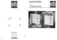
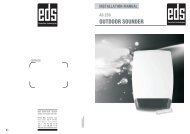
INSTALLATION MANUAL<br />
AS 290<br />
OUTDOOR SOUNDER<br />
SERVICE<br />
8 8<br />
EDS Elektronik Destek<br />
Sanayi ve Ticaret Ltd. Þti.<br />
Meclis Mah. Teraziciler Cad.<br />
Kýlýç Sok. No:4 34785<br />
Sarýgazi/ Ýstanbul<br />
Phone : +90 216 528 45 00<br />
Fax : +90 216 314 17 80<br />
www.eds.com.tr eds@eds.com.tr<br />
KK-AS2 9 0/0703-1<br />
\\Edsfile\Pazarlama\Kullanim kilavuzu\EDS\ INGILIZCE \Harici <strong>Siren</strong> \ AS290_eng.pdf
AS 290<br />
OUTDOOR SOUNDER<br />
AS 290<br />
OUTDOOR SOUNDER<br />
General<br />
AS 290 Series <strong>Outdoor</strong> Sounders are aesthetically designed, high quality sounders for outdoor usage.<br />
These products are compatible <strong>with</strong> all security systems and also durable for any kind of weather<br />
conditions and impact.<br />
Sounders are protected <strong>with</strong> outer plastic material cover and also inner metal cover is optional.<br />
AS 290 Series Sounders are compatible <strong>with</strong> all alarm panels and interior tamper key which is used for the<br />
tamper and system disorders and also running <strong>LED</strong> display is available.<br />
AS 290 Series Sounders are designed for installation <strong>with</strong>out screw so that outer plastic cover montages<br />
together practical and easily.<br />
The piezo buzzer <strong>with</strong> extremely high sound level capacity used for AS 290 series sounders. AS 290 Series<br />
Sounders are controlled by microprocessor.<br />
Warning & Cautions<br />
• Please read the manual before attempting installation or operation.<br />
• Do not keep close a fire to the battery.<br />
• Do not reverse charge.<br />
• Do not short-circuit.<br />
• For the perfect sound performance please keep the surface as smooth as possible.<br />
• When occurs any problem on the sounder, turn off the power immediately and contact the<br />
technical service.<br />
Techinical Specifications<br />
Model<br />
Operating voltage<br />
Stand-by current<br />
Alarm current<br />
Voice output<br />
Voice frequency<br />
Sound type<br />
Starting delay<br />
<strong>Siren</strong> time<br />
Buzzer<br />
Trigger type<br />
Beacons<br />
Stand-by <strong>LED</strong> display<br />
Tamper<br />
Environment<br />
Application<br />
Housing<br />
Colors of housing<br />
Dimensions<br />
Weight<br />
Operating temperature<br />
AS 290<br />
13.6VDC<br />
33mA<br />
290mA<br />
110dB<br />
2.0-3.3Khz<br />
Single<br />
Selectable (5 min.)<br />
5min or 15min selectable<br />
Single Piezo<br />
Negative<br />
Blue or Red<br />
Running <strong>LED</strong><br />
Available<br />
<strong>Outdoor</strong><br />
Alarm Panels<br />
ABS Plastic<br />
White<br />
280x270x70<br />
810gr<br />
-10°C ~ +50°C<br />
Optional Accessory<br />
Battery<br />
Inner cover<br />
Piezo<br />
6V 280mAH NiCd<br />
Galvanized<br />
2. Piezo<br />
2 8 7 8
SAB +12V- S1<br />
SAB +12V- S1<br />
SAB +12V- S1<br />
AS 290 AS 290<br />
OUTDOOR SOUNDER<br />
OUTDOOR SOUNDER<br />
Sample Panel Connections<br />
Mount<br />
Opening The Top Cover Before Mounting<br />
S<br />
0<br />
R<br />
T<br />
S-<br />
S+<br />
A<br />
B<br />
C<br />
D<br />
S<br />
1- Place the sounder on a smooth table. Turn<br />
on two screws to the counter clock wise <strong>with</strong><br />
the number 4 screw driver to open the top<br />
cover as shown Figure 1.<br />
Figure 1<br />
GENEL/CLASSIC/ST8048 VERITAS 8/8R<br />
AC-AC<br />
EARTH<br />
+ BEL<br />
-<br />
DATA<br />
COM<br />
POS<br />
AUX1<br />
510R<br />
CADDX NX 4/6/8 AUX1 programmer:<br />
*897130#<br />
47 #<br />
7*<br />
max.0 - 255dk<br />
*46#1***EXIT<br />
CADDX NX-4/6/8 PREMIER 412/816<br />
(Prg. input)<br />
(Location(Menu) NO)<br />
(Prg. Output options)<br />
(outrput active 0-.255min.)<br />
(Prg. Output)<br />
Figure 9<br />
8<br />
2 STRB<br />
1 SIREN<br />
Aux<br />
INPUT<br />
Z8<br />
Z1<br />
-<br />
AUX<br />
+<br />
ZONE<br />
0V<br />
TAMP<br />
-SRT<br />
- PIEZ<br />
STR<br />
+ PIEZO<br />
-<br />
+ SIREN<br />
17VAC<br />
EARTH<br />
2K2<br />
UNITECH R8<br />
SAB +12V- S1 SAB +12V- S1<br />
2-Place the battery to the slot shown in Figure 2.<br />
Be careful<br />
the polarities and the direction of the<br />
battery for the cable connection. Fix the battery<br />
<strong>with</strong> the cable bound.<br />
3-Mark the screw holes and suspender places<br />
on the wall <strong>with</strong> the aid of box bottom plastic<br />
or template on the package for mounting as<br />
shown Figure 3.<br />
Cable<br />
Entry<br />
Screw<br />
Screw<br />
Battery placement<br />
Figure 2<br />
Suspender<br />
Screw<br />
Screw<br />
Figure 3<br />
6 8<br />
3 8
SAB +12V- S<br />
AS 290 AS 290<br />
OUTDOOR SOUNDER<br />
OUTDOOR SOUNDER<br />
Mount<br />
Mount<br />
Card Placement<br />
4- Before to set the electricity connections of the card as shown in electricity connections Figure 4<br />
take off the JP2 and wait 5 minutes for activating the ‘Starting Delay’ so that during the connection<br />
prevented the unnecessary working possibilities and then complete the electrical connection same<br />
as Figure 4.<br />
After electrical connection during the normal conditions if you do not want ‘Starting Delay’ please<br />
take on the JP2.<br />
FACTORY DEFAULTS<br />
JP 1 :<br />
JP 2:<br />
JP 4:<br />
Function<br />
Supply type<br />
Starting delay<br />
OPEN<br />
OPEN<br />
SHORT<br />
Jumper<br />
JP 1<br />
JP 2<br />
Short<br />
SCB Mode<br />
is not active<br />
-<br />
Open<br />
SCB Mode<br />
is active<br />
5 min.<br />
Tamper<br />
+<br />
12VDC<br />
-<br />
Sounder Trigger<br />
JP4<br />
JP2<br />
Battery<br />
JP1<br />
Buzzer<br />
Mic<br />
ro switch<br />
Attaching the Top Cover<br />
As shown on Figure 7 place the ‘A’ nail as they<br />
would fit into the ‘B’ holes and then press to the<br />
top cover Place the sounder on a smooth table.<br />
Turn off two screws to the clock wise <strong>with</strong> the<br />
number 4 screw driver to close the top cover as<br />
shown Figure 6.<br />
. Opening The Top Cover After Mounting<br />
As shown on Figure 7 push the ‘M’ latch <strong>with</strong> a<br />
straight screw driver to upwards and lift the top<br />
cover. Again push the top cover upwards to let<br />
the ‘A’ nails release and remove the top cover.<br />
Screw<br />
A<br />
B<br />
B<br />
Figure 6<br />
A<br />
Screw<br />
Sounder time<br />
JP 4<br />
5 min.<br />
15 min.<br />
AS 290 sounder works <strong>with</strong> negative trigger. Please adjust<br />
the panel properly. Sample of the connections can see on<br />
Page 6/ Figure 8<br />
SCB Mode: In this mode the unit draws the the majority of<br />
its sounding current from the built-in battery. In this mode<br />
volume is reduced.<br />
Figure 4<br />
Figure 4<br />
Mounting the Metal Cover<br />
Mount optionally provided metal cover as shown<br />
on Figure 8<br />
Figure 7<br />
5- After completing the electricity and battery<br />
connections, place the transparent protection<br />
cover as shown on Figure 5.<br />
Transparent<br />
Protection cover<br />
Important Mounting Notes<br />
Figure 8<br />
Figure 5<br />
1- It should be at least 5 cm below the ceiling in order to be able to open the top cover during assembly.<br />
2- Choose a clean and smooth surface for easy mounting.<br />
3- Use 4 units of M4* 52 metal screw and M8 plastic screw holder in-wall.<br />
4 8 5 8