Memory-based low density parity check code decoder ... - KAIST
Memory-based low density parity check code decoder ... - KAIST
Memory-based low density parity check code decoder ... - KAIST
Create successful ePaper yourself
Turn your PDF publications into a flip-book with our unique Google optimized e-Paper software.
<strong>Memory</strong>-Based Low Density Parity Check Code<br />
De<strong>code</strong>r Architecture Using Loosely Coupled Two Data-F<strong>low</strong>s<br />
Se-Hyeon Kang and In-Cheol Park<br />
Department of Electrical Engineering and Computer Science, <strong>KAIST</strong><br />
373-1 Gusung-Dong Yuseong-Gu, Daejeon 305-701, Republic of Korea<br />
ABSTRACT<br />
To achieve high throughput, parallel decoding of <strong>low</strong> <strong>density</strong><br />
<strong>parity</strong> <strong>check</strong> (LDPC) <strong>code</strong>s is required, but needs a large set of<br />
registers and complex interconnection due to randomly located<br />
1’s in a sparse <strong>parity</strong> <strong>check</strong> matrix of large block size. This paper<br />
proposes a memory-<strong>based</strong> decoding architecture for <strong>low</strong> <strong>density</strong><br />
<strong>parity</strong> <strong>check</strong> <strong>code</strong>s using loosely coupled two data f<strong>low</strong>s. Instead<br />
of register, intermediate values are optimally grouped and<br />
scheduled to store into the segmented memory, which reduces<br />
large area and enables a scalable architecture. The performance<br />
of the proposed de<strong>code</strong>r architecture is demonstrated by<br />
implementing a 1024 bit, rate-1/2 LDPC <strong>code</strong>s de<strong>code</strong>r.<br />
1. INTRODUCTION<br />
Low <strong>density</strong> <strong>parity</strong> <strong>check</strong> (LDPC) <strong>code</strong>s are originally devised to<br />
exploit <strong>low</strong> decoding complexity by constructing a sparse <strong>parity</strong><br />
<strong>check</strong> matrix. Since LDPC <strong>code</strong>words does not have a<br />
maximized minimum distance due to the sparse <strong>parity</strong> <strong>check</strong><br />
matrix, the typical minimum distance increases linearly with the<br />
block length. The error probability decreases exponentially for<br />
sufficiently long block length. Moreover the decoding<br />
complexity is linearly proportional to the <strong>code</strong> length. LDPC<br />
<strong>code</strong>s are applied to various areas such as data storage, digital<br />
subscriber line and CDMA, especially space time <strong>code</strong>d OFDM<br />
systems due to its scalability [6] [7] [8]. Recent simulation<br />
results show that the performance of LDPC <strong>code</strong>s is close to that<br />
of turbo <strong>code</strong>s [2] [3].<br />
Despite of these advantages, LDPC <strong>code</strong>s made little impact<br />
on the information theory community because of the storage<br />
requirements in encoding and the computational demands of<br />
decoding. The Modern VLSI technology enables decoding<br />
architectures to exploit the benefit of inherently parallel<br />
decoding algorithm for LDPC <strong>code</strong>s. Blanksby et al.<br />
implemented a 1-Gb/s fully parallel de<strong>code</strong>r in which the<br />
message passing algorithm is directly mapped [4]. This<br />
architecture, however, requires complex hand-wired routing<br />
between concurrent processing elements corresponding to each<br />
node of the message passing algorithm, leading to the average<br />
net length of 3mm and the total die size of 52.5mm 2 . On the<br />
other side, Yeo et al. proposed an area efficient architecture<br />
which serializes the computations of each row and column by<br />
sharing computation units [5]. Consequently, one iteration in<br />
decoding a <strong>code</strong>word takes 9612 cycles and wide input<br />
multiplexers are required to select one of 18432 intermediate<br />
values to be fed to shared computation units. These two counter<br />
examples show that high throughput LDPC <strong>code</strong>s de<strong>code</strong>r<br />
architecture should exploit the benefit of parallel property of the<br />
decoding algorithm while reducing the interconnection<br />
complexity.<br />
Based on this observation the paper proposes an architecture<br />
that reconstructs the data f<strong>low</strong> of the iterative decoding to<br />
minimize the interconnection. While the previous<br />
implementations iteratively calculate messages that depend on<br />
each other, the proposed architecture separates the data f<strong>low</strong> into<br />
two paths by duplicating the computation units except row and<br />
column summation. Each path calculates one of row and column<br />
summation and completes the whole iteration path by<br />
referencing the summation of the other path. Furthermore, the<br />
messages are stored into segmented memory to reduce the area.<br />
The rest of this paper is organized as fol<strong>low</strong>s. Section 2<br />
summarizes <strong>low</strong> <strong>density</strong> <strong>parity</strong> <strong>check</strong> <strong>code</strong>s and their decoding<br />
algorithm. Section 3 proposes a new architecture for high<br />
throughput LDPC <strong>code</strong>s de<strong>code</strong>r <strong>based</strong> on segmented memory.<br />
An implementation example of the proposed architecture is<br />
presented in Section 4 along with its performance result, and<br />
Section 5 provides some concluding remarks.<br />
2. LOW DENSITY PARITY CHECK CODES<br />
LDPC <strong>code</strong>s which were first introduced by Gallager in 1962 [1]<br />
is defined by a binary linear block <strong>code</strong> of length n and a <strong>parity</strong><br />
<strong>check</strong> matrix H with a column weight and a row weight : (n, ,<br />
). The <strong>parity</strong> <strong>check</strong> matrix H has a total number of n columns<br />
and J rows, where J represents the total number of <strong>parity</strong> <strong>check</strong><br />
equations of the <strong>code</strong>. There are 2 K distinct <strong>code</strong>words, where K<br />
is the message length, K = n – J. The numbers and have to<br />
remain small with respect to n in order to obtain a sparse matrix<br />
H =<br />
column weight = 3<br />
1 1 1 1 0 0 0 0 0 0 0 0 0 0 0 0 0 0 0 0<br />
0 0 0 0 1 1 1 1 0 0 0 0 0 0 0 0 0 0 0 0<br />
0 0 0 0 0 0 0 0 1 1 1 1 0 0 0 0 0 0 0 0<br />
0 0 0 0 0 0 0 0 0 0 0 0 1 1 1 1 0 0 0 0<br />
0 0 0 0 0 0 0 0 0 0 0 0 0 0 0 0 1 1 1 1<br />
1 0 0 0 1 0 0 0 1 0 0 0 1 0 0 0 0 0 0 0<br />
0 1 0 0 0 1 0 0 0 1 0 0 0 0 0 0 1 0 0 0<br />
0 0 1 0 0 0 1 0 0 0 0 0 0 1 0 0 0 1 0 0<br />
0 0 0 1 0 0 0 0 0 0 1 0 0 0 1 0 0 0 1 0<br />
0 0 0 0 0 0 0 1 0 0 0 1 0 0 0 1 0 0 0 1<br />
1 0 0 0 0 1 0 0 0 0 0 1 0 0 0 0 0 1 0 0<br />
0 1 0 0 0 0 1 0 0 0 1 0 0 0 0 1 0 0 0 0<br />
0 0 1 0 0 0 0 1 0 0 0 0 1 0 0 0 0 0 1 0<br />
0 0 0 1 0 0 0 0 1 0 0 0 0 1 0 0 1 0 0 0<br />
0 0 0 0 1 0 0 0 0 1 0 0 0 0 1 0 0 0 0 1<br />
row weight = 4<br />
rows J = 15<br />
columns n = 20<br />
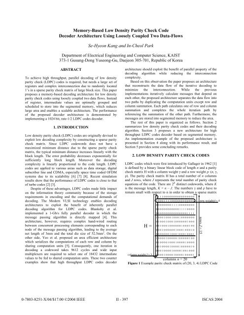
Figure 1 Example <strong>parity</strong> <strong>check</strong> matrix of (20, 3, 4) LDPC Code
H and they have are related to n and J as expressed in the<br />
fol<strong>low</strong>ing equation: n<br />
J . The <strong>code</strong> rate of LDPC<br />
<strong>code</strong>s is defined as R 1 / . Figure 1 shows an example H<br />
matrix of (20, 3, 4) LDPC <strong>code</strong>.<br />
2.1. Motivation<br />
LDPC <strong>code</strong>s are often represented by factor graph inspiring to<br />
understand the message passing decoding algorithm. Figure 2<br />
shows a factor graph for (7,4) Hamming <strong>code</strong>. Direct<br />
implementation of the message passing algorithm, however,<br />
faces with large storage requirement and complex<br />
interconnection because the number of message is twice as many<br />
as the number of edges. There are quite large numbers of edges<br />
since LDPC <strong>code</strong>s generally has large block <strong>code</strong> size. Even<br />
worse, their interconnections are complex and irregular as shown<br />
x 1<br />
variable<br />
message<br />
H =<br />
1 0 0 1 0 1 1<br />
0 1 0 1 1 1 0<br />
0 0 1 0 1 1 1<br />
in the factor graph. The proposed architecture concatenates and<br />
aligns these messages by row or column and stores them in<br />
segmented memories instead of mapping them to registers to<br />
alleviate the storage requirements and complex interconnections.<br />
This is possible because the number of 1’s in a row or column is<br />
small and small number of bits is sufficient to represent a<br />
message.<br />
Employing memory, however, prevents simultaneous<br />
accesses to several elements in it. Therefore messages are<br />
grouped into as many as the number of parallel processing<br />
groups and stored into segmented memories. When grouping, the<br />
dependencies between row and column should be considered to<br />
minimize the processing latency. Detailed techniques on<br />
grouping and corresponding scheduling algorithm are described<br />
in the fol<strong>low</strong>ing section.<br />
2.2. Sum-product decoding algorithm<br />
Unlike the general <strong>parity</strong> <strong>check</strong> <strong>code</strong>s, LDPC <strong>code</strong>s cannot be<br />
de<strong>code</strong>d optimally since it is NP-complete problem. Instead, an<br />
approximate algorithm called iterative probabilistic decoding is<br />
used, which is also known variously as sum-product [11] or<br />
belief propagation [9]. The sum-product algorithm which can be<br />
regarded as a message passing algorithm on a bipartite graph is<br />
described be<strong>low</strong>.<br />
1) Initialize a variable node to the probability ratio of the<br />
corresponding received bit.<br />
pr (<br />
j<br />
| xj<br />
1)<br />
<br />
j<br />
<br />
Pr ( | x 1)<br />
j<br />
j<br />
2) Horizontal step: Compute the likelihood ratio corresponding<br />
to outgoing messages of variable nodes and propagate to <strong>check</strong><br />
nodes.<br />
1ij<br />
'<br />
ij<br />
<br />
1+ <br />
j' N( i)\ j ij'<br />
x 2<br />
x 3<br />
x 4<br />
x 5<br />
x 6<br />
x 7<br />
s 1<br />
s 2<br />
s 3<br />
<strong>check</strong><br />
message<br />
S 1<br />
= x 1<br />
+ x 4<br />
+ x 6<br />
+ x 7<br />
S 2<br />
= x 2<br />
+ x 4<br />
+ x 5<br />
+ x 6<br />
S 3<br />
= x 3<br />
+ x 5<br />
+ x 6<br />
+ x 7<br />
Figure 2 Factor graph for (7, 4) Hamming <strong>code</strong><br />
3) Vertical step: From the variable messages, compute<br />
probability ratio corresponding to the outgoing <strong>check</strong> messages<br />
and propagate to variable nodes.<br />
pr (<br />
j<br />
| xj 1) 1i'<br />
j<br />
ij<br />
<br />
Pr (<br />
j<br />
| xj 1) i' M( j)\ i1i'<br />
j<br />
4) Create a tentative bit-by-bit decoding xi using pseudoposteriori<br />
probability.<br />
pr (<br />
j<br />
| xj 1) 1ij<br />
<br />
j<br />
<br />
Pr (<br />
j<br />
| xj 1) iM( j)<br />
1ij<br />
5) Check if x·H T = 0 is satisfied.<br />
6) If the condition in step 5) is satisfied, the decoding algorithm<br />
finishes. Otherwise the algorithm repeats from the step 2).<br />
The symbols, and , represent the outgoing messages of<br />
the <strong>check</strong> and the variable nodes, respectively, and N(i) , M(j)<br />
represent the set of neighbor nodes connected by edges of <strong>check</strong><br />
node i and variable node j, respectively. The not-notation (’)<br />
which is marked as subscript in the indexes means that the<br />
product is calculated over the indexes excluding its own index.<br />
Detailed explanation of the algorithm including the equations<br />
can be found in [13]. To reduce the hardware cost, the products<br />
in the equations of the above algorithm description are usually<br />
transformed into summation by using log-likelihood probability.<br />
Therefore the resulting equations are as fol<strong>low</strong>s and the proposed<br />
architecture constructs two paths of data f<strong>low</strong> by combining<br />
these equations. When posteriori probability is translated in log<br />
domain, it becomes robust and can be represented in fixed point<br />
numbers with small number of bits while maintaining coding<br />
gain. It contributes area-efficient implementation.<br />
ij<br />
'<br />
ij<br />
log(tanh( ) : horizontal step<br />
j' N( i)\<br />
j<br />
2<br />
pr (<br />
j<br />
| xj<br />
1)<br />
1<br />
ij<br />
log( ) 2 tanh (exp( i'<br />
j<br />
)) : vertical step<br />
pr ( | x 1)<br />
j<br />
j<br />
i' M( j)\<br />
i<br />
3. PROPOSED LDPC DECODER ARCHITECTURE<br />
Since the functions of variable nodes and <strong>check</strong> nodes are simple,<br />
the main problem in the implementation is how to pass the large<br />
number of messages to other nodes. In the previous<br />
implementations, the problem is solved by providing complex<br />
interconnections. To tackle this problem, this paper proposes an<br />
architecture <strong>based</strong> on segmented memory to reduce overall area<br />
and enable high throughput decoding.<br />
3.1. Loosely coupled two data f<strong>low</strong>s<br />
As shown in the Figure 3 (a), the previous data f<strong>low</strong> base on the<br />
message passing decoding generates considerable amount of<br />
messages from variable nodes to <strong>check</strong> nodes and vice versa<br />
which results in complex interconnection. Since ’s in the same<br />
row are summed up to calculate their neighbor ’s located at<br />
different columns and vice versa. Therefore complex<br />
interconnection cannot be avoided if the messages themselves<br />
are passed between nodes. The close look at the iterative<br />
decoding algorithm, however, tells that vertical and horizontal<br />
steps can be broken down to the summation of all the elements in<br />
the same row or column and subtraction of its own value from<br />
the summation. From this observation, this paper proposes an<br />
architecture which has two separate data f<strong>low</strong> by duplicating the<br />
processing elements except the summation.
(a)<br />
<br />
ij<br />
messages<br />
In fact, complex interconnection is required to sum up the<br />
intermediate values in the same row or column which are aligned<br />
in the other way. To resolve this problem each data f<strong>low</strong><br />
calculates only one of row and column summation value and<br />
passed it to other data f<strong>low</strong>. Since each data f<strong>low</strong> has the whole<br />
processing elements, the computation units for and memory<br />
calculate row and column summation respectively and simply<br />
these values, not the all messages, are fed into the other to<br />
construction complete iteration path. Therefore the resulting<br />
intermediate values can be written back to the same memory<br />
address where they are read for the next iteration. Thus index<br />
generation for writing results to each other’s path is no longer<br />
necessary. This duplicated data f<strong>low</strong> is shown in the Figure 3 (b).<br />
As the whole row and columns are not processed simultaneously,<br />
duplicating processing units is not significant overhead.<br />
Precisely speaking, the intermediate values in the and <br />
memory is now no longer and define in the subsection 2.2.<br />
3.2. Quantization and segmentation<br />
Due to the inherent robustness of Log-likelihood Ratio, and <br />
can be quantized into small number of bits. According to our<br />
experiment on the quantization effect against the number of bits<br />
in both integer and fractional parts, fractional part should be<br />
more emphasized than integer part and 5 bits which consists of 2<br />
bit for integer part and 3 bits for fractional part are sufficient<br />
enough to express the and . Therefore and in the same<br />
row or column can be concatenated into one word and each row<br />
or column operation is enabled by just one memory read/write.<br />
In addition, and memory is segmented to remove wasted<br />
cycles due to memory read and write. In other words, memory<br />
read and write at a row or a column occur while another row or<br />
column is used to calculate the summation value in the<br />
processing unit. Rows and columns which will be processed in<br />
parallel to achieve high throughput are also stored in different<br />
segments of memory.<br />
3.3. Scheduling of , calculations<br />
<br />
messages<br />
ij<br />
ij<br />
: log(tanh(x)) : atanh(exp(x))<br />
Figure 3 (a) Previous data f<strong>low</strong> (b) Duplicated data f<strong>low</strong><br />
(b)<br />
If the intermediate values are grouped and stored into the<br />
segmented memory as described in the subsection 3.2, how the<br />
rows and columns are grouped and scheduled should be<br />
determined first. Since there are dependencies between each<br />
rows and columns, to find an optimum schedule that minimize<br />
latency due to the dependencies takes considerable amount of<br />
time. There may be heuristic algorithms and the authors propose<br />
an algorithm that reduces required rows and determine their<br />
order <strong>based</strong> on the given number of column groups are described<br />
be<strong>low</strong>:<br />
1) Make n group of columns which have common rows as<br />
many as possible.<br />
<br />
ij<br />
i<br />
<br />
j<br />
ij<br />
<br />
ij<br />
2) Extract exclusive row list that is required to each column<br />
group<br />
3) Sort each column group by the number of required rows<br />
4) Put the group which requires smallest number of rows into a<br />
sequence.<br />
5) Remove the rows of the just inserted column groups from<br />
the other column groups.<br />
6) If the ordering is completed, the algorithm halts. Otherwise<br />
repeats from step 3).<br />
Though the ordering can be determined for a given number<br />
of groups, the problem of how many columns are grouped into a<br />
group still remains. The number of groups can be determined<br />
after ordering for several numbers of groups are generated. For<br />
each case maximum required number of rows are varies not<br />
linearly proportional to number of groups, while the processing<br />
cycles are linearly proportional. Therefore some trade-offs can<br />
be done between area and processing time. Figure 4 shows some<br />
experimental result of ordering for several numbers of groups.<br />
The bar in the graph represents maximum number of rows which<br />
corresponds the hardware cost and total cycles for one iteration.<br />
The break line represents the product of these two values as a<br />
measure of trade-off between throughput and hardware cost.<br />
140<br />
120<br />
100<br />
80<br />
60<br />
40<br />
20<br />
0<br />
max. rows total cycles product<br />
Hardware cost<br />
8 cols 16 cols 32 cols 64 cols<br />
number of columns<br />
2500<br />
2000<br />
1500<br />
1000<br />
Figure 4 Processing time vs. hardware cost<br />
4. IMPLEMENTATION AND PERFORMANCE<br />
We design a (1024, 3, 6) LDPC <strong>code</strong> de<strong>code</strong>r using the proposed<br />
architecture. The block diagram of our implementation is plotted<br />
in Figure 5. The overall architecture is divided into two paths<br />
according to and memory. In each path there are processing<br />
elements which consists of lookup tables for the functions,<br />
log(tanh(x)) and atanh(exp(x)), and adders. Calculated ’s and<br />
’s in each iteration are grouped and stored in corresponding<br />
segmented memory for parallel computation. And there is array<br />
of D flip-flops for instant and simultaneous access of row and<br />
column summation values. Multiplexers feed them to<br />
corresponding processing elements at the other side. Since ’s<br />
and ’s are stored in segmented memory in optimally scheduled<br />
sequence, processing elements can read and write the<br />
intermediate values to calculate the summation by simply<br />
incrementing the address of segmented memory. Complete data<br />
f<strong>low</strong> of sum-product algorithm excluding row or column<br />
summation respectively consists an iteration of and <br />
computation. Column summation values are bit-by-bit de<strong>code</strong>d<br />
according to their sign bits and become final output.<br />
The performance of the proposed architecture with 64<br />
parallel processing for (1024, 3, 6) LDPC <strong>code</strong>s is summarized<br />
in Table 1. Bit rate is comparable to the fully parallel<br />
architecture implemented by Blanksby et al., but significant area<br />
reduction is achieved. While the number of iterations is<br />
determined to 64 from the architecture of Blanksby’s<br />
500<br />
0
implementation, there is no restriction in the proposed<br />
architecture and thus we can choose 8 iterations. Most of the area<br />
of the proposed architecture is occupied by the and memory,<br />
and this fact proves that the duplicating the processing elements<br />
is a little overhead. The case when the intermediate values are<br />
store in the D F/F’s instead of segmented memory is also shown<br />
in the Table 1. This improves bit rate a little by removing a few<br />
cycle of memory read/write latencies but the area overhead is<br />
considerable.<br />
Table 1 Performance summary<br />
Blanksby [9] Segmented <strong>Memory</strong> D F/F<br />
Technology 0.16 um 0.25 um 0.25 um<br />
Bit rate 1 Gbps 853 Mbps 960 Mbps<br />
52.5 mm 2 4.75 mm 2 8.71 mm 2<br />
Other: 1.78 mm 2 2.59 mm 2<br />
Area<br />
MEM: 3.05 mm 2 6.12 mm 2<br />
5. CONCLUSION<br />
Large storage elements and complex interconnection are the<br />
main obstacles in VLSI implementation of the LDPC <strong>code</strong>s<br />
de<strong>code</strong>rs while their decoding complexity is relatively <strong>low</strong>. This<br />
paper has proposed a memory segmentation technique and a<br />
corresponding scheduling algorithm for memory-<strong>based</strong> LDPC<br />
<strong>code</strong>s decoding architecture. Compared to the fully parallel<br />
architecture, the proposed architecture saves the overall area<br />
significantly and simplifies interconnection by storing<br />
intermediate values ( and ) into segmented memory<br />
associated with rows and columns. Since the overall structure of<br />
the proposed architecture is highly regular, it is easy to scale up<br />
and down the parallelism considering a given design constraints.<br />
6. ACKNOWLEDGEMENT<br />
Figure 5 Block diagram of the proposed architecture<br />
This work was supported by Institute of Information Technology<br />
Assessment through the ITRC, by the Korea Science and<br />
Engineering Foundation through MICROS center and by IC<br />
Design Education Center (IDEC).<br />
7. REFERENCES<br />
[1] R. G. Gallager, “Low <strong>density</strong> <strong>parity</strong> <strong>check</strong> <strong>code</strong>s,” IRE Trans.<br />
Info. Theory, pp. 533-547, Jan. 1962.<br />
[2] D. J. C. Mackay, “Good error-correcting <strong>code</strong>s <strong>based</strong> on very<br />
sparse matrices,” IEEE Trans. Info. Theory, pp. 399-431,<br />
Mar. 1999.<br />
[3] S. Chung, D. Forney, T. Richardson, and R. Urbanke, “On<br />
the design of <strong>low</strong>-<strong>density</strong> <strong>parity</strong>-<strong>check</strong> <strong>code</strong>s within 0.0045<br />
db of the Shannon limit,” IEEE Comm. Letters, pp. 58-60,<br />
Feb. 2001.<br />
[4] Andrew J. Blanksby and Chris J. Howland, “A 690-mW 1-<br />
Gb/s, Rate-1/2 <strong>low</strong>-<strong>density</strong> <strong>parity</strong>-<strong>check</strong> <strong>code</strong> de<strong>code</strong>r,”<br />
IEEE J. of Solid-State Circuits, pp. 404-412, Mar. 2002.<br />
[5] Engling Yeo, Payam Pakzad, Borivoje Nikoli and Venkat<br />
Anantharam, “VLSI Architectures for Iterative De<strong>code</strong>rs in<br />
Magnetic Recording Channels,” IEEE Trans. Magnetics, pp.<br />
748-755, Mar. 2001.<br />
[6] E. Eleftheriou and S. Ölçer, “Low-<strong>density</strong> <strong>parity</strong>-<strong>check</strong> <strong>code</strong>s<br />
for digital subscriber lines,” IEEE International Conference<br />
on Communications, pp. 1752-1757, May 2002.<br />
[7] Vladislav Sorokine, Frank R. Kschischang and Subbarayan<br />
Pasupathy, “Gallager <strong>code</strong>s for CDMA applications – Part I:<br />
Generalizations, constructions and performance bounds,”<br />
IEEE Trans. Communications, pp. 1660-1668, Oct. 2000.<br />
[8] Ben Lu, Xiaodong Wang and Krishna R. Narayanan, “LDPC<strong>based</strong><br />
space-time <strong>code</strong>d OFDM systems over correlated<br />
fading channels: Performance analysis and receiver design,”<br />
IEEE Trans. Communications, pp. 74-88, Jan. 2002.<br />
[9] J. Pearl, Probabilistic Reasoning in Intelligent Systems:<br />
Networks of Plausible Inference, Morgan Kaufmann, 1988.<br />
[10] Ka Leong, Lo, Layered Space Time Structures with Low<br />
Density Parity Check and Convolutional Codes, MS Thesis,<br />
School of EIE, Univ. of Sydney, 2001.<br />
[11] N. Wiberg, Codes and Decoding on General Graphs, PhD<br />
thesis, Dept. of EE, Linköping Univ. Sweden, 1996


