
You also want an ePaper? Increase the reach of your titles
YUMPU automatically turns print PDFs into web optimized ePapers that Google loves.
T.O. 1-1-4<br />
TECHNICAL MANUAL<br />
EXTERIOR FINISHES, INSIGNIA AND<br />
MARKINGS,<br />
APPLICABLE TO USAF AIRCRAFT<br />
F09603-89-3074<br />
(ATOS)<br />
DISTRIBUTION STATEMENT - Approved for public release; distribution is unlimited. Other request for this<br />
document should be referred to WR-ALC/LKC, Robins AFB GA 31098. Questions concerning technical content<br />
should be referred to WR-ALC/LKJTC, Robins AFB GA 31098.<br />
Published under authority of the Secretary of the Air Force<br />
14 MAY 1994<br />
CHANGE 6 - 20 MARCH 1998
TO 1-1-4<br />
LIST OF EFFECTIVE PAGES<br />
NOTE:<br />
INSERT LATEST CHANGED PAGES. DESTROY SUPERSEDED PAGES.<br />
The portion of the text affected by the changes is indicated by a vertical line in the outer margins<br />
of the page. Changes to illustrations are indicated by miniature pointing hands. Changes to wiring<br />
diagrams are indicated by shaded areas.<br />
Dates of issue for original and changed pages are:<br />
Original ........................... 0................ 14 May 1994 Change............................. 5............29 August 1997<br />
Change............................. 1......15 September 1995 Change............................. 6............. 20 March 1998<br />
Change............................. 2............9 January 1996<br />
Change............................. 3......20 September 1996<br />
Change............................. 4..........31 January 1997<br />
TOTAL NUMBER OF PAGES IN THIS PUBLICATION IS 176, CONSISTING OF THE FOLLOWING:<br />
Page *Change Page *Change Page *Change<br />
No. No. No. No. No. No.<br />
Title ......................................... 6<br />
A .............................................. 6<br />
i - v...........................................0<br />
vi Blank ...................................0<br />
1-1 ............................................0<br />
1-2 ........................................... 6<br />
1-3 - 1-4 ...................................0<br />
2-1 - 2-4 ...................................0<br />
3-1 - 3-3 ...................................0<br />
3-4 Blank.................................0<br />
4-1 ............................................0<br />
4-2 ............................................3<br />
4-3 - 4-4 ...................................0<br />
4-5 - 4-6 ...................................5<br />
5-1 - 5-4 ...................................0<br />
6-1 - 6-2 ...................................0<br />
6-3 - 6-4 ...................................5<br />
6-5 ............................................0<br />
6-6 Blank.................................0<br />
7-1 - 7-2 ...................................0<br />
A-1 - A-2 ..................................0<br />
A-3 - A-4 ..................................3<br />
A-5 - A-6 ..................................0<br />
A-7............................................4<br />
A-8............................................0<br />
B-1 - B-12 ................................0<br />
B-13......................................... 6<br />
B-14 - B-45 ..............................0<br />
B-46 - B-48 ..............................1<br />
C-1 - C-2 ..................................0<br />
C-3............................................3<br />
C-4 - C-6 ..................................0<br />
D-1 - D-42................................0<br />
D-43......................................... 6<br />
D-44 - D-56..............................0<br />
E-1 - E-8 ..................................0<br />
E-9............................................2<br />
E-10..........................................0<br />
F-1 - F-9...................................0<br />
F-10 Blank ..............................0<br />
*Zero in this column indicates an original page<br />
A Change 6 USAF
T.O. 1-1-4<br />
TABLE OF CONTENTS<br />
Section/Para<br />
Page<br />
I GENERAL ....................................................................................................................................... 1-1<br />
1-1 Purpose......................................................................................................................... 1-1<br />
1-2 Definitions ................................................................................................................... 1-1<br />
1-3 Applicability................................................................................................................. 1-1<br />
1-4 Responsibilities............................................................................................................ 1-1<br />
1-5 Major Command Regulations ..................................................................................... 1-2<br />
1-6 Authorized Deviations................................................................................................. 1-2<br />
1-7 Aircraft Received From Other Services..................................................................... 1-2<br />
1-8 Request for Waivers .................................................................................................... 1-3<br />
1-9 Service Tests ................................................................................................................ 1-3<br />
1-10 Reporting Painting and Marking Deficiencies.......................................................... 1-3<br />
1-11 Decalcomania (Decals) ................................................................................................ 1-3<br />
1-12 Applicable References ................................................................................................. 1-3<br />
<strong>II</strong> STANDARD EXTERIOR FINISHES FOR USAF AIRCRAFT.................................................... 2-1<br />
2-1 Metal Exterior Finishes .............................................................................................. 2-1<br />
2-2 Policy Guidance ........................................................................................................... 2-1<br />
2-3 Air Force Standard Exterior Finishes ....................................................................... 2-3<br />
2-4 Exterior Finish Identification Codes ......................................................................... 2-3<br />
2-5 Special Purpose Exterior Solar Resistant Finishes .................................................. 2-3<br />
2-6 Exhaust, Gun And Rocket Gas/Blast Areas .............................................................. 2-4<br />
2-7 Thermal Ref lective Finish.......................................................................................... 2-4<br />
2-8 Salt Water, Salt Air And Polluted Air....................................................................... 2-4<br />
2-9 Anti-Glare Finishes ..................................................................................................... 2-4<br />
2-10 Acid Resistant Finishes .............................................................................................. 2-4<br />
2-11 Finishes For Aircraft Propellers And Helicopter Rotors.......................................... 2-4<br />
2-12 Anti-Skid Coating For Walkways .............................................................................. 2-4<br />
2-13 Finish System For Engine Air Intake Ducts/Scoops ................................................ 2-4<br />
<strong>II</strong>I STANDARD MARKINGS AND INSIGNIA FOR USAF AIRCRAFT ......................................... 3-1<br />
3-1 General......................................................................................................................... 3-1<br />
3-2 USAF Standard Markings And Insignia ................................................................... 3-1<br />
3-3 General Specification for Lettering and Numerals Used in Marking for<br />
Aircraft......................................................................................................................3-2<br />
3-4 Paint Facility/Finish Identification Block................................................................. 3-2<br />
IV SPECIAL PURPOSE MARKING FOR USAF AIRCRAFT.......................................................... 4-1<br />
4-1 General......................................................................................................................... 4-1<br />
4-2 American Flag Markings ............................................................................................ 4-1<br />
4-3 United States of America Marking ............................................................................ 4-1<br />
4-4 Organization Insignia or Emblems ............................................................................ 4-2<br />
4-5 Outstanding Unit Award Markings........................................................................... 4-2<br />
4-6 Crew Markings ............................................................................................................ 4-2<br />
4-7 Local Station Numbers and Markings for Aircraft .................................................. 4-2<br />
4-8 Air National Guard (Ang) Aircraft ............................................................................ 4-3<br />
4-9 Usaf Aircraft Supplied Under Map ........................................................................... 4-3<br />
4-10 Aircraft Propeller Markings ....................................................................................... 4-3<br />
4-11 Helicopter Rotor Blade Markings .............................................................................. 4-4<br />
4-12 Tail Rotor Blade Markings ......................................................................................... 4-4<br />
4-13 Installation Of Placards In Aircraft .......................................................................... 4-4<br />
4-14 Identification Markings For Jettisonable Aircraft Components ............................. 4-4<br />
i
T.O. 1-1-4<br />
TABLE OF CONTENTS - Continued<br />
Section/Para<br />
Page<br />
4-15 Marking Of Emergency Lighting (Flashlight) - Cargo And Transport<br />
Type Aircraft ............................................................................................................4-5<br />
4-16 Marking For Walkways And Honeycomb Panels ..................................................... 4-5<br />
4-17 Markings For Drones .................................................................................................. 4-5<br />
4-18 Markings for Search and Rescue Aircraft................................................................. 4-5<br />
4-19 Aircraft Conspicuity and Arctic Markings ................................................................ 4-5<br />
4-20 Establishing New Requirements for Insignia and Markings .................................. 4-6<br />
V STANDARD MARKINGS, FINISHES, AND INSIGNIA FOR CAMOUFLAGED<br />
USAF AIRCRAFT ........................................................................................................................... 5-1<br />
5-1 Purpose of Camouf lage............................................................................................... 5-1<br />
5-2 Camouf lage Authority ................................................................................................ 5-1<br />
5-3 Aircraft Camouf lage Materials.................................................................................. 5-1<br />
5-4 Camouf lage Patterns .................................................................................................. 5-1<br />
5-5 Insignia and Markings................................................................................................ 5-2<br />
5-6 Instructional Markings ............................................................................................... 5-3<br />
5-7 Squadron and Organizational Markings ................................................................... 5-3<br />
5-8 Armament Loads Placard ........................................................................................... 5-3<br />
5-9 Distinctive Unit Aircraft Identification Markings ................................................... 5-3<br />
5-10 Special Operating Force (SOF) Aircraft .................................................................... 5-3<br />
5-11 Nato Markings Code Numbers................................................................................... 5-4<br />
VI SERVICING, GROUND HANDLING, EMERGENCY AND HAZARD WARNING<br />
MARKINGS, (NON-CAMOUFLAGED) AIRCRAFT .................................................................... 6-1<br />
6-1 General......................................................................................................................... 6-1<br />
6-2 Nato Marking Code Numbers .................................................................................... 6-1<br />
6-3 Hydraulic Systems And Landing Gear/Struts .......................................................... 6-1<br />
6-4 Aircraft Grounding Points.......................................................................................... 6-1<br />
6-5 Storage Batteries......................................................................................................... 6-1<br />
6-6 Ejection Seats .............................................................................................................. 6-2<br />
6-7 Identification Of Ballistic Hose Or Tubing Assemblies ........................................... 6-2<br />
6-8 Canopy Removers ........................................................................................................ 6-2<br />
6-9 Marking For Electrical Connections .......................................................................... 6-2<br />
6-10 Markings For Engine Removal .................................................................................. 6-2<br />
6-11 Markings For Tanks And Tankfiller Areas .............................................................. 6-2<br />
6-12 Marking For Engine Compartment Fire Access Panel ............................................ 6-2<br />
6-13 Helicopter Tail Rotor Warning Sign .......................................................................... 6-2<br />
6-14 Propeller Warning Stripes And Signs........................................................................ 6-2<br />
6-15 Removable Escape Panels........................................................................................... 6-3<br />
6-16 Markings For Forced Emergency Entry Or Exit ...................................................... 6-4<br />
6-17 Special Markings For Normal/Emergency External Canopy Release Accesses<br />
On Jet Aircraft..............................................................................................6-4<br />
6-18 Armament Loads Placard ........................................................................................... 6-4<br />
6-19 Instrument Static Opening Markings........................................................................ 6-5<br />
V<strong>II</strong> IDENTIFICATION OF TUBES, HOSE AND PIPE LINES FOR AIRCRAFT .......................... 7-1<br />
7-1 General......................................................................................................................... 7-1<br />
7-2 General Classification of Lines .................................................................................. 7-1<br />
7-3 General Marking of Lines........................................................................................... 7-1<br />
7-4 Method used for Identification of Lines .................................................................... 7-1<br />
7-5 Electrical Conduits ...................................................................................................... 7-2<br />
ii
T.O. 1-1-4<br />
TABLE OF CONTENTS - Continued<br />
Section/Para<br />
Page<br />
A<br />
B<br />
C<br />
D<br />
E<br />
F<br />
7-6 Flexible Cables ............................................................................................................ 7-2<br />
7-7 Air Conditioning Ducts ............................................................................................... 7-2<br />
STANDARD AIR FORCE AIRCRAFT MARKINGS ....................................................................A-1<br />
A-1 National Star Insignia ................................................................................................A-3<br />
A-2 U.S. Air Force Marking...............................................................................................A-3<br />
USAF AIRCRAFT FINISH AND MARKING SPECIFICATIONS AND<br />
ILLUSTRATIONS...........................................................................................................................B-1<br />
SPECIAL PURPOSE AIRCRAFT MARKINGS............................................................................C-1<br />
SPECIFICATIONS - CAMOUFLAGE PATTERNS AND MARKINGS FOR USAF<br />
AIRCRAFT ......................................................................................................................................D-1<br />
SERVICING, GROUND HANDLING, EMERGENCY, HAZARD WARNING MARK-<br />
INGS AND ARMAMENT PLACARD LOCATIONS FOR AIRCRAFT .......................................E-1<br />
IDENTIFICATION CODES AND MARKINGS FOR TUBING, HOSE AND PIPE<br />
FOR AIRCRAFT..............................................................................................................................F-1<br />
iii
T.O. 1-1-4<br />
LIST OF ILLUSTRATIONS<br />
Figure Title Page<br />
A-1 National Star Insignia.............................................................................................................A-4<br />
A-2 National Star Insignia on Swept Wings. ...............................................................................A-5<br />
A-3 U.S. AIR FORCE, USAF and Aircraft Model Designation Serial Number, and<br />
Fuel Requirement ................................................................................................................ A-6<br />
A-4 Form of Letters and Numerals ...............................................................................................A-7<br />
A-5 Typical Marking For Paint Facility/Finish Identification Block .........................................A-8<br />
B-1 B-52 Aircraft Marking Specification......................................................................................B-5<br />
B-2 C-5 Aircraft Marking Specification........................................................................................B-7<br />
B-3 C-9 Aircraft Marking Specifications ......................................................................................B-9<br />
B-4 C-12 Aircraft Marking Specifications ..................................................................................B-12<br />
B-5 C-130 Aircraft Marking Specification..................................................................................B-15<br />
B-6 C-135 Aircraft Marking Specification..................................................................................B-17<br />
B-7 C-141 Aircraft Marking Specification..................................................................................B-19<br />
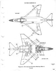
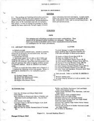
B-8 F-4 Aircraft Marking Specification ......................................................................................B-21<br />
B-9 F-106 Aircraft Marking Specification ..................................................................................B-23<br />
B-10 H-1 Aircraft Marking Specification .....................................................................................B-25<br />
B-11 H-3 Aircraft Marking Specification .....................................................................................B-27<br />
B-12 H-3B Aircraft Marking Specification...................................................................................B-29<br />
B-13 H-53 Aircraft Marking Specification ...................................................................................B-31<br />
B-14 OV-10 Aircraft Marking Specification (FAC Configuration) .............................................B-33<br />
B-15 T-1A Aircraft Marking Specification ...................................................................................B-35<br />
B-16 T-33 Aircraft Marking Specification ....................................................................................B-37<br />
B-17 T-37 Aircraft Marking Specification ....................................................................................B-39<br />
B-18 T-38 Aircraft Marking Specification ....................................................................................B-41<br />
B-19 T-39 Aircraft Marking Specification ....................................................................................B-43<br />
B-20 T-39 All White Aircraft Marking Specification...................................................................B-45<br />
B-21 T-43A Aircraft Marking Specification .................................................................................B-47<br />
C-1 U. S. Flag Marking ..................................................................................................................C-3<br />
C-2 RC-130 Aircraft Conspicuity Marking ...................................................................................C-4<br />
C-3 C-140 Aircraft Conspicuity Marking......................................................................................C-5<br />
C-4 T-39 Aircraft Conspicuity Marking ........................................................................................C-6<br />
D-1 A-7 Aircraft Camouf lage Pattern ..........................................................................................D-3<br />
D-2 ANG A-7 Aircraft Camouf lage Pattern ................................................................................D-5<br />
D-3 B-52 Aircraft Camouf lage Pattern.........................................................................................D-7<br />
D-4 B-52 Aircraft SEA Camouf lage Pattern ................................................................................D-8<br />
D-5 C-5 Aircraft European I Camouf lage Pattern.......................................................................D-9<br />
D-6 C-130 Aircraft Camouf lage Pattern.....................................................................................D-10<br />
D-7 C-130 Aircraft Camouf lage Pattern, European I................................................................D-11<br />
D-8 C-130 Aircraft Camouf lage Pattern For Asia Minor..........................................................D-12<br />
D-9 AC-130 Exterior Finish and Markings, Special Project......................................................D-13<br />
D-10 C-141A European I Camouf lage Pattern.............................................................................D-14<br />
D-11 C-141B Aircraft Camouf lage Pattern, European I .............................................................D-15<br />
D-12 F/RF-4 Aircraft Wraparound Camouf lage Exterior Paint Pattern ...................................D-16<br />
D-13 F-5 Aircraft Camouf lage Pattern.........................................................................................D-17<br />
D-14 F-5 Aircraft Camouf lage Pattern For Asia Minor ..............................................................D-18<br />
D-15 F-111 A/D/E/F Aircraft Camouf lage Pattern ......................................................................D-19<br />
D-16 FB-111A Aircraft Camouf lage Pattern................................................................................D-20<br />
D-17 H-1F/D/N/H Aircraft Standard Camouf lage Pattern .........................................................D-21<br />
D-18 UH-1F/D/N/H Aircraft Camouf lage Pattern .......................................................................D-22<br />
D-19 UH-1F/D/N/H Aircraft European I Camouf lage Pattern ...................................................D-23<br />
D-20 UH-1N Aircraft ‘‘Leopard’’ Camouf lage Pattern.................................................................D-24<br />
iv
T.O. 1-1-4<br />
LIST OF ILLUSTRATIONS - Continued<br />
Figure Title Page<br />
D-21 H-3 Aircraft Camouf lage Pattern ........................................................................................D-25<br />
D-22 CH-3 Aircraft Camouf lage Pattern......................................................................................D-26<br />
D-23 CH-3 Aircraft European I Camouf lage Pattern..................................................................D-27<br />
D-24 H-53 Aircraft Standard Camouf lage Pattern......................................................................D-28<br />
D-25 H-53 Aircraft European I Camouf lage Pattern ..................................................................D-29<br />
D-26 HH-53B Helicopter Camouf lage Pattern.............................................................................D-30<br />
D-27 OV-10 Aircraft Europe I Camouf lage Pattern ...................................................................D-31<br />
D-28 A-37/OA-37 Aircraft Standard Camouf lage Pattern ..........................................................D-33<br />
D-29 AT-38B Aircraft Camouf lage Pattern .................................................................................D-34<br />
D-30 T-39 Aircraft Camouf lage Pattern.......................................................................................D-37<br />
D-31 F/TF-15 Aircraft Camouf lage Pattern for Air Superior Blue ............................................D-38<br />
D-32 F/TF-15 Aircraft Camouf lage Pattern for High and Low Ref lectance Gray ...................D-39<br />
D-33 A-10 Aircraft Camouf lage Patten ″European I″ ................................................................D-41<br />
D-34 A-10 Aircraft Camouf lage Pattern for High and Low Ref lectance Gray ........................D-43<br />
D-35 Typical Distinctive Unit Aircraft Identification Markings ................................................D-47<br />
D-36 Typical Distinctive Unit Aircraft Identification, 24″ Letter Sizes ....................................D-48<br />
D-37 Typical Distinctive Unit Aircraft Identification, 36″ Letter Sizes ....................................D-49<br />
D-38 Typical Distinctive Aircraft Serial Number, 15″ Size.........................................................D-50<br />
D-39 Distinctive Unit and Serial Number Sizes C-130 Aircraft.................................................D-51<br />
D-40 Distinctive Unit and Serial Number Sizes UH-1F Aircraft ...............................................D-52<br />
D-41 Distinctive Unit and Serial Number Sizes F/RF-4 Aircraft ...............................................D-53<br />
D-42 Distinctive Unit and Serial Number Sizes F/TF-15 Aircraft .............................................D-54<br />
D-43 Distinctive Unit and Serial Number Sizes F-16 Aircraft ...................................................D-55<br />
D-44 Distinctive Unit and Serial Number Sizes A-10 Aircraft...................................................D-56<br />
E-1 Typical Symbol Dimensioning.................................................................................................E-2<br />
E-2 Aircraft Markings, Servicing and Precautioning .................................................................E-3<br />
E-3 Decalcomania - Ground Here, International Symbol............................................................E-5<br />
E-4 Markings For Fire Access Panel.............................................................................................E-5<br />
E-5 Helicopter Tail Boom Markings..............................................................................................E-6<br />
E-6 Emergency Instruction Markings ...........................................................................................E-6<br />
E-7 Emergency Entry Markings....................................................................................................E-7<br />
E-8 Armament Placard Marking ...................................................................................................E-8<br />
E-9 Armament Placard Locations..................................................................................................E-9<br />
E-10 Propeller Warning Stripes and Signs...................................................................................E-10<br />
F-1 Examples of Identification Groups.........................................................................................F-5<br />
F-2 Color-coded Functional Identification Tapes ( Sheet 1 of 2) ................................................F-6<br />
F-3 Warning Symbols.....................................................................................................................F-7<br />
F-4 Optional Arrangement for Identification...............................................................................F-8<br />
F-5 Examples of Electrical Identification.....................................................................................F-9<br />
F-6 Tag Identification ....................................................................................................................F-9<br />
LIST OF TABLES<br />
Number Title Page<br />
D-1 Distinctive Unit Markings, Sizes, and Locations, Camouf lage Aircraft...........................D-45<br />
F-1 Functions and Associated Symbols ........................................................................................F-4<br />
v/(vi blank)
TO 1-1-4<br />
SECTION I<br />
GENERAL<br />
1-1. PURPOSE. The purpose of this technical patterns used are generally determined by the geoorder<br />
is to standardize the painting and marking graphical region of the world in which aircraft are<br />
configuration of exterior surfaces of all Air Force to operate and/or the operational role of the airaircraft.<br />
In the event of conf lict between a spe- craft. This term does not include any of the markcific<br />
system/equipment Technical Order (TO) and ings or insignia usually applied over the final top<br />
a general TO, the system/equipment TO will take coating or finish. (See Section V.)<br />
precedence. Conf licting instructions between any<br />
two TOs that compromise personnel safety or profinal<br />
coatings and approved paints or lacquers<br />
c. Special Purpose Exterior Finish. Refers to<br />
cedural guidance will be resolved by local comapplied<br />
to specific portions of aircraft exteriors to<br />
manders and reported for formal resolution by<br />
responsible authority. Also prescribed are the limited<br />
provide for special needs. (See Section <strong>II</strong>.)<br />
internal markings that are common among d. USAF Standard Markings. These mark-<br />
the Air Force aircraft (see applicable weapons sys- ings that are mandatory for display on all USAF<br />
tem’s handbook for peculiar markings). Only the aircraft. (see paragraph 1-11, Section <strong>II</strong>I, and Sectypes<br />
and colors of paints, coatings, finishes, insig- tion VI.)<br />
nia and markings specified herein will be used on<br />
USAF aircraft. (See AFR 66-34/AFI 21-105 and<br />
e. Special Purpose Markings. Exterior markparagraph<br />
1-6 this TO on procedures to propose ings for aircraft other than the USAF standard<br />
changes to either the standard paint schemes or markings, that are required for application, or<br />
markings.)<br />
may be authorized under certain circumstances, as<br />
stated in this technical order. Special purpose<br />
NOTE<br />
markings are varied in type and usage. They<br />
include various insignia, emblems, and symbols,<br />
For operational purposes of this docuwhose<br />
need may vary with the differences in<br />
ment. System Program Director (SPD)<br />
weapon system configuration and other pertinent<br />
in this TO includes all players of the<br />
circumstances. (See Section IV.)<br />
Intergrated Weapon System Management<br />
concept of ‘‘cradle to grave’’ system f. Aircraft Unit Identification Markings.<br />
maintenance.<br />
Alphabetic letter, numerical digits, or combinations<br />
of both, that may be displayed on both sides<br />
Program Group Manager (PGM)<br />
of vertical fins of designated combat and combat<br />
Material Group Manager (MGM)<br />
support aircraft primarily to allow ready air-to-air<br />
System Program Officer (SPO)<br />
recognition. The use of these markings is rigidly<br />
System Program Manager (SPM)<br />
controlled and their indiscriminate or arbitrary<br />
System Support Manager (SSM)<br />
use is prohibited. (See Section <strong>II</strong>I and IV.)<br />
Program Director (PD)<br />
System Manager (SM) g. Tubing, Hose and Pipe Markings. Those<br />
Item Manager (IM).<br />
colors, symbols and legends installed on aircraft<br />
tubing, hoses, pipe and rigid electrical conduit to<br />
1-2. DEFINITIONS. The following are defini- identify the function, content, hazard or direction<br />
tions of terms used when dealing with the painting of f low. (See Section V<strong>II</strong> and Appendix F.)<br />
and marking of USAF aircraft.<br />
a. Air Force Standard Exterior Finish. This 1-3. APPLICABILITY. This technical order is<br />
term applies to the type and color of the final top applicable to all USAF Air National Guard and Air<br />
coating authorized and required by this technical Force Reserve Aircraft. (See paragraph 4-8.)<br />
order for application to the exterior surfaces of<br />
noncamouf laged USAF aircraft. This term does 1-4. RESPONSIBILITIES.<br />
not include any of the markings or insignia usua.<br />
Scope. WR-ALC/LKJTC is responsible for<br />
ally applied over the final top coating or finish.<br />
(See Section <strong>II</strong>.)<br />
the contents of this technical order, its currency<br />
and its application within the scope of pertinent<br />
b. Air Force Standard Camouf lage Finish. Air Force Regulations, Specifications and Stan-<br />
Refers to the vari-colored and/or irregular shaped dards. Unless specified elsewhere herein, all matexterior<br />
pattern approved for the camouf lage<br />
ters relating to the painting and marking of airpainting<br />
of designated aircraft. The colors and craft will be directed to WR-ALC/LKJTC.<br />
1-1
TO 1-1-4<br />
b. Compliance. AFMC System Program<br />
NOTE<br />
Directors (SPDs) shall be responsible for assuring<br />
In the event of required painting or<br />
compliance to the requirements of AFR 66-34 or<br />
marking changes, the using command<br />
AFI 21-105. General Air Force policies promul-<br />
is responsible to forward the approprigated<br />
by HQ USAF/LGM under authority of AFR<br />
ate drawings and photographs to WR-<br />
66-34 or AFI 21-105 with respect to the manage- ALC/LKJTC and the responsible airment<br />
and control of painting, paint schemes, and<br />
craft SPD.<br />
markings which are included in this technical<br />
order.<br />
a. 89th Airlift Wing, 201 AS, and the 1st<br />
Helicopter Squadron. Deviations from the stanc.<br />
Maintenance and Application. Major com- dard exterior paint and marking configurations<br />
mands and using organizations are responsible for specified herein, are authorized for aircraft<br />
maintenance of coatings, finishes, insignia, and assigned to the 89th Airlift Wing (Special Missionmarkings<br />
required by this technical order for all AMC, 201 AS), and the 1st Helicopter Sqd. Paintassigned<br />
aircraft, and for complete overcoating or ing and marking of these aircraft will be as specistrip<br />
and repaint of assigned aircraft listed in fied and approved by Headquarters USAF/LGMY.<br />
Table 1-3 of T.O. 00-25-4. When work required to<br />
comply with this technical order is beyond the<br />
b. Energy Research and Development Agency<br />
capability of the using organization, and upon cerdirect<br />
support of the ERDA in nuclear research<br />
(ERDA). AFMC and AMC aircraft assigned in<br />
tification of the major command in accordance<br />
with T.O. 00-25-107, AFMC may assume responsiment<br />
of that mission. AFMC, AMC, and (WR-<br />
will be painted as required for the safe accomplishbility<br />
for such requirement if depot resources are<br />
available. AFMC shall, in accordance with the criand<br />
paint scheme required. This provision is<br />
ALC/LKJTC) will coordinate on the type of paint<br />
teria of this technical order, be responsible for<br />
complete overcoating or strip and repaint of airengage<br />
in required ERDA tests and not to admin-<br />
applicable only to those aircraft that actively<br />
craft listed in Tables 1-1 and 1-2 of T.O. 00-25-4.<br />
istrative support aircraft.<br />
1-5. MAJOR COMMAND REGULATIONS.<br />
c. U.S. Air Force Aerial Demonstration<br />
Major commands shall prepare regulations per-<br />
Squadron ‘‘The Thunderbirds.’’ Special paint<br />
taining to the painting and marking of their<br />
scheme and markings are authorized for aircraft<br />
respective aircraft except as follows:<br />
assigned to the Air Force Aerobatics Team and<br />
a. Limitations. These regulations will supplement<br />
will be approved by Headquarters USAF/LGMY.<br />
this technical order and will be limited to<br />
d. 58th Airlift Squadron. Aircraft assigned to<br />
distinguishing insignia, markings, and finishes<br />
the 58th Airlift Squadron are authorized aircraft<br />
peculiar to their assigned aircraft and as authorradio<br />
call numbers on each side of vertical stabilizized<br />
by this technical order.<br />
ers, the American f lag and United States of<br />
b. Coordination. Each major command shall America markings, with no other external USAF<br />
coordinate its proposed painting and marking regand<br />
markings identified/authorized (ie., USAF, stars<br />
ulation with WR-ALC/LKJTC prior to publication,<br />
bars on wings or fuselage, identity of aircraft<br />
distribution or implementation. These regulations or fuel under pilot’s window, organizational mark-<br />
will be carefully reviewed by AFMC to insure that ings). Deviations from standard exterior paint and<br />
they contain no deviations from the instructions marking configurations specified herein, are<br />
and intent of this technical order.<br />
authorized for aircraft assigned to the 58th Airlift<br />
Squadron. Painting and marking of these aircraft<br />
NOTE<br />
will be as specified and approved by Headquarters<br />
Each major command shall forward<br />
USAF/LGMY.<br />
published copies of approved painting e. USAFE - C-9A Aircraft. C-9A aircraft<br />
and marking regulations to WR-ALC/<br />
assigned to USAFE, are authorized aircraft radio<br />
LKJTC, and the applicable prime air-<br />
call numbers on each side of vertical stabilizer,<br />
craft SPD listed in TO 00-25-115.<br />
Red Cross on vertical stabilizer, American f lag<br />
1-6. AUTHORIZED DEVIATIONS. Special<br />
and United States of America markings.<br />
missions and/or aircraft assignments require 1-7. AIRCRAFT RECEIVED FROM OTHER<br />
deviation from the standard exterior paint and SERVICES. When types and models of aircraft<br />
marking configuration. In all cases, WR-ALC will not previously in the USAF inventory, are<br />
maintain copies of drawings and color photographs acquired from other military departments, the<br />
(when available) of paint and marking schemes of respective System Program Director (SPD) shall<br />
special mission aircraft.<br />
request from WR-ALC/LKJTC, drawings for the<br />
1-2 Change 6
TO 1-1-4<br />
USAF Standard Markings for the new vehicles.<br />
NOTE<br />
The SPD will ensure the proper exterior painting<br />
For the purpose of this technical<br />
and marking configuration of these aircraft is in<br />
order, decals are defined as a speaccordance<br />
with the approved drawings.<br />
cially prepared film containing<br />
a. The SPD is responsible for the preparation<br />
design, words or numerals of poly-<br />
of proposed Special Purpose Markings for servicbe<br />
transferred and permanently<br />
ester film, MIL-P-38477, which may<br />
ing, personnel instructions, caution, safety, etc. as<br />
specified in Section IV, this technical order. The<br />
attached to aircraft or other Air Force<br />
SPD will forward to WR-ALC/LKJTC for approval,<br />
equipment.<br />
two sets of exterior drawings illustrating the loca- a. Requisitioning Procedure for Decals. Decal<br />
tion of the utility markings on these aircraft by markings required for Air Force equipment are<br />
structural member station number and water line listed in technical manuals under Illustrated Parts<br />
(W/L) reference points specifying dimensions and Breakdowns, and will be requisitioned on Air<br />
colors to be used.<br />
Force Form 764A in accordance with AFR 6-1/AFI<br />
37-162 from the appropriate ALC or Air Force<br />
1-8. REQUEST FOR WAIVERS. Requests for<br />
Depot indicated in TO 00-25-115.<br />
waivers to provisions of this technical order will be<br />
limited to those proposed changes based on func- b. Standard Decals. Decals for the following<br />
tional, operational or special requirements and will will be manufactured, stored and issued by<br />
contain full written justification, and, where appli- SMALC, PDO:<br />
cable, definitive drawings. Requests for waivers<br />
based solely upon appearance will not be<br />
(1) National Star Insignia. (See Appendix<br />
approved.<br />
A)<br />
(2) USAF Marking. (See Appendix A)<br />
NOTE<br />
(3) U.S. AIR FORCE Marking. (See<br />
Requests for approval of waivers to<br />
Appendix A)<br />
provisions of this technical order shall<br />
be carefully reviewed at each respec- (4) Aircraft Serial Numbers. (See<br />
tive command level and if approved, Appendix A)<br />
will be forwarded to WR-ALC/LKJTC,<br />
with information copy to the SPD.<br />
(5) Radio Call Numbers. (See Appendix B)<br />
Where necessary LKJTC will coordi- (6) American Flag Markings. (See<br />
nate with the SPD. Appendix C)<br />
1-9. SERVICE TESTS. Requests for authority<br />
(7) ARMAMENT placards. (See<br />
to test paint type materials on in-service aircraft Appendix E)<br />
and/or external components will be forwarded to (8) Standardized Grounding Marking. (See<br />
WR-ALC/LKJTC for approval. Approved service Appendix E)<br />
test programs will be implemented by a coordic.<br />
nated effort, monitored by the appropriate engistandard<br />
Non-standard Decals. Decals for nonnated<br />
neering function, the requesting activity and the<br />
Air Force markings such as command or<br />
pertinent SPD.<br />
squadron insignia may be locally purchased in<br />
accordance with AFR 6-1/AFI 37-162.<br />
1-10. REPORTING PAINTING AND MARKING<br />
DEFICIENCIES. Inadequacies of instructions or 1-12. APPLICABLE REFERENCES. Addideficiencies<br />
of specified materials contained in this tional instructions and directives applicable or<br />
technical order, or other recommended changes, allied to the application and maintenance of fin-<br />
will be reported to WR-ALC/TILTA on AFTO Form ishes and markings of aircraft are contained in the<br />
22, Technical Order System Publication/Improvement<br />
following:<br />
Report, in accordance with TO 00-5-1. a. TO 00-25-107, AFLC Maintenance Techni-<br />
1-11. DECALCOMANIA (DECALS). Decals<br />
cal Assistance to Air Force Field Activities.<br />
may be used in lieu of paint for all external and<br />
b. TO 00-25-115, AFLC Maintenance Engi-<br />
internal markings and insignia required by this neering Prime ALC and AF Depot.<br />
manual where the contact surfaces are of suffic.<br />
cient smoothness to permit good adhesion. See TO<br />
TO 00-110A-1, Decontamination (TMs220).<br />
1-1-8 for instructions for installation and removal d. TO 00-110N-3, Radioactive Decals,<br />
of decals.<br />
Removal from aircraft parts and equipment.<br />
1-3
TO 1-1-4<br />
e. TO 1-1-691, Aircraft Weapons Systems n. AFR 400-44/AFI 21-105, Corrosion Preven-<br />
Cleaning and Corrosion Control.<br />
tion and Control Program.<br />
f. TO 1-1-8, Application of Organic Coatings o. Military Standard MIL-STD-1247, Identifi-<br />
(Paint and Allied Materials).<br />
cation of Pipe, Hose and Tube Lines for Aircraft,<br />
Missile and Space Systems.<br />
g. TO 42A-1-1, Safety, Fire Protection and<br />
Health Promotion Aspects of Painting, Doping, and p. Military Standard MS33739 (ASG) Aircraft<br />
Paint Removal.<br />
Servicing and Precautionary Markings.<br />
h. AFI 21-105, Aerospace Equipment Struc- q. Military Specification MIL-F-7179, Fintural<br />
Maintenance.<br />
ishes and Coatings, General Specification for Protection<br />
of Aerospace Weapons Systems, Structures<br />
i. AFI 37-162, Printing, Duplicating and Copand<br />
Parts.<br />
ying Management.<br />
r. Air Standardization Coordinating Commitj.<br />
AFR 900-3, Use and Display of Airforce<br />
tee Air Standard <strong>II</strong>/ID for Servicing and Ground<br />
Flags, Guidons, Streamers, and Automobile and<br />
Handling Codes.<br />
Aircraft Plates.<br />
s. CENTO STANAG #3230 - Emergency<br />
k. AFR 6-1/AFI 37-162, Decalcomanias and<br />
Marking on Aircraft.<br />
Other Markings.<br />
t. NATO STANAG #3109 - Servicing and<br />
l. AFR 66-34/AFI 21-105, Painting and Mark-<br />
Ground Handling Codes.<br />
ing Aircraft, Missile, and Drone<br />
u. NATO STANAG #3230 - Emergency Markm.<br />
AFR 82-1, Designating, Redesignating and<br />
ing on Aircraft.<br />
Naming of Military Aircraft, Rockets, and Guided<br />
Missiles.<br />
1-4
TO 1-1-4<br />
SECTION <strong>II</strong><br />
STANDARD EXTERIOR FINISHES FOR<br />
USAF AIRCRAFT<br />
2-1. METAL EXTERIOR FINISHES. Metal preserve coating integrity. The following criteria<br />
exterior surtaces of all (see policy guidelines in will apply in programming aircraft for painting.<br />
paragraph 2-2 below) Air Force aircraft other than<br />
those made of titanium and corrosion resistant<br />
a. Aircraft determined to have a sound paint<br />
steels, require surface protection from the effects of<br />
system already applied will not be repainted solely<br />
corrosion and therefore will be painted in accorrial<br />
changes to the standard paint system and color<br />
to incorporate color, improve appearance or mate-<br />
dance with the provisions of this technical order.<br />
scheme as listed herein. When it is necessary to<br />
a. Titanium or Steel. Since titanium or corro- perform maintenance on such aircraft with former<br />
sion-resistant steels, when used, make up only a standard or non-standard paint (unless deteriopart<br />
of the total aircraft exterior surface, they will rated to the extent that complete replacement is<br />
also be painted with the same finishes as the adja- required), use like or same type material as origicent<br />
metals, providing temperatures permit.<br />
nally applied for maintenance painting purposes.<br />
NOTE<br />
For new aircraft entering the inventory or for aircraft<br />
requiring repainting the cognizant engineering<br />
Do not paint any equipment where the<br />
authority within AFMC in conjunction with the<br />
application of paint will deter its operable<br />
major operating commands will evaluate all avail-<br />
ational capabilities (antenna, radomes,<br />
technical, engineering and historical evidence<br />
etc.)<br />
to determine the appropriate corrosion protection<br />
and prevention system (type coating, color schemes,<br />
b. Treatment of Metal Exteriors. The treat- service life criteria, etc) for each weapon system. A<br />
ment of metal exteriors for corrosion control are coordinated paint/ repaint plan will be developed<br />
specified in TO 1-1-691. The proper preparation of and kept current for each weapon system. This plan<br />
surfaces for painting, priming and application of may be based on a weighted Paint Program inspecfinish<br />
coatings are specified in TO 1-1-8. In addi- tion and evaluation procedure, calender time/severtion<br />
to protective finishes, regular scheduled sur- ity zone criteria, or other approved technique. All<br />
face washing and cleaning in accordance with TO 1- aircraft under Tables 1-1 and 1-2 of T.O. 00-25-4<br />
1-691 will minimize the probability of corrosion. will be inspected prior to (if possible) and/or during<br />
Some surfaces will require additional surface pro- PDM for condition of the paint. The purpose of the<br />
tection and will be specified further in this section. inspection will be to determine if the aircraft should<br />
2-2. POLICY GUIDANCE. It is a general policy be repainted or touched-up.<br />
(AFR 66-34/AFI 21-105) that all Air Force aircraft (1) In determining requirements for secwill<br />
be painted as a prime means of corrosion pro- tional overcoating, total overcoating, or strip and<br />
tection and prevention. Inherent in this policy is repaint, the following general technical criteria<br />
the responsibility to preserve a professional paint should be considered in the development of the<br />
appearance as an integral part of a well-managed approved weapon system paint plan.<br />
corrosion control program (AFR 400-44/AFI 21-105).<br />
The requirement to paint, however, must be temoxidized,<br />
discolored, stained, chipped, scratched or<br />
(a) Sectional or total overcoat if paint is<br />
pered with good judgement and in consideration of<br />
funds availability. It is not intended that crash peeled from primer and the primer is adhering<br />
programs be established for the prompt painting of soundly to the aircraft. If this condition is exten-<br />
aircraft. Aircraft will be painted in accordance with sive, complete overcoating of the aircraft or section<br />
a service life plan unless there is an over-riding is preferred over spot maintenance painting.<br />
operational requirement as determined by HQ (b) Strip/repaint if the following defects<br />
USAF/XOO. Aircraft should be scheduled for paint- or combination of them exist: areas which have been<br />
ing with due regard for other scheduled mainte- overcoated (primer plus topcoat) at least three<br />
nance and funding. Aircraft are not to be painted times, primer is not adhering to base metal, or the<br />
unless they are programmed for retention in the paint system is peeled to base metal.<br />
active inventory for at least two years after painting.<br />
Aircraft will receive maintenance painting to<br />
2-1
TO 1-1-4<br />
(2) When applying the above criteria to overspray the existing paint system in<br />
determine painting requirements and a combina- accordance with T.O. 1-1-8.<br />
tion of defects for overcoating and strip and repaint<br />
exists, the following general economic guidelines<br />
b. Maintenance Painting. Maintenance paint-<br />
should be considered in the development of the<br />
ing procedures will not be used if there is any<br />
approved weapon system paint plan.<br />
indication of a major failure of the aircraft paint<br />
system. Operational environment and life expec-<br />
(a) When determining sectional or total tancy of the paint system will be considered in<br />
aircraft overcoating and a combination of defects making this determination. If major failure of the<br />
exist, overcoating may be accomplished if time or paint system is evident, complete repaint should be<br />
manhour requirements for surface preparation scheduled promptly.<br />
(mask, sand, and clean) do not exceed 70% of the<br />
time or manhours required for complete strip/<br />
NOTE<br />
repaint.<br />
Table I and <strong>II</strong> (T.O. 00-25-4) aircraft<br />
(b) Sectional stripping may be required,<br />
painting should be programmed for<br />
as determined by deteriorated areas, on an aircraft<br />
accomplishment during a scheduled<br />
designated to be completely overcoated. Complete<br />
entry into a depot level facility for<br />
overcoating with prior sectional stripping may be<br />
PDM, other modification/maintenance<br />
accomplished if the combined time or manhours for<br />
requirements, or whenever corrosion is<br />
sectional stripping and surface preparation for overevidence<br />
of corrosion in any case shall<br />
evident, whichever occurs first. The<br />
coat do not exceed 70% of the time required for<br />
complete strip/repaint.<br />
mean the point at which corrosion<br />
would cease to be controlled in accor-<br />
(c) Complete strip/repaint should be dance with criteria of techical orders 1-<br />
accomplished in lieu overcoating whenever time or 1-691, and/or the system peculiar (-23,<br />
manhour requirements for masking, sanding, and<br />
etc.) technical orders. Table <strong>II</strong>I (T.O.<br />
cleaning for total or sectional overcoating exceed<br />
00-25-4) aircraft will be painted by<br />
70% of those to accomplish strip/re-paint. using organizations in accordance with<br />
(3) In the absence of an approved tailored<br />
technical orders 1-1-8, and 42A-1-1.<br />
weapon system paint plan the above criteria will (1) Sectionalized painting of aircraft. To<br />
apply to all aircraft.<br />
minimize the contrast between new coatings and<br />
NOTE<br />
aged or bleached topcoat finishes, individual aircraft<br />
may have sectionalized painting for maintenance<br />
For purposes of planning facility requiresections<br />
purposes. The sections are defined as major<br />
ments, the expected paint system average<br />
of the aircraft such as wings, nacelles,<br />
life before the need for strip/repaint is:<br />
stabilizers, rudders, empennage or other portions as<br />
from one major assembly joint to another. This may<br />
High gloss - 8 years<br />
also be applied to single panels of metal between<br />
Flat (unsheltered) - 6 years<br />
skin joints, doors, control surfaces and access panels<br />
Flat (sheltered) - 8 years<br />
as applicable. The criteria for aircraft in paragraph<br />
.<br />
2-2a. will be used to determine requirements for<br />
This assumes good maintenance of sectionalized painting. Sectionalized painting will<br />
coating system and complete overcoat<br />
be accomplished in lieu of spot maintenance paintat<br />
approximately the mid-life point.<br />
ing when the criteria of paragraph 2-2a. is met. The<br />
. For the purpose of mission change or paint material used must be of the same type as the<br />
other reassignment of aircraft with<br />
adjacent serviceable areas. Smaller portions of<br />
sound coating systems for which the<br />
deteriorated paint (less than that which qualifies<br />
existing coating or markings are inapthe<br />
for sectionalized painting), must be touched up with<br />
propriate, the major command shall<br />
conventional spot or strip<br />
pattern.<br />
2-2
TO 1-1-4<br />
NOTE b. The polyurethane paint will not be specified<br />
. Under no circumstances will total sec- or used to touch up other types of paint such as<br />
tion/panel areas, which meet the fore-<br />
acrylic nitrocellulose specification MIL-L-19537,<br />
going sectionalizing criteria, be considered<br />
as cumulative requirements for c. Conversion will be limited to aircraft that<br />
MIL-L-19538, etc.<br />
total aircraft repaint. Total repaint<br />
actually needs painting or complete repainting due<br />
criteria will apply based upon the total<br />
to deterioration of existing paint finish. Painting<br />
aircraft assessment before the section-<br />
for the sole purpose of converting to the polyalized<br />
concept is applied.<br />
urethane coating is not approved. (See paragraph<br />
. In order to realize the maximum benefits<br />
of corrosion protection afforded by 2-4. EXTERIOR FINISH IDENTIFICATION<br />
2-2.)<br />
painting, it is necessary to achieve CODES. Instructions for the application of<br />
proper adhesion of the paint to the<br />
required code markings depicting the coating sysmetal<br />
surfaces or existing coatings on<br />
tem applied to overall aircraft exteriors is contained<br />
which applied. In this regard, it is<br />
in Appendix A, this technical order.<br />
MANDATORY that all steps of surface<br />
preparation and application of coating<br />
2-5. SPECIAL PURPOSE EXTERIOR SOLAR<br />
systems, as specified in T.O. 1-1-8, be<br />
RESISTANT FINISHES. For the purpose of this<br />
strictly followed.<br />
technical order, solar resistant finish is defined as a<br />
white cap painted on the top surface to reduce the<br />
2-3. AIR FORCE STANDARD EXTERIOR FIN- aircraft interior temperature. The solar resistant<br />
ISHES. (See Appendix B.) Aliphatic Polyurethane finish is authorized only for those aircraft used<br />
coating specification MIL-C-83286, and MIL-C- primarily as personnel carriers or that routinely<br />
85285 (Hi-SOLID) coating are the standard Air carry heat sensitive equipment as part of their<br />
Force exterior finish coating for all aircraft. These mission. In either case or for special purpose aircoatings<br />
will be specified or used in lieu of specifica- craft, authorization must be provided by the major<br />
tion MIL-L-19537, MIL-L-19538, MIL-C-81352 and command and be ref lected in the major command<br />
any other specifications for painting or refinishing regulation.<br />
of all aircraft. The following criteria will apply in<br />
converting to the Aliphatic Polyurethane coating. a. Configuration. Normally, the solar resis-<br />
tant finish on the top surface of the fuselage shall<br />
NOTE<br />
be separated from the lower adjacent finish by a<br />
. The F-111A/D/E/F, FB-111A and EF- three inch blue stripe. For small aircraft equal to<br />
111A are exempt from the Air Force<br />
and smaller than T-39 aircraft, use a one and onestandard<br />
exterior finish. The stan-<br />
half inch blue separation stripe, color No. 15044.<br />
dard exterior finish for the above airthe<br />
fuselage reference line from a point approxi-<br />
The upper edge of the stripe shall extend parallel to<br />
craft will be expoxy primer, MIL-Pmately<br />
tangent to the lowermost edge of the pilot’s<br />
23377, and topcoat, acrylic lacquer,<br />
MIL-L-81352.<br />
compartment windows aft to infinity. Aircraft<br />
painted with solar resistant finish shall have the<br />
. All U.S. Air Force Museum managed vertical tail painted white also. It is permitted to<br />
aircraft and aerospace equipment break the continuity of the straight line in the<br />
assets (EXHIBITS) are exempt from<br />
extreme aft section for appearance purposes.<br />
the Air Force standard exterior finb.<br />
Color Specification. The authorized solar<br />
ishes. The standard exterior finish for<br />
museum exhibits/static displays shall<br />
resistant paint system is MIL-C-83286/MIL-C-<br />
be whatever is environmentally<br />
85285 color, white, No. 17925 for the top of the<br />
friendly and approved for use by the<br />
fuselage and color, blue, No. 15044 for the separa-<br />
installation bioenvironmental engifor<br />
a system other than the Aliphatic Polyurethane<br />
tion stripe, or if the specific aircraft is authorized<br />
neers. Appropriate primers compatible<br />
with the finish coat will be used. Color,<br />
system then the solar resistant finishes shall be<br />
markings and insignia (CMI) will be<br />
compatible with that applied.<br />
approved by the U.S. Air Force<br />
NOTE<br />
Museum.<br />
Unless otherwise specifically authora.<br />
Authorized conversions shall be limited to ized in this technical order, no markaircraft<br />
or aerospace equipment normally sched-<br />
ing or lettering will be applied on the<br />
uled for complete repainting only.<br />
white solar resistant finish on the aircraft<br />
fuselage.<br />
2-3
TO 1-1-4<br />
2-6. EXHAUST, GUN AND ROCKET GAS/ areas susceptible to acid, alkali and urine corrosion<br />
BLAST AREAS. Polyurethane coating system, such as battery compartments, buffet, lavatory and<br />
MIL-C-83286/MIL-C-85285 will be used for the pro- relief tube discharge areas. The area to receive the<br />
tection of surface areas exposed to engine exhaust, coating shall be cleaned in accordance with TO 1-1-<br />
gun and rocket gas/blast areas.<br />
691 and the coating applied in accordance with TO<br />
a. Exhaust Track Areas. Exhaust track areas<br />
1-1-8.<br />
will normally be painted black, color No. 17038. 2-11. FINISHES FOR AIRCRAFT PROPELLERS<br />
However, Grey, color No. 16473 or White, color No. AND HELICOPTER ROTORS. Refer to applica-<br />
17925, may be used when replacing the paint in the ble aircraft, propeller or rotor technical order for<br />
affected area and where necessary to retain the<br />
original aircraft color scheme.<br />
approved blade finishes and blade data markings.<br />
(See Section IV, this technical order for approved<br />
propeller and rotor safety markings.)<br />
b. Gun and Rocket Blast Areas. Gun and<br />
rocket blast areas will not require a special color 2-12. ANTI-SKID COATING FOR WALKWAYS.<br />
designation other than that of the color of the adja- When approved by the appropriate SPD, walkway<br />
cent aircraft exterior finish. Specific areas requir- coating conforming to MIL-W-5044 may be applied<br />
ing such coatings will be as prescribed by the in colors to contrast or match the adjacent coating,<br />
respective System Program Director (SPD).<br />
in accordance with TO 1-1-8, on the wing roots of<br />
subsonic fixed wing aircraft on which the wing<br />
2-7. THERMAL REFLECTIVE FINISH. All<br />
roots are used as a walk-on area. The coating may<br />
USAF aircraft programmed to participate in theralso<br />
be applied on other areas that receive heavy<br />
monuclear tests normally shall be protected with a<br />
duty traffic or are hazardous to pilot and service<br />
thermal ref lective finish system to include a top<br />
personnel. Generally, the wing-root walkway coatcoating<br />
of polyurethane Specification MIL-C-83286/<br />
ing will be applied on both wing roots to a width of<br />
MIL-C-85825, White, color No. 17925. The required<br />
18 inches measured from the fuselage, and shall<br />
paint scheme will be specified by type and model<br />
extend from just aft of the leading edge to just<br />
aircraft by WR-ALC. Application instructions are<br />
forward of the trailing edge.<br />
included in TO 1-1-8. Authorization for applying<br />
thermal ref lecting finishes will be obtained from 2-13. FINISH SYSTEM FOR ENGINE AIR<br />
WR-ALC/LKJTC. INTAKE DUCTS/SCOOPS. Unless otherwise<br />
specified in applicable aircraft technical orders, the<br />
2-9. ANTI-GLARE FINISHES. Aircraft sur-<br />
faces (such as nose section and cowling) which<br />
ref lect an objectionable glare to the pilot and crew<br />
shall be finished with Aliphatic Polyurethane lus-<br />
terless, MIL-C-83286/MIL-C-85285, color No.<br />
37038, as applicable.<br />
2-10. ACID RESISTANT FINISHES. MIL-C-<br />
83286/MIL-C-85285 or TT-L-54 shall be applied to<br />
2-8. SALT WATER, SALT AIR AND POLLUTED<br />
AIR. Adequate corrosion resistance from salt<br />
water spray, salt heavy atmosphere and various air<br />
pollutants is provided by the standard exterior finish.<br />
Aliphatic Polyurethane, MIL-C-83286/MIL-C-<br />
85285.<br />
finish system for all engine air intake ducts/ scoops<br />
shall be the same as for the exterior of the aircraft,<br />
white, color No. 17925. The forward opening of the<br />
ducts/scoops shall be coated to blend with the exterior<br />
color of the aircraft, i.e. grey for grey aircraft,<br />
blue for blue aircraft, camouf lage for camouf laged<br />
aircraft etc., to a depth sufficient to insure that the<br />
white cannot be seen from the immediate exterior.<br />
The paint system in the ducts/scoops should be<br />
inspected and touched up or repainted on the same<br />
basis as the exterior system.<br />
2-4
TO 1-1-4<br />
SECTION <strong>II</strong>I<br />
STANDARD MARKINGS AND INSIGNIA FOR USAF AIRCRAFT<br />
3-1. GENERAL. The markings and insignia or black finishes. Specific instructions for installing<br />
contained in this Section will be applied to all Air the National Star Insignia and appropriate dimen-<br />
Force aircraft as specified herein. Section V con- sions are contained in Appendix A.<br />
tains special instructions concerning markings and<br />
insignia for camouf laged aircraft. Appendix A<br />
(1) National Star Insignia on Aircraft Fuse-<br />
ref lects specific instructions, dimensions, etc., for lage. The National Star Insignia will normally be<br />
the proper application of these markings and insigbetween<br />
the wing trailing edge and the leading edge<br />
applied to each side of the aircraft fuselage, midway<br />
nia. (See paragraph 4-20 for procedure to establish<br />
new requirements for markings and insignia if not of the stabilizer.<br />
included in this technical order.)<br />
(2) National Star Insignia on Aircraft<br />
3-2. USAF STANDARD MARKINGS AND Wings. The National Star Insignia shall be applied<br />
INSIGNIA. The following are the USAF standard on the upper surface of the left wing and on the<br />
markings and insignia for Air Force aircraft.<br />
lower surface of the right wing as applicable.<br />
(3) National Star Insignia on Helicopters.<br />
GENERAL<br />
Four National Star Insignia shall be applied on the<br />
ITEM LOCATION aircraft fuselage of helicopters. The insignia shall<br />
be located so that the insignia will be visible from<br />
National Star Insignia Wing and Fuselage each side, from above and from below. Because of<br />
‘‘USAF’’ Marking Aircraft Wings<br />
helicopter design configuration the insignia shall be<br />
located so as to provide maximum identification.<br />
‘‘U.S. AIR FORCE’’ Aircraft Fuselage Such locations shall be standardized on like model<br />
Marking<br />
and series helicopters.<br />
Serial Number Aircraft Fuselage b. ‘‘USAF’’ Marking. The marking ‘‘USAF’’<br />
Aircraft Data Legend Aircraft Fuselage<br />
shall be applied on the lower surface of the left wing<br />
and the upper surface of the right wing on all USAF<br />
Aircraft Radio Call Aircraft Vertical Fin aircraft. The lower surface marking shall be omit-<br />
Number<br />
NOTE<br />
ted when thermal ref lective finishes have been<br />
applied. The height and location of the marking<br />
USAF will correspond, if at all possible, with the<br />
National Star insignia applied on the opposite wing.<br />
The above USAF Standard Insignia<br />
The top of the letters shall be toward the leading<br />
and Markings will not be altered in<br />
edge of the wing.<br />
location, dimension or configuration<br />
from the specifications ref lected c. ‘‘U.S. AIR FORCE’’ Marking. The Marking<br />
herein to accommodate any other<br />
‘‘U.S. AIR FORCE’’ will be applied and maintained<br />
insignia or marking.<br />
on the left and right sides of the fuselage of all<br />
a. National Star Insignia. The National Star<br />
aircraft.<br />
Insignia will be installed on all USAF aircraft. The d. Serial Number Markings - Aircraft. The<br />
insignia shall consist of an insignia-white five- aircraft serial number marking is included in the<br />
pointed star located within an insignia-blue circum- Aircraft Data Legend marking.<br />
scribed circle. An insignia-white rectangle shall be<br />
located on each side of the star. The top edge of the e. Data Legend Marking - Aircraft. The Airrectangle<br />
shall form a straight line with the upper craft Data Legend ref lects the owning military comedges<br />
of the horizontally opposed star points. An ponent, the aircraft type, model and series, aircraft<br />
insignia-red horizontal stripe shall be centered in serial number, the grade fuel to be serviced in the<br />
each end of the rectangle. An insignia-blue border aircraft, and the identiplate location within airshall<br />
outline the entire insignia. The insignia-blue craft. This marking may be located on the left side<br />
border and insignia-blue circle may be omitted of the fuselage near the pilot’s compartment or near<br />
when the National Star Insignia is applied on blue the single point refueling location.<br />
3-1
TO 1-1-4<br />
(1) A typical Aircraft Data Legend marking year (omitting the hyphen) shall then be used, folfollows:<br />
lowed by necessary quanities of zero to prove five<br />
EXAMPLE:<br />
numerals.<br />
U.S. AIR FORCE<br />
EXAMPLE:<br />
AF SERIAL NO.<br />
The radio call number of aircraft<br />
SERVICE THIS AIRCRAFT WITH<br />
Serial Number 59-12A would be<br />
90012.<br />
GRADE<br />
FUEL<br />
(3) All radio call number placards installed<br />
IDENTIPLATE LOCATION<br />
within aircraft, including helicopters shall ref lect<br />
(2) In the above format, the first entry<br />
the same radio call number as applied on the aircraft<br />
exterior.<br />
identifies the owning military service and the air- 3-3. GENERAL SPECIFICATION FOR LETTERcraft<br />
type, model and series. The second line is to ING AND NUMERALS USED IN MARKING FOR<br />
be used for the complete aircraft serial number. AIRCRAFT. Any style font/letter compatible with<br />
The next entry is to be used to identify the grade the vertical block type letter and arabic numerals of<br />
fuel to be serviced in the aircraft, and the last entry uniform size and shape should be used when applyref<br />
lects the identiplate location.<br />
ing markings on aircraft. (See Appendix A for construction<br />
of letters and numerals.) Unless otherwise<br />
NOTE<br />
specified herein, insignia-blue, color No. 15044, will<br />
be used for letters and numerals applied on gray or<br />
The manufacturer’s name or the popuwhite<br />
surfaces. Gloss black, color No. 17038, may<br />
lar name for an aircraft are specifibe<br />
used as a substitute for the insignia-blue. Insigcally<br />
prohibited from use or display on<br />
nia-white, color No. 17925, will be used on red<br />
any Air Force aircraft.<br />
finishes. Insignia red, color No. 11136, will be used<br />
f. Aircraft Radio Call Numbers. Radio call on black finishes. Use Specification MIL-C-83286/<br />
numbers, will be applied to all USAF aircraft on MIL-C-85285 Aliphatic Polyurethane. Use of<br />
each side of the vertical stabilizer, or in the case of decals, both gloss and camouf lage, conforming to<br />
aircraft with multiple vertical stabilizers, on the MIL-P-38477, Type I, Class 2, are authorized for<br />
outboard side of each outermost vertical stabilizer. use in lieu of polyurethane paint. This is a<br />
For helicopters with no vertical fins, the numbers premasked type decal that is applied over the priwill<br />
be applied to both sides of the fuselage or hull. mer and then painted over. The premask material<br />
(See Appendix A, figure A-4, Appendix D, figure D- is then removed which leaves all edges of the decal<br />
35, and paragraph 3-3 for numeral dimensions and sealed with the topcoat of paint. Optional use of a<br />
locations.)<br />
gloss or clearcoat applied underneath aircraft<br />
decals for adhesion purposes on camouf lage aircraft<br />
(1) The aircraft radio call numbers consist is authorized.<br />
of five numerals which are derived from the aircraft<br />
serial number. Normally, the last five numerals of 3-4. PAINT FACILITY/FINISH IDENTIFICAthe<br />
aircraft serial number are used to compose the TION BLOCK. All aircraft receiving a new paint<br />
radio call number. The first numeral of the con- finish will have a circular block of approximately 2<br />
tract year and the hyphen of the aircraft serial 1/2 to 4 inches in diameter applied to the right side<br />
number will not be used in radio call numbers. of fuselage on the underside and even with the<br />
EXAMPLES:<br />
leading edge of the horizontal stablizier or wing by<br />
the paint activity who applied the new finish. See<br />
The radio call number of an aircraft<br />
paragraph 1-1 if a specific weapon system TO<br />
whose serial number is 63-545143A<br />
conf licts.<br />
will be 45143.<br />
a. This identification block/marking shall contain<br />
The radio call number of an aircraft<br />
the following information:<br />
whose serial number is 62-3467 will<br />
be 23467.<br />
(1) Contractor or overhaul activity Federal<br />
Manufacturer’s code. (If no code exists, name and<br />
(2) In the event five numerals are not address.)<br />
available in the aircraft serial number from which<br />
to derive the numerals required for the radio call<br />
(2) Date of completion of paint application<br />
number, the second numeral of the aircraft contract (day, month, year).<br />
3-2
TO 1-1-4<br />
NOTE<br />
The above marking is a firm require-<br />
ment and shall not be disfigured or<br />
oversprayed during touch-up opera-<br />
tions. If touch-up requires over-spray-<br />
ing of this marking, it shall be replaced<br />
afterwards.<br />
(3) Identification by specification number<br />
of every coating of the general system applied to the<br />
exterior of the aircraft.<br />
b. Stencils or approved decals may be used for<br />
this marking. Border and letters shall be black,<br />
color No. 17038, for non-camouf laged aircraft and<br />
as per paragraph 5-5e, for camouf laged aircraft.<br />
(See figure A-5.)<br />
3-3/(3-4 blank)
TO 1-1-4<br />
SECTION IV<br />
SPECIAL PURPOSE MARKING FOR<br />
USAF AIRCRAFT<br />
4-1. GENERAL. Unless otherwise specified, the (12) EC/RC-135 aircraft<br />
dimensions, colors and materials required for USAF<br />
Standard Markings and Insignia, in Section <strong>II</strong>I,<br />
b. The American f lag marking, when authoralso<br />
apply to Special Purpose Markings. Due to<br />
ized, shall be located on both sides of the rudder or<br />
variance in equipment configuration and restricnificance.<br />
The f lag shall be positioned horizontally<br />
vertical stabilizer above all other markings of sig-<br />
tions in the uses of some markings, special purpose<br />
markings may or may not be applicable to all airuppermost.<br />
The bars of the f lag shall appear to be<br />
and in such a manner that the union shall be<br />
craft. However, when applicable and authorized for<br />
use, special purpose markings will be applied in the<br />
trailing at all times. (See Appendix C.)<br />
dimensions, colors and locations as specified herein c. The following standard sizes are specified<br />
for American f lag markings used on USAF aircraft:<br />
4-2. AMERICAN FLAG MARKINGS. The display<br />
of the American Flag marking on aircraft<br />
(1) 19 × 36 inches<br />
exteriors is intended for specific uses which have<br />
national significance or U.S. diplomatic connotation.<br />
(2) 21 × 40 inches<br />
As such, the use of the f lag marking will be (3) 25 × 48 inches<br />
restricted and approved only by Headquarters<br />
USAF/LGMY. The routine or occasional overseas<br />
(4) 31.4 × 60 inches<br />
f light of aircraft, the assignment of aircraft to<br />
NOTE<br />
foreign soil, or the intra-theater travel of overseas<br />
based aircraft are not sufficient reasons for use of<br />
The f lag or national insignia/emblem<br />
the American Flag markings. The National Star<br />
of any country, other than the United<br />
Insignia and USAF markings painted upon aircraft<br />
States of America, will not be disexteriors<br />
in accordance with instructions contained<br />
played on any USAF aircraft for any<br />
herein, adequately identify these and other Air<br />
reason.<br />
Force aircraft. 4-3. UNITED STATES OF AMERICA<br />
a. American f lag markings are authorized for MARKING.<br />
use only on the following aircraft: a. The words UNITED STATES OF AMERICA<br />
(1) Air Attache<br />
are authorized to be painted on fuselage exteriors of<br />
the following aircraft authorized the American f lag<br />
(2) Military Assistance Advisory Group markings:<br />
(MAAG)<br />
(1) Air Attache<br />
(3) USAF Mission<br />
(2) MAAG<br />
(4) Apollo Range Instrumentation Aircraft<br />
EC-135 (AFMC-ARIA) and NKC-135A SIN 53-3132<br />
(3) USAF Mission<br />
(BIG CROW). (4) AFMC-ARIA<br />
(5) 89th Airlift Wing (5) 89th Airlift Wing<br />
(6) AMC/ACC airlift forces aircraft (6) Air Force Section Mission (U.S. Military<br />
(7) Air Force Section Mission (U.S. Military<br />
Group Aircraft in Latin America).<br />
Group Aircraft in Latin America). (7) National Emergency Airborne Command<br />
(8) National Emergency Airborne Command<br />
Post E-4 Aircraft.<br />
Post E-4 Aircraft. (8) 58th Airlift Squadron USAFE.<br />
(9) 58th Airlift Squadron USAFE. b. When authorized, the marking UNITED<br />
(10) ANG and Air Force reserve airlift airsides<br />
of the aircraft fuselage, parallel to and above<br />
STATES OF AMERICA will be applied on both<br />
craft for which AMC/ACC is the gaining command.<br />
the top of the cabin windows. The fuselage marking<br />
(11) E-3A aircraft assigned to 522AWACW.<br />
4-1
TO 1-1-4<br />
U.S. AIR FORCE, referred to in paragraph 3-2 will b. Vertical/block lettering (see figure A-4), not<br />
be removed from these aircraft. (See appendix C.) higher than two inches, shall be used for the<br />
markings. On non-camouf laged aircraft, letters<br />
4-4. ORGANIZATION INSIGNIA OR<br />
shall be yellow, color No. 13538, and on camou-<br />
EMBLEMS. All proposed organizational<br />
f laged aircraft paint letters in contracting camouemblems<br />
or insignia (Major Command, Wing,<br />
f lage color, on a background block only as large as<br />
Group or Squadron) for use on aircraft or missiles,<br />
needed to accommodate the information, 6 inches<br />
must meet the criteria of AFR 900-3 and be<br />
to 24 inches high, consistent with size of aircraft.<br />
approved in accordance with the provisions of that<br />
If the background is presently black, the backdocument.<br />
ground block is not required. If the background is<br />
a. Approved organizational emblems or insigthe<br />
letters will be black, No. 37038. Background<br />
gray, the background block is not required, and<br />
nia may be placed on non-camouf laged aircraft.<br />
The Major Command Headquarters shall be the sizes and lettering should be standardized<br />
approving authority for the use of organization thoughout the unit.<br />
emblems on its aircraft and the precise location on<br />
c. Markings may contain first names or inithe<br />
vehicle at which the emblem will be installed.<br />
tials and last names. Examples of markings are as<br />
The use and location of the emblem will be confollows:<br />
tained in the pertinent major command regulation.<br />
b. In all cases, approved organization<br />
PILOT: L/Col. W.B. JONES<br />
emblems to be installed on aircraft shall not<br />
CREW CHIEF: SSGT A. B. JOHNSON<br />
exceed 2/3 the size of the fuselage national star<br />
insignia. Further, standard Air Force markings<br />
or<br />
will not be altered or relocated to accommodate CREW CHIEF: SSGT ALFRED B.<br />
organizational emblems. Emblem location and<br />
JOHNSON<br />
dimensions will be the same for similar aircraft<br />
types and models. Whenever an aircraft is permanently<br />
or<br />
transferred for active service, the transfer-<br />
CREW CHIEF<br />
ring unit will remove its organizational emblems<br />
SSGT ALFRED B. JOHNSON<br />
prior to transfer. Aircraft being deactivated or<br />
processed for storage may be exempted from the 4-7. LOCAL STATION NUMBERS AND MARK-<br />
requirement to remove organizational emblems. INGS FOR AIRCRAFT. Where large numbers of<br />
aircraft are assigned to a station, or duplication of<br />
4-5. OUTSTANDING UNIT AWARD MARK- last three digits of aircraft serial numbers occurs<br />
INGS. A replica of the ‘‘Outstanding Unit on such a station, or where visibility at a station is<br />
Award’’ ribbon earned by an organization may be extremely poor due to snow or dust conditions, the<br />
installed on the sides of the aircraft fuselage in a Major Command may request and the System Prosuitable<br />
location designated by the applicable<br />
gram Director (SPD) authorize the application of<br />
major air command headquarters. Criteria regard- local ‘‘Station Numbers’’ as an aid to maintenance<br />
ing size and location as stated in paragraph 4-4 and operational control<br />
above is applicable except that the length of the<br />
marking shall not exceed 12 inches and the length a. Station Numbers. The ‘‘Station Numbers’’<br />
to width ratio will be maintained at 4 to 1, i.e. 12 will be located on the nose section of fixed wing<br />
inches × 3 inches, etc.<br />
aircraft and on def lector shields or other forward<br />
component of helicopters, as designated by the<br />
4-6. CREW MARKINGS. The names of pilot, particular SPD. Numerals will not be more than<br />
crew chief or other members of the f light/ground eight inches in height and proportionate to the aircrew<br />
may be applied to the exterior of the camou- craft size and height. The ‘‘Station Numbers’’ will<br />
f laged or non-camouf laged aircraft at the option of be removed prior to transfer.<br />
the major command.<br />
b. Markings. Where large quantities of a sima.<br />
Generally, the names will be applied to the ilar type of aircraft are assigned to a station in the<br />
left side of the fuselage, (right side for helicopters) CONUS, Major commands may authorize a distinnear<br />
the pilot’s window and clearly visible from guishing colored horizontal stripe for application<br />
ground level. On large aircraft such as C-130, C- on both sides of the topmost portion of the vertical<br />
135, C-141, C-5, etc. where the names will not be fin. A different color may be assigned each unit<br />
clearly visible from ground level, the names may owning such aircraft. These stripes will be approbe<br />
placed adjacent to the forward crew/passenger priately removed by the installing organization<br />
entrance door, when approved by the major<br />
when the aircraft is to be transferred.<br />
command.<br />
4-2 Change 3
TO 1-1-4<br />
NOTE<br />
country does not have the capability to install its<br />
The above horizontal stripes will not<br />
insignia and markings, arrangements will be made<br />
be applied over apex antenna on vertigram<br />
Director (SPD) to have this done during air-<br />
with the appropriate AFMC agency or System Procal<br />
stabilizers, the painting of which<br />
would interfere with system operation.<br />
craft deprocessing.<br />
In such cases the six inch stripe will be d. Aircraft to be delivered in crates or as deck<br />
applied immediately below the loads on carriers shall have all USAF insignia and<br />
antenna on both sides of the vertical<br />
markings removed prior to processing for shipment.<br />
stabilizer.<br />
4-10. AIRCRAFT PROPELLER MARKINGS.<br />
4-8. AIR NATIONAL GUARD (ANG) AIRCRAFT. All Air Force Aircraft propeller blade tips will nor-<br />
USAF exterior finishes, insignia and markings are mally be painted yellow. Measured from the tip of<br />
applicable to ANG aircraft. In addition to standard the blade toward the propeller hub, the width of the<br />
USAF markings, ANG aircraft may be further painted tip stripe will be four inches for propellers<br />
marked with the state name, squadron insignia, less than 15 feet in diameter. The blade tip stripe<br />
and state insignia, including the ANG Minuteman for propellers with diameters of 15 feet or larger<br />
decal in accordance with (IAW) ANGR 66-34 when will be six inches. Lusterless, aliphatic Polyapproved.<br />
These may be obtained by each state IAW urethane MIL-C-83286/MIL-C-85285 or Lacquer,<br />
with instructions contained in Section I of this Specification MIL-L-19538 Yellow, color No. 33538,<br />
technical order.<br />
will be used for this application. The only authorized<br />
NOTE<br />
exceptions to the above specified provisions are<br />
contained in the following paragraphs.<br />
States desiring to affix markings and/<br />
or insignia similar to those of their<br />
a. Propeller tips may be marked with a yellow<br />
gaining Commands will obtain<br />
light ref lective liquid, aerosol spray type, when it is<br />
approval from their respective gaining<br />
necessary to define the path of the propeller track<br />
Commands prior to marking aircraft.<br />
in the dark.<br />
4-9. USAF AIRCRAFT SUPPLIED UNDER MAP. b. Aircraft, whose primary mission is the<br />
All USAF aircraft that are to be reconditioned or transportations of VIPs, are authorized to have red,<br />
rehabilitated for the Military Assistance Program white, and blue propeller tips. Approval authority<br />
(MAP) will be protected from corrosion by painting for designating these aircraft is limited to major<br />
with standard Air Force material prior to delivery. commands and will not be delegated to any lower<br />
level of command. Indiscriminate approval of these<br />
a. When a recipient country accepts delivery of markings will defeat the intent of this directive and<br />
Grant Aid aircraft in the CONUS and arranges for therefore will not be condoned. The occasional use<br />
ferrying the aircraft with its own crew or agents, of aircraft to transport VIPs is not sufficient justifithe<br />
title passes at that time to the recipient country, cation for the multi-colored propeller tips.<br />
therefore, all USAF Insignia and markings will be<br />
removed prior to transfer. The recipient country<br />
(1) Red, white, and blue propeller tips are<br />
will arrange to affix its insignia and markings on authorized for the following aircraft:<br />
the aircraft prior to operation. (a) Air Attache<br />
b. When Grant Aid aircraft are delivered by (b) Military Assistance Advisory Group<br />
USAF pilots or by U.S. civilian or foreign national (MAAG)<br />
pilots under operation control of the U.S. Air Force,<br />
title will remain with the U.S. Government until<br />
(c) USAF Missions<br />
the aircraft are delivered in the recipient country. (d) 89th Airlift Wing<br />
Therefore, upon departure from the CONUS the<br />
aircraft will display temporarily installed USAF<br />
(2) When authorized, the red, white, and<br />
marking and will be cleared as USAF Military blue stripes will be painted in that order on each<br />
Aircraft. Temporary paint, shall be used for these blade, from the blade tip toward the hub.<br />
markings. The temporary paint should be readily (a) For aircraft propellers less than 15<br />
removable without harming the permanent finish. feet in diameter, each stripe will be one and onehalf<br />
c. It is the responsibility of the Chief of the Air<br />
inches wide.<br />
Force Section of the MAAG, or appropriate military (b) For aircraft propellers 15 feet or<br />
mission, to assure that USA insignia and markings more in diameter, each stripe will be two inches<br />
are promptly removed upon arrival of the aircraft in wide.<br />
the recipient country. In cases where the recipient<br />
4-3
TO 1-1-4<br />
NOTE d. Paint the remaining 6-inches of the tail<br />
Propellers shall be checked for balance<br />
rotor blade with red color No. 31136.<br />
after complete finishing and required<br />
markings have been applied. Minor<br />
NOTE<br />
touchup is authorized between overblades<br />
. After these markings to the tail rotor<br />
haul periods. However, care shall be<br />
of UH-1 helicopters, the use of a<br />
taken to insure that a proportionate<br />
Strobex balancer will be used to<br />
quantity of paint is applied on each<br />
rebalance blades.<br />
blade.<br />
. Identifying color bands painted on the<br />
4-11. HELICOPTER ROTOR BLADE MARKtor<br />
shall be maintained and an identi-<br />
tail rotor blade housing by the contrac-<br />
INGS. Classification numbers shall be stenciled<br />
on the main rotor blades of all helicopters by facilidiameter,<br />
of the same color as appears<br />
fying dot, approximately 1/2 inch in<br />
ties authorized to balance or alter the blades. Three<br />
numbers, in decimal form, shall be utilized; the first<br />
on the housing shall be painted on the<br />
shall be the weight of the blade in pounds; the<br />
butt end of the blade for matching<br />
second number shall ref lect the distance in inches<br />
purposes.<br />
from the center of rotation to the center of gravity of 4-13. INSTALLATION OF PLACARDS IN AIRthe<br />
blade; the third number shall be the distance in CRAFT. Accomplish installation of aircraft cockinches<br />
from the leading edge of the blade to the pit placards by coating the front and back of the<br />
center of gravity of the blade chord-wise. EXAM- placard with a clear coat of aliphatic Polyurethane<br />
PLE: 57.2-75.5-5.2, indicates that the blade has a specification MIL-C-83286 or MIL-C-85285.<br />
weight of 57.2 pounds, with the center of gravity<br />
75.5 inches from the center of rotation, and the 4-14. IDENTIFICATION MARKINGS FOR JETchord-wise<br />
center of gravity is 5.2 inches from the TISONABLE AIRCRAFT COMPONENTS. Color<br />
lead edge of the blade. Stenciling, approximately 3/ of the aliphatic Polyurethane specification MIL-C-<br />
4 inch in height, shall be accomplished with a paint 83286 or MIL-C-85285 used to stencil numbers and<br />
or dope which contrasts well with the color of the letters on jettisonable aircraft components will be<br />
blade. The preceding information is to be stenciled dependent upon the color that provides the greatest<br />
on the f lat surface of the ground side of each blade contrast with the surrounding area and in accor-<br />
at the inboard or butt end of main rotor blade. dance with Section <strong>II</strong>, this technical order. The<br />
following components require identification.<br />
NOTE<br />
a. Canopies. Jettisonable aircraft canopies<br />
The color bands installed by the con-<br />
shall have the aircraft radio call number stenciled<br />
tractor on the tip of main rotor blades<br />
on the outside or inside of the canopy frame on the<br />
shall be maintained along with match-<br />
left hand side 6 inches from the forward end, using<br />
ing colors on the housing. Different<br />
1 inch high numbers provided sufficient space is<br />
colors are required on the blades for<br />
available. If sufficient space is not available to<br />
tracking as well as matching purposes.<br />
accommodate 1 inch high numbers, they will be as<br />
4-12. TAIL ROTOR BLADE MARKING. To promote<br />
large as space permits.<br />
ground safety, all helicopter tail rotor blades, b. Ejection Seats. All aircraft equipped with<br />
except Sikorsky blades utilizing ‘‘B’’ and ‘‘B’’ bond- ejection seats shall have the aircraft radio call<br />
ing or having vinyl plastic tape installed, shall be number stenciled on the front side of the seat back<br />
marked with a topcoat of aliphatic Polyurethane near the top edge or on the left side near the top<br />
specification MIL-C-83286/MIL-C-85285 or lacquer, edge. Whenever aircraft are equipped with more<br />
Specification MIL-L-19538 with a compalible pri- than one seat, each shall be further identified<br />
mer coat as follows:<br />
according to that used by the respective crew members,<br />
i.e. pilot, co-pilot, EWO, NAV, RAD-NAV and<br />
a. Prime surface with light coat of primer.<br />
GUNNER. These titles shall be applied directly<br />
b. Apply a 6-inch band of red color No. 31136, below the radio call number. All the above listed<br />
to the tail rotor tip followed by a six inch band of markings shall be applied utilizing one inch high<br />
insignia white color No. 37925 and another 6-inch numbers and letters. Position markings so as to<br />
band of red color No. 31136.<br />
avoid contact with parachute gear.<br />
c. Following the second band of red color No. c. Jettisonable Components. Where jettison<br />
31136, apply a band of black color No. 37038, to components such as wing and pylon tanks are interwithin<br />
6-inches of the hub. changeable and are frequently removed and<br />
4-4
TO 1-1-4<br />
installed, and create a problem of stockpiling com- of a target or weapon system. Drones will be<br />
ponents for a specific aircraft, the base supply marked and painted as follows:<br />
account number as contained in USAF Supply Mana.<br />
Target Drones. Target drones for weapons<br />
ual 67-1 will be applied to the component. The<br />
number will be stenciled on both sides and as near<br />
evaluation, crew training, etc., shall be painted<br />
the center as possible using one inch high numbers.<br />
International Orange, color No. 12197 with Specifi-<br />
This does not apply to jettisonable seats, canopies or<br />
cation MIL-C-83286 or MIL-C-85285 material.<br />
components that are not subject to frequent<br />
NOTE<br />
changes.<br />
Normally, weapons systems that have<br />
4-15. MARKING OF EMERGENCY LIGHTING been modified into drones will not be<br />
(FLASHLIGHT) - CARGO AND TRANSPORT<br />
painted.<br />
TYPE AIRCRAFT.<br />
b. Weapon System Drones. Weapons system<br />
a. Cargo and transport type aircraft which drones/RPV’s may be developed, tested and<br />
have f lashlights located adjacent to each natural or deployed painted in the color scheme required for<br />
emergency exit as an emergency lighting system mission accomplishment. The paint schemes for<br />
will have a band of phosphorescent paint, Federal these drones shall be approved for the intended<br />
Specification TT-P-54, or a water-based coating purpose(s) as directed by AFR 66-34/AFI 21-105 and<br />
color No. 13538 or a ref lection tape (IND-STD the specific technical order applicable to the drones.<br />
ASTM D4956), approximately 1/2 inch wide applied The Air Force standard finish materials in the<br />
around the base of the f lashlight mounting. This color(s) required will be used to paint the exterior(s)<br />
will provide a rectangular frame outlining the light. of these drones.<br />
The paint may be applied to the mounting f langes<br />
along the sides of the light holder if the installation<br />
NOTE<br />
is such that the paint cannot be applied to the<br />
All numerals, letters and markings,<br />
surface on which the light mounting is installed.<br />
except the National Star Insignia<br />
applied on International Orange shall<br />
NOTE<br />
be black MIL-C-83286/MIL-C-85285,<br />
3M Retroref lective and Photolumines-<br />
color No. 17038 (see Appendix A).<br />
cent sign materials may be used as<br />
substitute materials for paint meeting<br />
4-18. MARKINGS FOR SEARCH AND RESCUE<br />
specification TT-P-54 or tape meeting<br />
AIRCRAFT. Aircraft engaged in search and resspecification<br />
ASTM D4956.<br />
cue operations shall have markings applied as indi-<br />
cated in following paragraphs using MIL-C-83286/<br />
b. Allow the phosphorescent paint to dry MIL-C-85285.<br />
approximately 8 hours, then apply a protective coat<br />
of varnish, Federal Specification TT-V-109, or clear a. Wing Tips. Upper and lower surfaces of<br />
coat of a aliphatic Polyurethane specification MIL- both wing tips shall be painted yellow-orange, color<br />
C-83286 or MIL-C-85285 over it. This will lengthen No. 13538, from the wing tip inboard a distance<br />
the useful life of the paint.<br />
equal to 7% of the wing span (f loat excluded). A<br />
black border 6 inches wide shall be added inboard,<br />
4-16. MARKING FOR WALKWAYS AND HON- using color No. 17038.<br />
EYCOMB PANELS.<br />
b. Vertical Stabilizer and Rudder. Using vertia.<br />
Walkways and Steps. In cases where they cal block type white letters, color No. 17875, the<br />
do not contrast in color with adjacent areas, walk- word RESCUE shall be applied on a blue backway<br />
areas shall be bounded by a camouf lage/f lat ground, color No. 15044, to both sides of the vertical<br />
black color No. 37038 line for a light background or stabilizer and rudder appropriately spaced between<br />
a camouf lage/f lat white color No. 37925 line for a the radio call numbers and the top of the vertical<br />
dark background, 1/2 inch wide, and marked with stabilizer. The letters will be a minimum of 12<br />
word ‘‘WALKWAY’’ at sufficiently frequent inter- inches in height. If larger lettering is used, the<br />
vals to indicate the walkway area. Steps shall be background should be increased proportionally. A<br />
suitably indicated at all points on the aircraft. 3-inch wide band, yellow orange, color No. 13538,<br />
shall be applied at the top and bottom of the blue<br />
b. Honeycomb Panels On Airplanes. Honeybackground.<br />
comb panels (thin skin) for wing upper surfaces<br />
shall be distinctly marked by a 1-1/2 inch wide 4-19. AIRCRAFT CONSPICUITY AND ARCTIC<br />
stripe of hash marks; each hash mark shall be 2 MARKINGS. Conspicuity and Arctic markings<br />
inches long, measured along the stripe with 2 are of the same color and configuration for each<br />
inches between marks. The marks shall slope 45 aircraft and are as illustrated in Appendix B of this<br />
degrees. The marks shall be painted on the mate- technical order.<br />
rial conforming to that to which applied in yellow,<br />
color No. 13538.<br />
a. Conspicuity Markings. Conspicuity mark-<br />
ings may be used under special conditions on non-<br />
4-17. MARKINGS FOR DRONES. Drones are camouf laged aircraft and are intended to enhance<br />
any remotely controlled, recoverable, pilotless air- air-to-air visual detection for safety purposes. Concraft<br />
developed or modified to perform the mission spicuity markings will not normally be applied to<br />
Change 5 4-5
TO 1-1-4<br />
Air Force aircraft except for those specifically (b) Aircraft scheduled for short periods<br />
authorized by this technical order as approved by of duty less than 180 days in designated Arctic/<br />
Hq USAF/LGMY for specific aircraft engaged in Antarctic areas.<br />
special operations.<br />
(c) Active strike force and combat sup-<br />
(1) Aircraft Authorized Conspicuity Mark- port aircraft assigned offensive missions into or<br />
ings. The following aircraft shall be required to over Arctic/Antarctic areas for less than 180 days.<br />
have conspicuity markings applied:<br />
(d) All camouf laged USAF aircraft.<br />
(a) Aircraft used primarily as target<br />
aircraft.<br />
c. Material Requirements For Conspicuity And<br />
Arctic Markings. The material requirements for<br />
(b) AFMC aircraft specifically desig- Arctic and/or conspicuity markings shall be those<br />
nated by the major command headquarters, due to compatible with the material over which it is<br />
peculiar requirements of research and development applied. Normally, this will be MIL-C-83286, or<br />
programs. Included may be director and drone MIL-C-85285 color No. 12197. Refer to TO 1-1-8 for<br />
aircraft.<br />
application instructions.<br />
(c) Flight inspection aircraft. d. Change In Aircraft Mission Assignments.<br />
In the event mission requirements change an con-<br />
1 To enhance air to air low level visual<br />
spicuity/arctic markings are not needed, or if such<br />
detection of aircraft performing airborne f light<br />
markings are detrimental to the safe accomplishinspection<br />
of traffic control facilities, these aircraft<br />
ment of the mission, the painted or film markings<br />
shall be painted the standard Air Force gray, color<br />
will be removed. When time permits the markings<br />
No. 16473, and white, color No. 17925, with conwill<br />
be stripped from the aircraft surfaces. When<br />
spicuity markings as specified in appendix<br />
emergency conditions dictate the need, the mark-<br />
C - Special Purpose Aircraft Markings.<br />
ings will be painted over.<br />
2 Special Conspicuity Markings are<br />
4-20. ESTABLISHING NEW REQUIREMENTS<br />
authorized only when 75% or more of the mission<br />
FOR INSIGNIA AND MARKINGS. Requests for<br />
f lying hours are utilized in enroute/on facility time.<br />
approval of other insignia and markings proposed<br />
b. Arctic Markings. The use of Arctic markorder<br />
will be submitted to WR-ALC/LKJTC.<br />
for in-service aircraft not included in this technical<br />
ings are intended to facilitate the location of aircraft<br />
accidentally downed in regions covered by ice Request for approval of new or additional insignia<br />
or snow. Arctic markings will be applied to aircraft or markings must contain full justification and be<br />
assigned for operation in the Arctic region during accompanied by two sets of exterior surface draw-<br />
the period from 15 October through 15 April or for ings showing proposed marking locations on the<br />
at least a six month period in Antarctica. In North aircraft, by applicable structural station number,<br />
America, for purposes of this technical order, the water line reference points, dimensions and color<br />
Arctic region is that territory north of the 50th scheme. Aircraft markings which ref lect mission<br />
parallel of latitude.<br />
activity, crew accomplishments, and crew espirit de<br />
corps are allowed at the discretion and final<br />
(1) Arctic Marking Exemptions. Aircraft in approval of the senior logistics manager in each<br />
the following categories are exempt from compli- MAJCOM.<br />
ance with arctic marking requirements:<br />
(a) Air Attache assigned aircraft.<br />
4-6 Change 5
TO 1-1-4<br />
SECTION V<br />
STANDARD MARKINGS, FINISHES, AND INSIGNIA<br />
FOR CAMOUFLAGED USAF AIRCRAFT<br />
5-1. PURPOSE OF CAMOUFLAGE. Camou- 5-4. CAMOUFLAGE PATTERNS. Approved<br />
f lage is used for purposes of deception, to conceal weapon system/camouf lage pattern combinations<br />
materiel from undesired observation, or to confuse are illustrated in appendix D.<br />
and mislead observers as to identity, extent, numa.<br />
Aircraft Surfaces. The camouf lage patterns<br />
ber, etc. Pattern camouf lage is applied to an airshall<br />
be applied in accordance with the specific<br />
craft to lessen probability of detection visually or<br />
photographically, in f light or on the ground. Patintended<br />
as guides. Minor variations in pattern are<br />
aircraft illustrations. The illustrations are<br />
tern camouf laging is based on optical principles<br />
that dictate certain non-ref lective colors, color conportion<br />
and balance of the different colors are<br />
acceptable; however, care should be taken that pro-<br />
figurations and color proportions. Arbitrary appliapproximately<br />
the same as the illustrations.<br />
cations of markings and color schemes other than<br />
those prescribed herein will defeat the purpose of<br />
Boundaries between colors shall be irregular as<br />
camouf lage and are not condoned. TO 1-1-8 prolines<br />
between colors.<br />
illustrated and fade into each other. Avoid sharp<br />
vides instructions for surface preparation and application<br />
of coating materials for camouf laging b. Bottom Surfaces. Most camouf laged airaircraft.<br />
craft use a singular color on the underside of the<br />
5-2. CAMOUFLAGE AUTHORITY.<br />
fuselage, wings, horizontal stabilizer, and control<br />
surfaces as designed for the particular weapon sysa.<br />
Authority to camouf lage aircraft will be tem. The bottom color shall be brought up the sides<br />
granted only by Headquarters USAF. Major com- of the fuselage to give the approximate side view<br />
mands will forward requests to camouf lage aircraft appearance in accordance with the application illusto<br />
Headquarters USAF, LGMY/XOOT/RDPN.<br />
tration. The line between the underbelly color and<br />
the upper surface pattern shall be an irregular,<br />
b. The management of Headquarters USAF<br />
indistinct, coutershaded area. A sharp line and any<br />
approved aircraft camouf lage programs resides at<br />
regular repeating pattern such as a scallop will<br />
WR-ALC. All matters dealing with the adequacy of<br />
raise the risk of detection and compromise the overapproved<br />
aircraft camouf lage color schemes, effecall<br />
camouf lage effect. On low wing aircraft, the<br />
tiveness, techniques or principles shall be forbottom<br />
color on the fuselage is brought into the<br />
warded to WR-ALC/LKJTC for necessary action.<br />
wing root to meet the bottom color under the wing.<br />
Two sets of exterior service drawings showing proposed<br />
camouf laged color schemes must accompany c. External Components. Engine nacelles,<br />
the aircraft color scheme change request with a full external tanks, pods and other mounted equipment<br />
justification. (See paragraphs 3-1 and 4-20.)<br />
shall be camouf lage painted to agree with the aircraft<br />
scheme. Unless otherwise specified, the lower<br />
c. The application or removal of aircraft camthird<br />
of the surface shall be the same as the bottom<br />
ouf lage coatings under emergency conditions,<br />
color for the aircraft and the upper surfaces shall be<br />
whereby the need for the required action is apparpattern<br />
painted or painted a designated solid color<br />
ent, may be directed by the local commander. Howas<br />
approved for the weapon system. With appropriever,<br />
at the earliest opportunity, WR-ALC and<br />
ate approvals, the entire surface of this equipment<br />
Headquarters USAF (LGMY/XOOT) will be<br />
and pylons may be all painted one uniform color to<br />
informed of the action taken and reason therefore.<br />
improve component interchangeability on different<br />
5-3. AIRCRAFT CAMOUFLAGE MATERIALS. aircraft or on different positions on the same air-<br />
The standard materials for the camouf lage coating craft. The extent to which this can be accomplished<br />
system and insignia/marking application is Alithe<br />
and the choice of color shall be in accordance with<br />
phatic Polyurethane camouf lage (lusterless) MILa<br />
system or item technical order when it involves<br />
C-83286/MIL-C-85285. Decals may be used in lieu<br />
surface which is not covered or illustrated in this<br />
of paint for insignia and markings provided that general manual.<br />
they are made of a non-ref lective decal material<br />
d. Radomes, Antennae, and Antenna Covers.<br />
(see paragraph 3-3). Decals shall not be used with<br />
Antennae shall be treated in accordance with the<br />
‘‘gunship quality’’ schemes.<br />
System Program Director. Radomes and antenna<br />
covers should be oversprayed with the light coat of<br />
5-1
TO 1-1-4<br />
camouf lage finish to make the camouf lage effort MARKING LOCATION SIZE<br />
complete unless the system manager determines<br />
that the paint deters operational capabilities and<br />
prohibits its use. National Top of left 15 inches star<br />
e. Walkways. Walkway borders shall be<br />
Star Insig- wing,bottom of Insignia (ex-<br />
applied to the upper surfaces of camouf laged airboth<br />
sides of on upper wing<br />
nia right wing and cept 60 inches<br />
craft in black, color No. 37038.<br />
fuselage on and 18 inches<br />
f. Gunship Quality Paint Systems. The Euro- wing type air- on fuselage, B-<br />
pean I camouf lage scheme and certain other craft. 52 aircraft)<br />
weapon system-camouf lage scheme combinations<br />
require the use of ‘‘gunship quality’’ paint. Gunship<br />
Radio Call Both sides ver- Six inches<br />
quality paint is special formulation polyurethane<br />
Number tical stabilizer high (except<br />
paint that is available in several camouf lage color<br />
or tail<br />
12 inches high<br />
numbers. It meets physical requirements of MIL-Ccall<br />
numbers craft<br />
boom(radio on B52 air-<br />
83286 and MIL-C-85825, and certain additional<br />
requirements for gloss and sheen not presently<br />
will be constandard<br />
under MIL-C-83286/MIL-C-85285. At the<br />
structed in ac-<br />
present time, this is a controlled source paint. The<br />
cordance with<br />
authorized sources are DeSoto, Inc Des Plaines IL<br />
paragraph 3-2.<br />
and Berkley CA, Deft Chemical Coating, Irvine CA<br />
See paragraph<br />
and Crown Metro, Greenville SC. Always be certain<br />
5-9 and Ap-<br />
that the paint vendor or immediate supply activity<br />
pendix D for<br />
knows when you require gunship quality and that<br />
distinctive<br />
the paint is identified on the Qualified Product List.<br />
unit mark-<br />
Standard camouf lage in the same color numbers<br />
ings.)<br />
does not provide the required performance. Radio Call At Air Refuel- Four inches<br />
5-5. INSIGNIA AND MARKINGS. The following<br />
Number ing receptacle high<br />
exceptions to standard USAF insignia and USAF Immediately Six inches<br />
markings as listed in Section <strong>II</strong>I are applicable to before radio high (except<br />
USAF camouf laged aircraft. call number if 60 inches on<br />
a. U.S. Air Force Markings. The ‘‘U.S. AIR<br />
space avail- upper wing<br />
FORCE’’ marking on the forward fuselage is not<br />
able. If not, di- B52 aircraft)<br />
required.<br />
rectly over<br />
radio call<br />
b. National Star Insignia. The National Star number.<br />
Insignia shall be applied to the top of the left wing,<br />
the bottom of the right wing and on both sides of the<br />
fuselage in a miniaturized configuration. The stan-<br />
NOTE<br />
dard design is illustrated in figure A-1.<br />
To assist in the identification of air-<br />
craft during ground handling, it is perc.<br />
USAF and Radio Call Number Marking.<br />
mitted to apply the last three numer-<br />
The ‘‘USAF’’ marking shall not be applied to the<br />
als of the aircraft serial number to the<br />
wings; but, shall be added immediately before the<br />
lower forward portion of the fuselage<br />
radio call number on the vertical fin if space is<br />
side in 6 inch letters.<br />
available. Otherwise, place directly over the radio<br />
call number. The radio call number and ‘‘USAF’’ e. Colors. Colors of insignia and markings<br />
marking shall be of a miniaturized configuration, shall be as follows:<br />
unless the aircraft has been approved for distinctive<br />
unit aircraft markings as outlined in paragraph 5-9.<br />
(1) Gunship quality camouf lage shall use<br />
only gunship quality contrasting colors for all exted.<br />
Location and size of miniaturized insignia rior insignia and markings. Waiver or deviation<br />
and markings.<br />
will be considered only when the requirement for<br />
gunship quality is no longer essential.<br />
(2) Standard camouf lage exterior insignia<br />
and markings shall be subdued black, color No.<br />
37038 except those special markings covered in<br />
paragraph (a), (b) and (c).<br />
5-2
TO 1-1-4<br />
(a) Required safety precautionary mark- may authorize changes in identificaings<br />
shall be red, color No. 31136.<br />
tion code assignments.<br />
(b) External markings identifying b. Instructions for the design, dimensions and<br />
escape hatches, doors, exits and emergency entry or location of the distinctive unit aircraft identificaexits<br />
should be painted in contracting gunship qual- tion codes are contained in Appendix D.<br />
ity color. (See paragraphs 6-15 through 6-17 which<br />
apply to standard camouf laged and uncamouf laged c. Aircraft tail numbers (identified as serial<br />
aircraft.)<br />
number in applicable part of Appendix D) will con-<br />
sist of the first two and last three digits of the<br />
(c) Camouf lage schemes in the SEA original serial number. When duplicate last three<br />
configuration use white markings on black back- digits exist among aircraft with the same distincgrounds<br />
except with gunship quality which shall tive unit aircraft identification designator, the last<br />
use contrasting gunship quality color.<br />
four digits of the aircraft serial number shall be<br />
5-6. INSTRUCTIONAL MARKINGS. Instrucfor<br />
aircraft with distinctive unit markings.<br />
used. This number serves as the radio call number<br />
tional type markings for servicing, ground handling,<br />
etc., shall be kept to the minimum required by the 5-10. SPECIAL OPERATING FORCE (SOF) AIR-<br />
System Program Director (SPD) to be consistent CRAFT. The gray paint finish (Aliphatic Polywith<br />
safety, performance and maintenance of the urethane MIL-C-83286/MIL-C-85285, color No.<br />
aircraft.<br />
16473) with standard Air Force markings is the<br />
5-7. SQUADRON AND ORGANIZATIONAL normal exterior paint configuration for SOF air-<br />
MARKINGS. Squadron and organizational marksubject<br />
to various mission assignments, in different<br />
craft. However, inasmuch as the SOF Aircraft are<br />
ings may be used on camouf laged aircraft. Use the<br />
same criteria for the development of size as is used geographical locations and under varying circum-<br />
on noncamouf laged aircraft. The width of the horiexterior<br />
configuration required for the affected air-<br />
stances, the specific mission will dictate the aircraft<br />
zontal stripes applied to the upper extremity of the<br />
vertical stabilizers will be six inches.<br />
craft. In all instances, changes in paint configura-<br />
tions of these aircraft will be accomplished only as a<br />
5-8. ARMAMENT LOADS PLACARD. Placards result of firm mission requirements and not for<br />
indicating armament loads, when required, should reasons of esthetics or personal preference.<br />
be appropriately applied on camouf laged aircraft in<br />
accordance with SPD/MAJCOM instructions. (See a. Some major reasons which may require<br />
paragraph 6-18, figures E-8 and E-9.)<br />
changes in the exterior paint configuration of SOF<br />
aircraft are:<br />
5-9. DISTINCTIVE UNIT AIRCRAFT IDENTIFI-<br />
CATION MARKINGS. Distinctive unit aircraft<br />
(1) Need for ground-to-air or air-to-air cammarkings<br />
may be applied to vertical fins of camouf<br />
ouf lage or conspicuity.<br />
laged combat support aircraft to allow aircrews to<br />
readily identify aircraft to their own unit or to other<br />
(2) Need for air-to-ground or ground-to<br />
friendly units. The master coding system to be<br />
ground camouf lage or conspicuity.<br />
utilized is USAF wide to avoid code duplication<br />
among units. HQ ACC has been designated by Hq<br />
(3) National image or national interest.<br />
USAF as the Air Force single manager for the<br />
(4) Discrete aircraft employment.<br />
assignment of unit aircraft identification markings.<br />
b. Normally, request for approval of proposed<br />
a. Essentially, the codes consist of: (1) two changes to exterior paint configurations for SOF<br />
alphabetic letters, (2) two numerical digits or (3) an aircraft not engaged in combat operations shall be<br />
alphabetic letter and a numerical digit. Using forwarded by the major command to USAF/LGMY/<br />
major commands may authorize the use of these XOOT.<br />
identification markings but shall receive the<br />
approved coding to be used from HQ ACC. When c. Whenever conditions warrant, the major<br />
the codes are no longer required, the respective command may authorize the application of needed<br />
major command shall appropriately notify AAC. exterior paint configurations for SOF aircraft<br />
engaged in combat operations without prior<br />
NOTE<br />
approval or higher authority. Whenever possible,<br />
Air Force standard materials will be used. All<br />
In no instances will these unit identifi-<br />
changes to SOF aircraft configurations shall be<br />
cation codes be installed or removed<br />
promptly reported to WR-ALC/LKJTC and to HQ<br />
without the expressed knowledge and<br />
USAF/LGMY and XOOT accompanied by appropriapproval<br />
of AAC. Similarly, only AAC<br />
ate descriptive 8″ × 10″ photograph and drawings on<br />
5-3
TO 1-1-4<br />
8″ × 10″ paper, reasons for the changes and results agreements (see Air Standardization<br />
achieved.<br />
Coordinating Committee Air Standard<br />
11/1D and NATO, STANAG 3109) and<br />
5-11. NATO MARKINGS CODE NUMBERS.<br />
shall not be changed except under<br />
The application of North Atlantic Treaty Organizaemergency<br />
conditions without prior<br />
tion (NATO) code numbers cited in TO 42B1-1-15<br />
coordination with the Air Standardizashall<br />
supplement the applicable service points pretion<br />
Coordinating Committee (ASCC).<br />
scribed in Appendix E, this technical order. The<br />
All requests or recommendations for<br />
codes will be applied immediately adjacent to the<br />
changes in existing markings or supsymbol<br />
as considered most practical. NATO code<br />
plemental markings will be submitted<br />
numbers may be omitted when not ref lected in TO<br />
to WR-ALC/LKJTC, for appropriate<br />
42B1-1-15 or may be omitted on training type airaction.<br />
craft and other aircraft not subject to being serviced<br />
at overseas location.<br />
NOTE<br />
Certain provisions of this section are<br />
subject to internal standardization<br />
5-4
TO 1-1-4<br />
SECTION VI<br />
SERVICING, GROUND HANDLING, EMERGENCY AND HAZARD WARNING MARKINGS,<br />
(NON-CAMOUFLAGED) AIRCRAFT<br />
6-1. GENERAL. The requirement for and loca- space. They may be situated on the equipment<br />
tion of these markings will vary with the aircraft concerned, directly below, adjacent to, or on applicaconfiguration.<br />
Printed information required in con- ble access panels. In event the service point or<br />
nection with ground handling or servicing symbols marking is concealed, arrows may be used to point<br />
shall be painted in black or white depending on the out the location of the service point or markings.<br />
background. Lettering sizes shall be in accordance The arrow should bear a brief identification of the<br />
with instructions in Appendix E. Capital vertical purpose for which it is applied, the applicable serblock<br />
letters and arabic numerals shall be used. vice point identification or precautionary warning<br />
(See figure A-4).<br />
marking.<br />
a. Identification Symbols. Symbols for the 6-2. NATO MARKING CODE NUMBERS. The<br />
identification of servicing points, ground handling application of North Atlantic Treaty Organization<br />
locations, emergency use and hazard warning shall (NATO) code numbers cited in TO 42B1-1-15 shall<br />
be applied to required locations on all USAF air- supplement the applicable service points prescribed<br />
craft to provide the following:<br />
in Appendix E, this technical order. The codes shall<br />
(1) Rapid identification of each required be applied immediately adjacent to the symbol.<br />
servicing point. a. The application of NATO code numbers will<br />
(2) Identification of the type of ground seror<br />
may be omitted on training type aircraft and<br />
be waived when it is not ref lected in TO 42B1-1-15<br />
vicing required.<br />
other aircraft not subject to being serviced at over-<br />
(3) Hazard warning or safety precautions seas location.<br />
which will prevent injury to personnel or damage to<br />
aircraft equipment.<br />
b. Certain provisions of this section are subject<br />
to international standardization agreements (see<br />
(4) Rapid entry or exit from vehicle under Air Standardization Coordinating Committee Air<br />
emergency conditions.<br />
Standard 11/1D and NATO, STANAG 3109) and<br />
b. Illustrations. Illustrations of the prescribed<br />
shall not be changed except under emergency condisymbols<br />
to be used are contained in Appendix E.<br />
tions without prior coordination with the Air Stan-<br />
This technical order may be applied using approprirequests<br />
or recommendations for changes in<br />
dardization Coordinating Committee (ASCC). All<br />
ate paint or decalcomania. Symbol size shall be<br />
approximately four inches in the longest dimension;<br />
existing markings or supplemental markings shall<br />
however, smaller sized symbols may be used if<br />
be submitted to WR-ALC/LKJTC for appropriate<br />
required by the item or area to be marked. Color<br />
action.<br />
requirement for symbols shall be as follows: 6-3. HYDRAULIC SYSTEMS AND LANDING<br />
(1) Filling points symbols shall be colored GEAR/STRUTS. Servicing instructions for<br />
black or white according to the background.<br />
hydraulic systems, landing gear and shock struts<br />
shall be provided on metal instruction plates or<br />
(2) Ground handling point symbols shall be stenciled in a permanent and legible manner adjacolored<br />
yellow-orange, color No. 13538, and have a cent to charging points and test connections. (See<br />
black or white outline according to the background. applicable technical order.)<br />
(3) Safety or hazard warning symbols shall 6-4. AIRCRAFT GROUNDING POINTS. All<br />
be colored red and have a black or white outline grounding points on all Air Force aircraft will be<br />
according to the background.<br />
marked with part No. MS27606, decalcomania,<br />
(4) Emergency exit or entry location mark- ground here, international symbol. (See Figure<br />
ings will be colored orange-yellow, color No. 13538. E-3). Decals will be requisitioned from 652D ABG/<br />
Black markings, color No. 17038, will be used on IM McClellan AFB CA 95652, on AF Form 124A<br />
yellow surfaces.<br />
publications/forms requisition.<br />
c. Locations. The location of each marking 6-5. STORAGE BATTERIES. The notation<br />
shall be dependent upon the existing available ‘‘BATTERY LOCATION ’’ with<br />
6-1
TO 1-1-4<br />
exact battery location given shall be placed on the<br />
left side of the fuselage.<br />
CAUTION<br />
a. The fore and aft location of the marking will<br />
be approximately in line with the trailing edge of<br />
Disconnect electrical wiring before<br />
the wing and at a point two or three feet off the<br />
removing wings.<br />
ground with the aircraft in the wheels-up position 6-10. MARKINGS FOR ENGINE REMOVAL.<br />
and resting on the ground, or in case of aircraft To facilitate engine removal, all points of disconnect<br />
having fixed landing gears, with the landing gear will be painted with orange paint, color No. 12197,<br />
washed out.<br />
for identity.<br />
b. In the event of interference with windows, 6-11. MARKINGS FOR TANKS AND TANK<br />
enclosures, etc., the marking shall be placed as near FILLER AREAS.<br />
the aforementioned location as is practicable.<br />
a. Aircraft tanks, such as fuel, water/alcohol,<br />
c. In addition to the above markings, all bat- engine oil, hydraulic f luid, deicing f luid, etc., shall<br />
tery locations on the interior of the aircraft will have notations stenciled thereon, indicating tank<br />
have the word ‘‘BATTERY’’ or ‘‘BATTERIES ’’, as capacity, type of liquid and liquid level restrictions.<br />
the case may be, permanently and conspicuously<br />
affixed to the battery casing or compartment. The b. Fuel filler caps shall be painted red, color<br />
marking shall be one (1) inch high letters. The color No. 11136. Where f lush type pressure caps,<br />
will be red, No. 11136, in accordance with FED STD MS29525, are installed, three radial black lines (3/<br />
595.<br />
8-inch wide by one inch long typical), color No.<br />
38078, shall be located to form an extension to the<br />
d. Aircraft having exterior access to the batter- lines on the cap when the cap is in the locked<br />
ies will have the word ‘‘BATTERY’’, ‘‘BATTERIES’’, position. A red band, one inch wide, around and<br />
or ‘‘BATTERY ACCESS’’ stenciled on the access two inches away from a fuel filler cap or cover door<br />
door in one (l) inch high letters. The color for the is optional.<br />
exterior markings will be No. 11136 for non-camouc.<br />
Data, such as water-alcohol mixture or type<br />
f laged aircraft.<br />
and grade of other servicing f luids, shall be sten-<br />
6-6. EJECTION SEATS. A red equilateral tri- ciled near the applicable filler cap in 1/2-inch high<br />
angle with sides up to nine inches long, with the letters.<br />
apex pointing downward shall be applied on each<br />
side of the fuselage adjacent to the explosive device. d. The following legend will be stenciled near<br />
(See Appendix E.)<br />
fuel tank filler caps: ‘‘USE<br />
OCTANE FUEL’’ or ‘‘USE GRADE<br />
6-7. IDENTIFICATION OF BALLISTIC HOSE FUEL’’, as applicable.<br />
OR TUBING ASSEMBLIES. Ballistic hose or tubing<br />
assemblies leading to the ejection seat catapults 6-12. MARKING FOR ENGINE COMPART-<br />
shall be marked for ground rescue purposes. The MENT FIRE ACCESS PANEL. The fire access<br />
marking on the hose or tubing shall be a band panel or doors in the engine compartments shall<br />
approximately eight inches long of yellow-orange have red, color No. 11136, border and identifying<br />
enamel, Type 1, color No. 13538, conforming to text as illustrated in Appendix E, figure E-4.<br />
Specification TT-E-489 or aliphatic Polyurethane 6-13. HELICOPTER TAIL ROTOR WARNING<br />
MIL-C-83286/MIL-C-85285. The area selected shall SIGN. A warning sign shall be painted on both<br />
be easily visible, readily accessible and as close as sides of the tail booms of all helicopters employing<br />
possible to the catapult.<br />
vertical tail rotors. A typical example of the recommended<br />
warning is shown in Appendix E, and<br />
6-8. CANOPY REMOVERS. Aircraft containing<br />
an explosive jettisonable canopy system shall be<br />
minor variations make it adaptable to all types of<br />
marked ‘‘WARNING THIS AIRCRAFT CONTAINS<br />
helicopters. The letters shall be approximately 2<br />
A CANOPY REMOVER CONTAINING AN<br />
inches high with warning arrow of appropriate size<br />
EXPLOSIVE CHARGE’’ and such other pertinent<br />
as indicated in reference figure.<br />
notations as ‘‘SEE TO for COM- 6-14. PROPELLER WARNING STRIPES AND<br />
PLETE INSTRUCTIONS.’’<br />
SIGNS.<br />
6-9. MARKING FOR ELECTRICAL CONNEC- a. Exterior. Mark that area of the fuselage<br />
TIONS. The following caution note shall be placed which is in the plane of the propeller path with a<br />
at points where it is necessary to break electrical red stripe three inches wide extending completely<br />
connections when folding back or removing wings. around the fuselage, whenever it does not interfere<br />
6-2
TO 1-1-4<br />
with standard USAF markings, insignia, or color<br />
resistant finishes. (See Appendix E, figure E-10.)<br />
D4956 may be used for these markings to facilitate<br />
identification in the dark.<br />
NOTE<br />
NOTE<br />
The propeller warning stripe shall not<br />
3M Retroref lective and Photoluminesextend<br />
through standard USAF mark-<br />
cent sign materials may be used as<br />
ings or insignia.<br />
substitute for tape meeting specification<br />
ASTM D4956.<br />
Maintain a space of 3 inches between the ends of<br />
the propeller warning stripe and any standard (1) Paint an intermittent orange-yellow<br />
USAF marking and insignia. The word PROPEL- band to mark the periphery of the personnel escape<br />
LER reading vertically from top to bottom shall be exit. The segments of the band will have a minisuperimposed<br />
on this stripe in white, color No. mum width of 1 inch and a maximum length of 2<br />
17925, letters 2 inches high placed at sufficiently inches, divided equally, if possible and practicable,<br />
frequent intervals to indicate the dangerous area. between the door mounting and the escape door<br />
The word DANGER shall be applied perpendicular itself. Where the lining will cover the identification<br />
to the word PROPELLER on each side of the warn- marking band on the inside of the aircraft, continue<br />
ing stripe, with an arrow pointing from the word the marking onto the lining.<br />
DANGER toward the stripe. Letters in the word<br />
DANGER shall be two inches high and the arrows<br />
(2) The words EMERGENCY EXIT, in<br />
shall be 4 inches long. The word DANGER and the<br />
orange-yellow, shall be painted or stenciled on the<br />
arrows shall be red, color No. 31136. The propeller<br />
escape hatch, door or exit or any covering thereof in<br />
warning stripe for these aircraft that have been<br />
the most readily visible location. Letters will pref-<br />
painted jet black shall be white, color No. 17925.<br />
erably be 2 inches high and shall not be less than 1<br />
The word PROPELLER superimposed thereon shall<br />
inch wide.<br />
be red, color No. 31136, the word DANGER and the (3) Paint handles, releases, catches and<br />
arrows shall be white, color No. 17925.<br />
knobs for inside hatches and exit doors orangeyellow.<br />
Where lettering or marking areas are cov-<br />
NOTE<br />
ered by lining (including sound proofing), the lining<br />
On aircraft having engines staggered<br />
shall also be appropriately marked. Suitable<br />
on the wing, propeller warning stripe<br />
descriptive wording, readily visible, shall be painted<br />
shall also be placed on the cowling of<br />
or stenciled on the door or structure of the aircraft,<br />
the next inboard engine to mark the<br />
whichever is nearer the emergency release, to iden-<br />
plane of rotation of the propeller disc.<br />
tify and explain its operation. This wording shall be<br />
at least 1/2 inch high and preferably 1 inch high.<br />
b. Interior. An insignia red warning stripe 3 Use standard English terminology such as PULL,<br />
inches wide shall be marked inside the fuselage on PUSH, TURN or SLIDE.<br />
both sides of bomb-bays, or other openings within 6<br />
feet of either side of the propeller disc to warn<br />
(4) Exits which are adequate for air, ground<br />
personnel of the proximity of propellers, if such and ditching escape shall have the word EMER-<br />
openings can be used as exits from the aircraft and GENCY EXIT centered in the most visible location<br />
if there is danger of personnel walking into propellers<br />
after leaving the openings. Stripes shall extend<br />
on the inside of the door or hatch.<br />
(5) Exits which are not adequate for the<br />
from the center of the fuselage or the top of the<br />
above three methods of escape shall be marked<br />
opening, whichever is higher, to the lowest extrem-<br />
EMERGENCY EXIT and for specific usage as folity<br />
of the opening. The word PROPELLER, reading<br />
lows: GROUND USE ONLY, GROUND AND<br />
vertically from top to bottom shall be superimposed<br />
DITCHING USE ONLY, etc.<br />
on the stripes in white, color No. 17925, letters 2<br />
inches high, to indicate dangerous area. The word b. External Markings.<br />
DANGER in red, color No. 31136, shall be applied<br />
perpendicular to and centered with respect to the<br />
(1) Markings identifying escape hatches,<br />
word PROPELLER on each side of the stripe with a<br />
doors and exits on the outside of aircraft shall be<br />
red, color No. 31136, arrow pointing toward the<br />
orange-yellow, color No. 13538; on yellow surface<br />
stripe. Letters shall be 2 inches high and arrows 4<br />
use black, color No. 17038. If Polyurethane is used,<br />
inches long. (See Appendix E, Figure E-10.)<br />
it will conform to Specification MIL-C-83286 or<br />
MIL-C-85285. Retroref lective material conforming<br />
6-15. REMOVABLE ESCAPE PANELS. to Specification IND-STD ASTM D4956 may be<br />
used for these markings to facilitate identification<br />
a. Internal Markings. Markings for identificain<br />
the dark.<br />
tion of escape hatches, doors, and exits on the<br />
interior of aircraft shall be painted orange-yellow, (2) Mark all external releases for operation<br />
color No. 13538. Use black, color No. 17038, on of emergency exit panels EXIT RELEASE on the<br />
yellow surfaces. Materials for identification mark- outside of the aircraft to facilitate quick identificaings<br />
shall conform to Specification TT-E-489 or tion. The wording that describes the operation of<br />
MIL-C-83286/MIL-C-85285. Retroref lective material<br />
conforming to Specification IND-STD ASTM<br />
Change 5 6-3
TO 1-1-4<br />
the exit release will be standard English terminol- inspection must be used because relocation and<br />
ogy such as PULL, PUSH, TURN or SLIDE. Let- reinstallation of equipment and furnishings may<br />
ters shall be at least 1 inch high and preferably 2 have been made which would not be indicated on<br />
inches high.<br />
the installation drawing of the aircraft. These<br />
areas should be as close to normal stations of per-<br />
NOTE<br />
sonnel as possible except that they shall not be<br />
Certain provisions of this section perprobably<br />
result from forced entry. Paint or stencil<br />
placed where personal injury to occupants would<br />
taining to EMERGENCY Escape and<br />
Entry markings are subject to internafuselage<br />
marking the limits of these areas. The<br />
corner markings on the inside and outside of the<br />
tional standardization agreements (see<br />
ASCC Air Standard 51/2A and NATO<br />
horizontal and vertical bars of the corner markings<br />
STANAG 3230) and shall not be<br />
shall be 3 inches long and 1 inch wide. CUT HERE<br />
changes except under emergency constenciled<br />
in the center of the four corner markings<br />
FOR EMERGENCY RESCUE shall be painted or<br />
ditions without prior coordination with<br />
the Air Standardization Coordinating<br />
on the outside of the aircraft and CUT HERE FOR<br />
Committee (ASCC). All requests for<br />
EMERGENCY EXIT shall be placed in a similar<br />
changes in existing markings or supin<br />
height. Soundproofing, if installed, shall be<br />
location inside the aircraft. Letters shall be 1 inch<br />
plemental markings will be submitted<br />
to Headquarters WR-ALC/ LKJTC.<br />
painted or stenciled approximately. These markings<br />
need not be placed on aircraft which are of such<br />
6-16. MARKINGS FOR FORCED EMERGENCY construction that openings could not be cut into<br />
ENTRY OR EXIT.<br />
them safely.<br />
a. Markings for aircraft emergency entry or<br />
exit shall normally be in orange-yellow color No.<br />
13538. Use black, color No. 17038, on yellow-orange<br />
CAUTION<br />
backgrounds. Paint will conform to Specification<br />
MIL-C-83286 or MIL-C-85285. Retroref lective<br />
Cutting of fuel, oil, hydraulic lines,<br />
material conforming to Specification IND-STD<br />
oxygen lines, or electrical wiring under<br />
ASTM D4956 may be used for these markings to<br />
crash conditions may result in a fire,<br />
facilitate identification in the dark.<br />
or explosion, or increase the severity of<br />
an existing fire. These possibilities<br />
b. Secondary openings such as auxiliary exits, shall be taken into consideration when<br />
windows and navigator’s domes are usually smaller<br />
emergency escape areas are being chothan<br />
primary openings, making entrance or exit<br />
sen for identification markings.<br />
more difficult. If the structure immediately surrounding<br />
secondary openings, is free from heavy<br />
NOTE<br />
structural members such as bulkheads and main<br />
3M Retroref lective and Photolumineslongitudinal<br />
member, and from oxygen, fuel and oil<br />
cent sign materials may be used as<br />
lines and battery leads, it shall be marked with an<br />
substitute for tape meeting specificaorange-yellow<br />
broken band. Place band at the tion ASTM D4956.<br />
extreme boundary of the above described area both<br />
inside and outside of the fuselage. Segments of the 6-17. SPECIAL MARKINGS FOR NORMAL/<br />
broken band shall be 1/2 inch wide, 1 inch long and EMERGENCY EXTERNAL CANOPY RELEASE<br />
approximately 12 inches apart. Where the band will ACCESSES ON JET AIRCRAFT.<br />
be covered with sound proofing, the sound-proofing a. All normal and emergency external canopy<br />
(or lining) shall be marked also. CUT HERE FOR release accesses on jet aircraft will be painted<br />
EMERGENCY RESCUE shall be printed or sten- orange-yellow, color No. 13538.<br />
ciled inside of, parallel with and adjacent to the<br />
broken band identifying the area on the outside of b. Canopies and hatches jettisoned by carthe<br />
aircraft where forced entry can be made for tridge actuated devices shall be marked in accor-<br />
rescue purpose. CUT HERE FOR EMERGENCY dance with the examples portrayed in (Appendix E).<br />
EXIT shall be painted on a similar location inside<br />
the aircraft. Letters shall be 1 inch high. If the<br />
6-18. ARMAMENT LOADS PLACARD. Plac-<br />
area to receive the lettering is covered by soundmethods.<br />
When required, each System Program<br />
ards may be applied either by painting or decal<br />
proof (or lining), the letters shall also be stenciled<br />
on the soundproofing (or lining).<br />
Director (SPD) is responsible to assure that stan-<br />
dard armament placard locations are established<br />
c. Visually inspect the aircraft for areas which<br />
may be cut through for rescue when entrance or exit<br />
for assigned aircraft, and that these requirements<br />
cannot be made in any other manner. Visual<br />
6-4 Change 5
TO 1-1-4<br />
are published in this technical order. (See Appendix<br />
applicable to special project, black bot-<br />
E, Figure E-9). tom, camouf laged aircraft. It is<br />
important that the background color<br />
a. Paint Method. If the painting method is<br />
be the same as the area to which<br />
desired, apply in accordance with dimensions and<br />
applied on camouf laged aircraft;<br />
instructions in Figure E-8.<br />
therefore, selection of the correct dash<br />
b. Decal Method. If the decal method is<br />
number when ordering is required.<br />
desired, apply them in accordance with instructions<br />
6-19. INSTRUMENT STATIC OPENING MARKcontained<br />
in Figure E-9.<br />
INGS. Instrument static opening (except as noted<br />
NOTE<br />
below) shall not have any finish applied within a<br />
one inch diameter circle around the opening.<br />
Decals may be obtained from SMALC,<br />
PDO 652D ABG/IM, McClellan AFB,<br />
a. F4 Aircraft. Static opening(s) on F4 aircraft<br />
CA 95652 on an Air Force Form 124A.<br />
is on the radome which must be coated. However,<br />
Dash numbers (1) through (4) are<br />
the red 1/2 inch wide circular band shall be applied<br />
applicable to standard Air Force camapplied<br />
adjacent to the opening.<br />
around the static opening(s) and the legend shall be<br />
ouf lage patterns. Dash number (5) is<br />
applicable to standard non-camouf<br />
laged aircraft. Dash number (6) is<br />
6-5/(6-6 blank)
TO 1-1-4<br />
SECTION V<strong>II</strong><br />
IDENTIFICATION OF TUBES, HOSE AND PIPE LINES<br />
FOR AIRCRAFT<br />
7-1. GENERAL. This section prescribes the e. Compressed Gas - Any gaseous substance<br />
means for identifying the function, content and, if under pressure, other than air, not requiring other<br />
applicable, the hazard and direction of f low of pipe, functional identification.<br />
hose and tube lines used in Air Force aircraft. The<br />
proper use of colors, words, symbols, tags and<br />
7-3. GENERAL MARKING OF LINES. Identify<br />
painted bands to identify functions, contents and<br />
each line as to function, content, hazard and direc-<br />
hazards is specifically prescribed. Lines, as<br />
tion of f low, as applicable.<br />
referred to herein, include any pipe, hose or tube a. Function - is identified by use of words,<br />
used to convey liquids or gases. Rigid conduit used colors and symbols. Coded tapes will normally be<br />
to house electrical wires of cables are included. used for airborne lines, except that small tags of<br />
Fittings, valves, conduit outlets and accessories some light weight non-corrosive metal such as alusuch<br />
as pipe covering and hose clamps are consid- minum alloy, stamped with contents, pressure and<br />
ered parts of a line. (Appendix F contains illustra- direction of f low, may be used on airborne cold<br />
tions of pertinent codes and symbols to be used). lines.<br />
(See TO 1-1A-8 or the specific system/equipment<br />
TO for illustrations of pertinent codes and symbols<br />
NOTE<br />
used.)<br />
Symbols and colors are not required on<br />
lines where identification is accom-<br />
NOTE<br />
plished with aluminum alloy tag.<br />
. International Standardization Agreement.<br />
Certain provisions of this secand<br />
symbols.<br />
b. Content - is identified by use of lettering<br />
tion are subject to international standardization<br />
agreements and must not c. Hazard - is identified by lettering and/or<br />
be changed except under emergency<br />
symbol.<br />
conditions without prior coordination<br />
with the Air Standardization Coordi-<br />
d. Direction of f low - is identified by arrow.<br />
nating Committee (see ASCC Air Standard<br />
Use two-headed arrow for reversible f low.<br />
17/3, STANAG 3104 and SEAS- e. Pressure - is identified by numerals and<br />
TAG 3104). Therefore, all requests for<br />
lettering, indicating pounds per square inch (PSI).<br />
changes in existing markings or supplemental<br />
markings will be submitted<br />
7-4. METHOD USED FOR IDENTIFICATION<br />
to HQ WR-ALC, Attn: LKJTC.<br />
OF LINES.<br />
. This section contains the identification a. Tape - Use color coded tape conforming to<br />
requirements of MIL-STD-1247 as<br />
Specification MIL-T-9906 for identifying function of<br />
applicable to aircraft.<br />
all lines less than four inches in diameter including<br />
7-2. GENERAL CLASSIFICATION OF LINES.<br />
hot lines where line surface temperatures do not<br />
exceed 325 o Fahrenheit. Tapes may also be used in<br />
a. Cold Lines - Lines in which the temperature an oily environment provided adhesion can be<br />
of the f lowing medium is below minus 60 degrees maintained. Do not use tape in engine compart-<br />
Fahrenheit.<br />
ment where there is a possibility of tape being<br />
drawn into engine intake. Use Specification L-Tb.<br />
Hot Lines - Lines on which the surface tem- 101, A-A-113 or L-T-99 tapes for further identificaperature<br />
ranges from 200 to 325 Fahrenheit.<br />
tion of lines. When applying tape to lines, the tape<br />
c. Instrument Air - Air used in conjunction shall completely encircle the line. Thoroughly clean<br />
with pressure operate instruments.<br />
the portion of the line where the tape is to be<br />
applied. Place taped code on both ends of line.<br />
d. Pneumatic - Air under pressure other than Insure that identification is visible in each compartinstrument<br />
air.<br />
ment. Place identification tape immediately adjacent<br />
to all operating accessories such as valves,<br />
regulators, strainers, vents, etc.<br />
7-1
TO 1-1-4<br />
NOTE (c) Lines over 10 inches diameter lettering<br />
height 3-1/2 inches.<br />
Cold lines may be identified by use of<br />
tape, provided adhesion can be main- (d) Width of arrow stem 1/8 maximum<br />
tained at cryogenic temperatures and<br />
diameter of line. Total length of arrow will be equal<br />
can be read from point of operation.<br />
to diameter of lines.<br />
b. Tags - Tags will not normally be used except (4) Word Order - The words denoting funcfor<br />
lines in an oily environment, hot lines exceeding tion will appear first in the printed identification.<br />
325 o Fahrenheit and cold lines. Tags will be of self The content description will appear immediately<br />
locking design as illustrated in Appendix F. Fabri- below the statement of function. Following below<br />
cate tags from aluminum alloy. Stamp to show these, if applicable, will be the operating pressure,<br />
function and contents (pressure, direction of f low, the painted arrow indicating direction of f low and<br />
primary hazard, as applicable). Color coding is not the words denoting the hazard. Vertical spacing<br />
required on aluminum tags. Locate metal tags shall be such that all wording and f low symbols are<br />
adjacent to operating accessories, making certain evenly spaced from top to bottom of the viewing<br />
they will not interfere with the operation of the area.<br />
accessory.<br />
7-5. ELECTRICAL CONDUITS. Identify wire<br />
c. Paint conforming to Specification TT-E-489, carrying conduits with coded tape provided for elecor<br />
MIL-C-83286/MIL-C-85285 shall be used to iden- trical conduit. Add two additional markings (1)<br />
tify lines in engine compartments where there is a Usage, i.e., power, control, communication, etc. (2)<br />
possibility of tapes being drawn into engine intakes. Maximum voltage and type normally encountered,<br />
Paint lines larger than four inches in diameter, i.e., ‘‘115V 60 cycle AC’’, 28 VDC, etc. Conduit<br />
except that cold lines, hot lines and lines in an oily carrying a number of different wires serving differenvironment,<br />
shall conform to the following ent purposes will be marked ‘‘Electrical Conduit’’<br />
requirements.<br />
(including symbol of it on tapes) only. However,<br />
(1) Lines will be color coded with paint in those conduits which include high power lines and<br />
accordance with Appendix F. Painted code bands which constitute a hazard to operating personnel<br />
will be located adjacent to operating accessories, shall be marked to indicate the maximum voltage<br />
function with branch lines and where lines pass normally encountered.<br />
through bulkheads. 7-6. FLEXIBLE CABLES. Whether metal or<br />
(2) Stencils are suitable for painting the metal sheathed need not be identified.<br />
letters to identify the specific function and contents 7-7. AIR CONDITIONING DUCTS. Identify air<br />
(working pressure, primary hazard, and direction of conditioning ducts under 30 inches outside circumf<br />
low arrow, as applicable). Geometric symbols are ference with appropriate tape. Add tape indicating<br />
not required where identification is accomplished design temperature of f lowing medium. Use paint<br />
with paints. Use black lettering on white (black lettering on white background) to identify<br />
background.<br />
larger than 30 inches outside circumference. Letter<br />
(3) Size of painted lettering and arrow. with 1-1/2 inch letters ‘‘Air Conditioning’’ in two<br />
lines, followed by third line indicating temperature<br />
(a) Lines four to eight inches diameter - of f lowing medium. The sign should be as large as<br />
lettering height 1-1/4 inches.<br />
possible, but not to exceed 12 x 12 inches.<br />
(b) Lines eight to 10 inches diameter -<br />
lettering height 2-1/2 inches.<br />
7-2
TO 1-1-4<br />
APPENDIX A<br />
STANDARD AIR FORCE AIRCRAFT<br />
MARKINGS<br />
A-1
TO 1-1-4<br />
TABLE OF CONTENTS<br />
Para<br />
Page<br />
A-1 National Star Insignia ................................................................................................................... A-3<br />
A-2 U.S. AIR FORCE Marking ............................................................................................................ A-3<br />
LIST OF ILLUSTRATIONS<br />
Figure Title Page<br />
A-1 National Star Insignia ................................................................................................................... A-4<br />
A-2 National Star Insignia on Swept Wing Aircraft.......................................................................... A-5<br />
A-3 U. S. AIR FORCE, USAF and Aircraft Model Designation, Serial Number<br />
and Fuel Requirement ................................................................................................................... A-6<br />
A-4 Form of Letters and Numerals...................................................................................................... A-7<br />
A-5 Typical Marking for Facility/Finish Identification Block ........................................................... A-8<br />
A-2
TO 1-1-4<br />
A-1. NATIONAL STAR INSIGNIA. (4) The National Star Insignia selected for<br />
the wing shall not exceed a maximum diameter of<br />
a. Dimensions. (Figure A-1.) The dimensions<br />
60 inches nor have a minimum diameter of less<br />
of the insignia shall be determined by the diamthan<br />
20 inches (excluding border). The diameter<br />
eter of the circumscribed circle which is standardof<br />
the circumscribed circle will be the standard<br />
ized in multiples of 5 inches.<br />
size closest to but not exceeding 75% of the distance<br />
between the wing leading edge and the<br />
(1) The width of each end of the rectangle<br />
shall equal 1/2 the radius of the circle; the length moveable surface cut-out at the point of<br />
shall equal 1 radius (excluding border).<br />
application.<br />
(2) The width of the insignia - red stripe, c. National Star Insignia on Aircraft Fusehorizontally<br />
centered in each end of the rectangle, lage. The insignia may be moved forward or aft<br />
shall equal 1/6 of the radius of the circle (excludent<br />
material, or areas exposed to extreme heat or<br />
the minimum distance required to avoid transpar-<br />
ing border).<br />
f luids which would scorch, deteriorate or other-<br />
(3) The width of the insignia - blue border wise damage the insignia. The insignia may<br />
shall equal 1/8 the radius of the circle (excluding extend over doors and emergency exits, but the<br />
border).<br />
insignia shall not extend over the window areas or<br />
(4) Construction of the five pointed star other such openings which would change the<br />
may be accomplished by marking off five equidistant<br />
design of the insignia.<br />
points on the circumscribed circle and con-<br />
necting each point to the non-adjacent points.<br />
NOTE<br />
NOTE<br />
The insignia will be the standard size<br />
closest to, but not exceeding, 75% of<br />
The insignia-blue border and insigniaapplication.<br />
The diameter of the blue<br />
the fuselage height at the point of<br />
blue circle may be omitted when the<br />
National Star Insignia is applied on<br />
circle will not exceed 50 inches nor be<br />
blue or black finishes.<br />
less than 15 inches (excluding border)<br />
unless otherwise indicated in the<br />
illustrated portion of this technical<br />
CAUTION<br />
manual. Symmetry will be maintained<br />
when applying the insignia on<br />
Sharp pointed, metal marking instru-<br />
each side of the fuselage.<br />
ments (scribes) will not be used to lay<br />
out insignia and markings on USAF<br />
d. National Star Insignia on Helicopters. The<br />
aircraft. Use only Aircraft Marking<br />
dimensions of the insignia shall be determined by<br />
Pencil, MIL-P-83953.<br />
the diameter of the blue circle. The diameter of the<br />
insignia will not exceed 50 inches nor be less than<br />
b. National Star Insignia on Aircraft Wings. 15 inches. The selected insignia will be the stan-<br />
Each insignia will be positioned at a point inboard dard size closest to, but not exceeding, 75% of the<br />
from each wing tip equal to 1/3 the distance from fuselage height or width at the point of applicathe<br />
wing tip to the wing-fuselage mating point. tion. Symmetry will be maintained when applying<br />
The border of the insignia will be tangent to the insignia on each side of the fuselage. The<br />
movable control surface cut-out.<br />
National Star Insignia will be applied on vertical<br />
surfaces so that in normal f light attitude the top<br />
(1) The wing insignia may be moved in the<br />
point of the star points upward; on horizontal surminimum<br />
required distance to avoid structures<br />
faces the top point of the star will point forward in<br />
which would alter the insignia pattern. However,<br />
the direction of f light.<br />
symmetry will be maintained with the USAF<br />
marking on the opposite wing surface. A-2. U.S. AIR FORCE MARKING. (Figures A-3<br />
(2) Normally, the wing insignia shall be<br />
and A-4.)<br />
positioned so that in normal f light attitude the top a. Letter width shall be equal to 2/3 the letter<br />
point of the star points forward and a line through height, except that the width of the letter ‘‘I shall<br />
the center of the insignia and the top star point is be equal to 1/6 of the letter height.’’<br />
parallel to the direction of f light.<br />
b. Letter stroke and spaces shall be equal to<br />
(3) On swept wings or wings of variable 1/6 the height, except that the space between<br />
sweep aircraft, the National Star Insignia shall be ‘‘period’’ and ‘‘A’’ shall be 1/3 letter height.<br />
positioned as illustrated in figure A-2. The insigc.<br />
The space between AIR and FORCE shall<br />
nia or any part thereof shall not extend to movable<br />
f light control surfaces. The insignia shall be<br />
be one letter width.<br />
applied so that the line through the center and the<br />
top point of the star is perpendicular to the constant<br />
50% chord line of the wing.<br />
Change 3 A-3
TO 1-1-4<br />
Figure A-1.<br />
National Star Insignia<br />
A-4 Change 3
TO 1-1-4<br />
Figure A-2.<br />
National Star Insignia on Swept Wings.<br />
A-5
TO 1-1-4<br />
Figure A-3.<br />
U.S. AIR FORCE, USAF and Aircraft Model Designation Serial Number, and Fuel Requirement<br />
A-6
TO 1-1-4<br />
Figure A-4.<br />
Form of Letters and Numerals<br />
Change 4 A-7
TO 1-1-4<br />
Figure A-5.<br />
Typical Marking For Paint Facility/Finish Identification Block<br />
A-8
TO 1-1-4<br />
APPENDIX B<br />
USAF AIRCRAFT FINISH AND MARKING<br />
SPECIFICATIONS AND ILLUSTRATIONS<br />
NOTE<br />
1. THIS APPENDIX COVERS ONLY UNCAMOUFLAGED AIRCRAFT. SEE<br />
APPENDIX D FOR INFORMATION PERTAINING TO CAMOUFLAGED<br />
AIRCRAFT.<br />
2. FORMER FINISH SYSTEM(S) WILL BE USED UNTIL REPLACEMENT<br />
(DUE TO DETERIORATION OR REMOVAL FOR INSPECTION) IS<br />
REQUIRED. THE SYSTEM(S) WILL BE MAINTAINED BY TOUCH-UP,<br />
ETC. USING THE MATERIALS LISTED FOR THE SYSTEM. WHEN<br />
COMPLETE REPLACEMENT (DUE TO DETERIORATION OR<br />
REMOVAL FOR INSPECTION) IS REQUIRED THE STANDARD SYS-<br />
TEM MATERIALS AS LISTED SHALL BE USED (SEE PARAGRAPH 2-2<br />
FOR POLICY GUIDELINES).<br />
B-1
TO 1-1-4<br />
LIST OF ILLUSTRATIONS<br />
Contents Title Page<br />
Figure<br />
B-1 B-52 Aircraft Marking Specification ..................................................................................... B-5<br />
B-2 C-5 Aircraft Marking Specification ....................................................................................... B-7<br />
B-3 C-9 Aircraft Marking Specification ....................................................................................... B-9<br />
B-4 C-12 Aircraft Marking Specification ................................................................................... B-12<br />
B-5 C-130 Aircraft Marking Specification ................................................................................. B-15<br />
B-6 C-135 Aircraft Marking Specification ................................................................................. B-17<br />
B-7 C-141 Aircraft Marking Specification ................................................................................. B-19<br />
B-8 F-4 Aircraft Marking Specification ..................................................................................... B-21<br />
B-9 F-106 Aircraft Marking Specification ................................................................................. B-23<br />
B-10 H-1 Aircraft Marking Specification..................................................................................... B-25<br />
B-11 H-3 Aircraft Marking Specification..................................................................................... B-27<br />
B-12 H-3B Aircraft Marking Specification .................................................................................. B-29<br />
B-13 H-53 Aircraft Marking Specification................................................................................... B-31<br />
B-14 OV-10 Aircraft Marking Specification (FAC Configuration) ............................................ B-33<br />
B-15 T-1A Aircraft Marking Specification................................................................................... B-35<br />
B-16 T-33 Aircraft Marking Specification ................................................................................... B-37<br />
B-17 T-37 Aircraft Marking Specification ................................................................................... B-39<br />
B-18 T-38 Aircraft Marking Specification ................................................................................... B-41<br />
B-19 T-39 Aircraft Marking Specification ................................................................................... B-43<br />
B-20 T-39 All White Aircraft Marking Specification .................................................................. B-45<br />
B-21 T-43A Aircraft Marking Specification................................................................................. B-47<br />
B-2
TO 1-1-4<br />
B-52 AIRCRAFT MARKING SPECIFICATION (SEE FIG B-1)<br />
1. MARKING 2. LOCATION 3. SIZE 4. COLOR NO/CODE<br />
A U.S. AIR FORCE Both sides of fuselage Letters 36 inch high 15044<br />
B Model Designation, Left side of fuselage Letters and numbers 1 17038<br />
Acft S/N and fuel<br />
inch high<br />
Requirement<br />
C National Star Both sides of fuselage 60 inch star Background, border<br />
- 15044, Stars and<br />
D Top surface of left wing 50 inch star Bars -17875, Stripes -<br />
(ONLY) 11136<br />
E USAF Top of right wing 60 inch high letters 15044<br />
(ONLY)<br />
F Call Numbers Both sides of vertical 18 inch high numbers 17038<br />
stabilizer<br />
G Arctic Markings One inch clearance 12197<br />
around all large insignia<br />
and lettering<br />
I Walkway Border Top both wings 2 inches wide 17038<br />
H Anti-Glare Top of fuselage in front 37038<br />
of cockpit and in forward<br />
of Aft Radome<br />
B-52 AIRCRAFT EXTERIOR FINISHING SYSTEM (SEE NOTE 2, PAGE B-1)<br />
FORMER SYSTEM<br />
STANDARD SYSTEM<br />
Area Color No. System Color No. System<br />
All exterior areas ex- 16473 MIL-L-19537/MIL-L- 16473 MIL-C-83286<br />
cept as specified 19538<br />
Battery Compartment 17038 * 16473 MIL-C-83286<br />
Landing Gear 17178 MIL-L-19537 17875 MIL-C-83286<br />
Wheel Wells YELLOW MIL-P-8585 16473 MIL-C-83286<br />
Flap Wells YELLOW MIL-P-8585 16473 MIL-C-83286<br />
Radome 17038 MIL-C-7439 Class <strong>II</strong> 17038 MIL-C-83231, Type <strong>II</strong><br />
Relief Tube Areas<br />
Walkway<br />
Engine Exhaust Path<br />
White Caps as Required<br />
MIL-W-5044, Type I<br />
KK Lower Fuselage 17875 MIL-C-27227 17875 MIL-C-83286<br />
APU Exhaust Paths<br />
Heater Exhaust Path<br />
Plastic Parts<br />
B-3
TO 1-1-4<br />
B-52 AIRCRAFT EXTERIOR FINISHING SYSTEM (SEE NOTE 2, PAGE B-1) - Continued<br />
FORMER SYSTEM<br />
STANDARD SYSTEM<br />
Area Color No. System Color No. System<br />
OO Bottom Trailing 17875 MIL-C-27227 17875 MIL-C-83286<br />
Edge Wing<br />
PP Nacelles lower sur- 17875 MIL-C-27227 17875 MIL-C-83286<br />
face Except Nose<br />
QQ Bottom Surfaces of 17875 MIL-C-27227 17875 MIL-C-83286<br />
Horizontal Stabilizer<br />
*Polyclad 1201-25 and/or 1010-7<br />
B-4
TO 1-1-4<br />
Figure B-1.<br />
B-52 Aircraft Marking Specification<br />
B-5
TO 1-1-4<br />
C-5 AIRCRAFT MARKING SPECIFICATION (SEE FIG B-2)<br />
1. MARKING 2. LOCATION 3. SIZE 4. COLOR NO/CODE<br />
A U.S. AIR FORCE Both sides of fuselage Letters 24 inch high 15044<br />
B Model Designation, Left side of fuselage Letters and numbers 1 17038<br />
Acft S/N and fuel<br />
inch high<br />
Requirement<br />
C National Star Both sides of fuselage. 50 inch star Background, border<br />
15044, Stars and<br />
D On under surface of 50 inch star Bars - 17875, Strips -<br />
right wing and top sur- 11136<br />
face of left wing<br />
E USAF Top surface of right 50 inch high letters 15044<br />
wing and under surface<br />
of left wing<br />
F Call Numbers 18 inch high numbers 17038<br />
G Arctic Markings One inch clearance 12197<br />
around all large insignia<br />
and lettering<br />
H Walkway Border Top both wings, fuse- 2 inches wide 17038<br />
lage and horizontal stabilizer<br />
Anti-Glare 37038<br />
I ‘‘MAC’’ Each side VERT Fin 12 inch high letters 17875<br />
C-5 AIRCRAFT EXTERIOR FINISHING SYSTEM<br />
Area PRESENT SYSTEM STANDARD SYSTEM<br />
Color No. System Color No. System<br />
All exterior areas except as 16473 MIL-C-83286<br />
specified<br />
Battery Compartment 16473 MIL-C-83286<br />
Landing Gear 17875 MIL-C-83286<br />
Wheel Wells 17925 MlL-C-83286<br />
Flap Wells 16473 MIL-C-83286<br />
Radome 34092 MIL-C-8323l, Type<br />
<strong>II</strong><br />
Relief Tube Areas 16473 MIL-C-83286<br />
Walkways<br />
Engine Exhaust Path<br />
MIL-C-83286<br />
JJ White Caps as Required 17875 MIL-C-83286<br />
Lower Fuselage<br />
APU Exhaust Paths<br />
Heater Exhaust Path<br />
Plastic Parts<br />
B-6
TO 1-1-4<br />
Figure B-2.<br />
C-5 Aircraft Marking Specification<br />
B-7
TO 1-1-4<br />
C-9 AIRCRAFT MARKING SPECIFICATION (SEE FIG B-3)<br />
1. MARKING 2. LOCATION 3. SIZE 4. COLOR NO/CODE<br />
A. US AIR FORCE Both sides of fuselage Letters 24 inch high 15044<br />
B. Model Designation, Left side of fuselage Letters and numbers 1 17038<br />
Acft S/N and fuel<br />
inch high<br />
Requirement<br />
C. National Star Both sides of fuselage, 25 inch star Background, border<br />
15044, Stars and Bars -<br />
D. On under surface of 30 inch star 17875, Stripes - 11136<br />
right wing and top surface<br />
of left wing<br />
E. USAF Top surface of right 30 inch high letters 15044<br />
wing and under surface<br />
of left wing<br />
F. Call Numbers Both sides of vertical 16 inch high numbers 17038<br />
stabilizer<br />
G. Arctic Markings<br />
H. Walkway Border Top both wings in front 2 inches wide 17038<br />
I. Anti-Glare Top of fuselage in front 37038<br />
of cockpit<br />
C-9 AIRCRAFT EXTERIOR FINISHING SYSTEM (SEE NOTE 2, PAGE B-1)<br />
Area FORMER SYSTEM STANDARD SYSTEM<br />
Color<br />
Color<br />
Area No. System No. System<br />
All exterior areas except as<br />
specified<br />
16473 MIL-L-19537 16473 MIL-C-83286<br />
Battery Compartment 16473 MIL-C-38412 16473 MIL-C-83286<br />
Landing Gear 16473 MIL-L-19537 16473 MIL-C-83286<br />
Wheel Wells 16473 MIL-L- 19537 16473 MIL-C-83286<br />
Flap Wells<br />
Radome 17038 MIL-C-83231,<br />
Type <strong>II</strong><br />
17038 MIL-C-83231, Type <strong>II</strong><br />
Relief Tube Areas 16473 MIL-C-38412 16473 MIL-C-83286<br />
Walkways<br />
MIL-W-5044, Type I<br />
Engine Exhaust Path 16473 MIL-C-38412 16473 MIL-C-83286<br />
JJ White Caps as Required 17875 MIL-L-19537 17875 MIL-C-83286<br />
Lower Fuselage 16473 MIL-C-83286<br />
APU Exhaust Paths 16473 MIL-C-38412 16473 MIL-C-83286<br />
Heater Exhaust Path 16473 MIL-C-38412 16473 MIL-C-83286<br />
Plastic Parts 17038 MILC-83231,<br />
Type <strong>II</strong><br />
17038 MIL-C-83231, Type <strong>II</strong><br />
Horizontal Stab., Leading Edge Bare Bare<br />
Vertical Stab., Leading Edge Bare Bare<br />
Engine Pods, Leading Edge Bare Bare<br />
Engine Pylons, Leading Edge Bare Bare<br />
Wing, Leading Edge Bare Bare<br />
B-8
TO 1-1-4<br />
Figure B-3.<br />
C-9 Aircraft Marking Specifications<br />
B-9
TO 1-1-4<br />
C-12 AIRCRAFT MARKING SPECIFICATION (SEE FIG B-4)<br />
1. MARKING 2. LOCATION 3. SIZE 4. COLOR NO/CODE<br />
A. United States of Centered above wings Letters 6 inch high 17038<br />
America<br />
both sides of fuselage<br />
B. Model Designation, Left side of fuselage Letters and numbers 1 17038<br />
Acft S/N, Fuel Re-<br />
inch high<br />
quirement<br />
C. National Star Both sides of fuselage 16 inch star Background, border -<br />
upper surface on left 15044 Stars and bars -<br />
hand wing, lower sur- 17875 Stripes - 11136<br />
face on right hand wing<br />
D. USAF Upper surface - right 20 inch high letters 17038<br />
hand wing Lower surface<br />
- left hand wing<br />
E. Call numbers Both sides of vertical 8 inch high numbers 17038<br />
stabilizer<br />
F. Artic Markings<br />
G. Walking Border<br />
H. Anti-Glare Top fuselage forward of 37038<br />
cockpit<br />
Inboard side of left 37038<br />
hand/right hand nacelle<br />
Inboard side of left 37058<br />
hand/right hand wing<br />
glareshield<br />
I. Propeller Tips Forward side 4 inches from tip 13538<br />
J. U.S. Flag Centered both sides of 13 inches high<br />
vertical stabilizer<br />
K. Fuselage Lines Both sides of fuselage 17038<br />
(tapered)<br />
Beginning at FS 14,000 17043<br />
running horizontally to<br />
tail<br />
L. Engine Nacelle Both sides of nacelle 17038<br />
Lines<br />
(tapered)<br />
Beginning at approxi- 17043<br />
mately FS 80 running<br />
horizontally to end of<br />
nacelle<br />
B-10
TO 1-1-4<br />
C-12 AIRCRAFT EXTERIOR FINISHING SYSTEM<br />
FORMER SYSTEM<br />
STANDARD SYSTEM<br />
Area Color No. System Color No. System<br />
All exterior areas ex- 17875 MIL-C-83286<br />
cept as specified<br />
Battery Compartment 17875 MIL-C-83286<br />
Landing Gear 17875 MIL-C-83286<br />
Wheel Wells 17875 MIL-C-83286<br />
Flap Wells 17875 MIL-C-83286<br />
Radome<br />
Relief Tube Areas<br />
Walkways<br />
Engine Exhaust Path<br />
White Caps as Required<br />
APU Exhaust Paths<br />
Heater Exhaust Path<br />
Plastic Parts<br />
Aileron Wells 17875 MIL-C-83286<br />
MM Lower Fuselage 16473 MIL-C-83286<br />
Surface to Blue Color<br />
NN Lower Outboard 16473 MIL-C-83286<br />
Engine Nacelle<br />
OO Forward Lower Fu- 15090 MIL-C-83286<br />
selage to Gray Color<br />
PP Middle Engine Na- 15090 MIL-C-83286<br />
celle<br />
B-11
TO 1-1-4<br />
Figure B-4.<br />
C-12 Aircraft Marking Specifications<br />
B-12
TO 1-1-4<br />
C-130 AIRCRAFT MARKING SPECIFICATION (SEE FIG B-5)<br />
1. MARKING 2. LOCATION 3. SIZE 4. COLOR NO/CODE<br />
A U. S. AIR FORCE Both sides of fuselage Letters 15 inch 15044<br />
high<br />
B Model Designa- Left side of fuselage Letters and num- 17038<br />
tion, Acft S/N<br />
bers 1 inch high<br />
and fuel Requirement<br />
C National Star Both sides of fuselage Background,<br />
border - 15044, Stars<br />
D On under surface of right 50 inch star and Bars - 17875,<br />
wing and tip surface of left Stripes - 11136<br />
wing<br />
E USAF Top surface of right wing and 50 inch high letters 15044<br />
under surface of left wing<br />
F Call Numbers Both sides of vertical stabiliz- 18 inch high letters 17038<br />
er<br />
G Arctic Markings One inch clearance around all 12197<br />
large insignia and lettering<br />
H Anti-Glare N/A 37038<br />
I Propeller Caution On fuselage through same 3 inches wide Band Arrows, Danger -<br />
Band plane of propeller travel 11136 Propeller 17875<br />
J Propeller Tips On both sides *4 inches to tip 33538<br />
K Walkway Border Top of wing, fuselage and sta- 2 inches wide 17038<br />
bilizer<br />
*NOTE: Propellers 15 feet and over in diameter require 6 inch yellow tip.<br />
C-130 AIRCRAFT EXTERIOR FINISHING SYSTEM (SEE NOTE 2, PAGE B-1)<br />
FORMER SYSTEM<br />
STANDARD SYSTEM<br />
Area Color No. System Color No. System<br />
All exterior areas except 17178 MIL-L-19537 16473 MIL-C-83286<br />
as specified<br />
Battery Compartment 17038 TT-L-54 16473 MIL-C-83286<br />
Landing Gear 17178 MIL-L-19537 17875 MIL-C-83286<br />
Wheel Wells 17178 Corrogard 14 17178 *** MIL-C-83286<br />
Flap Wells 17178 TT-P-28 16473 MIL-C-83286<br />
Radome 17038 MIL-C-7439, Class 17038 MIL-C-83231, Type <strong>II</strong><br />
<strong>II</strong><br />
Relief Tube Areas 17038 TT-L-54 16473 & MIL-C-83286<br />
17038<br />
HH Walkways MIL-W-5044, Type MIL-W-5044, Type <strong>II</strong><br />
I<br />
Change 6 B-13
TO 1-1-4<br />
C-130 AIRCRAFT EXTERIOR FINISHING SYSTEM (SEE NOTE 2, PAGE B-1) - Continued<br />
FORMER SYSTEM<br />
STANDARD SYSTEM<br />
Area Color No. System Color No. System<br />
<strong>II</strong> Engine Exhaust Path 17875 MIL-C-27227 16473 MIL-C-83286<br />
JJ White Caps as Re- 17875 MIL-L-19537 17875 MIL-C-83286<br />
quired<br />
Lower Fuselage<br />
APU Exhaust Paths<br />
Heater Exhaust Path<br />
Plastic Parts<br />
OO Upper Wing Panels 36231 MIL-C-38713 36231 *MIL-C-81733, Type<br />
<strong>II</strong>I<br />
Pitot Tube Support Sur- 16473 **MIL-C-83286<br />
face<br />
*System consists of 1 coat of MIL-C-81706, 1 coat of PR 1432G, 1 coat of PR 1436G, 1 coat of PR 1436AS,<br />
MIL-C-83286 overcoat when required to match color.<br />
** 3. Allow PR-1432G to dry to a tack free condition<br />
1. Clean, corrosion treat, and prepare pitot tube and overcoat with MIL-C-83286 polyurethane<br />
support surface in accordance with TO’s 1-1-691 paint to a thickness of 2 mils in accordance with<br />
and 1-1-8. TO 1-1-8.<br />
2. Apply a coating of PR-1432G corrosion inhib- ***<br />
ited primer, National Stock No. 8030-00-433-9032, 4. Optional color No. 36622, MIL-C-83286.<br />
to a thickness of 3-5 mils.<br />
B-14
TO 1-1-4<br />
Figure B-5.<br />
C-130 Aircraft Marking Specification<br />
B-15
TO 1-1-4<br />
C-135 AIRCRAFT MARKING SPECIFICATION (SEE FIG B-6)<br />
1. MARKING 2. LOCATION 3. SIZE 4. COLOR NO/CODE<br />
A U.S AIR FORCE Both sides of fuselage Letters 30 inch high 15044<br />
B Model Designation, Left side of fuselage Letters and numbers 1 17038<br />
Acft S/N and fuel<br />
inch high<br />
Requirements<br />
C National Star Both sides of fuselage Background, border<br />
- 15044, Stars and Bars<br />
D On under surface of 50 inch star -17875, Stripes - 11136<br />
right wing and top surface<br />
of left wing<br />
E USAF Top surface of right 55 inch high letters 15044<br />
wing and under surface<br />
of left wing<br />
F Call Numbers Both sides of vertical 18 inch high numbers 17038<br />
stabilizer<br />
G Arctic Markings One inch clearance 12197<br />
around all large insignia<br />
and lettering<br />
H Anti-Glare Top of fuselage in front 37038<br />
cockpit<br />
C-135 AIRCRAFT EXTERIOR FINISHING SYSTEM (SEE NOTE 2, PAGE B-1)<br />
FORMER SYSTEM<br />
STANDARD SYSTEM<br />
Area Color No. System Color No. System<br />
All exterior areas except as 17178 MIL-C-83151 16473 MIL-C-83286<br />
specified<br />
Battery Compartment 17038 MIL-C-7439, Class I 16473 MIL-C-83286<br />
Landing Gear 17178 17875 MIL-C-83286<br />
Wheel Wells YELLOW MIL-P-8585 16473 MIL-C-83286<br />
Flap wells YELLOW MIL-P-8585 16473 MIL-C-83286<br />
Radome 17038 MIL-C-7439, Class 17038 MIL-C-83231, Type<br />
<strong>II</strong><br />
<strong>II</strong><br />
Relief Tube Areas 16473 MIL-C-83286<br />
Walkways<br />
Engine Exhaust Path 16473 MIL-C-83286<br />
White Caps as Required 17875 MIL-C-83286<br />
Lower Fuselage<br />
APU Exhaust Paths 16473 MIL-C-83286<br />
Heater Exhaust Path 16473 MIL-C-83286<br />
Plastic Parts 17038 MIL-C-83231, Type<br />
<strong>II</strong><br />
NOTE: Special Purpose C-135 Aircraft may be painted with color No. 16473.<br />
B-16
TO 1-1-4<br />
Figure B-6.<br />
C-135 Aircraft Marking Specification<br />
B-17
TO 1-1-4<br />
C-141 AIRCRAFT MARKING SPECIFICATION (SEE FIG B-7)<br />
1. MARKING 2. LOCATION 3. SIZE 4. COLOR NO/CODE<br />
A U.S. AIR FORCE Both sides of fuselage Letters 21 inch high 15044<br />
B Model Designation, Left side of fuselage Letters and numbers 1 17038<br />
Acft S/N and fuel<br />
inch high<br />
Requirement<br />
C National Star Both sides of fuselage Background,<br />
border - 15044, Stars<br />
D On under surface of 50 inch star and Bars - 17875,<br />
right wing and top sur- Stripes - 11136<br />
face of left wing<br />
E USAF Top surface of right 50 inch high letters 15044<br />
wing and under surface<br />
of left wing<br />
F Call Numbers Both sides of vertical 18 inch high numbers 17038<br />
stabilizer<br />
G Arctic Markings One inch clearance 12197<br />
around all large insignia<br />
and lettering<br />
H Walkway Border 2 inches wide 17038<br />
Anti-Glare N/A 37038<br />
C-141 AIRCRAFT EXTERIOR FINISHING SYSTEM (SEE NOTE 2, PAGE B-1)<br />
Area<br />
FORMER SYSTEM<br />
Color No. System<br />
STANDARD SYSTEM<br />
Color No. System<br />
All exterior areas except as<br />
specified<br />
17178 MIL-L-19537 16473 MIL-C-83286<br />
Battery Compartment 16473 MIL-E-15936 16473 MIL-C-83286<br />
Landing Gear 17875 MIL-C-27227 17875 MIL-C-83286*<br />
Wheel Wells 17875 Corrogard 25 16473 MIL-C-83286<br />
Leading Edges BARE BARE 16473 MIL-C-83286<br />
Flap Wells 17178 MIL-L-19537 16473 MIL-C-83286<br />
Radome 17038 MIL-L-7439, Class I 17038 MIL-C-83231, Type<br />
<strong>II</strong><br />
Relief Tube Areas 17178 Corrogard 16473 MIL-C-83286<br />
Walkways<br />
MIL-W-5044 Type I<br />
Engine Exhaust Path<br />
JJ White Caps as Required 17875 MIL-L-19537 17875 MIL-C-83286<br />
Lower Fuselage<br />
APU Exhaust Paths<br />
Heater Exhaust Path<br />
Plastic Parts<br />
Engine Ring Cowl BARE BARE<br />
Lighting Def lectors BARE BARE<br />
Doppler Antenna Covers BARE BARE<br />
Wing Ram Air Scoops BLACK MIL-C-83231, Type<br />
<strong>II</strong><br />
*See applicable 4S Series technical orders for appropriate finish and/or materials.<br />
B-18
TO 1-1-4<br />
Figure B-7.<br />
C-141 Aircraft Marking Specification<br />
B-19
TO 1-1-4<br />
F-4 AIRCRAFT MARKING SPECIFICATION (SEE FIG B-8)<br />
1. MARKING 2. LOCATION 3. SIZE 4. COLOR NO/CODE<br />
A U.S. AIR FORCE Both sides of fuselage Letters 12 inch high 15044<br />
B Model Designation, Left side of fuselage Letters and numbers 1 17038<br />
Acft S/N and fuel<br />
inch high<br />
Requirements<br />
C National Star Both sides of fuselage 30 inch star Background,<br />
border - 15044, Stars<br />
D On under surface of 45 inch star and Bars - 17875,<br />
right wing and top sur- Stripes 11136<br />
face of left wing<br />
E USAF Top surface of right 25 inch high letters 15044<br />
wing and under surface<br />
of left wing<br />
F Call Numbers Both sides of vertical 12 inch high numbers 17038<br />
stabilizer<br />
G Arctic Markings One inch clearance 12197<br />
around all large insignia<br />
and lettering<br />
H Anti Glare Top of fuselage in front 37038<br />
of cockpit<br />
F-4 AIRCRAFT EXTERIOR FINISHING SYSTEM (SEE NOTE 2 PAGE B-1)<br />
Area<br />
FORMER SYSTEM<br />
Color No. System<br />
STANDARD SYSTEM<br />
Color No. System<br />
All exterior areas except as<br />
specified<br />
MIL-C-83286<br />
Battery Compartment 17875 MIL-C-83286<br />
Landing GearStruts<br />
See TO 4S-1-182<br />
Wheel Wells<br />
MIL-C-83286<br />
Flap Wells 17875 MIL-C-83286<br />
Radome<br />
See TO lF-4C-3-1-6<br />
Relief Tube Area<br />
Walkways<br />
See TO IF-4C-3-1-6<br />
Engine Exhaust Path<br />
White Caps as Required<br />
Lower Fuselage<br />
APU Exhaust Paths<br />
Heater Exhaust Path<br />
Plastic Parts<br />
See TO 1F-4C-3-1-6<br />
Landing Wheels<br />
See TO 4W-1-61<br />
Main Landing Gear Actuator<br />
See TO 9H2-74-3<br />
Nose Landing Gear Actuator<br />
See TO 4SA6-20-3<br />
* The basic color is white, color 17875, for all aircraft assigned to Edwards AFB, California and those<br />
aircraft assigned to the engineering department at Hill AFB, Utah only.<br />
B-20
TO 1-1-4<br />
Figure B-8.<br />
F-4 Aircraft Marking Specification<br />
B-21
TO 1-1-4<br />
F-106 AIRCRAFT MARKING SPECIFICATION (SEE FIG B-9)<br />
1. MARKING 2. LOCATION 3. SIZE 4. COLOR NO/CODE<br />
A U.S. AIR FORCE Both sides of fuselage Letters 21 inch high 15044<br />
B Model Designation, Left side of fuselage Letters and numbers 1 17038<br />
Acft S/N and fuel<br />
inch high<br />
Requirement<br />
C National Star Both sides of fuselage 30 inch star Background,<br />
Border - 15044, Stars<br />
D On under surface of 40 inch star and Bars -17875,<br />
right wing and top sur- Stripes -11136<br />
face of left wing<br />
E USAF Top surface of right 30 inch high letters 15044<br />
wing and under surface<br />
of left wing<br />
F Call Numbers Both sides of vertical 12 inch high numbers 17038<br />
stabilizer<br />
G Arctic Markings One inch clearance 12197<br />
around all large insignia<br />
and lettering<br />
H Anti-Glare Top of fuselage in front 37038<br />
of cockpit<br />
F-106 AIRCRAFT EXTERIOR FINISHING SYSTEM (SEE NOTE 2, PAGE B-1)<br />
FORMER SYSTEM STANDARD SYSTEM<br />
Area Color No. System Color No. System<br />
All exterior areas except as 16473 MIL-L-19537 16473 MIL-C-83286<br />
specified<br />
Battery Compartment MIL-C-7439 Class I 16473 MIL-C-83286<br />
Landing Gear 17178 MIL-L-19537 17875 MIL-C-83286<br />
Wheel Wells YELLOW MIL-P-8585 16473 MIL-C-83286<br />
Flaps Wells<br />
Radome 17038 MIL-C-7439, Class I 17038 MIL-C-83231, Type <strong>II</strong><br />
Relief Tube Areas<br />
Walkways<br />
Engine Exhaust Path<br />
White Caps as Required<br />
Lower Fuselage<br />
APU Exhaust Paths 16473 MIL-C-83286<br />
Heater Exhaust Path 16473 MIL-C-83286<br />
Plastic Parts 17038 MIL-C-83231, Type <strong>II</strong><br />
B-22
TO 1-1-4<br />
Figure B-9.<br />
F-106 Aircraft Marking Specification<br />
B-23
TO 1-1-4<br />
H-1 AIRCRAFT MARKING SPECIFICATION (SEE FIG B-10)<br />
1. MARKING 2. LOCATION 3. SIZE 4. COLOR NO/CODE<br />
A U.S. AIR FORCE Both sides of fuselage Letters 6 inch high 15044<br />
B Model Designation, Left side of fuselage Letters and numbers 1 17038<br />
Acft S/N and fuel Re-<br />
inch high<br />
quirement<br />
C National Star Both sides of fuselage 16 inch star Background,<br />
border - 15044, Stars<br />
D Located on underside of and Bars -17875,<br />
fuselage Stripes -11136<br />
E<br />
On upper surface of fuselage<br />
F Call Numbers Both sides of tailboom 6 inch high numbers 17038<br />
G Anti-Glare Top of fuselage in front 37038<br />
of cockpit<br />
H Walkway Border Top of fuselage 2 inches wide 17038<br />
I Arctic Markings N/A 12197<br />
J Rotor Warning Both sides of fuselage 2 inch high letters See Para 6-13 and<br />
Figure E-5<br />
H-1 AIRCRAFT EXTERIOR FINISHING SYSTEM 9SEE NOTE 2, PAGE B-1)<br />
Area<br />
FORMER SYSTEM<br />
Color No. System<br />
STANDARD SYSTEM<br />
Color No. System<br />
All exterior areas except as<br />
specified<br />
15045 MIL-L-19537 16473 MIL-C-83286<br />
Battery Compartment 17038 MIL-C-7439, Class I 16473 MIL-C-83286<br />
Landing Gear 15045 MIL-L-19537 16473 MIL-C-83286<br />
Wheel Wells<br />
Flap Wells<br />
Radome 17038 MIL-C-83231, Type <strong>II</strong><br />
Relief Tube Areas 16473 MIL-C-83286<br />
HH Walkways<br />
MIL-W-5044, Type I<br />
Engine Exhaust Path 16473 MIL-C-83286<br />
White Caps as Required 17875 MIL-C-83286<br />
Lower Fuselage<br />
APU Exhaust Paths<br />
Heater Exhaust Path<br />
Plastic Parts 17038 MIL-C-83231, Type <strong>II</strong><br />
Upper Fuselage 17875 MIL-L-19537 16473 MIL-C-83286<br />
*PP Top surface of main rotor<br />
blade<br />
34087 MIL-L-81352 37038 MIL-C-83286<br />
*QQ Bottom surface of<br />
main rotor blade<br />
37038 MIL-L-81352 37038 MIL-C-83286<br />
*Tail Rotor Blades 37038 MIL-C-83286<br />
*Rotor blade painting at maintenance level is limited to touch-up of minor repairs.<br />
B-24
TO 1-1-4<br />
Figure B-10.<br />
H-1 Aircraft Marking Specification<br />
B-25
TO 1-1-4<br />
H-3 AIRCRAFT MARKING SPECIFICATION (SEE FIG B-11)<br />
1. MARKING 2. LOCATION 3. SIZE 4. COLOR NO/CODE<br />
A U.S. AIR FORCE Both sides of fuselage Letters 12 inch high 15044<br />
B Model Designation, Left side of fuselage Letters and numbers 1 17038<br />
Acft S/N and fuel Re-<br />
inch high<br />
quirement<br />
C National Star Both sides of fuselage 30 inch star Background,<br />
border - 15044,<br />
D Located on underside of Stars and Bars -<br />
helicopter 17875, Stripes -11136<br />
E On upper surface of hor- 25 inch star<br />
izontal fin<br />
F Call Numbers Both sides-of fuselage 8 inch high numbers 17038<br />
G Arctic- Markings 12197<br />
H Anti-Glare Top of fuselage in front 37038<br />
of cockpit<br />
I Walkway Border Top of fuselage and 2 inches wide 17038<br />
wing stub<br />
H-3 AIRCRAFT MARKING SPECIFICATION (SEE NOTE 2, PAGE B-1)<br />
FORMER SYSTEM<br />
STANDARD SYSTEM<br />
Area Color No. System Color No. System<br />
All exterior areas except as 17178 MIL-L-19537 16473 MIL-C-83286<br />
specified<br />
Battery Compartment 17038 MIL-C-7439, Class I 16473 MIL-C-83286<br />
Landing Gear 17178 MIL-C-19537 16473 MIL-C-83286<br />
Wheel Wells 17178 MIL-L-19537 16473 MIL-C-83286<br />
Flap Wells<br />
Radome<br />
Relief Tube Areas 17038 MIL-C-7439, Class I 16473 MIL-C-83286<br />
HH Walkways MIL-W-5044,Type <strong>II</strong> MIL-W-5044, Type I<br />
or <strong>II</strong>I as required.<br />
<strong>II</strong> Engine Exhaust Path 17038 MIL-C-22750 16473 MIL-C-83286<br />
White Caps as Required<br />
Lower Fuselage<br />
APU Exhaust Paths 16473 MIL-C-83286<br />
Heater Exhaust Path 16473 MIL-C-83286<br />
Plastic Parts 17038 MIL-C-83231, Type <strong>II</strong><br />
Main and Tall Rotor Blades 37038 MIL-C-83286<br />
B-26
TO 1-1-4<br />
Figure B-11.<br />
H-3 Aircraft Marking Specification<br />
B-27
TO 1-1-4<br />
H3B AIRCRAFT MARKING SPECIFICATION (SEE FIG B-12)<br />
1. MARKING 2. LOCATION 3. SIZE 4. COLOR NO/CODE<br />
A U.S. AIR FORCE Both sides of fuselage Letter 12 inch high 15044<br />
B Model Designation, Left side of fuselage Letters and numbers 1 17038<br />
Acft S/N and fuel Re-<br />
inch high<br />
quirement<br />
C National Star Both sides of fuselage 30 inch star Background,<br />
D Located on under side of 30 inch star border - 15044, Stars<br />
helicopter and Bars -17975,<br />
Stripes -11136<br />
E On upper surface of hor- 25 inch star<br />
izontal fin<br />
F Call Numbers Both sides of fuselage 9 inch high numbers 17038<br />
G Arctic Markings 12197<br />
H Anti-Glare Top of fuselage in front 37038<br />
of cockpit<br />
J Rotor Blades Main and Tail See Para 4-8/4-9<br />
H3B AIRCRAFT EXTERIOR FINISHING SYSTEM (SEE NOTE 2, PAGE B-1)<br />
FORMER SYSTEM<br />
STANDARD SYSTEM<br />
Area Color No. System Color No. System<br />
All exterior areas except as 17178 MIL-L-19537 16473 MIL-C-83286<br />
specified<br />
Battery Compartment 17038 MIL-C-7439, Class I 16473 MIL-C-83286<br />
Landing Gear 17178 MIL-L-19537 16473 MIL-C-83286<br />
Wheel Wells 17178 MIL-L-19537 16473 MIL-C-83286<br />
Flap Wells<br />
Radome<br />
Relief Tube Areas 17038 MIL-C-7439, Class I 16473 MIL-C-83286<br />
<strong>II</strong> Engine Exhaust Path 17038 MIL-C-22750 16473 MIL-C-83286<br />
White Caps as Required<br />
Lower Fuselage<br />
APU Exhaust Paths 16473 MIL-C-83286<br />
Heater Exhaust Path 16473 MIL-C-83286<br />
Plastic Parts 17038<br />
Main and Tail Rotor Blades 37038 MIL-C-83286<br />
B-28
TO 1-1-4<br />
Figure B-12.<br />
H-3B Aircraft Marking Specification<br />
B-29
TO 1-1-4<br />
H-53 AIRCRAFT MARKING SPECIFICATION (SEE FIG B-13)<br />
1. MARKING 2. LOCATION 3. SIZE 4. COLOR NO/CODE<br />
A U.S. AIR FORCE Both sides of fuselage Letter 12 inch high 15044<br />
B Model Designation, Left side of fuselage Letters and numbers 1 17038<br />
Acft S/N and fuel Re-<br />
inch high<br />
quirement<br />
C National Star Both sides of fuselage 30 inch star<br />
Background,<br />
D Located on under side of 30 inch star border - 15044, Stars<br />
helicopter and Bars 17975,<br />
Stripes 11136<br />
E On upper surface of hori- 30 inch star<br />
zontal fin<br />
F Call Numbers Both sides of fuselage 8 inch high numbers 17038<br />
G Arctic Markings 12197<br />
H Anti-Glare Top of fuselage in front 37038<br />
of cockpit<br />
J Rotor Blades Main and Tall See Para 4-11/4-12<br />
K Rotor Warning Both sides of fuselage 2 inch high letters See Para 6-13 and Figure<br />
E-5<br />
H-53 AIRCRAFT EXTERIOR FINISHING SYSTEM (SEE NOTE 2, PAGE B-1)<br />
FORMER SYSTEM<br />
STANDARD SYSTEM<br />
Area Color No. System Color No. System<br />
All exterior areas except as 16473 MIL-C-83286<br />
specified<br />
Battery Compartment 16473 MIL-C-83286<br />
Landing Gear 16473 MIL-C-83286<br />
Wheel Wells 16473 MIL-C-83286<br />
Flap Wells<br />
Radome<br />
Relief Tube Areas 16473 MIL-C-83286<br />
<strong>II</strong> Engine Exhaust Path 16473 MIL-C-83286<br />
White Caps as Required<br />
Lower Fuselage<br />
APU Exhaust Paths 16473 MIL-C-83286<br />
Heater Exhaust Path 16473 MIL-C-83286<br />
Plastic Parts 17038 MIL-C-83231, Type <strong>II</strong><br />
Main and Tail Rotor Blades 37038 MIL-C-83286<br />
B-30
TO 1-1-4<br />
Figure B-13.<br />
H-53 Aircraft Marking Specification<br />
B-31
TO 1-1-4<br />
OV-10 AIRCRAFT MARKING SPECIFICATION (SEE FIG B-14)<br />
(FAC CONFIGURATION)<br />
1. MARKING 2. LOCATION 3. SIZE 4. COLOR NO/CODE<br />
A U.S. AIR FORCE<br />
B Model Designation, Left side of fuselage Letters and numbers 1 27038<br />
Acft S/N and fuel<br />
inch high<br />
Requirement<br />
C National Star Both sides of fuselage Background,<br />
border - 25044, Stars<br />
D On under surface of 10 inch star and Bars -27875,<br />
right wing and top sur- Stripes -21136<br />
face of left wing<br />
E USAF Both sides of vertical 6 inch high letters 25044<br />
stabilizer or fin<br />
F Call Numbers Both sides of vertical 6 inch high numbers 27038<br />
stabilizer<br />
Arctic Markings<br />
G Walkway Border Top of wing 2 inches wide 36440<br />
Anti- Glare<br />
H Propeller Tip On both sides *(See note below) *<br />
I Propeller Caution On fuselage through 3 inches wide Band Arrows Danger<br />
Band same plane of propeller 21136 Propeller 27875<br />
travel<br />
OV-10 AIRCRAFT EXTERIOR FINISHING SYSTEM (FAC CONFIGURATION) (SEE NOTE 2, PAGE B-1)<br />
Area<br />
FORMER SYSTEM<br />
Color No. System<br />
STANDARD SYSTEM<br />
Color No. System<br />
All exterior areas except as<br />
specified<br />
36473 MIL-C-83286<br />
Battery Compartment<br />
Landing Gear 17875 MIL-C-83286<br />
Wheel Wells 17875 MIL-C-83286<br />
Flap & Spoiler Surfaces<br />
Exposed only when Extended<br />
21136 MIL-C-83286<br />
Radome<br />
Relief Tube Areas<br />
AA Walkways<br />
MIL-W-5044, Type I<br />
Engine Exhaust Path<br />
White Caps as Required<br />
Lower Fuselage<br />
APU Exhaust Paths<br />
Heater Exhaust Path<br />
Plastic Parts<br />
BB Top of Wing, Entire Upper 37875 MIL-C-83286<br />
Surface (Includes fuselage &<br />
nacelles in Planform of wing)<br />
*Starting at prop tip, apply a 2″ coat of white, color No. 17875, MIL-L-19537, NSN 8010-00-527-2507.<br />
Follow by a 4″ coat of red, color No. 11136, MIL-L-19537, NSN 8010-00-551-7932, followed by a 2″ coat of<br />
white, color No. 17875.<br />
B-32
TO 1-1-4<br />
Figure B-14.<br />
OV-10 Aircraft Marking Specification (FAC Configuration)<br />
B-33
TO 1-1-4<br />
T-1A AIRCRAFT MARKING SPECIFICATION (SEE FIG B-15)<br />
1. MARKING 2. LOCATION 3. SIZE 4. COLOR NO/CODE<br />
A. U.S. AIR FORCE Both sides of fuselage 11 inch high letters 15044<br />
B. Fuselage Separation Both sides of fuselage 2.0 inch wide at nose to 15044<br />
Line from nose to tailcone, 4.4 inch below aft cabin<br />
beginning at FS 0.0, window to 2.0 inch wide<br />
tapered to 4.4 inches at at tail cone<br />
aft cabin window centerline,<br />
tapered to 2.0<br />
inches at tailcone.<br />
C. National Star Outboard side of both 15 inch star Background, border -<br />
engine nacelles<br />
D. On under surface of 20 inch star - 11136<br />
right wing and top surface<br />
of left wing<br />
E. USAF Top surface of right 20 inch high letters 15044<br />
wing and under surface<br />
of left wing<br />
F. Call Numbers Both sides of vertical 12 inch high numbers 17038<br />
stabilizer<br />
G. Anti-Glare Top fuselage forward of 37038<br />
f light deck and around<br />
f light deck side<br />
windows<br />
H. Model Designation, Single point refueling Letters and numbers 15044<br />
Acft S/N and fuel<br />
Requirement<br />
5/8 inch high<br />
15044, Stars and<br />
Bars - 17925, Stripes<br />
T-1A AIRCRAFT EXTERIOR FINISHING SYSTEM<br />
Area<br />
FORMER SYSTEM<br />
Color No. System<br />
STANDARD SYSTEM<br />
Color No. System<br />
All exterior areas except<br />
as specified<br />
17925 MlL-C-83286<br />
Battery Fixture<br />
NOTE A<br />
Landing Gear<br />
NOTE A<br />
Wheel Wells<br />
NOTE A<br />
Flap Wells<br />
NOTE B<br />
Flaps<br />
NOTE C<br />
Radome<br />
NOTE D<br />
Engine Exhaust Path<br />
Lower Fuselage<br />
APU Exhaust Paths<br />
Plastic Parts<br />
Vertical Stabilizer Tip<br />
Elevator Heater Mat<br />
NOTE E<br />
NOTE A: All exposed areas, including cove areas, will be painted Matterhorn White. Part number for<br />
topcoat is 22-11353 manufactured by Sterling Lacquer Mfg. Co. or 560-025 White manufactured<br />
by Pratt and Lambert Co.<br />
NOTE B: Flap cove area will be painted with one coat of aluminum epoxy, part number 22-11202<br />
manufactured by Pratt and Lambert Co.<br />
NOTE C: Portions of the f lap that retract under the wing will receive a gray tef lon coating, part<br />
number 23T1 -100 manufactured by Crown Metro, Inc.<br />
NOTE D: No Anti-Static coating shall be applied to radome. Cosmetic touch-up of primer and topcoat<br />
only is authorized.<br />
NOTE E: Erosion coating, black conductive. Midland Division, Dexter Corp. Hayward CA. Laminar<br />
X500, 8B6 CAGE Code 98795.<br />
B-34
TO 1-1-4<br />
Figure B-15.<br />
T-1A Aircraft Marking Specification<br />
B-35
TO 1-1-4<br />
T-33 AIRCRAFT MARKING SPECIFICATION (SEE FIG B-16)<br />
1. MARKING 2. LOCATION 3. SIZE 4. COLOR NO/CODE<br />
A U.S. AIR FORCE Both sides of fuselage Letters 12 inch high 15044<br />
B Model Designation, Left side of fuselage Letters and numbers 1 17038<br />
Acft S/N and fuel<br />
inch high<br />
Requirement<br />
C National Star Both sides of fuselage 25 inch star Background<br />
border - 15044, Stars<br />
D On under surface of 30 inch star and Bars -17875,<br />
right wing and top sur- Stripes -11136<br />
face of left wing<br />
E USAF Top surface of right 30 inch high letters 15044<br />
wing wing and under<br />
surface of left wing<br />
F Call Numbers Both sides of vertical 8 inch high numbers 17038<br />
stabilizer<br />
G Arctic Markings One inch clearance 12197<br />
around all large insignia<br />
and lettering<br />
H Anti-Glare Top of fuselage in front 37038<br />
of cockpit window and<br />
on inner 180 degrees of<br />
tip pods<br />
I Anti-Skid Both sides of upper 12 inch wide parallel 37038<br />
wing roots<br />
with fuselage<br />
T-33 AIRCRAFT EXTERIOR FINISHING SYSTEM (SEE NOTE 2, PAGE B-1)<br />
FORMER SYSTEM<br />
STANDARD SYSTEM<br />
Area Color No. System Color No. System<br />
All exterior areas except as NOT PAINTED/ 16473 MIL-C-83286<br />
specified<br />
MIL-L-19537<br />
Battery Compartment 17038 TT-L-54 16473 MIL-C-83286<br />
Landing Gear 17178 MIL-L-19538 17875 MIL-C-83286<br />
Wheel Wells 34151 MIL-P-8585 16473 MIL-C-83286<br />
Flap Wells 34151 MIL-P-8585 16473 MIL-C-83286<br />
Radome 17038 MIL-C-83231, Type <strong>II</strong><br />
Relief Tube Areas 16473 MIL-C-83286<br />
Walkways 37038 MIL-W-5044, Type I<br />
Engine Exhaust Path 16473 MIL-C-83286<br />
White Caps as Required 17875 MIL-C-83286<br />
KK Lower Fuselage 16473 MIL-L-19537 16473 MIL-C-83286<br />
APU Exhaust Paths 16473 MIL-C-83286<br />
Heater Exhaust Path 16473 MIL-C-83286<br />
Plastic Parts 17038 MIL-C-83231, Type <strong>II</strong><br />
PP Top Wing Surface 16473 MIL-L-19537 16473 MIL-C-83286<br />
B-36
TO 1-1-4<br />
Figure B-16.<br />
T-33 Aircraft Marking Specification<br />
B-37
TO 1-1-4<br />
T-37 AIRCRAFT MARKING SPECIFICATION (SEE FIG B-17)<br />
1. MARKING 2. LOCATION 3. SIZE 4. COLOR NO/CODE<br />
A U.S. AIR FORCE Both sides of fuselage Letters 6 inch high 17925<br />
B Model Designation, Single point refueling Characters 3/8 inch 17925<br />
Acft S/N Fuel Characters 3/8 inch White on blue<br />
Requirement<br />
Characters 1/4 inch<br />
C National Star Both sides of fuselage 15 inch star Background,<br />
border - 15044,<br />
D On under surface of 30 inch star Stars and Bars -<br />
right wing and top 17925,<br />
surface of left wing Stripes - 11136<br />
E USAF Top surface of right 30 inch high letters 15044<br />
wing and under surface<br />
of left wing<br />
F Call Numbers Both sides of vertical 6 inch high numbers 17925<br />
stabilizer<br />
H Anti-Glare Top of fuselage in 35044<br />
front of cockpit<br />
I Walkway Border Top of wings 2 inches wide 15044<br />
J Cockpit Access Both sides of fuselage Entire door 15044<br />
Step Door<br />
just forward of wing<br />
leading edge<br />
T-37 AIRCRAFT EXTERIOR FINISHING SYSTEM (SEE NOTE 2, PAGE B-1)<br />
STANDARD SYSTEM<br />
Area Color No. System<br />
All exterior areas except as specified TOP FUSELAGE MIL-C-83286<br />
17925<br />
BOTTOM FUSELAGE<br />
15044<br />
Battery Compartment 17925 MIL-C-83286<br />
Landing Gear 17925 MIL-C-83286<br />
Wheel Wells 17925 MIL-C-83286<br />
Flap Wells 15044 MIL-C-83286<br />
Radome<br />
Relief Tube Areas<br />
HH Walkways<br />
MIL-W-5044, Type I<br />
Engine Exhaust Path 15044 MIL-C-83286<br />
White Caps as Required 17925 MIL-C-83286<br />
Lower Fuselage 15044<br />
APU Exhaust Paths<br />
Heater Exhaust Path<br />
Plastic Parts<br />
B-38
TO 1-1-4<br />
Figure B-17.<br />
T-37 Aircraft Marking Specification<br />
B-39
TO 1-1-4<br />
T-38 AIRCRAFT MARKING SPECIFICATION (SEE FIG B-18)<br />
1. MARKING 2. LOCATION 3. SIZE 4. COLOR NO/CODE<br />
A U.S. AIR FORCE Both sides of fuselage Letters 12 inch high 15044<br />
B Model Designation, Single point refueling Characters 5/8 inch 15044<br />
Acft S/N Fuel Characters 5/8 inch Blue on white<br />
Requirement<br />
Characters 3/8 inch<br />
C National Star Both sides of fuselage 20 inch star Background,<br />
border - 15044,<br />
D On under surface of 20 inch star Stars and Bars -<br />
right wing and top 17875, Stripes - 11136<br />
surface of left wing<br />
E USAF Top surface of right 22.5 inch high letters 15044<br />
wing and under surface<br />
of left wing<br />
F Call Numbers Both sides of vertical 12 inch high numbers 15044<br />
stabilizer<br />
G Arctic Markings One inch clearance 12197<br />
around all large insignia<br />
and lettering<br />
(Not Authorized for<br />
ATC Aircraft)<br />
H Anti-Glare Top of fuselage in 37038<br />
front of cockpit<br />
T-38 AIRCRAFT EXTERIOR FINISHING SYSTEM (SEE NOTE 2, PAGE B-1)<br />
STANDARD SYSTEM<br />
Area Color No. System<br />
All exterior areas except as specified 17875 MIL-C-83286<br />
Battery Compartment 17875 MIL-C-83286<br />
Landing Gear 17875 MIL-C-83286<br />
Wheel Wells 17875 MIL-C-83286<br />
Flap Wells 17875 MIL-C-83286<br />
Radome 17038 MIL-C-83231, Type <strong>II</strong><br />
Relief Tube Areas<br />
Walkways<br />
Engine Exhaust Path<br />
White Caps as Required<br />
Lower Fuselage<br />
APU Exhaust Paths<br />
Heater Exhaust Path<br />
Plastic Parts<br />
Leading Edge of Vertical Stabilizer 17875 MIL-C-83231, Type <strong>II</strong><br />
Inboard Ends of Vertical Stabilizer 17875 MIL-C-83286<br />
Trailing Edge of Vertical Stabilizer 17875 MIL-C-83286<br />
B-40
TO 1-1-4<br />
Figure B-18.<br />
T-38 Aircraft Marking Specification<br />
B-41
TO 1-1-4<br />
T-39 AIRCRAFT MARKING SPECIFICATION (SEE FIG B-19)<br />
1. MARKING 2. LOCATION 3. SIZE 4. COLOR NO/CODE<br />
A U.S. AIR FORCE Both sides of fuselage Letters 12 inch high 15044<br />
B Model Designation, Left side of fuselage Letters and numbers 17038<br />
Acft S/N and Fuel<br />
1 inch high<br />
Requirement<br />
C National Star Both sides of fuselage 20 inch star Background,<br />
border - 15044,<br />
D On under surface of 30 inch star Stars and Bars -<br />
right wing and top 17875,<br />
surface of left wing Stripes - 11136<br />
E USAF Top surface of right 30 inch high letters 15044<br />
wing and under surface<br />
of left wing<br />
F Call Numbers Both sides of vertical 12 inch high numbers 17038<br />
stabilizer rudder<br />
G Arctic Markings One inch clearance 12197<br />
around all large insignia<br />
and lettering<br />
I Walkway Border Top of wings and en- 2 inches wide 37038<br />
gine<br />
pylons<br />
T-39 AIRCRAFT EXTERIOR FINISHING SYSTEM (SEE NOTE 2, PAGE B-1)<br />
FORMER SYSTEM<br />
STANDARD SYSTEM<br />
Area Color No. System Color No. System<br />
All exterior areas except 17875 Jet Skin No. 171-W-562/ 16473 MIL-C-83286<br />
as specified<br />
MIL-L-19537<br />
Battery Compartment 17875 Ever Lube 13-511 17875 MIL-C-83286<br />
Landing Gear 17178 MIL-P-19537 17875 MIL-C-83286<br />
Wheel Wells YELLOW MIL-P-8585 17875 MIL-C-83286<br />
Flap Wells YELLOW MIL-P-8585 16473 MIL-C-83286<br />
Radome 17038 MIL-C-7439, Class <strong>II</strong> 17038 MIL-C-83231, Type <strong>II</strong><br />
Relief Tube Areas<br />
HH Walkways ∗ 36440 MIL-W-5044 Type I 37038 MIL-W-5044, Type <strong>II</strong><br />
Engine Exhaust Path 16473 MIL-C-83286<br />
JJ White Caps as Re- 17875 MIL-C-83286<br />
quired<br />
Lower Fuselage 17178 Jet Skin No. 171-A27/ 16473 MIL-C-83286<br />
MIL-L-19537<br />
APU Exhaust Paths<br />
Heater Exhaust Path<br />
Plastic Parts<br />
Aileron Wells 16473 MIL-C-83286<br />
Vertical Stabilizer Tip 17038 MIL-C-83231, Type <strong>II</strong><br />
∗Note: Apply Anti-skid coating to within 2″ of engine nacelle.<br />
B-42
TO 1-1-4<br />
Figure B-19.<br />
T-39 Aircraft Marking Specification<br />
B-43
TO 1-1-4<br />
T-39 ALL WHITE AIRCRAFT MARKING SPECIFICATION (SEE FIG B-20)<br />
1. MARKING 2. LOCATION 3. SIZE 4. COLOR NO/CODE<br />
A UNITED STATES Both sides Letters 6 inches high 15044<br />
AIR FORCE<br />
B National Star Centered outb’d side of 15 inch star N/A<br />
both engine nacelles.<br />
Nacelle Sta. 119.4<br />
C Call Numbers Both sides of vertical 8 inch high numbers 15044<br />
stabilizer rudder<br />
D U.S. Flag Centered both sides of 11 inches N/A<br />
vertical stabilizer, Sta.<br />
59.8<br />
E Fuselage Separation Both sides of fuselage, 2 inches wide 15044<br />
line beginning at Sta. 90.5<br />
(tapered around crew<br />
compartment window)<br />
running horizontally to<br />
tail, 2 inches below fuselage<br />
windows<br />
F Anti-Glare Top fuselage forward of Apply in accordance 37038<br />
cockpit<br />
with AF Drawing<br />
8123670<br />
T-39 ALL WHITE AIRCRAFT EXTERIOR FINISHING SYSTEM (SEE NOTE 2 PAGE B-1)<br />
FORMER SYSTEM<br />
STANDARD SYSTEM<br />
Area Color No. System Color No. System<br />
All exterior areas except 17875 Jet Skin No. 171-W- 17875 MIL-C-83286<br />
as Specified<br />
562/MIL-L-19537<br />
Battery Compartment 17875 Ever Lube 13-511 17875 MIL-C-83286<br />
Landing Gear 17178 MIL-P-19537 17875 MIL-C-83286<br />
Wheel Wells YELLOW MIL-P-8585 17875 MIL-C-83286<br />
Flap Wells YELLOW MIL-P-8585 17875 MIL-C-83286<br />
Radome 17038 MIL-C-7439, Class <strong>II</strong> 17038 MIL-C-83231, Type <strong>II</strong><br />
Relief Tube Areas<br />
HH Walkways 36440 MIL-W-5044, Type I 37038 MIL-W-5044, Type <strong>II</strong><br />
Engine Exhaust Path 17875 MIL-C-83286<br />
JJ White Caps as Re- 17875 MIL-C-83286<br />
quired<br />
Lower Fuselage 17178 Jet Skin No. 171- 17875 MIL-C-83286<br />
A27/MIL-L-19537<br />
APU Exhaust Paths<br />
Heater Exhaust Path<br />
Plastic Parts<br />
Aileron Wells 17875 MIL-C-83286<br />
Vertical Stabilizer Tip 17875 MIL-C-83286<br />
* Note: Apply Anti-skid coating to within 2‘‘ of engine nacelle.<br />
B-44
TO 1-1-4<br />
Figure B-20.<br />
T-39 All White Aircraft Marking Specification<br />
B-45
TO 1-1-4<br />
T-43 AIRCRAFT MARKING SPECIFICATION (SEE FIG B-21)<br />
1. MARKING 2. LOCATION 3. SIZE 4. COLOR NO/CODE<br />
A. U.S. AIR FORCE Both sides of fuselage Letters 15 inch high 15044<br />
B. Model Designation, Left side of fuselage Letters and numbers 1 15044<br />
Acft S/N<br />
inch high<br />
(Data Legend)<br />
C. National Star Both sides of fuselage 27 inch star, Back- 15044<br />
centered and 35 inches ground 17925<br />
below center line of Stars and Bars 11136<br />
rear two windows Stripes<br />
On under surface of<br />
right wing and top surface<br />
of left wing<br />
40 inch star with same<br />
color scheme as 27 inch<br />
star<br />
D. USAF Top surface of right 30 inch high letters 15044<br />
wing and under surface<br />
of left wing<br />
E. Call Numbers Both sides of vertical 8.0 inch ‘‘AF’’ stacked 15044<br />
stabilizer 2.0 inches over an 8.0 inch year<br />
above and 2.5 inches model followed by 18<br />
aft of the left and right inch high aircraft tail<br />
elevator pitot probes numbers positioned<br />
parallel to the ground.<br />
F. Anti-Glare Top of fuselage in front BAC 701<br />
of cockpit wrapping 37038<br />
around to station 179<br />
G. Fuselage Stripe Both sides of fuselage 1 4 inch wide to tapered 15044<br />
inch below windows tail<br />
H. Distinctive Unit Air- Both sides of Vertical 30 inches high 15044<br />
craft Identification Stabilizer<br />
I. Command Emblem Both sides of vertical 4 inch wide to tapered 15044<br />
stabilizer 24.0 inches tail<br />
aft of the L/E/ vertical<br />
stab. split line to the<br />
center line of the emblem.<br />
B-46 Change 1
TO 1-1-4<br />
Figure B-21.<br />
T-43A Aircraft Marking Specification<br />
Change 1 B-47
TO 1-1-4<br />
T-43A AIRCRAFT EXTERIOR FINISHING-SYSTEM (SEE NOTE 2, Page B-1)<br />
FORMER SYSTEM<br />
STANDARD SYSTEM<br />
Area Color No. System Color No. System<br />
All exterior areas except 17925 MIL-C-83286/MIL-C-85285<br />
as specified<br />
Battery Compartment 17925 MIL-C-83286/MIL-C-85285<br />
Landing Gear 17925 MIL-C-83286/MIL-C-85285<br />
Wheel Wells 17925 MIL-C-83286/MIL-C-85285<br />
Flap Wells 17925 MIL-C 83286/MIL-C-85285<br />
Radome BAC 701 MIL-C-83231, Type <strong>II</strong><br />
17038<br />
Relief Tube Areas 17925 MIL-C-83286/MIL-C-85285<br />
Walkways<br />
Engine Exhaust Path<br />
APU Exhaust 17925 MIL-C-83286/MIL-C-85285<br />
Heater Exhaust Path 17925 MIL-C-83286/MIL-C-85285<br />
Plastic Parts BAC 701 MIL-C-83231, Type <strong>II</strong><br />
17038<br />
B-48 Change 1
TO 1-1-4<br />
APPENDIX C<br />
SPECIAL PURPOSE AIRCRAFT<br />
MARKINGS<br />
C-1
TO 1-1-4<br />
LIST OF ILLUSTRATIONS<br />
Contents Title Page<br />
Figure<br />
C-1 U. S. Flag Marking............................................................................................................... C-3<br />
C-2 RC-130 Aircraft Conspicuity Marking ................................................................................ C-4<br />
C-3 C-140 Aircraft Conspicuity Marking................................................................................... C-5<br />
C-4 T-39 Aircraft Conspicuity Marking..................................................................................... C-6<br />
C-2
TO 1-1-4<br />
Figure C-1.<br />
U. S. Flag Marking<br />
Change 3 C-3
TO 1-1-4<br />
Figure C-2.<br />
RC-130 Aircraft Conspicuity Marking<br />
C-4
TO 1-1-4<br />
Figure C-3.<br />
C-140 Aircraft Conspicuity Marking<br />
C-5
TO 1-1-4<br />
Figure C-4.<br />
T-39 Aircraft Conspicuity Marking<br />
C-6
TO 1-1-4<br />
APPENDIX D<br />
SPECIFICATIONS - CAMOUFLAGE PATTERNS<br />
AND MARKINGS FOR USAF AIRCRAFT<br />
D-1
TO 1-1-4<br />
LIST OF ILLUSTRATIONS<br />
Contents Title Page<br />
Figure<br />
D-1 A-7 Aircraft Camouf lage Pattern...................................................................................... D-3<br />
D-2 ANG A-7 Aircraft Camouf lage Pattern ............................................................................ D-5<br />
D-3 B-52 Aircraft Camouf lage Pattern.................................................................................... D-7<br />
D-4 B-52 Aircraft SEA Camouf lage Pattern ........................................................................... D-8<br />
D-5 C-5 Aircraft European I Camouf lage Pattern.................................................................. D-9<br />
D-6 C-130 Aircraft Camouf lage Pattern................................................................................ D-10<br />
D-7 C-130 Aircraft Camouf lage Pattern, European I........................................................... D-11<br />
D-8 C-130 Aircraft Camouf lage Pattern For Asia Minor..................................................... D-12<br />
D-9 AC-130 Exterior Finish and Markings, Special Project................................................. D-13<br />
D-10 C-141A Aircraft European I Camouf lage Pattern ......................................................... D-14<br />
D-11 C-141B Aircraft Camouf lage Pattern, European I ........................................................ D-15<br />
D-12 F/RF-4 Aircraft Wraparound Camouf lage Pattern........................................................ D-16<br />
D-13 F-5 Aircraft Camouf lage Pattern.................................................................................... D-17<br />
D-14 F-5 Aircraft Camouf lage Pattern For Asia Minor ......................................................... D-18<br />
D-15 F-111 A/D/E/F Aircraft Camouf lage Pattern ................................................................. D-19<br />
D-16 FB-111A Aircraft Camouf lage Pattern........................................................................... D-20<br />
D-17 H-1F/D/N/H Aircraft Standard Camouf lage Pattern .................................................... D-21<br />
D-18 UH-1F/D/N/H Aircraft Camouf lage Pattern .................................................................. D-22<br />
D-19 UH-1F/D/N/H Aircraft European I Camouf lage Pattern .............................................. D-23<br />
D-20 UH-1N Aircraft ‘‘Leopard’’ Camouf lage Pattern............................................................ D-24<br />
D-21 H-3 Aircraft Camouf lage Pattern ................................................................................... D-25<br />
D-22 CH-3 Aircraft Camouf lage Pattern................................................................................. D-26<br />
D-23 CH-3 Aircraft European I Camouf lage Pattern............................................................. D-27<br />
D-24 H-53 Aircraft Standard Camouf lage Pattern................................................................. D-28<br />
D-25 H-53 Aircraft European I Camouf lage Pattern ............................................................. D-29<br />
D-26 HH-53B Helicopter Camouf lage Pattern........................................................................ D-30<br />
D-27 OV-10 Aircraft Europe I Camouf lage Pattern ............................................................... D-31<br />
D-28 AT-37/OA-37 Aircraft Standard Camouf lage Pattern................................................... D-33<br />
D-29 AT-38B Aircraft Camouf lage Pattern............................................................................. D-34<br />
D-30 T-39 Aircraft Camouf lage Pattern.................................................................................. D-37<br />
D-31 F/TF-15 Aircraft Camouf lage Pattern for Air Superior Blue ....................................... D-38<br />
D-32 F/TF-15 Aircraft Camouf lage Pattern for High and Low Ref lectance Gray............... D-39<br />
D-33 A-10 Aircraft Camouf lage Pattern ‘‘European I ’’ ......................................................... D-41<br />
D-34 A-10 Aircraft Camouf lage Pattern for High and Low Ref lectance Gray .................... D-43<br />
D-35 Typical Distinctive Unit Aircraft Identification Markings ........................................... D-47<br />
D-36 Typical Distinctive Unit Aircraft Identification, 24″ Letter Sizes ............................... D-48<br />
D-37 Typical Distinctive Unit Aircraft Identification, 36″ Letter Sizes ............................... D-49<br />
D-38 Typical Distinctive Aircraft Serial Number, 15″ Size.................................................... D-50<br />
D-39 Distinctive Unit and Serial Number Sizes C-130 Aircraft............................................ D-51<br />
D-40 Distinctive Unit and Serial Number Sizes UH-1F Aircraft .......................................... D-52<br />
D-41 Distinctive Unit and Serial Number Sizes F/RF-4 Aircraft .......................................... D-53<br />
D-42 Distinctive Unit and Serial Number Sizes F/TF-15 Aircraft ........................................ D-54<br />
D-43 Distinctive Unit and Serial Numbers Sizes - F-16 Aircraft.......................................... D-55<br />
D-44 Distinctive Unit and Serial Number Sizes - A-10 Aircraft ........................................... D-56<br />
LIST OF TABLES<br />
Table Title Page<br />
D-1 Distinctive Unit Markings, Sizes, and Locations, Camouf laged Aircraft .................... D-45<br />
D-2
TO 1-1-4<br />
Figure D-1. A-7 Aircraft Camouflage Pattern (Sheet 1 of 2)<br />
D-3
TO 1-1-4<br />
Figure D-1. A-7 Aircraft Camouflage Pattern (Sheet 2 of 2)<br />
D-4
TO 1-1-4<br />
Figure D-2. ANG A-7 Aircraft Camouflage Pattern (Sheet 1 of 2)<br />
D-5
TO 1-1-4<br />
Figure D-2. ANG A-7 Aircraft Camouflage Pattern (Sheet 2 of 2)<br />
D-6
TO 1-1-4<br />
Figure D-3.<br />
B-52 Aircraft Camouflage Pattern<br />
D-7
TO 1-1-4<br />
Figure D-4.<br />
B-52 Aircraft SEA Camouflage Pattern<br />
D-8
TO 1-1-4<br />
Figure D-5.<br />
C-5 Aircraft European I Camouflage Pattern<br />
D-9
TO 1-1-4<br />
Figure D-6.<br />
C-130 Aircraft Camouflage Pattern<br />
D-10
TO 1-1-4<br />
Figure D-7.<br />
C-130 Aircraft Camouflage Pattern, European I<br />
D-11
TO 1-1-4<br />
Figure D-8.<br />
C-130 Aircraft Camouflage Pattern For Asia Minor<br />
D-12
TO 1-1-4<br />
Figure D-9.<br />
AC-130 Exterior Finish and Markings, Special Project<br />
D-13
TO 1-1-4<br />
Figure D-10.<br />
C-141A European I Camouflage Pattern<br />
D-14
TO 1-1-4<br />
Figure D-11.<br />
C-141B Aircraft Camouflage Pattern, European I<br />
D-15
TO 1-1-4<br />
Figure D-12.<br />
F/RF-4 Aircraft Wraparound Camouflage Exterior Paint Pattern<br />
D-16
TO 1-1-4<br />
Figure D-13.<br />
F-5 Aircraft Camouflage Pattern<br />
D-17
TO 1-1-4<br />
Figure D-14.<br />
F-5 Aircraft Camouflage Pattern For Asia Minor<br />
D-18
TO 1-1-4<br />
Figure D-15.<br />
F-111 A/D/E/F Aircraft Camouflage Pattern<br />
D-19
TO 1-1-4<br />
Figure D-16.<br />
FB-111A Aircraft Camouflage Pattern<br />
D-20
TO 1-1-4<br />
Figure D-17.<br />
H-1F/D/N/H Aircraft Standard Camouflage Pattern<br />
D-21
TO 1-1-4<br />
Figure D-18.<br />
UH-1F/D/N/H Aircraft Camouflage Pattern<br />
D-22
TO 1-1-4<br />
Figure D-19.<br />
UH-1F/D/N/H Aircraft European I Camouflage Pattern<br />
D-23
TO 1-1-4<br />
Figure D-20.<br />
UH-1N Aircraft ‘‘Leopard’’ Camouflage Pattern<br />
D-24
TO 1-1-4<br />
Figure D-21.<br />
H-3 Aircraft Camouflage Pattern<br />
D-25
TO 1-1-4<br />
Figure D-22.<br />
CH-3 Aircraft Camouflage Pattern<br />
D-26
TO 1-1-4<br />
Figure D-23.<br />
CH-3 Aircraft European I Camouflage Pattern<br />
D-27
TO 1-1-4<br />
Figure D-24.<br />
H-53 Aircraft Standard Camouflage Pattern<br />
D-28
TO 1-1-4<br />
Figure D-25.<br />
H-53 Aircraft European I Camouflage Pattern<br />
D-29
TO 1-1-4<br />
Figure D-26.<br />
HH-53B Helicopter Camouflage Pattern<br />
D-30
TO 1-1-4<br />
Figure D-27. OV-10 Aircraft Europe-I Camouflage Pattern (Sheet 1 of 2)<br />
D-31
TO 1-1-4<br />
Figure D-27. OV-10 Aircraft Europe-I Camouflage Pattern (Sheet 2 of 2)<br />
D-32
TO 1-1-4<br />
Figure D-28.<br />
A-37/OA-37 Aircraft Standard Camouflage Pattern<br />
D-33
TO 1-1-4<br />
Figure D-29. AT-38B Aircraft Camouflage Pattern (Sheet 1 of 3)<br />
D-34
TO 1-1-4<br />
Figure D-29. AT-38B Aircraft Camouflage Pattern (Sheet 2 of 3)<br />
D-35
TO 1-1-4<br />
Figure D-29. AT-38B Aircraft Camouflage Pattern (Sheet 3 of 3)<br />
D-36
TO 1-1-4<br />
Figure D-30.<br />
T-39 Aircraft Camouflage Pattern<br />
D-37
TO 1-1-4<br />
Figure D-31.<br />
F/TF-15 Aircraft Camouflage Pattern for Air Superior Blue<br />
D-38
TO 1-1-4<br />
Figure D-32. F/TF-15 Aircraft Camouflage Pattern for High and Low Reflectance Gray (Sheet 1 of 2)<br />
D-39
TO 1-1-4<br />
Figure D-32. F/TF-15 Aircraft Camouflage Pattern for High and Low Reflectance Gray (Sheet 2 of 2)<br />
D-40
TO 1-1-4<br />
Figure D-33. A-10 Aircraft Camouflage Patten ″European I″ (Sheet 1 of 2)<br />
D-41
TO 1-1-4<br />
Figure D-33. A-10 Aircraft Camouflage Patten ″European I″ (Sheet 2 of 2)<br />
D-42
TO 1-1-4<br />
Figure D-34. A-10 Aircraft Camouflage Pattern for High and Low Reflectance Gray (Sheet 1 of 2)<br />
Change 6 D-43
TO 1-1-4<br />
Figure D-34. A-10 Aircraft Camouflage Pattern for High and Low Reflectance Gray (Sheet 2 of 2)<br />
D-44
TO 1-1-4<br />
TABLE D-1<br />
DISTINCTIVE UNIT MARKINGS, SIZES AND LOCATIONS, CAMOUFLAGED AIRCRAFT<br />
(Figures D-35 through D-38 are standard size markings to be used.)<br />
AIRCRAFT MODEL<br />
FIGURE REFERENCE<br />
Typical Distinctive Unit Aircraft Identification Markings....................................................... D-35<br />
Typical Distinctive Unit Aircraft Identification, 24″ Letter Sizes........................................... D-36<br />
Typical Distinctive Unit Aircraft Identification, 36″ Letter Sizes........................................... D-37<br />
Typical Distinctive Unit Aircraft Serial Number, 15″ Size ...................................................... D-38<br />
Distinctive Unit and Serial Number Sizes C-130 Aircraft ....................................................... D-39<br />
Distinctive Unit and Serial Number Sizes UH-1F Aircraft ..................................................... D-40<br />
Distinctive Unit and Serial Number Sizes F/RF-4 Aircraft ..................................................... D-41<br />
Distinctive Unit and Serial Number Sizes F/TF-15 Aircraft ................................................... D-42<br />
Distinctive Unit and Serial Number Sizes F-16 Aircraft ......................................................... D-43<br />
Distinctive Unit and Serial Number Sizes A-10 Aircraft ......................................................... D-44<br />
D-45
TO 1-1-4<br />
DISTINCTIVE UNIT AIRCRAFT IDENTIFICATION MARKINGS<br />
IMPORTANT<br />
THE FOLLOWING INSTRUCTIONS FOR THE APPLICATION OF UNIT AIRCRAFT IDENTIFICATION<br />
MARKINGS ON THE VERTICAL STABLIZERS CAN VARY SLIGHTLY. IN NO INSTANCE WILL<br />
THESE MARKINGS BE APPLIED IN SUCH A LOCATION THAT WOULD INTERFERE WITH THE<br />
PERFORMANCE OF ANTENNEAE OR OTHER EQUIPMENT INSTALLED ON THE EXTERIOR SUR-<br />
FACES OF THESE VERTICAL STABILIZERS.<br />
D-46
TO 1-1-4<br />
Figure D-35.<br />
Typical Distinctive Unit Aircraft Identification Markings<br />
D-47
TO 1-1-4<br />
Figure D-36.<br />
Typical Distinctive Unit Aircraft Identification, 24″ Letter Sizes<br />
D-48
TO 1-1-4<br />
Figure D-37.<br />
Typical Distinctive Unit Aircraft Identification, 36″ Letter Sizes<br />
D-49
TO 1-1-4<br />
Figure D-38.<br />
Typical Distinctive Aircraft Serial Number, 15″ Size<br />
D-50
TO 1-1-4<br />
Figure D-39.<br />
Distinctive Unit and Serial Number Sizes C-130 Aircraft<br />
D-51
TO 1-1-4<br />
Figure D-40.<br />
Distinctive Unit and Serial Number Sizes UH-1F Aircraft<br />
D-52
TO 1-1-4<br />
Figure D-41.<br />
Distinctive Unit and Serial Number Sizes F/RF-4 Aircraft<br />
D-53
TO 1-1-4<br />
Figure D-42.<br />
Distinctive Unit and Serial Number Sizes F/TF-15 Aircraft<br />
D-54
TO 1-1-4<br />
Figure D-43.<br />
Distinctive Unit and Serial Number Sizes F-16 Aircraft<br />
D-55
TO 1-1-4<br />
Figure D-44.<br />
Distinctive Unit and Serial Number Sizes A-10 Aircraft<br />
D-56
TO 1-1-4<br />
APPENDIX E<br />
SERVICING, GROUND HANDLING, EMERGENCY,<br />
HAZARD WARNING MARKINGS AND<br />
ARMAMENT PLACARD LOCATIONS<br />
FOR AIRCRAFT<br />
E-1
TO 1-1-4<br />
LIST OF ILLUSTRATIONS<br />
Contents Title Page<br />
Figure<br />
E-1 Typical Symbol Dimensioning............................................................................................ E-2<br />
E-2 Aircraft Markings, Servicing and Precautioning ............................................................. E-3<br />
E-3 Decalcomania-Ground Here, International Symbol ......................................................... E-5<br />
E-4 Markings For Fire Access Panel........................................................................................ E-5<br />
E-5 Helicopter Tail Boom Markings......................................................................................... E-6<br />
E-6 Emergency Instruction Markings ...................................................................................... E-6<br />
E-7 Emergency Entry Markings............................................................................................... E-7<br />
E-8 Armament Placard Marking .............................................................................................. E-8<br />
E-9 Armament Placard Locations............................................................................................. E-9<br />
E-10 Propeller Warning Stripes and Signs.............................................................................. E-10<br />
Figure E-1.<br />
Typical Symbol Dimensioning<br />
E-2
TO 1-1-4<br />
Figure E-2. Aircraft Markings, Servicing and Precautioning (Sheet 1 of 2)<br />
E-3
TO 1-1-4<br />
Figure E-2. Aircraft Markings, Servicing and Precautioning (Sheet 2 of 2)<br />
E-4
TO 1-1-4<br />
Figure E-3.<br />
Decalcomania - Ground Here, International Symbol<br />
Figure E-4.<br />
Markings For Fire Access Panel<br />
E-5
TO 1-1-4<br />
Figure E-5.<br />
Helicopter Tail Boom Markings<br />
Figure E-6.<br />
Emergency Instruction Markings<br />
E-6
TO 1-1-4<br />
Figure E-7.<br />
Emergency Entry Markings<br />
E-7
TO 1-1-4<br />
Figure E-8.<br />
Armament Placard Marking<br />
E-8
TO 1-1-4<br />
TYPE ACFT<br />
PLACARD LOCATIONS<br />
A-7/7D Locate decal immediately below panel 1222-10 and to the left of panel 1222-9.<br />
Placement will be such that the decal is horizontal to the ramp surface.<br />
A-37 Locate decal on the left side of aircraft between stations 54.00 and 78.20, with<br />
the upper edge placed 1 inch below the strake mounting bracket and the right<br />
e step.<br />
AC-130<br />
Locate the decal 4 inches down and 3 inches in from the spoiler door on the<br />
right wheel-well fairing, centered between the spoiler door and the right air<br />
def lector door.<br />
AC-130U,<br />
Locate the placard on the left side of the aircraft with the leading edge of the<br />
HC-130 and placard 14 inches AFT of the crew entrance door on WL 173.<br />
MC-130<br />
AT-33<br />
Locate forward edge of placard on station 163.8 plus 26.6 inches and top of<br />
placard 22 inches below cockpit.<br />
RF/F-4 Locate the decal on the outboard surface of the left intake duct of panel 125L,<br />
so as not to be covered when engine covers are installed.<br />
F-5A/B<br />
Locate placard on aircraft’s left intake duct 1 inch aft of leading edge of duct<br />
and 3 inches above upper surface of wing inboard leading edge, measured at<br />
the lower aft corner of placard.<br />
F-5E/F<br />
Locate placard on aircraft left intake duct centered between leading edge of<br />
duct and left position light and 4 inches above upper surface of the wing<br />
inboard of placard.<br />
F-5E<br />
Locate decal on the left hand side of the aircraft on door assembly, part No.<br />
10770-1, fuselage station 137.50 to 194.00: 3 1/4, inches from right hand<br />
vertical edge of door running parallel and 6 1/2 inches from lower edge of door.<br />
F-5F<br />
Locate decal on the left hand side of the aircraft, on door assembly, part No.<br />
18-10814-1, fuselage station 87.50 to 144.00: 4 inches aft of left hand vertical<br />
edge of the decal in line with the lower hinge line of the pressure doors.<br />
B-52 Locate decal on left hand forward fuselage at station 315.50 to 331.50, 23 to 33<br />
inches below WL139, measured along skin contour.<br />
UH-60A<br />
Locate placard on the right side personnel door, centered four inches below the<br />
forward window.<br />
H-3 Center decal on panel below window of personnel door.<br />
H-53 Locate decal on right-hand side of fuselage forward of personnel door, between<br />
stations 162 and 182, WL120.<br />
UH- 1N<br />
Locate decal on door post, aft of pilot’s door.<br />
OV-10A<br />
Locate decal on the right side of aircraft between fuselage station 4288 and<br />
60.60, vertically 2 inches above top edge of right fuselage access panel part No.<br />
UH-1F/N<br />
Locate decal between station 74.25 and station 64.25, 18 inches above the door<br />
sill.<br />
Figure E-9.<br />
Armament Placard Locations<br />
Change 2 E-9
TO 1-1-4<br />
Figure E-10.<br />
Propeller Warning Stripes and Signs<br />
E-10
TO 1-1-4<br />
APPENDIX F<br />
IDENTIFICATION CODES AND MARKINGS<br />
FOR TUBING, HOSE AND PIPE FOR<br />
AIRCRAFT<br />
F-1
TO 1-1-4<br />
F-1.<br />
Color<br />
LIST OF ILLUSTRATIONS<br />
Contents Title Page<br />
Figure<br />
F-1 Examples of Identification Groups.....................................................................................F-5<br />
F-2 Color-coded Functional Identification Tapes.....................................................................F-6<br />
F-3 Warning Symbols.................................................................................................................F-7<br />
F-4 Optional Arrangement for Identification...........................................................................F-8<br />
F-5 Examples of Electrical Identification.................................................................................F-9<br />
F-6 Tag Identification ................................................................................................................F-9<br />
LIST OF TABLES<br />
Number Title Page<br />
F-1 Functions and Associated Symbols .....................................................................................F-4<br />
Colors. Colors conforming to FED-STD-595 as indicated below shall be used to denote function.<br />
Blue .......................................................................................................... 15102<br />
Green........................................................................................................ 14187<br />
Yellow....................................................................................................... 13655<br />
Orange...................................................................................................... 12197<br />
Red............................................................................................................ 11136<br />
Brown ....................................................................................................... 10049<br />
Gray.......................................................................................................... 16473<br />
Black......................................................................................................... 17038<br />
FED-STD-595<br />
Code No.<br />
F-2. Application colors. Color coding shall be based upon function as indicated below. Where more than<br />
one color is required to identify a single function the order of colors is from left to right, and the colored<br />
area shall be composed of vertical stripes, of equal width, of the required colors (see figures F-2 and F-4).<br />
Function<br />
Color<br />
Fuel ..........................................................................................................<br />
Rocket Oxidizer .......................................................................................<br />
Rocket Fuel..............................................................................................<br />
Water Injection........................................................................................<br />
Lubrication...............................................................................................<br />
Hydraulic .................................................................................................<br />
Solvent .....................................................................................................<br />
Pneumatic Air..........................................................................................<br />
Instrument Air ........................................................................................<br />
Coolant .....................................................................................................<br />
Breathing Oxygen ...................................................................................<br />
Air Conditioning......................................................................................<br />
Monopropellant........................................................................................<br />
Battery Activator.....................................................................................<br />
Rain Repellents .......................................................................................<br />
Vacuum ....................................................................................................<br />
Fire Protection.........................................................................................<br />
De-Icing....................................................................................................<br />
Red<br />
Green, Gray<br />
Red, Gray<br />
Red, Gray, Ped<br />
Yellow<br />
Blue, Yellow<br />
Blue, Brown<br />
Orange, Blue<br />
Orange, Gray<br />
Blue<br />
Green<br />
Brown, Gray<br />
Yellow, Orange<br />
Yellow, Gray<br />
Blue, Gray<br />
Gray, Orange, Gray<br />
Brown<br />
Gray<br />
F-2
TO 1-1-4<br />
Function<br />
Rocket Catalyst .......................................................................................<br />
Compressed Gas ......................................................................................<br />
Electrical Conduit ...................................................................................<br />
Inerting Fluid ..........................................................................................<br />
Color<br />
Yellow, Green<br />
Orange<br />
Brown, Orange<br />
Orange, Green<br />
F-3. Designation of hazards. Hazardous materials or conditions shall be designated in black letters on<br />
white or metallic (silvery or chrome) background as specified below (see figure F-1). Where such hazards<br />
result from working pressure only, and where the pressure is indicated in the identification, no further<br />
identification of hazard is necessary. Under conditions warranting special care over and above that<br />
required for the identified hazard, the skull and cross-bones symbol, illustrated in figure F-3 shall be used.<br />
F-4. Hazards. Hazards shall be identified in accordance with above letter sizes shall be the same as<br />
those used for function within the same identification group, with a 1/32 inch vertical space between words<br />
comprising a set, i. e., a dual hazard, and a 1/4 inch space between sets (or between words if only a single<br />
hazard to indicated). Where tapes are used to identify function, identification of hazard may be accomplished<br />
with tape(s) of 1/2 inch minimum width. When painted or appearing on tags or bands the hazard<br />
shall be the last word(s) in the identification following the direction of f low arrow, if applicable. Hazards<br />
associated with various line contents shall be in accordance with primary and secondary warning designations<br />
as established in MIL-STD-101. However, for application under this technical manual words and<br />
abbreviations are to be substituted for colors to identify specific classes of hazards as indicated under<br />
‘‘Identification Marking’’ below. To facilitate cross-referencing, MIL-STD-101 colors applicable to all<br />
hazards are indicated opposite the identification markings. Thus it will only be necessary to refer to the<br />
color shown in table <strong>II</strong> of MIL-STD101 for a particular content, then substitute applicable words or<br />
abbreviations.<br />
IDENTIFICATION<br />
MIL-STD-101<br />
CLASS OF HAZARD MARKING COLOR<br />
Flammable materials. All materials known ordi- FLAM .............................. Yellow<br />
narily as f lammable or combustibles.<br />
Toxic and poisonous materials. All materials ex- TOXIC ............................. Brown<br />
tremely hazardous life or health, under normal<br />
conditions, as toxic or poisons.<br />
Anaesthetics and harmful materials. All materi- AAHM ............................. Blue<br />
als productive or anaesthetic vapors and all liquid<br />
chemicals and compounds hazardous to life<br />
and property but not normally productive of dangerous<br />
quantities of fumes or vapors.<br />
Oxidizing materials. All materials which readily OXYM.............................. Green<br />
furnish oxygen for combustion and fire producers<br />
which react explosively or with evolution of heat<br />
in contact with any other materials.<br />
Physically dangerous materials. All materials, PHDAN ........................... Gray<br />
not dangerous in themselves, which are asphyxiating<br />
in confined areas or which are generally<br />
handled in a dangerous physical state pressure<br />
or temperature.<br />
Fire protection materials. All materials provided FPM................................. Red<br />
in piping systems or in compressed gas cylinders<br />
exclusively for use in fire protection.<br />
F-3
TO 1-1-4<br />
Table F-1. Functions and Associated Symbols.<br />
F-4
TO 1-1-4<br />
Figure F-1.<br />
Examples of Identification Groups<br />
F-5
TO 1-1-4<br />
Figure F-2. Color-coded Functional Identification Tapes ( Sheet 1 of 2)<br />
F-6
TO 1-1-4<br />
Figure F-2. Color-coded Functional Identification Tapes ( Sheet 2 of 2)<br />
Figure F-3.<br />
Warning Symbols<br />
F-7
TO 1-1-4<br />
NOTES:<br />
1. Letters shall be printed in black, 3/32″ high with 1/32″ between lines of a<br />
legend and 1/4 ″ between a legend and its repetition.<br />
2. Arrow shall be black, head 3/32″ high, and shaft 1/32″ wide.<br />
3. Arrow to have head on both ends for reversible f low.<br />
4. Colors shall conform to paragraph F-2 and Symbols as shown in table F-1.<br />
5. Tape shall be a minimum of 1″ wide.<br />
Figure F-4.<br />
Optional Arrangement for Identification<br />
F-8
TO 1-1-4<br />
Figure F-5.<br />
Examples of Electrical Identification<br />
NOTES: 1. Tag sizes shall be compatible with the diameter of the tubing.<br />
2. Size of letters for wording on tag shall be compatible with tag.<br />
3. Arrow size shall be compatible with letters.<br />
4. Arrow shall have head on both ends for reversible f low.<br />
5. If temperature exceeds 500 o F or if tags are used on LOX lines, remove cushion<br />
from clamp and use plain clamp.<br />
6. More than one clamp may be used if required for rigidity.<br />
Figure F-6.<br />
Tag Identification<br />
F-9/(F-10 blank)