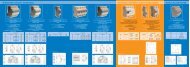
IP 55 Modular Cabinets
IP 55 Modular Cabinets
IP 55 Modular Cabinets

You also want an ePaper? Increase the reach of your titles
YUMPU automatically turns print PDFs into web optimized ePapers that Google loves.
Quadritalia Srl<br />
www.quadritalia.com - info@quadritalia.com<br />
PROTECTION FOR YOUR ELECTRONICS<br />
Headquarter:<br />
Via E. Mattei, 6/10<br />
36040 Brendola (Vicenza) - Italy<br />
Tel. +39 0444 601744<br />
Fax +39 0444 601057<br />
Second manufacturing unit:<br />
Via del Laghetto, 290<br />
45021 Badia Polesine<br />
(Rovigo) - Italy<br />
BOZZA DI STAMPA<br />
general catalogue<br />
21<br />
General Catalogue<br />
21<br />
® Copyright by Quadritalia srl<br />
All rights reserved.<br />
No part of this publication may be reproduced, stored in retrieval systems or transmitted, in any form or by any means, electronic, mechanical, photocopying, recording or otherwise, without the prior written permission of the Publisher.<br />
All details and pictures are subject to change without notice and are not binding the Manufacturer
20th year<br />
with love<br />
BOZZA DI STAMPA<br />
Thank you<br />
to all of our Customers, Suppliers and<br />
Collaborators, who have enabled us to work<br />
with enthusiasm and professionalism, to<br />
ensure the success of the Quadritalia<br />
trademark throughout the world and to<br />
become the Company we are today.
BOZZA DI STAMPA
Quadritalia in the world<br />
BOZZA DI STAMPA<br />
• = Quadritalia’s presence on world markets<br />
• = Quadritalia’s new objectives
United States - Canada - Brazil - Russia - Ukraine - Poland - Lithuania - Romania - Slovakia - Slovenia - Denmark<br />
Norway - Sweden - Tunisia - Egypt - Cyprus - Greece - Germany - Spain - Portugal - France - Switzerland – Austria<br />
BOZZA DI STAMPA
OUR OPERATIONAL HEADQUARTERS<br />
TORINO<br />
GENOVA<br />
MILANO<br />
VERONA<br />
BOLOGNA<br />
FIRENZE<br />
VICENZA<br />
ROVIGO<br />
VENEZIA<br />
ROMA<br />
BOZZA DI STAMPA<br />
PALERMO<br />
NAPOLI
VERONA<br />
Headquarter:<br />
Brendola<br />
(VICENZA)<br />
VICENZA<br />
Second<br />
manufacturing unit:<br />
Badia Polesine<br />
(ROVIGO)<br />
ROVIGO<br />
VENEZIA<br />
BOZZA DI STAMPA
Our Company<br />
Founded in 1988 to produce modular metal carpentry<br />
for the electronics and electro technical industries,<br />
our Company immediately distinguished itself<br />
for the quality and completeness of its products.<br />
Our production, which is entirely automated with<br />
robotic plants, includes a considerable range of<br />
standard and customised products (see boring,<br />
painting and non-serial productions), providing complete<br />
service for the final user, in rationally short<br />
times.<br />
Design, continuous research and the certifications<br />
of our products guarantee the highest possible level<br />
of quality and great dependability.<br />
The advantage that our Company offers is to understand<br />
the individual requirements of each customer,<br />
in real time, and to satisfy them as quickly as possible,<br />
becoming a veritable “business partner”.<br />
BOZZA DI STAMPA
The entire production is programmed by the technical office through<br />
CAD/CAM stations, which directly pilot the processing line in the shop.<br />
Non-standard and customised products are also designed and developed<br />
here.<br />
The commercial office is at the complete disposal of customers to<br />
request materials, make estimates and provide consultancy on the use<br />
of our range of products.<br />
The sheet metal processing lines utilise state<br />
of the art production technologies, capable of<br />
guaranteeing top quality standards and the<br />
greatest possible speed in production.<br />
BOZZA DI STAMPA
Our Company<br />
The entire painting cycle takes place on an automated robotic<br />
plant. Equipped with three painting cabins, the system permits<br />
extremely rapid performance of customised or non-standard<br />
painting jobs.<br />
Traditional bending systems are integrated<br />
with a completely automatic finishing line,<br />
managed without the assistance of human<br />
workers.<br />
The robotic welding island with several stations permits complete<br />
assembly of cabinets, boxes and consoles, rapidly and with great precision.<br />
BOZZA DI STAMPA
The polyurethane foam gaskets, which are continuous cast directly on<br />
doors and panels, guarantee perfect protection of our products from<br />
water and dust (certified and approved).<br />
The warehouse and assembly department, where the metal carpentry<br />
is carefully assembled and equipped with all of the required accessories.<br />
Our motor pool, which loads the products at the warehouse in Vicenza and transports them directly to their destination at the customer’s premises,<br />
with no further manipulation, thereby guaranteeing extremely rapid delivery time.<br />
Our Certifications - TOTAL GUARANTEES FOR THE GLOBAL MARKET<br />
BOZZA DI STAMPA<br />
PRODUCT SERVICE
BOZZA DI STAMPA<br />
21 CATALOGUE<br />
1
BOZZA DI STAMPA<br />
21 CATALOGUE<br />
2
GENERAL TABLE OF CONTENTS<br />
Description of Article<br />
Page<br />
General Table of Contents Page 3<br />
Electronic Mail Page 7<br />
<strong>IP</strong> <strong>55</strong> AX <strong>Modular</strong> <strong>Cabinets</strong>, General Description, Page 8<br />
AX Cabinet Frames Page 10<br />
AX <strong>Cabinets</strong> with single door Page 12<br />
AX <strong>Cabinets</strong> with double door Page 14<br />
AXV <strong>Cabinets</strong> with transparent door and internal door Page 16<br />
Cabinet with double transparent door and internal door Page 18<br />
Blind doors for AX, AZ, AF and AS series frames Page 19<br />
Transparent doors for AX, AZ, AF and AS series frames Page 20<br />
Blind doors for AX, AZ, AF and AS series frames Page 21<br />
Blind rear panels for AX, AZ and AF series cabinets Page 22<br />
Side panels for AX cabinets Page 23<br />
Side panels pairs for AX cabinets Page 23<br />
Joining AX cabinets in batteries Page 24<br />
AX, AZ, AF and AS cabinet front electro mechanical plate Page 25<br />
AX, AZ, AF and AS cabinet front plate assembly kit and instructions Page 26<br />
AX, AZ and AF cabinet double front plate assembly kit and instructions Page 27<br />
AX, AZ and AF cabinet front plate joint band Page 28<br />
AX and AF cabinet front plate backspacing kit Page 29<br />
Enlarged plate and lateral insertion of plate for AX and AZ cabinets Page 30<br />
Bases, corners, front and rear parts H = 100 mm Page 31<br />
Side flanges for bases H = 100 mm Page 31<br />
Assembled bases H = 100 Page 32<br />
Corner bases H = 200 mm Page 33<br />
Bases, front and side pairs H = 200 mm Page 33<br />
Floor-closed bases H = 200 mm Page 34<br />
Lowered side flanges for bases Page 35<br />
Extended base for cabinets in batteries Page 35<br />
AXN series PC cabinet Page 36<br />
Floppy disk slot Page 37<br />
AX cabinet printer carriage Page 38<br />
AX cabinet airtight cubicle Page 38<br />
AX and AZ cabinet sliding drawer Page 38<br />
AX and AZ cabinet reduced electro mechanical plate Page 38<br />
PC cabinet with lateral bands Page 39<br />
PC cabinet with lateral bands on column Page 40<br />
<strong>Modular</strong> cabinet, internal modular system Page 41<br />
Instrument panels with various bores Page 43<br />
Panels for modules with single slot Page 43<br />
Closed instrument panels Page 44<br />
Double closed instrument panels Page 44<br />
Triple closed instrument panels Page 44<br />
Upper and lower compensation panels Page 44<br />
Component plate Page 44<br />
<strong>Modular</strong> internal frame with compensation panels Page 45<br />
Crosspieces for attachment of DIN bars Page 45<br />
DIN Bar Page 45<br />
Blind modular external door Page 46<br />
Transparent modular external door Page 46<br />
Reduced internal equipment plate Page 46<br />
Reduced horizontal partitions Page 47<br />
Reduced vertical partitions for AZ cabinets Page 47<br />
Reduced vertical partitions Page 47<br />
Rabbet crosspiece for AX and AZ cabinet doors Page 47<br />
Cabinet with front console Page 48<br />
Lateral cable raceway Page 50<br />
BOZZA DI STAMPA<br />
21 CATALOGUE<br />
3
GENERAL TABLE OF CONTENTS<br />
Description of Article<br />
Page<br />
Front cable raceway Page 52<br />
Blind plate lateral cable raceway for RLX cabinet Page 53<br />
Pre-bored plate for 24 pole connectors for RLX cabinet Page 53<br />
Blind PLF 24 pole plate for RLX cabinet Page 53<br />
24-pole reduction plate for RLX cabinet Page 53<br />
AX series 19” Rack Cabinet Page 54<br />
AXR series 19” open rack cabinet Page <strong>55</strong><br />
AXR 19” internal swivel rack frame Page <strong>55</strong><br />
Fixed vertical strut pairs for AXR 19” rack Page <strong>55</strong><br />
AXR cabinet front panels in aluminium of various He units Page <strong>55</strong><br />
Rack handle Page <strong>55</strong><br />
<strong>IP</strong> <strong>55</strong> AZ series <strong>Modular</strong> <strong>Cabinets</strong>, General Description, Page 56<br />
AZ series cabinet frame with upper and lower closure Page 58<br />
AZ series cabinets with single door Page 60<br />
AZ series cabinets with double door Page 62<br />
AZ series cabinets with single transparent door and internal door Page 64<br />
AZ series cabinets with double transparent door and internal door Page 66<br />
AZ series cabinet joining kit and assembly instructions Page 67<br />
Side panels for AZ cabinets Page 68<br />
Side panel pairs for AZ cabinets Page 68<br />
AZ series front plate backspacing kit Page 69<br />
AZ series PC cabinet Page 70<br />
AZN cabinet printer carriage Page 71<br />
AZ <strong>Modular</strong> cabinet, internal modular system Page 72<br />
AZ Cabinet with front console Page 74<br />
AZ series lateral raceway Page 76<br />
AZ series front raceway Page 78<br />
AZ series 19” rack cabinet Page 79<br />
AX, AZ and AF series horizontal partitions Page 80<br />
AZ series vertical partitions Page 80<br />
AZ series vertical partitions Page 80<br />
AX and AZ series cabinet roof raceway Page 81<br />
Cable entry compartment, types and customisations Page 82<br />
Cable entry compartment, types and customisations Page 84<br />
<strong>IP</strong> <strong>55</strong> AF series <strong>Modular</strong> <strong>Cabinets</strong>, General Description, Page 86<br />
AF Cabinet mono-block Frames Page 87<br />
AF Cabinet with single door Page 88<br />
AF Cabinet with double door Page 89<br />
AF <strong>Cabinets</strong> with transparent door and internal door Page 90<br />
AF Cabinet with double transparent door and internal door Page 91<br />
AF modular cabinet with internal modular frame Page 92<br />
AF cabinet horizontal mono-block frame Page 93<br />
AF series horizontal cabinet Page 94<br />
Cable entry compartment, types and customisations Page 95<br />
<strong>IP</strong> <strong>55</strong> mono-block AS series cabinets, general description Page 96<br />
AS series mono-block frame Page 97<br />
AS series mono-block cabinet with single door Page 98<br />
AS series mono-block cabinet with single transparent door and internal blind door Page 99<br />
AS series modular mono-block cabinet Page 100<br />
<strong>IP</strong> 65 ST series airtight boxes, general description Page 101<br />
<strong>IP</strong> 65 airtight box with single door Page 102<br />
<strong>IP</strong> 65 airtight boxes with single transparent door and internal door Page 104<br />
STB box blind door Page 105<br />
STB box transparent door Page 105<br />
STB box blind internal door Page 106<br />
STB box blind internal plate Page 106<br />
<strong>IP</strong> 65 ST series modular airtight boxes Page 107<br />
BOZZA DI STAMPA<br />
21 CATALOGUE<br />
4
GENERAL TABLE OF CONTENTS<br />
Description of Article<br />
Page<br />
ST box modular internal kit Page 107<br />
STM box blind modular panel Page 108<br />
STM box blind modular instrument panel Page 108<br />
STM box contiguous modular instrument panels Page 108<br />
STM box double blind modular panel Page 108<br />
ST box cable compartment Page 109<br />
Wall attachment kit for ST pensile box Page 110<br />
Rain protection roof for ST box Page 110<br />
Double door for <strong>IP</strong> 65 ST series airtight box Page 111<br />
Cable compartment for <strong>IP</strong> 65 ST box with double door Page 112<br />
Internal plate for ST series box with double door Page 113<br />
Doors for ST series box with double door Page 113<br />
<strong>IP</strong> <strong>55</strong> shunt box with cover Page 114<br />
<strong>IP</strong> <strong>55</strong> shunt boxes with transparent cover Page 115<br />
Plate for CDB shunt box Page 116<br />
<strong>IP</strong> <strong>55</strong> Consoles, general characteristics Page 117<br />
<strong>IP</strong> <strong>55</strong> LC series consoles Page 118<br />
LC series console base Page 119<br />
LCA riser for LC series modular consoles Page 120<br />
LCM shelf for LC series modular consoles Page 121<br />
Casing for LC series console riser Page 122<br />
<strong>IP</strong> <strong>55</strong> BLC mono-block console Page 123<br />
<strong>IP</strong> <strong>55</strong> BLD mono-block console Page 124<br />
<strong>IP</strong> <strong>55</strong> LMC mono-block console Page 125<br />
<strong>IP</strong> <strong>55</strong> BLC and LMC type console riser Page 126<br />
<strong>IP</strong> <strong>55</strong> LAS mono-block console with shelf and riser Page 127<br />
<strong>IP</strong> <strong>55</strong> LAR console with riser Page 128<br />
Accessories Page 129<br />
STL section, lateral for AZ Page 130<br />
XTL section, lateral for AX Page 130<br />
FTL section, lateral for AF Page 130<br />
STL2 section, reinforced lateral for AZ Page 131<br />
XTL2 section, reinforced lateral for AX Page 131<br />
STZ section, frontal for AZ Page 131<br />
STZ section, frontal for AZ Page 132<br />
STA pre-bored vertical strut, L = 2000 mm Page 132<br />
STF pre-bored vertical strut, L = 2000 mm Page 132<br />
SGD section for application of DIN guides Page 133<br />
Bracket for SGD section Page 133<br />
SGD and CPS5846 section kit Page 133<br />
Cable attachment section Page 133<br />
Interior door section Page 134<br />
Interior door console for cabinets Page 134<br />
Transformer section Page 135<br />
Brace for console Page 136<br />
BCO170 cabinet door blockage kit Page 136<br />
Door block for boxes Page 137<br />
BCO100 mechanical door block Page 137<br />
BCO110 mechanical cabinet door block Page 138<br />
Gas spring kit Page 138<br />
Screen slot Page 139<br />
Eyebolts Page 139<br />
Assorted eyebolt kit Page 140<br />
Heavy-duty eyebolt Page 140<br />
Eyebolts with extension Page 141<br />
Lifting beams Page 141<br />
Lifting criteria Page 142<br />
Lifting beam codes Page 143<br />
BOZZA DI STAMPA<br />
21 CATALOGUE<br />
5
GENERAL TABLE OF CONTENTS<br />
Description of Article<br />
Page<br />
Aluminium protective windows Page 144<br />
The various auxiliary brackets and components kits Page 145<br />
Hinges, kit for cabinets, boxes and consoles Page 147<br />
Adjustable feet Page 150<br />
Wheel supports Page 150<br />
Light wheels Page 151<br />
Orientable wheels Page 151<br />
Flanged nuts Page 153<br />
Cage nuts Page 153<br />
Screws Page 153<br />
Bolts with nuts Page 153<br />
Side spacer Page 153<br />
Spacer for rear and joining of cabinets Page 153<br />
Support for lateral insertion of plate Page 154<br />
180° hinge for internal rack frame Page 154<br />
Corner pieces for tubular door reinforcements Page 154<br />
Guillotine style cable conduit Page 1<strong>55</strong><br />
Pins for plate support Page 156<br />
Closure Boxes and cables Page 157<br />
Handles Page 158<br />
Ventilation systems Page 160<br />
Filters and fans Page 161<br />
Fans Page 162<br />
Ventilation roofs Page 163<br />
Ventilation roofs and fans Page 163<br />
Wall-mounted air conditioners Page 164<br />
Wall-mounted conditioner boring template Page 165<br />
Roof-mounted air conditioners Page 166<br />
Roof-mounted conditioner boring template Page 167<br />
Air-to-air heat exchangers Page 168<br />
Air-to-water heat exchangers Page 169<br />
Partial encasement frame for CF-P Page 170<br />
Anti-condensation resistances Page 171<br />
Temperature alarm thermostats Page 172<br />
Micro Switches Page 172<br />
Light bulbs Page 172<br />
Flashing light devices Page 173<br />
Gaskets Page 174<br />
Spray colours for touch ups Page 174<br />
Braces for electro magnetic compatibility Page 175<br />
Electromagnetic compliance Page 176<br />
Levels of protection, technical card Page 177<br />
CESI Certification Page 178<br />
TUV Certification Page 178<br />
CSA Certification Page 178<br />
<strong>Modular</strong> suspension systems Page 179<br />
Anchoring base for modular suspension systems Page 180<br />
Intermediate connections for modular suspensions Page 182<br />
Swivel terminal connections for modular suspensions Page 184<br />
Tubes for modular suspensions Page 186<br />
Pensile boxes for modular suspensions Page 187<br />
<strong>Modular</strong> interface systems Page 188<br />
<strong>Modular</strong> bar systems Page 189<br />
Painting Cycle Page 190<br />
Electronics cabinets Page 192<br />
Customisations on order of clients Page 193<br />
General Table of Contents for code prefixes Page 198<br />
BOZZA DI STAMPA<br />
21 CATALOGUE<br />
6
ELECTRONIC MAIL<br />
TO CONTACT OUR COLLABORATORS:<br />
Website:<br />
http://www.quadritalia.com<br />
General E-mail:<br />
info@quadritalia.com<br />
Management:<br />
Mr. FLAVIO SANSON<br />
Ing. RODOLFO SANSON<br />
Mr. MAURO SANSON<br />
Mr. STEFANO SANSON<br />
Sales Office:<br />
Ms. ELISABETTA TRAPANI<br />
Ms. GIULIANA MASSIGNAN<br />
Technical Office:<br />
Mr. STEFANO SANSON - IN CHARGE<br />
Mr. SERGIO LORENZIN - DESIGN<br />
Mr. GIORGIO MELATO - RESEARCH & DEVELOPMENT<br />
f.sanson@quadritalia.com<br />
r.sanson@quadritalia.com<br />
m.sanson@quadritalia.com<br />
s.sanson@quadritalia.com<br />
e.trapani@quadritalia.com<br />
g.massignan@quadritalia.com<br />
s.lorenzin@quadritalia.com<br />
BOZZA DI STAMPA<br />
Administration Office:<br />
Mr. GIORGIO LUPAZZI - IN CHARGE<br />
g.lupazzi@quadritalia.com<br />
Ms. NANCY BASTON<br />
21 CATALOGUE<br />
7
AX – <strong>IP</strong> <strong>55</strong> MODULAR CABINETS<br />
AX series cabinets are produced on the same line as the AZ<br />
series and are oriented towards a market that is sensitive to<br />
the cost-effectiveness of products, but also pays attention to<br />
the quality and technical-operational features required by the<br />
norms in force.<br />
The structures of these cabinets are completely welded and<br />
built of top quality press-bent sheet metal, so that the roof and<br />
bottom of the cabinet form a solid body with the four vertical<br />
uprights, creating an extremely rigid frame.<br />
The structure lends itself to modular combination with other<br />
elements in an extremely simple manner, minimising assembly<br />
costs. The painting cycle is performed by automatic plants, following<br />
degreasing, phosphation with iron phosphates and several<br />
successive phases of rinsing.<br />
The following stage consists of kiln drying and painting in a<br />
completely automatic cabin.<br />
Thermal hardening epoxy polyester type powders are used for<br />
the painting. The totally automatic production cycle guarantees<br />
the utmost precision, homogeneity and constant quality over<br />
the long term. Thanks to the polyurethane foam gasket installed<br />
with an automatic continuous gluing system, the <strong>IP</strong> <strong>55</strong> level<br />
of protection has been declared and certified.<br />
Fig. 8.1<br />
COMPONENTS OF THE BASIC CABINET<br />
The bearing structure is produced from completely welded<br />
drawn and perforated galvanised sheet steel sections, which<br />
guarantee mechanical sturdiness and total protection against<br />
water and dust, thereby consenting the firm to obtain the <strong>IP</strong> <strong>55</strong><br />
level of protection.<br />
The rear panel is made from press-bent sheet steel with centring<br />
bores to facilitate attachment with 6/8 M6 screws and is<br />
equipped with a gasket around the border that adapts perfectly<br />
to the structure.<br />
The fixed bottom in press-bent sheet steel has bores for the<br />
passage of cables and is equipped with the relative covers.<br />
The interior equipment installation plate is in 25/10 thick galvanised<br />
sheet steel and has double reinforcement fins along the<br />
entire perimeter. On request cabinet is also equipped with slides<br />
and pins to facilitate ubsertion of plate.<br />
BOZZA DI STAMPA<br />
8<br />
21 CATALOGUE
AX – <strong>IP</strong> <strong>55</strong> MODULAR CABINETS<br />
The basic cabinet also has upper and lower bores on the sides<br />
to adjust the depth of the interior plate.<br />
Accessories for the attachment and adjustment of the interior<br />
plate are also provided.<br />
The reversible hinged front door has an angle of aperture of<br />
120° (which may be increased to 180° on request); it is built<br />
from 20/10 thick sheet steel and has a gasket around the perimeter<br />
that adapts perfectly to the structure. The door also has<br />
an inner perforated frame to facilitate attachment of the<br />
cabling raceways and other accessories, thus also conferring<br />
greater rigidity. The lever bolt system of closure is situated<br />
outside the airtight area and has 4 points of attachment (any<br />
type of handle is available on request). Copper-plated M6<br />
screws are used for the earth connection and are applied on all<br />
removable parts, including the door, thereby guaranteeing electrical<br />
continuity throughout the structure.<br />
ADDITIONAL COMPONENTS:<br />
100 mm H base, with lateral, front and rear flanges to permit<br />
easy communication between combined modules or passage of<br />
cables. A vast assortment of optional accessories is available<br />
on request, which confer the “AX SERIES” cabinet with great<br />
modular component features and flexibility.<br />
Level of protection <strong>IP</strong> <strong>55</strong>.<br />
Fig. 9.1<br />
OPTIONAL VARIANTS FOR OTHER CONFIGURATIONS OF THE<br />
BASIC CABINET<br />
“AX SERIES”<br />
“AXB” – Blind and/or perforated external door (on request);<br />
“AXV” – Blind and/or perforated internal door and transparent<br />
external door;<br />
“AXD” – Blind and/or perforated internal modular panels and<br />
transparent external door;<br />
“AXR” – 19” Rack Panels with swivel frame and transparent<br />
external door;<br />
“AXN” – Doors with observation window and drawer for<br />
keyboard;<br />
“AXL” – Upper and lower door, central console and rear door;<br />
“AXW” – Like the “AXN”, but with coloured lateral bands;<br />
“AXY” – Monitor and PC column.<br />
BOZZA DI STAMPA<br />
21 CATALOGUE<br />
9
AX – AX CABINET FRAME<br />
The frame is the basic structural element of the AX modular cabinet. It is made up of the bottom, the roof and four vertical struts<br />
in sheet metal bent with numerically controlled machinery, to ensure optimum precision in measurements and connection between<br />
the pieces.<br />
The bottom is open to permit the passage of cables and is technically prepared for attachment of the closure plate to ensure total<br />
protection from water and dust, as required by the <strong>IP</strong> <strong>55</strong> protection standards. The upper part is completely blind, except for the<br />
four bores near the corners, where four blind threaded blocks are welded for the insertion of eyebolts for lifting. The bottom and<br />
roof are assembled with the vertical struts on a robotic welding bench with several stations, and<br />
after inspection to ensure the orthogonal precision of the structure, they are welded by a robot<br />
(see fig. 10.1).<br />
When the welding is complete the frame is finished and will then be washed, degreased and painted.<br />
The exterior is completely closed and ready for attachment of the doors, side and rear panels.<br />
Along the perimeter of the interior there are two rows of alternating rectangular and circular<br />
bores at a fixed distance from each other, to permit easy attachment of modular components<br />
and accessories to obtain the various final versions of the cabinet. Frames having a width of less<br />
than 1400 mm have no central vertical strut, while frames with a width greater than 1400 mm<br />
have a central rear vertical uprights (see figs. 10.2 and 10.3).<br />
H<br />
AX FRAME without vertical rear strut<br />
W<br />
E<br />
C<br />
D<br />
G<br />
H<br />
E<br />
AX FRAME with central vertical rear strut<br />
P<br />
Fig. 10.1<br />
BOZZA DI STAMPA<br />
F<br />
Cable passage compartment<br />
with closure plate.<br />
Fig. 10.2 Fig. 10.3<br />
C<br />
G<br />
D<br />
- H, W and D Dimensions are nominal, therefore they correspond to the size of the cabinet with doors, rear and side panels mounted;<br />
- The frame is supplied as a standard feature with cabling bores and closure plate;<br />
- Frames measuring 1600 and 1800 mm have two rear panels screwed to a central upright strut;<br />
- Eyebolts and screws are not included in the code shown.<br />
10<br />
21 CATALOGUE
AX – AX CABINET FRAME<br />
Nominal Dimensions Characteristics<br />
CODE H W D C G E F<br />
AX1664 1600 600 400 1502 499 243 1494<br />
AX1665 1600 600 500 1502 499 343 1494<br />
AX1666 1600 600 600 1502 499 443 1494<br />
AX1684 1600 800 400 1502 699 243 1494<br />
AX1685 1600 800 500 1502 699 343 1494<br />
AX1686 1600 800 600 1502 699 443 1494<br />
AX1844 1800 400 400 1702 299 243 1694<br />
AX1845 1800 400 500 1702 299 343 1694<br />
AX1846 1800 400 600 1702 299 443 1694<br />
AX1848 1800 400 800 1702 299 643 1694<br />
AX1864 1800 600 400 1702 499 243 1694<br />
AX1865 1800 600 500 1702 499 343 1694<br />
AX1866 1800 600 600 1702 499 443 1694<br />
AX1868 1800 600 800 1702 499 643 1694<br />
AX1884 1800 800 400 1702 699 243 1694<br />
AX1885 1800 800 500 1702 699 343 1694<br />
AX1886 1800 800 600 1702 699 443 1694<br />
AX1888 1800 800 800 1702 699 643 1694<br />
AX188A 1800 800 1000 1702 699 843 1694<br />
AX18E6 1800 1600 600 1702 1499 443 1694 699<br />
AX18E8 1800 1600 800 1702 1499 643 1694 699<br />
AX18F5 1800 1800 500 1702 1699 343 1694 799<br />
AX18F6 1800 1800 600 1702 1699 443 1694 799<br />
AX18F8 1800 1800 800 1702 1699 643 1694 799<br />
AX20E4 2000 1600 400 1902 1499 243 1894 699<br />
AX20E5 2000 1600 500 1902 1499 343 1894 699<br />
- Dimensions in mm<br />
DIMENSIONS OF AX FRAMES WITHOUT VERTICAL REAR STRUT<br />
AX18A4 1800 1000 400 1702 899 243 1694<br />
AX2265 2200 600 500 2102 499 343 2094<br />
AX18A5 1800 1000 500 1702 899 343 1694<br />
AX2266 2200 600 600 2102 499 443 2094<br />
AX18A6 1800 1000 600 1702 899 443 1694<br />
AX2268 2200 600 800 2102 499 643 2094<br />
AX18A8 1800 1000 800 1702 899 643 1694<br />
AX226A 2200 600 1000 2102 499 843 2094<br />
AX18AA 1800 1000 1000 1702 899 843 1694<br />
AX2284 2200 800 400 2102 699 243 2094<br />
AX18C4 1800 1200 400 1702 1099 243 1694<br />
AX2285 2200 800 500 2102 699 343 2094<br />
AX18C5 1800 1200 500 1702 1099 343 1694<br />
AX2286 2200 800 600 2102 699 443 2094<br />
AX18C6 1800 1200 600 1702 1099 443 1694<br />
AX2288 2200 800 800 2102 699 643 2094<br />
AX18C8 1800 1200 800 1702 1099 643 1694<br />
AX228A 2200 800 1000 2102 699 843 2094<br />
AX18CA 1800 1200 1000 1702 1099 843 1694<br />
AX22A4 2200 1000 400 2102 899 243 2094<br />
AX18D4 1800 1400 400 1702 1299 243 1694<br />
AX22A5 2200 1000 500 2102 899 343 2094<br />
AX18D5 1800 1400 500 1702 1299 343 1694<br />
AX22A6 2200 1000 600 2102 899 443 2094<br />
AX18D6 1800 1400 600 1702 1299 443 1694<br />
AX22A8 2200 1000 800 2102 899 643 2094<br />
AX18D8 1800 1400 800 1702 1299 643 1694<br />
AX22AA 2200 1000 1000 2102 899 843 2094<br />
Nominal Dimensions<br />
DIMENSIONS OF AX FRAMES WITH VERTICAL REAR STRUT<br />
Characteristics<br />
CODE H W D C G E F R<br />
AX18E4 1800 1600 400 1702 1499 243 1694 699<br />
AX18E5 1800 1600 500 1702 1499 343 1694 699<br />
Nominal Dimensions Characteristics<br />
CODE H W D C G E F<br />
AX2044 2000 400 400 1902 299 243 1894<br />
AX2045 2000 400 500 1902 299 343 1894<br />
AX2046 2000 400 600 1902 299 443 1894<br />
AX2048 2000 400 800 1902 299 643 1894<br />
AX2064 2000 600 400 1902 499 243 1894<br />
AX2065 2000 600 500 1902 499 343 1894<br />
AX2066 2000 600 600 1902 499 443 1894<br />
AX2068 2000 600 800 1902 499 643 1894<br />
AX2084 2000 800 400 1902 699 243 1894<br />
AX2085 2000 800 500 1902 699 343 1894<br />
AX2086 2000 800 600 1902 699 443 1894<br />
AX2088 2000 800 800 1902 699 643 1894<br />
AX208A 2000 800 1000 1902 699 843 1894<br />
AX20A4 2000 1000 400 1902 899 243 1894<br />
AX20A5 2000 1000 500 1902 899 343 1894<br />
AX20A6 2000 1000 600 1902 899 443 1894<br />
AX20A8 2000 1000 800 1902 899 643 1894<br />
AX20AA 2000 1000 1000 1902 899 843 1894<br />
AX2264 2200 600 400 2102 499 243 2094<br />
BOZZA DI STAMPA<br />
Nominal Dimensions<br />
Characteristics<br />
CODE H W D C G E F R<br />
AX20E6 2000 1600 600 1902 1499 443 1894 699<br />
AX20E8 2000 1600 800 1902 1499 643 1894 699<br />
AX20F5 2000 1800 500 1902 1699 343 1894 799<br />
AX20F6 2000 1800 600 1902 1699 443 1894 799<br />
AX20F8 2000 1800 800 1902 1699 643 1894 799<br />
AX22E5 2200 1600 500 2102 1499 343 2094 699<br />
AX22E6 2200 1600 600 2102 1499 443 2094 699<br />
AX22E8 2200 1600 800 2102 1499 643 2094 699<br />
- - - - - - - - -<br />
21 CATALOGUE<br />
11
AXB – CABINET WITH SINGLE DOOR<br />
“AXB” SERIES CABINET WITH SINGLE DOOR, COMPLETE WITH:<br />
- Frame<br />
- Blind front door;<br />
- Rear panel;<br />
- Galvanised electromechanical plate.<br />
Fig. 12.1<br />
H<br />
Y<br />
W<br />
G<br />
I<br />
D<br />
NOTE:<br />
- Eyebolts are not included;<br />
- <strong>Cabinets</strong> with widths of 400, 600, 800 and 1000 mm have<br />
a single front door;<br />
- <strong>Cabinets</strong> having a width of 800 and 1000 mm may also<br />
have two doors with rabbets, on request;<br />
- The measurements of the electromechanical plates are<br />
shown to facilitate identification; see page 25, PNA for the<br />
characteristics of the plates;<br />
- For the side panels of the cabinet, see page 23, SPL or CPL-<br />
For the base of the cabinet see page 31, ZCB;<br />
- For the accessories see pages 24-35.<br />
BOZZA DI STAMPA<br />
X<br />
S<br />
T<br />
R<br />
A<br />
Fig. 12.2<br />
Fig. 12.3<br />
21 CATALOGUE<br />
12
AXB – CABINET WITH SINGLE DOOR<br />
- Dimensions in mm<br />
CODES AND CHARACTERISTIC DIMENSIONS<br />
Nominal Dimensions Characteristics Plate<br />
CODE H W D A G I R S T X Y<br />
AXB1664 1600 600 400 1594 544 310 592 440 1444 490 1480<br />
AXB1665 1600 600 500 1594 544 410 592 440 1444 490 1480<br />
AXB1666 1600 600 600 1594 544 510 592 440 1444 490 1480<br />
AXB1684 1600 800 400 1594 744 310 792 640 1444 690 1480<br />
AXB1685 1600 800 500 1594 744 410 792 640 1444 690 1480<br />
AXB1686 1600 800 600 1594 744 510 792 640 1444 690 1480<br />
AXB1844 1800 400 400 1794 344 310 392 240 1644 290 1680<br />
AXB1845 1800 400 500 1794 344 410 392 240 1644 290 1680<br />
AXB1846 1800 400 600 1794 344 510 392 240 1644 290 1680<br />
AXB1848 1800 400 800 1794 344 710 392 240 1644 290 1680<br />
AXB1864 1800 600 400 1794 544 310 592 440 1644 490 1680<br />
AXB1865 1800 600 500 1794 544 410 592 440 1644 490 1680<br />
AXB1866 1800 600 600 1794 544 510 592 440 1644 490 1680<br />
AXB1868 1800 600 800 1794 544 710 592 440 1644 490 1680<br />
AXB1884 1800 800 400 1794 744 310 792 640 1644 690 1680<br />
AXB1885 1800 800 500 1794 744 410 792 640 1644 690 1680<br />
AXB1886 1800 800 600 1794 744 510 792 640 1644 690 1680<br />
AXB1888 1800 800 800 1794 744 710 792 640 1644 690 1680<br />
AXB188A 1800 800 1000 1794 744 910 792 640 1644 690 1680<br />
AXB18A4 1800 1000 400 1794 944 310 992 840 1644 890 1680<br />
AXB18A5 1800 1000 500 1794 944 410 992 840 1644 890 1680<br />
AXB18A6 1800 1000 600 1794 944 510 992 840 1644 890 1680<br />
AXB18A8 1800 1000 800 1794 944 710 992 840 1644 890 1680<br />
AXB18AA 1800 1000 1000 1794 944 910 992 840 1644 890 1680<br />
AXB2044 2000 400 400 1994 344 310 392 240 1844 290 1880<br />
AXB2045 2000 400 500 1994 344 410 392 240 1844 290 1880<br />
AXB2046 2000 400 600 1994 344 510 392 240 1844 290 1880<br />
AXB2048 2000 400 800 1994 344 710 392 240 1844 290 1880<br />
AXB2064 2000 600 400 1994 544 310 592 440 1844 490 1880<br />
AXB2065 2000 600 500 1994 544 410 592 440 1844 490 1880<br />
AXB2066 2000 600 600 1994 544 510 592 440 1844 490 1880<br />
AXB2068 2000 600 800 1994 544 710 592 440 1844 490 1880<br />
AXB2084 2000 800 400 1994 744 310 792 640 1844 690 1880<br />
AXB2085 2000 800 500 1994 744 410 792 640 1844 690 1880<br />
AXB2086 2000 800 600 1994 744 510 792 640 1844 690 1880<br />
AXB2088 2000 800 800 1994 744 710 792 640 1844 690 1880<br />
AXB208A 2000 800 1000 1994 744 910 792 640 1844 690 1880<br />
AXB20A4 2000 1000 400 1994 944 310 992 840 1844 890 1880<br />
AXB20A5 2000 1000 500 1994 944 410 992 840 1844 890 1880<br />
AXB20A6 2000 1000 600 1994 944 510 992 840 1844 890 1880<br />
AXB20A8 2000 1000 800 1994 944 710 992 840 1844 890 1880<br />
AXB20AA 2000 1000 1000 1994 944 910 992 840 1844 890 1880<br />
AXB2264 2200 600 400 2194 544 310 592 440 2044 490 2080<br />
AXB2265 2200 600 500 2194 544 410 592 440 2044 490 2080<br />
AXB2266 2200 600 600 2194 544 510 592 440 2044 490 2080<br />
AXB2268 2200 600 800 2194 544 710 592 440 2044 490 2080<br />
AXB226A 2200 600 1000 2194 544 910 592 440 2044 490 2080<br />
AXB2284 2200 800 400 2194 744 310 792 640 2044 690 2080<br />
AXB2285 2200 800 500 2194 744 410 792 640 2044 690 2080<br />
AXB2286 2200 800 600 2194 744 510 792 640 2044 690 2080<br />
AXB2288 2200 800 800 2194 744 710 792 640 2044 690 2080<br />
AXB228A 2200 800 1000 2194 744 910 792 640 2044 690 2080<br />
AXB22A4 2200 1000 400 2194 944 310 992 840 2044 890 2080<br />
AXB22A5 2200 1000 500 2194 944 410 992 840 2044 890 2080<br />
AXB22A6 2200 1000 600 2194 944 510 992 840 2044 890 2080<br />
AXB22A8 2200 1000 800 2194 944 710 992 840 2044 890 2080<br />
AXB22AA 2200 1000 1000 2194 944 910 992 840 2044 890 2080<br />
BOZZA DI STAMPA<br />
- The measurements of the electromechanical plates are shown to facilitate identification; see page 25, PNA for the characteristics<br />
of the plates , dimensions (x,y)<br />
21 CATALOGUE<br />
13
AXB – CABINET WITH DOUBLE DOOR<br />
“AXB” SERIES CABINET WITH DOUBLE DOOR, COMPLETE<br />
WITH:<br />
- Frame;<br />
- Front doors with blind rabbet;<br />
- Rear panel(s);<br />
- Galvanised electromechanical plate(s).<br />
H<br />
Y<br />
W<br />
G<br />
I<br />
D<br />
Fig. 14.1<br />
NOTE:<br />
- Eyebolts are not included (see pg. 140);<br />
- <strong>Cabinets</strong> having a width of 1200, 1400, 1600 or 1800<br />
mm have two doors with rabbets;<br />
- <strong>Cabinets</strong> having a width of 1600 and 1800 mm have<br />
two rear panels attached with screws and a central vertical<br />
strut;<br />
- The measurements of the electromechanical plates are<br />
shown to facilitate identification; see page 25 for the<br />
characteristics of the plates;<br />
- <strong>Cabinets</strong> having a width of 1600 and 1800 mm are<br />
equipped with two plates, joined together with screws;<br />
- See page 23 for the side panels of the cabinet;<br />
- For the base of the cabinet see page 31;<br />
- For the accessories see pages 150-1<strong>55</strong>.<br />
BOZZA DI STAMPA<br />
R<br />
X<br />
S<br />
T<br />
B<br />
A<br />
Fig. 14.2 Fig. 14.3<br />
21 CATALOGUE<br />
14
AXB – CABINET WITH DOUBLE DOOR<br />
CODES AND CHARACTERISTIC DIMENSIONS<br />
- Dimensions in mm<br />
Nominal Dimensions Characteristics Plate<br />
CODE H W D A B G I R S T X Y<br />
AXB18C4 1800 1200 400 1794 592 1144 310 1192 440* 1644 1090 1680<br />
AXB18C5 1800 1200 500 1794 592 1144 410 1192 440* 1644 1090 1680<br />
AXB18C6 1800 1200 600 1794 592 1144 510 1192 440* 1644 1090 1680<br />
AXB18C8 1800 1200 800 1794 592 1144 710 1192 440* 1644 1090 1680<br />
AXB18CA 1800 1200 1000 1794 592 1144 910 1192 440* 1644 1090 1680<br />
AXB18D4 1800 1400 400 1794 692 1344 310 1392 540* 1644 1290 1680<br />
AXB18D5 1800 1400 500 1794 692 1344 410 1392 540* 1644 1290 1680<br />
AXB18D6 1800 1400 600 1794 692 1344 510 1392 540* 1644 1290 1680<br />
AXB18D8 1800 1400 800 1794 692 1344 710 1392 540* 1644 1290 1680<br />
AXB18E4 1800 1600 400 1794 792 1544 310 796* 640* 1644 1490 1680<br />
AXB18E5 1800 1600 500 1794 792 1544 410 796* 640* 1644 1490 1680<br />
AXB18E6 1800 1600 600 1794 792 1544 510 796* 640* 1644 1490 1680<br />
AXB18E8 1800 1600 800 1794 792 1544 710 796* 640* 1644 1490 1680<br />
AXB18F5 1800 1800 500 1794 892 1744 410 896* 740* 1644 845* 1680<br />
AXB18F6 1800 1800 600 1794 892 1744 510 896* 740* 1644 845* 1680<br />
AXB18F8 1800 1800 800 1794 892 1744 710 896* 740* 1644 845* 1680<br />
AXB20C4 2000 1200 400 1994 592 1144 310 1192 440* 1844 1090 1880<br />
AXB20C5 2000 1200 500 1994 592 1144 410 1192 440* 1844 1090 1880<br />
AXB20C6 2000 1200 600 1994 592 1144 510 1192 440* 1844 1090 1880<br />
AXB20C8 2000 1200 800 1994 592 1144 710 1192 440* 1844 1090 1880<br />
AXB20CA 2000 1200 1000 1994 592 1144 910 1192 440* 1844 1090 1880<br />
AXB20D4 2000 1400 400 1994 692 1344 310 1392 540* 1844 1290 1880<br />
AXB20D5 2000 1400 500 1994 692 1344 410 1392 540* 1844 1290 1880<br />
AXB20D6 2000 1400 600 1994 692 1344 510 1392 540* 1844 1290 1880<br />
AXB20D8 2000 1400 800 1994 692 1344 710 1392 540* 1844 1290 1880<br />
AXB20E4 2000 1600 400 1994 792 1544 310 796* 640* 1844 1490 1880<br />
AXB20E5 2000 1600 500 1994 792 1544 410 796* 640* 1844 1490 1880<br />
AXB20E6 2000 1600 600 1994 792 1544 510 796* 640* 1844 1490 1880<br />
AXB20E8 2000 1600 800 1994 792 1544 710 796* 640* 1844 1490 1880<br />
AXB20F5 2000 1800 500 1994 892 1744 410 896* 740* 1844 845* 1880<br />
AXB20F6 2000 1800 600 1994 892 1744 510 896* 740* 1844 845* 1880<br />
AXB20F8 2000 1800 800 1994 892 1744 710 896* 740* 1844 845* 1880<br />
AXB22C4 2200 1200 400 2194 592 1144 310 1192 440* 2044 1090 2080<br />
AXB22C5 2200 1200 500 2194 592 1144 410 1192 440* 2044 1090 2080<br />
AXB22C6 2200 1200 600 2194 592 1144 510 1192 440* 2044 1090 2080<br />
AXB22C8 2200 1200 800 2194 592 1144 710 1192 440* 2044 1090 2080<br />
BOZZA DI STAMPA<br />
AXB22CA 2200 1200 1000 2194 592 1144 910 1192 440* 2044 1090 2080<br />
AXB22D5 2200 1400 500 2194 692 1344 410 1392 540* 2044 1290 2080<br />
AXB22D6 2200 1400 600 2194 692 1344 510 1392 540* 2044 1290 2080<br />
AXB22D8 2200 1400 800 2194 692 1344 710 1392 540* 2044 1290 2080<br />
AXB22E5 2200 1600 500 2194 792 1544 410 796* 640* 2044 1490 2080<br />
AXB22E6 2200 1600 600 2194 792 1544 510 796* 640* 2044 1490 2080<br />
AXB22E8 2200 1600 800 2194 792 1544 710 796* 640* 2044 1490 2080<br />
- <strong>Cabinets</strong> having widths of 1200, 1400, 1600 and 1800 mm have two doors with rabbets, therefore they have two inner<br />
reinforcement door frames (*);<br />
- <strong>Cabinets</strong> having a width of 1600 or 1800 mm have two rear panels, therefore they have two rear reinforcement frames (*);<br />
- <strong>Cabinets</strong> having a width of 1600 and 1800 mm are equipped with two plates, joined together with screws (see page 27 for application);<br />
21 CATALOGUE<br />
15
AXV – CABINET WITH TRANSPARENT<br />
DOOR AND INTERNAL DOOR.<br />
H<br />
Y<br />
W<br />
G<br />
Fig. 16.1<br />
I<br />
D<br />
“AXV” SERIES CABINET WITH SINGLE TRANSPARENT DOOR,<br />
COMPLETE WITH:<br />
. Frame;<br />
. Transparent front door;<br />
. Blind internal door;<br />
. Rear panel;<br />
. Galvanised electromechanical plate. (fig. 16.1)<br />
. Plate elettromeccanica zincata. (fig. 16.1)<br />
NOTE:<br />
- Eyebolts are not included (see pg. 140);<br />
- <strong>Cabinets</strong> with widths of 400, 600, 800 and 1000 mm have a single<br />
front door;<br />
- <strong>Cabinets</strong> having a width of 800 and 1000 mm may also have two doors<br />
with rabbets, on request;<br />
- The measurements of the electromechanical plates are shown to facilitate<br />
identification; see page 25 for the characteristics of the plates;<br />
- See page 23 for the side panels of the cabinet;<br />
- For the base of the cabinet see page 31;<br />
- For the accessories see pages 150-1<strong>55</strong>.<br />
BOZZA DI STAMPA<br />
N<br />
S<br />
T<br />
R<br />
A<br />
M<br />
X<br />
Fig. 16.2 Fig. 16.3<br />
21 CATALOGUE<br />
16
AXV – CABINET WITH TRANSPARENT DOOR<br />
AND INTERNAL DOOR.<br />
CODES AND DIMENSIONS<br />
- Dimensions in mm<br />
Nominal Dimensions Characteristics Plate<br />
CODE H W D A G I M N R S T X Y<br />
AXV1664 1600 600 400 1594 544 310 390 1410 592 440 1444 490 1480<br />
AXV1665 1600 600 500 1594 544 410 390 1410 592 440 1444 490 1480<br />
AXV1666 1600 600 600 1594 544 510 390 1410 592 440 1444 490 1480<br />
AXV1684 1600 800 400 1594 744 310 590 1410 792 640 1444 690 1480<br />
AXV1685 1600 800 500 1594 744 410 590 1410 792 640 1444 690 1480<br />
AXV1686 1600 800 600 1594 744 510 590 1410 792 640 1444 690 1480<br />
AXV1864 1800 600 400 1794 544 310 390 1610 592 440 1644 490 1680<br />
AXV1865 1800 600 500 1794 544 410 390 1610 592 440 1644 490 1680<br />
AXV1866 1800 600 600 1794 544 510 390 1610 592 440 1644 490 1680<br />
AXV1868 1800 600 800 1794 544 710 390 1610 592 440 1644 490 1680<br />
AXV1884 1800 800 400 1794 744 310 590 1610 792 640 1644 690 1680<br />
AXV1885 1800 800 500 1794 744 410 590 1610 792 640 1644 690 1680<br />
AXV1886 1800 800 600 1794 744 510 590 1610 792 640 1644 690 1680<br />
AXV1888 1800 800 800 1794 744 710 590 1610 792 640 1644 690 1680<br />
AXV188A 1800 800 1000 1794 744 910 590 1610 792 640 1644 690 1680<br />
AXV18A4 1800 1000 400 1794 944 310 790 1610 992 840 1644 890 1680<br />
AXV18A5 1800 1000 500 1794 944 410 790 1610 992 840 1644 890 1680<br />
AXV18A6 1800 1000 600 1794 944 510 790 1610 992 840 1644 890 1680<br />
AXV18A8 1800 1000 800 1794 944 710 790 1610 992 840 1644 890 1680<br />
AXV18AA 1800 1000 1000 1794 944 910 790 1610 992 840 1644 890 1680<br />
AXV2064 2000 600 400 1994 544 310 390 1810 592 440 1844 490 1880<br />
AXV2065 2000 600 500 1994 544 410 390 1810 592 440 1844 490 1880<br />
AXV2066 2000 600 600 1994 544 510 390 1810 592 440 1844 490 1880<br />
AXV2068 2000 600 800 1994 544 710 390 1810 592 440 1844 490 1880<br />
AXV2084 2000 800 400 1994 744 310 590 1810 792 640 1844 690 1880<br />
AXV2085 2000 800 500 1994 744 410 590 1810 792 640 1844 690 1880<br />
AXV2086 2000 800 600 1994 744 510 590 1810 792 640 1844 690 1880<br />
AXV2088 2000 800 800 1994 744 710 590 1810 792 640 1844 690 1880<br />
AXV208A 2000 800 1000 1994 744 910 590 1810 792 640 1844 690 1880<br />
AXV20A4 2000 1000 400 1994 944 310 790 1810 992 840 1844 890 1880<br />
AXV20A5 2000 1000 500 1994 944 410 790 1810 992 840 1844 890 1880<br />
AXV20A6 2000 1000 600 1994 944 510 790 1810 992 840 1844 890 1880<br />
AXV20A8 2000 1000 800 1994 944 710 790 1810 992 840 1844 890 1880<br />
AXV20AA 2000 1000 1000 1994 944 910 790 1810 992 840 1844 890 1880<br />
AXV2264 2200 600 400 2194 544 310 390 2010 592 440 2044 490 2080<br />
AXV2265 2200 600 500 2194 544 410 390 2010 592 440 2044 490 2080<br />
AXV2266 2200 600 600 2194 544 510 390 2010 592 440 2044 490 2080<br />
AXV2268 2200 600 800 2194 544 710 390 2010 592 440 2044 490 2080<br />
AXV226A 2200 600 1000 2194 544 910 390 2010 592 440 2044 490 2080<br />
AXV2284 2200 800 400 2194 744 310 590 2010 792 640 2044 690 2080<br />
AXV2285 2200 800 500 2194 744 410 590 2010 792 640 2044 690 2080<br />
AXV2286 2200 800 600 2194 744 510 590 2010 792 640 2044 690 2080<br />
BOZZA DI STAMPA<br />
AXV2288 2200 800 800 2194 744 710 590 2010 792 640 2044 690 2080<br />
AXV228A 2200 800 1000 2194 744 910 590 2010 792 640 2044 690 2080<br />
AXV22A4 2200 1000 400 2194 944 310 790 2010 992 840 2044 890 2080<br />
AXV22A5 2200 1000 500 2194 944 410 790 2010 992 840 2044 890 2080<br />
AXV22A6 2200 1000 600 2194 944 510 790 2010 992 840 2044 890 2080<br />
AXV22A8 2200 1000 800 2194 944 710 790 2010 992 840 2044 890 2080<br />
AXV22AA 2200 1000 1000 2194 944 910 790 2010 992 840 2044 890 2080<br />
- <strong>Cabinets</strong> with widths of 400, 600, 800 and 1000 mm have only one front door, in the standard version;<br />
- <strong>Cabinets</strong> having a width of 800 and 1000 mm may also have two doors with rabbets, on request;<br />
- The standard internal door is always blind;<br />
- The cabinet may also be supplied without an internal door, on request;<br />
- The free distance between the external and internal doors is approximately 120 mm;<br />
21 CATALOGUE<br />
17
“AXV” SERIES CABINET WITH DOUBLE TRANSPARENT DOORS, COMPLETE<br />
WITH:<br />
- Frame;<br />
- Double transparent front doors;<br />
- Double blind internal doors;<br />
- Rear panel(s);<br />
- Galvanised electromechanical plate (figures 18.2 and 18.3).<br />
- Dimensions in mm<br />
- ( 2 ) <strong>Cabinets</strong> having a width of 1200,1400,1600,1800 mm. have two doors with rabbets<br />
18<br />
H<br />
Y<br />
W<br />
G<br />
M<br />
I<br />
D<br />
N<br />
CODES AND DIMENSIONS OF AXV CABINETS<br />
NOTE:<br />
- Eyebolts are not included (see pg. 140);<br />
- <strong>Cabinets</strong> having a width of 1200, 1400, 1600 or 1800 mm have two<br />
doors with rabbets;<br />
- <strong>Cabinets</strong> having a width of 1600 or 1800 mm have two rear panels<br />
attached with screws to a welded vertical strut; see AX frame on<br />
pages 8 and 9;<br />
- The measurements of the electromechanical plate are shown to facilitate<br />
identification; see page 25 for the characteristics of the plate;<br />
- See page 23 for the side panels of the cabinet;<br />
- For the base of the cabinet see page 31;<br />
- For the accessories see pages 150-1<strong>55</strong>.<br />
Fig. 18.2 Fig. 18.3<br />
Nominal Dimensions Characteristics Plate<br />
CODE H W D A B G I M N R S T X Y<br />
AXV18C4 1800 1200 400 1794 592 1144 310 390 1610 596* 440* 1644 1090 1680<br />
AXV18C5 1800 1200 500 1794 592 1144 410 390 1610 596* 440* 1644 1090 1680<br />
AXV18C6 1800 1200 600 1794 592 1144 510 390 1610 596* 440* 1644 1090 1680<br />
AXV18C8 1800 1200 800 1794 592 1144 710 390 1610 596* 440* 1644 1090 1680<br />
AXV18CA 1800 1200 1000 1794 592 1144 910 390 1610 596* 440* 1644 1090 1680<br />
AXV20C4 2000 1200 400 1994 592 1144 310 390 1810 596* 440* 1844 1090 1880<br />
AXV20C5 2000 1200 500 1994 592 1144 410 390 1810 596* 440* 1844 1090 1880<br />
AXV20C6 2000 1200 600 1994 592 1144 510 390 1810 596* 440* 1844 1090 1880<br />
AXV20C8 2000 1200 800 1994 592 1144 710 390 1810 596* 440* 1844 1090 1880<br />
AXV20CA 2000 1200 1000 1994 592 1144 910 390 1810 596* 440* 1844 1090 1880<br />
AXV20E4 2000 1600 400 1994 792 1544 310 590 1810 796* 640* 1844 1490 1880<br />
AXV20E5 2000 1600 500 1994 792 1544 410 590 1810 796* 640* 1844 1490 1880<br />
AXV20E6 2000 1600 600 1994 792 1544 510 590 1810 796* 640* 1844 1490 1880<br />
AXV20E8 2000 1600 800 1994 792 1544 710 590 1810 796* 640* 1844 1490 1880<br />
AXV22C4 2200 1200 400 2194 592 1144 310 390 2010 596* 440* 2044 1090 2080<br />
AXV22C5 2200 1200 500 2194 592 1144 410 390 2010 596* 440* 2044 1090 2080<br />
AXV22C6 2200 1200 600 2194 592 1144 510 390 2010 596* 440* 2044 1090 2080<br />
AXV22C8 2200 1200 800 2194 592 1144 710 390 2010 596* 440* 2044 1090 2080<br />
AXV22CA 2200 1200 1000 2194 592 1144 910 390 2010 596* 440* 2044 1090 2080<br />
21 CATALOGUE<br />
AXV – CABINET WITH DOUBLE TRANSPARENT<br />
DOORS AND INTERNAL DOORS<br />
BOZZA DI STAMPA<br />
R<br />
X<br />
S<br />
T<br />
R<br />
A
DBE – BLIND DOORS FOR FRAMES<br />
AX, AZ, AF AND AS<br />
The cabinet doors are designed to fit the various types of product frames:<br />
AX, AZ, AF and AS. The doors can therefore be applied to all of<br />
the frames.<br />
They are built of 2 mm thick sheet steel and are equipped with symmetrically<br />
welded hinges with respect to the height of the door, so that<br />
they are reversible and have an angle of aperture of 120°, which can<br />
be increased to 180° on request. A gasket that adapts perfectly to the<br />
frame is glued around the internal perimeter of the door, which is also<br />
reinforced around the perimeter with a perforated and galvanised<br />
square tube frame, attached to electro-welded screws and joined at<br />
C<br />
E<br />
G<br />
F<br />
Fig. 19.1<br />
CODES AND DIMENSIONS OF “AFO”, 800 AND 1000 MM BLIND DOORS<br />
WITH RABBETS<br />
Nominal<br />
Characteristics<br />
Dimensions<br />
CODE H W C G E F<br />
DBE0614 600 1400 594 692( 2 ) - -<br />
DBE0814 800 1400 794 692( 2 ) - -<br />
DBE0616 600 1600 594 792( 2 ) - -<br />
DBE0816 800 1600 794 792( 2 ) - -<br />
DBE1016 1000 1600 994 792( 2 ) - -<br />
DBE0818 800 1800 794 892( 2 ) - -<br />
Nominal<br />
Characteristics<br />
Dimensions<br />
CODE H W C G E F<br />
DBE1682 1600 800 1594 392( 2 ) 1444 240( 2 )<br />
DBE1882 1800 800 1794 392( 2 ) 1644 240( 2 )<br />
DBE2082 2000 800 1994 392( 2 ) 1844 240( 2 )<br />
DBE2282 2200 800 2194 392( 2 ) 2044 240( 2 )<br />
DBE18A2 1800 1000 1794 492( 2 ) 1644 340( 2 )<br />
DBE20A2 2000 1000 1994 492( 2 ) 1844 340( 2 )<br />
DBE22A2 2200 1000 2194 492( 2 ) 2044 340( 2 )<br />
21 CATALOGUE<br />
the corners with a pressure die cast mortise element, which also<br />
makes it possible to attach the cable raceways and any specific accessories<br />
for the door.<br />
The closure uses a lever-bolt system placed in the external portion<br />
between the edge of the door and the sealing gasket, which can be<br />
hooked to the frame in four points and with a handle that can be chosen<br />
at the discretion of the customer. Each door is equipped with M6<br />
screws for the earth connection, to guarantee electrical continuity with<br />
the structure.<br />
CODES AND DIMENSIONS OF BLIND DOORS<br />
Nominal<br />
Characteristics<br />
Dimensions<br />
CODE H W C G E F<br />
DBE126 1200 600 1194 592 1044 440<br />
DBE128 1200 800 1194 792 1044 640<br />
DBE12A 1200 1000 1194 992 1044 340( 2 )<br />
DBE12C 1200 1200 1194 592( 2 ) 1044 440( 2 )<br />
DBE146 1400 600 1394 592 1244 440<br />
DBE148 1400 800 1394 792 1244 640<br />
DBE14A 1400 1000 1394 992 1244 340( 2 )<br />
DBE14C 1400 1200 1394 592( 2 ) 1244 440( 2 )<br />
DBE166 1600 600 1594 592 1444 440<br />
DBE168 1600 800 1594 792 1444 640<br />
DBE16A 1600 1000 1594 992 1444 340( 2 )<br />
DBE16C 1600 1200 1594 592( 2 ) 1444 440( 2 )<br />
DBE184 1800 400 1794 392 1644 240<br />
DBE186 1800 600 1794 592 1644 440<br />
DBE188 1800 800 1794 792 1644 640<br />
DBE18A 1800 1000 1794 992 1644 340( 2 )<br />
DBE18C 1800 1200 1794 592( 2 ) 1644 440( 2 )<br />
DBE18D 1800 1400 1794 692( 2 ) 1644 540( 2 )<br />
DBE18E 1800 1600 1794 792( 2 ) 1644 640( 2 )<br />
DBE18F 1800 1800 1794 892( 2 ) 1644 740( 2 )<br />
DBE204 2000 400 1994 392 1844 240<br />
DBE206 2000 600 1994 592 1844 440<br />
DBE208 2000 800 1994 792 1844 640<br />
DBE20A 2000 1000 1994 992 1844 340( 2 )<br />
DBE20C 2000 1200 1994 592( 2 ) 1844 440( 2 )<br />
DBE20D 2000 1400 1994 692( 2 ) 1844 540( 2 )<br />
DBE20E 2000 1600 1994 792( 2 ) 1844 640( 2 )<br />
DBE20F 2000 1800 1994 892( 2 ) 1844 740( 2 )<br />
BOZZA DI STAMPA<br />
DBE1018 1000 1800 994 892( 2 ) - -<br />
DBE0820 800 2000 794 992( 2 ) - -<br />
DBE1020 1000 2000 994 992( 2 ) - -<br />
DBE226 2200 600 2194 592 2044 440<br />
DBE228 2200 800 2194 792 2044 640<br />
DBE22A 2200 1000 2194 992 2044 340( 2 )<br />
DBE22C 2200 1200 2194 592( 2 ) 2044 440( 2 )<br />
DBE22D 2200 1400 2194 692( 2 ) 2044 540( 2 )<br />
DBE22E 2200 1600 2194 792( 2 ) 2044 640( 2 )<br />
- Dimensions in mm<br />
- ( 2 ) Doors for cabinets having a width of 1200, 1400, 1600 and 1800 mm<br />
are made up of two elements with reciprocal rabbets;<br />
- <strong>Cabinets</strong> having a width of 800 and 1000 mm may also have two doors<br />
with rabbets, on request (see the table above for measurements).<br />
19
Like the blind doors, the transparent doors are designed for all of the AX, AZ, AF<br />
and AS frames and their construction characteristics and techniques are identical.<br />
The substantial difference lies in the large window in the central portion of the door,<br />
which is closed with a 4 mm sheet of Poly(methyl methacrylate) (PMMA) in conformity<br />
with ASTM, DIN and ISO norms on the required physical, optical and electromechanical<br />
properties. This sheet of PMMA is fixed to the door with a double adhesive<br />
closed cell acrylic film that is shock and high temperature resistant. When the<br />
cabinet is placed in an environment where there are particularly aggressive conditions<br />
(high humidity, vapours containing chemical solvents, temperatures continuously<br />
over 85° C, frequent external shocks, etc.) a special galvanised sheet metal<br />
pressure section for this film may be requested and quoted separately, to be fixed<br />
to the tubular door reinforcement, which increases the stability of the film attachment<br />
(see fig. 20.1).<br />
Fig. 20.2<br />
F<br />
- The H and L measurements shown in the table refer to<br />
the nominal measurements of the cabinet;<br />
- ( 2 ) <strong>Cabinets</strong> having a width of 1200 or 1600 mm have<br />
two doors with rabbets;<br />
- <strong>Cabinets</strong> having a width of 800 and 1000 mm may also<br />
have two doors with rabbets, on request ( 3 ).<br />
M<br />
Fig. 20.1<br />
CODES AND DIMENSIONS OF TRANSPARENT DOORS<br />
Nominal<br />
Characteristics<br />
Dimensions<br />
CODE H W C G E F M N<br />
DTE126 1200 600 1194 592 1044 440 390 1010<br />
DTE128 1200 800 1194 792 1044 640 590 1010<br />
DTE12A 1200 1000 1194 992 1044 840 790 1010<br />
DTE12C 1200 1200 1194 592( 2 ) 1044 440( 2 ) 390( 2 ) 1010<br />
DTE146 1400 600 1394 592 1244 440 390 1210<br />
DTE148 1400 800 1394 792 1244 640 590 1210<br />
DTE14A 1400 1000 1394 992 1244 840 790 1210<br />
DTE14C 1400 1200 1394 592( 2 ) 1244 440( 2 ) 390( 2 ) 1210<br />
DTE166 1600 600 1594 592 1444 440 390 1410<br />
DTE168 1600 800 1594 792 1444 640 590 1410<br />
DTE16A 1600 1000 1594 992 1444 840 790 1410<br />
DTE16C 1600 1200 1594 592( 2 ) 1444 440( 2 ) 390( 2 ) 1410<br />
DTE186 1800 600 1794 592 1644 440 390 1610<br />
DTE188 1800 800 1794 792 1644 640 590 1610<br />
DTE18A 1800 1000 1794 992 1644 840 790 1610<br />
DTE18C 1800 1200 1794 592( 2 ) 1644 440( 2 ) 390( 2 ) 1610<br />
DTE18E 1800 1600 1794 792( 2 ) 1644 640( 2 ) 590( 2 ) 1610<br />
DTE206 2000 600 1994 592 1844 440 390 1810<br />
DTE208 2000 800 1994 792 1844 640 590 1810<br />
DTE20A 2000 1000 1994 992 1844 840 790 1810<br />
DTE20C 2000 1200 1994 592( 2 ) 1844 440( 2 ) 390( 2 ) 1810<br />
DTE20E 2000 1600 1994 792( 2 ) 1844 640( 2 ) 590( 2 ) 1810<br />
DTE226 2200 600 2194 592 2044 440 390 2010<br />
DTE228 2200 800 2194 792 2044 640 590 2010<br />
DTE22A 2200 1000 2194 992 2044 840 790 2010<br />
DTE22C 2200 1200 2194 592( 2 ) 2044 440( 2 ) 390( 2 ) 2010<br />
CODES AND DIMENSIONS OF TRANSPARENT DOORS WITH RABBETS MEASURING 800 AND 1000 MM ( 3 )<br />
Nominal<br />
Characteristics<br />
Dimensions<br />
CODE H W C G E F M N<br />
DTE128 1200 800 1194 392( 2 ) 1044 240( 2 ) 190( 2 ) 1010<br />
DTE12A 1200 1000 1194 492( 2 ) 1044 340( 2 ) 290( 2 ) 1010<br />
DTE148 1400 800 1394 392( 2 ) 1244 240( 2 ) 190( 2 ) 1210<br />
DTE14A 1400 1000 1394 492( 2 ) 1244 340( 2 ) 290( 2 ) 1210<br />
DTE168 1600 800 1594 392( 2 ) 1444 240( 2 ) 190( 2 ) 1410<br />
DTE16A 1600 1000 1594 492( 2 ) 1444 340( 2 ) 290( 2 ) 1410<br />
N<br />
G<br />
E<br />
C<br />
DTE – TRANSPARENT DOORS<br />
FOR FRAMES AX, AZ, AF AND AS<br />
BOZZA DI STAMPA<br />
Nominal<br />
Characteristics<br />
Dimensions<br />
CODE H W C G E F M N<br />
DTE188 1800 800 1794 392( 2 ) 1644 240( 2 ) 190( 2 ) 1610<br />
DTE18A 1800 1000 1794 492( 2 ) 1644 340( 2 ) 290( 2 ) 1610<br />
DTE208 2000 800 1994 392( 2 ) 1844 240( 2 ) 190( 2 ) 1810<br />
DTE20A 2000 1000 1994 492( 2 ) 1844 340( 2 ) 290( 2 ) 1810<br />
DTE228 2200 800 2194 392( 2 ) 2044 240( 2 ) 190( 2 ) 2010<br />
DTE22A 2200 1000 2194 492( 2 ) 2044 340( 2 ) 290( 2 ) 2010<br />
- Dimensions in mm<br />
20<br />
21 CATALOGUE
DBI – INTERNAL BLIND DOORS FOR FRAMES<br />
AX, AZ, AF AND AS<br />
The internal blind door is fixed to a frame made up of two vertical<br />
and two horizontal struts. The two vertical struts of the<br />
frame are fixed to the lateral vertical struts of the cabinet, while<br />
the upper and lower horizontal struts are fixed directly to the<br />
two vertical struts. The door is equipped with a hinges that permits<br />
a rotation in aperture of 110°; the door is fixed with two<br />
boxes on the opposite vertical strut for closure. <strong>Cabinets</strong> having<br />
a width of 1200 mm or greater are equipped with two doors<br />
with reciprocal rabbets. In general, the left door is closed with<br />
two boxes that grasp the upper and lower struts, while the right<br />
door has the usual boxes that hook to the left door. The vertical<br />
and upper struts and the internal door are made of 2 mm thick<br />
sheet steel. The standard internal door is always blind and has<br />
no reinforcing frame.<br />
The standard distance between the external and internal doors<br />
is approximately 120 mm;<br />
The door can be requested with special customised bores or<br />
with internal struts at a greater distance than the ones indicated<br />
above, which are obviously quoted separately.<br />
This system guarantees <strong>IP</strong> 44 air tightness. The internal doors<br />
may also be mounted successively, thanks to their independent<br />
assembly kit.<br />
Fig. 21.2<br />
C<br />
G<br />
- Dimensions in mm<br />
- ( 2 )Doors for cabinets having a width of 1200 and 1600 mm are made up of two elements with reciprocal rabbets;<br />
- The internal door assembly kit is included with the frame, door and attachment screws.<br />
21 CATALOGUE<br />
Fig. 21.1<br />
CODES AND DIMENSIONS OF BLIND DOORS<br />
Nominal<br />
Characteristics<br />
Dimensions<br />
CODE H W A B C G<br />
DBI126 1200 600 989 467 995 420<br />
DBI128 1200 800 989 667 995 620<br />
DBI12A 1200 1000 989 867 995 820<br />
DBI12C 1200 1200 989 529,5 (2) 995 1020<br />
DBI146 1400 600 1189 467 1195 420<br />
DBI148 1400 800 1189 667 1195 620<br />
DBI14A 1400 1000 1189 867 1195 820<br />
DBI14C 1400 1200 1189 529,5 (2) 1195 1020<br />
DBI166 1600 600 1389 467 1395 420<br />
DBI168 1600 800 1389 667 1395 620<br />
DBI16A 1600 1000 1389 867 1395 820<br />
DBI16C 1600 1200 1389 529,5 (2) 1395 1020<br />
DBI186 1800 600 1589 467 1595 420<br />
DBI188 1800 800 1589 667 1595 620<br />
DBI18A 1800 1000 1589 867 1595 820<br />
BOZZA DI STAMPA<br />
B<br />
A<br />
DBI18C 1800 1200 1589 529,5 (2) 1595 1020<br />
DBI18E 1800 1600 1589 729,5 (2) 1595 1420<br />
DBI206 2000 600 1789 467 1795 420<br />
DBI208 2000 800 1789 667 1795 620<br />
DBI20A 2000 1000 1789 867 1795 820<br />
DBI20C 2000 1200 1789 529,5 (2) 1795 1020<br />
DBI20E 2000 1600 1789 729,5 (2) 1795 1420<br />
DBI226 2200 600 1989 467 1995 420<br />
DBI228 2200 800 1989 667 1995 620<br />
DBI22A 2200 1000 1989 867 1995 820<br />
DBI22C 2200 1200 1989 529,5 (2) 1995 1020<br />
21
The unified rear panel of AX, AZ and AF cabinets is built of 2 mm thick<br />
press-bent sheet steel and is attached to the rear part of the cabinet with<br />
six or eight convex circular Phillips-head M6 screws. The panel has a<br />
gasket that adapts perfectly to the structure of the cabinet along the perimeter,<br />
which provides <strong>IP</strong> <strong>55</strong> air tightness (see Fig. 22.1). Nevertheless it<br />
is also possible to request boring according to specifications (for customised<br />
production). The rear panels of cabinets having a width greater than<br />
1400 mm are double and are fixed to the sides of the vertical central strut<br />
of the structure (see figures 22.2 and 22.3).<br />
22<br />
B<br />
A<br />
A<br />
A<br />
Fig. 22.2<br />
A<br />
Fig. 22.1<br />
CROSS SECTION OF CABINET WITH AND WITHOUT VERTICAL CENTRAL STRUT<br />
Fig. 22.3<br />
21 CATALOGUE<br />
RPE - BLIND REAR PANELS<br />
FOR AX, AZ AND AF CABINETS<br />
CODES AND DIMENSIONS OF REAR PANELS<br />
Nominal Dimensions<br />
Characteristics<br />
CODE H W B A<br />
RPE126 1200 600 1194 592<br />
RPE128 1200 800 1194 792<br />
RPE12A 1200 1000 1194 992<br />
RPE12C 1200 1200 1194 1192<br />
RPE146 1400 600 1394 592<br />
RPE148 1400 800 1394 792<br />
RPE14A 1400 1000 1394 992<br />
RPE14C 1400 1200 1394 1192<br />
RPE166 1600 600 1594 592<br />
RPE168 1600 800 1594 792<br />
RPE16A 1600 1000 1594 992<br />
RPE16C 1600 1200 1594 1192<br />
RPE184 1800 400 1794 392<br />
RPE186 1800 600 1794 592<br />
RPE188 1800 800 1794 792<br />
RPE18A 1800 1000 1794 992<br />
RPE18C 1800 1200 1794 1192<br />
RPE18D 1800 1400 1794 1392<br />
RPE18E 1800 1600 1794 792( 2 )<br />
RPE18F 1800 1800 1794 892( 2 )<br />
RPE204 2000 400 1994 392<br />
RPE206 2000 600 1994 592<br />
RPE208 2000 800 1994 792<br />
RPE20A 2000 1000 1994 992<br />
RPE20C 2000 1200 1994 1192<br />
RPE20D 2000 1400 1994 1392<br />
RPE20E 2000 1600 1994 792( 2 )<br />
RPE20F 2000 1800 1994 892( 2 )<br />
RPE226 2200 600 2194 592<br />
RPE228 2200 800 2194 792<br />
RPE22A 2200 1000 2194 992<br />
RPE22C 2200 1200 2194 1192<br />
RPE22D 2200 1400 2194 1392<br />
RPE22E 2200 1600 2194 792( 2 )<br />
CODES AND DIMENSIONS OF “AFO” REAR PANELS<br />
Nominal Dimensions<br />
Characteristics<br />
BOZZA DI STAMPA<br />
CODE H W B A<br />
RPE0614 600 1400 594 1392<br />
RPE0814 800 1400 794 1392<br />
RPE0616 600 1600 594 792( 2 )<br />
RPE0816 800 1600 794 792( 2 )<br />
RPE1016 1000 1600 994 792( 2 )<br />
RPE0818 800 1800 794 892( 2 )<br />
RPE1018 1000 1800 994 892( 2 )<br />
RPE0820 800 2000 794 992( 2 )<br />
RPE1020 1000 2000 994 992( 2 )<br />
- Dimensions in mm<br />
- ( 2 ) The rear panels of cabinets having a width of 1600<br />
or 1800 mm are made up of two elements<br />
(see (2) shown at side).
SPL and CPL - SIDE PANELS<br />
FOR AX FRAMES<br />
The side panels for AX frames are built of 1.5 mm thick press-bent sheet metal and are fixed to the sides of the frames<br />
with six or eight circular convex Phillips head M6 screws. The vertical edges of the panels are bent double to make insertion<br />
and movement easy during assembly and disassembly.<br />
A gasket that adapts perfectly to the external shape of the AX cabinet has been applied along the inner perimeter of the<br />
panel, guaranteeing <strong>IP</strong> <strong>55</strong> air tightness. Like the rear panels, the standard side panels are also blind, although they may be<br />
requested bored according to customer specifications (for customised production). Obviously, the bores must be inside the<br />
frame (see positions E and F, page 11).<br />
B<br />
A<br />
Fig. 23.1<br />
A<br />
B<br />
CODES AND DIMENSIONS OF SINGLE SIDE PANELS<br />
- Dimensions in mm<br />
Nominal Dimensions<br />
Characteristics<br />
CODE H W B A<br />
SPL164 1600 400 1594 341<br />
SPL165 1600 500 1594 441<br />
SPL166 1600 600 1594 541<br />
SPL184 1800 400 1794 341<br />
SPL185 1800 500 1794 441<br />
SPL186 1800 600 1794 541<br />
SPL188 1800 800 1794 741<br />
SPL18A 1800 1000 1794 941<br />
SPL204 2000 400 1994 341<br />
SPL205 2000 500 1994 441<br />
SPL206 2000 600 1994 541<br />
SPL208 2000 800 1994 741<br />
SPL20A 2000 1000 1994 941<br />
SPL224 2200 400 2194 341<br />
SPL225 2200 500 2194 441<br />
SPL226 2200 600 2194 541<br />
SPL228 2200 800 2194 741<br />
SPL22A 2200 1000 2194 941<br />
CODES AND DIMENSIONS OF SIDE PANEL PAIRS<br />
Nominal Dimensions<br />
Characteristics<br />
CODE H W B A<br />
CPL164 1600 400 1594 341<br />
CPL165 1600 500 1594 441<br />
CPL166 1600 600 1594 541<br />
CPL184 1800 400 1794 341<br />
CPL185 1800 500 1794 441<br />
CPL186 1800 600 1794 541<br />
CPL188 1800 800 1794 741<br />
CPL18A 1800 1000 1794 941<br />
CPL204 2000 400 1994 341<br />
CPL205 2000 500 1994 441<br />
CPL206 2000 600 1994 541<br />
CPL208 2000 800 1994 741<br />
CPL20A 2000 1000 1994 941<br />
CPL224 2200 400 2194 341<br />
CPL225 2200 500 2194 441<br />
CPL226 2200 600 2194 541<br />
CPL228 2200 800 2194 741<br />
CPL22A 2200 1000 2194 941<br />
BOZZA DI STAMPA<br />
Fig. 23.2<br />
- Dimensions in mm<br />
21 CATALOGUE<br />
23
UTX – Joining AX cabinets in batteries<br />
All AX batteries can be joined laterally through the flat part<br />
of the frame with the insertion of an airtight adhesive mousse<br />
gasket and attached with screws (see fig. 24.1) The<br />
attachment bores for the screws are the same as the ones<br />
where the side panels are attached. Obviously if two cabinets<br />
are joined the side panels will be eliminated and the<br />
cabinets will be in communication with each other. To make<br />
the connection more solid, galvanised plates are added<br />
along the vertical struts (see figures 24.2 and 24.3), which<br />
prevent torsion stress during movement and/or lifting. All of<br />
24<br />
Fig. 24.1<br />
Fig. 24.3<br />
21 CATALOGUE<br />
the pieces necessary to join cabinets are included in a standard<br />
kit, which is described in detail in the UTX 700 kit.<br />
Assembly in combination may be requested contextually<br />
with the supply of cabinets already joined in batteries at our<br />
factory; in this case the kit (although it is the same kit) is<br />
reclassified with code UTX770, which also includes the UTX<br />
700 kit and its assembly.<br />
Nominal<br />
Dimensions<br />
Characteristics<br />
CODE H W<br />
UTX700 All All Assembly kit<br />
Nominal<br />
Dimensions<br />
Characteristics<br />
CODE H W<br />
UTX770 All All Kit assembled<br />
CONTENTS OF THE UTX700 KIT:<br />
14 ea. M8x15 TE F.R. screws<br />
14 ea. M8 Nuts;<br />
1 ea. 10 x 3 (10 m) Roll of adhesive rubber;<br />
2 ea. AX joining brackets (STFXZ01).<br />
Fig. 24.2<br />
BOZZA DI STAMPA<br />
UTX700 Assembly KIT plan<br />
1. Mount the gasket provided in the kit of the flat part of<br />
the side of one of the two cabinets;<br />
2. Place the cabinets alongside each other;<br />
3. Prepare the six M8x15 TE F.R. screws and the<br />
respective nuts, without tightening them;<br />
4. Make sure the cabinets are aligned, tighten two<br />
screws and then tighten all the others;<br />
5. Mount the two bored plate braces to ensure the<br />
rigidity of the structure diagonally, on at the top and<br />
one at the bottom, and tighten them.
PNA - Joining AX cabinets in batteries<br />
The electromechanical plates are built of 2.5 mm thick galvanised<br />
sheet steel, bent with a numerically controlled panel machine,<br />
which ensures maximum precision in the measurements of<br />
the finished piece. The plates are common to cabinets belonging<br />
to the AX, AZ, AF and AS series and are adapted to the<br />
different features of construction with a specific series of<br />
assembly components (Code PPP100).<br />
As shown in the plans (figures 25.1 and 25.2) they are a single<br />
piece up to a width of 1400 mm.<br />
Beyond this size they are built in two symmetric pieces (see fig.<br />
25.2, positioned symmetrically with respect to the middle of<br />
the cabinet and joined together with screws, which a fixed with<br />
Fig. 25.2<br />
Fig. 25.1<br />
- ( 2 ) The plates are doubled and symmetric, therefore they refer to<br />
the situation shown in figure 25.2<br />
I<br />
S<br />
I<br />
S<br />
G<br />
T<br />
“AFO” electromechanical plate.<br />
21 CATALOGUE<br />
the same pieces (PPP100 x 2) as the one built in a single piece.<br />
Normally this type of plate is inserted in the cabinet from the<br />
front, positioned and fixed at the desired depth according to the<br />
user’s specific requirements.<br />
The minimum distance is 75 mm from the plate surface to the<br />
inner door. The maximum distance is obtained by placing the<br />
electromechanical plate on the crosspiece in the farthest position<br />
from the door, flush with the depth of the cabinet, diminished<br />
by 96 mm. It is possible to fix the plate between the rear<br />
struts. In this case another 40 mm is gained with respect to<br />
the previous example.<br />
Nominal<br />
Dimensions<br />
Characteristics<br />
CODE H W T S I G<br />
PNA126 1200 600 1080 490 452 -<br />
PNA128 1200 800 1080 690 652 -<br />
PNA12A 1200 1000 1080 890 852 -<br />
PNA12C 1200 1200 1080 1090 1052 -<br />
PNA146 1400 600 1280 490 452 -<br />
PNA148 1400 800 1280 690 652 -<br />
PNA14A 1400 1000 1280 890 852 -<br />
PNA14C 1400 1200 1280 1090 1052 -<br />
PNA166 1600 600 1480 490 452 -<br />
PNA168 1600 800 1480 690 652 -<br />
PNA16A 1600 1000 1480 890 852 -<br />
PNA16C 1600 1200 1480 1090 1052 -<br />
PNA184 1800 400 1680 290 252 -<br />
PNA186 1800 600 1680 490 452 -<br />
PNA188 1800 800 1680 690 652 -<br />
PNA18A 1800 1000 1680 890 852 -<br />
PNA18C 1800 1200 1680 1090 1052 -<br />
PNA18D 1800 1400 1680 1290 1252 -<br />
PNA18E 1800 1600 1680 749( 2 ) 660 ( 2 ) 67<br />
PNA18F 1800 1800 1680 849( 2 ) 760 ( 2 ) 67<br />
PNA204 2000 400 1880 290 252 -<br />
PNA206 2000 600 1880 490 452 -<br />
PNA208 2000 800 1880 690 652 -<br />
PNA20A 2000 1000 1880 890 852 -<br />
PNA20C 2000 1200 1880 1090 1052 -<br />
PNA20D 2000 1400 1880 1290 1252 -<br />
PNA20E 2000 1600 1880 749( 2 ) 660 ( 2 ) 67<br />
PNA20F 2000 1800 1880 849( 2 ) 760 ( 2 ) 67<br />
PNA226 2200 600 2080 490 452 -<br />
PNA228 2200 800 2080 690 652 -<br />
PNA22A 2200 1000 2080 890 852 -<br />
PNA22C 2200 1200 2080 1090 1052 -<br />
PNA22D 2200 1400 2080 1290 1252 -<br />
PNA22E 2200 1600 2080 749( 2 ) 660 ( 2 ) 67<br />
PNA0614 600 1400 480 1290 1252 -<br />
PNA0814 800 1400 680 1290 1252 -<br />
PNA0616 600 1600 480 1490 1452 -<br />
PNA0816 800 1600 680 1490 1452 -<br />
PNA1016 1000 1600 880 1490 1452 -<br />
PNA0818 800 1800 680 1690 1652 -<br />
PNA1018 1000 1800 880 1690 1652 -<br />
PNA0820 800 2000 680 1890 1852 -<br />
PNA1020 1000 2000 880 1890 1852 -<br />
Dimensions in mm<br />
BOZZA DI STAMPA<br />
T<br />
25
INSTRUCTIONS FOR ASSEMBLY OF THE FRONT PLATE<br />
a) Assemble the pins (2) and block them with the nuts (1) in the desired position on the two lower crosspieces at<br />
the back of the frame (5);<br />
b) Attach the brackets (4) to the two upper crosspieces at the back of the frame (6) (make sure to position the<br />
anti-rotation tooth three bores forward with respect to the pin;<br />
c) Place the covers (3) over the special square openings of the plate;<br />
d) Insert the plate, sliding it in an inclined position towards the front, along the crosspieces, until it comes into<br />
contact with the pins (5);<br />
e) Rest the plate against the upper brackets (4) and block it with the special screws (7).<br />
Fig. 26.1<br />
Fig. 26.2<br />
PPP100 Kit for ASSEMBLY OF THE FRONT PLATE<br />
2 ea. L-shaped brackets (4) to fix the plate (STX100);<br />
2 ea. M8 Nuts;<br />
2 ea. Pins (2) with a conical point (PRN100);<br />
2 ea Covers (3) for sliding of the plate (PDN100);<br />
2 ea. M8 cage nuts (1) for interior;<br />
2 ea. M8x15 TE screws;<br />
2 ea M6 cage nuts for exterior;<br />
2 ea. M6x15 TE F.R. screws<br />
PPP100 - Front plate for AX, AZ, AF and AS cabinets<br />
Assembly kit and instructions<br />
BOZZA DI STAMPA<br />
Nominal Dimensions<br />
Fig. 26.3<br />
Characteristics<br />
CODE H W<br />
PPP100 All All Assembly kit<br />
21 CATALOGUE<br />
26
PPP100 - Double front plate for AX, AZ and AF cabinets<br />
Assembly kit and instructions<br />
INSTRUCTIONS FOR ASSEMBLY OF THE DOUBLE FRONT PLATE<br />
[cabinets having a width of 1600 – 1800 – 2000 mm.]<br />
a) Assemble the pins (2) and block them with the nuts (1) in the desired position on the four lower crosspieces at the<br />
back of the frame (5);<br />
b) Attach the four brackets (4) to the four upper crosspieces at the back of the frame (6) (make sure to position the<br />
anti-rotation tooth three bores forward of the pin);<br />
c) Place the four covers (3) over the special square openings of the plates;<br />
d) Insert the two plates, sliding them in an inclined position towards the front along the four crosspieces until they touch<br />
the pins (5);<br />
e) Place the plate against the four upper brackets (4) and block them with the special screws (7);<br />
f) Attach the two plates laterally with the screws and nuts.<br />
6 4<br />
PPP100 Kit for ASSEMBLY OF THE FRONT PLATE<br />
3<br />
BOZZA DI STAMPA<br />
7<br />
5<br />
2<br />
1<br />
Fig. 27.1<br />
4 ea. L-shaped brackets (4) to fix the plate (STX100);<br />
4 ea. M8 Nuts;<br />
4 ea. Pins (2) with a conical point (PRN100);<br />
4 ea Covers (3) for sliding of the plate (PDN100);<br />
4 ea. M8 cage nuts (1) for interior;<br />
4 ea. M8x15 TE screws;<br />
4 ea M6 cage nuts for exterior;<br />
4 ea. M6x15 TE F.R. screws<br />
Nominal Dimensions Characteristics<br />
CODE H W<br />
PPP100 (2x) All All Assembly kit<br />
21 CATALOGUE<br />
27
FUP - Front plate for AX, AZ and AF cabinets<br />
Plate connection strut<br />
When cabinets are joined with the front plate a free space<br />
of about 110 mm is created between the plates, where the<br />
cabinets are joined.<br />
A plate connection strut has been designed in 2 mm thick<br />
galvanised sheet steel, which is hooked to the borders of the<br />
plate and successively attached with screws, so that a flat<br />
and continuous joint is created. In general this space becomes<br />
useful in placing cable raceways for the wiring, thereby<br />
avoiding the use of space in the plates; for this reason the<br />
connection strut has a series of bores where it is possible<br />
to fix the raceways with self-threading screws.<br />
PLATE CONNECTION KIT (FUP)<br />
1 ea FUP (C);<br />
6 ea. M8x16 TE F.R. screws (B);<br />
6 ea M8 threaded inserts (A).<br />
Fig. 28.1<br />
H<br />
CODE<br />
A<br />
C<br />
ASSEMBLY INSTRUCTIONS<br />
Nominal Dimensions<br />
Fig. 28.2<br />
a) Mount the plates so that they are aligned (at the same<br />
depth);<br />
b) Partially tighten the screws (B) on the threaded inserts (A)<br />
on the side of the plates;<br />
c) Insert the FUP plate connection strut (c), hooking it from the<br />
top towards the bottom of the screws (B);<br />
d) Tighten the screws (B).<br />
H<br />
B<br />
Characteristics<br />
FUP168 1600 Assembly Kit<br />
FUP188 1800 Assembly Kit<br />
FUP208 2000 Assembly Kit<br />
FUP228 2200 Assembly Kit<br />
BOZZA DI STAMPA<br />
28<br />
21 CATALOGUE
KAP110 - AX, AF Front plate<br />
Plate backspacing kit<br />
The front plate (see page 25) is generally mounted on crosspieces,<br />
but as stated, if it is desired to have the maximum<br />
possible distance between the door and the surface of the<br />
plate, it can be placed between the rear struts. Remember<br />
that in this case the internal distance between the door and the<br />
plate surface amounts to the nominal depth measurement,<br />
decreased by about 56 mm.<br />
In order to make this type of assembly possible, a kit has been<br />
designed, called the plate backspacing kit, which is made up of<br />
two compact upper support brackets (A) suitable for attachment<br />
in the small space between the upper part of the plate<br />
and the bored part of the roof, along with the usual components<br />
of the lower part of the cabinet.<br />
A<br />
Fig. 29.1<br />
BOZZA DI STAMPA<br />
PLATE BACKSPACING KIT (KAP110):<br />
2 ea. Upper brackets;<br />
2 ea. M8x16 TE F.R. screws<br />
2 ea. M6x16 TT screws;<br />
4 ea. M6 cage nuts for interior;<br />
2 ea. Plate attachment pins;<br />
2 ea. Plate slide stoppers.<br />
Nominal Dimensions Characteristics<br />
CODE<br />
H x W<br />
KAP110 All Assembly Kit<br />
21 CATALOGUE<br />
29
It is possible to mount a lager plate in every AX and AZ cabinet,<br />
with lateral insertion. This is made possible by a kit for<br />
large plates designed for lateral insertion, made up of a<br />
lower and an upper guide, where the larger plate is made to<br />
slide from the sides of the cabinet. These guides are positioned<br />
at the desired depth, fixed in the lateral slots with hollow<br />
cage nuts and grub screws for the guide.<br />
PMB - AX and AZ Front plate:<br />
Lateral insertion of plate<br />
Plate support spheres can be inserted in these guides to<br />
facilitate sliding; this accessory is requested and quoted<br />
separately. The large plate permits the user to increase the<br />
useful surface for the attachment of components by 25% for<br />
plates measuring L=400 and by 5% for plates measuring<br />
L=1800.<br />
S<br />
Nominal Dimensions<br />
- Dimensions in mm;<br />
- ( 2 ) Large plate made up of two pieces screwed together.<br />
Fig. 30.1 Fig. 30.2<br />
Fig. 30.3<br />
CODES AND DIMENSIONS OF LARGE PLATES<br />
Characteristics<br />
CODE H W T S<br />
PMB166 1600 600 1480 585<br />
PMB168 1600 800 1480 785<br />
PMB16A 1600 1000 1480 985<br />
PMB16C 1600 1200 1480 1185<br />
PMB184 1800 400 1680 385<br />
PMB186 1800 600 1680 585<br />
PMB188 1800 800 1680 785<br />
PMB18A 1800 1000 1680 985<br />
PMB18C 1800 1200 1680 1185<br />
PMB18D 1800 1400 1680 1385<br />
PMB18E 1800 1600 1680 792,5( 2 )<br />
PMB18F 1800 1800 1680 892,5( 2 )<br />
T<br />
21 CATALOGUE<br />
Nominal Dimensions<br />
Characteristics<br />
CODE H W T S<br />
PMB206 2000 600 1880 585<br />
PMB208 2000 800 1880 785<br />
BOZZA DI STAMPA<br />
PMB20A 2000 1000 1880 985<br />
PMB20C 2000 1200 1880 1185<br />
PMB20D 2000 1400 1880 1385<br />
PMB20E 2000 1600 1880 792,5( 2 )<br />
PMB20F 2000 1800 1880 892,5( 2 )<br />
PMB226 2200 600 2080 585<br />
PMB228 2200 800 2080 785<br />
PMB22A 2200 1000 2080 985<br />
PMB22C 2200 1200 2080 1185<br />
PMB22D 2200 1400 2080 1385<br />
PMB22E 2200 1600 2080 792,5( 2 )<br />
30
ZCB, FZL1 - Bases H=100 mm<br />
Corner couples and front and side flanges<br />
The 100 mm H base is made up of four press-bent corners<br />
(fig. 31.4) in 2 mm thick sheet metal and front and<br />
side panels (fig. 31.5) (front and side flanges), which join<br />
them together. The flanges are also press bent in 2 mm<br />
thick sheet metal and guarantee maximum robustness.<br />
The base can be easily dismantled with the attachment<br />
screws located at the front and back, which permit easy<br />
inspection and passage of cables, even when the cabinets are<br />
joined in batteries.<br />
CORNER AND FRONT FLANGE COUPLES<br />
- Dimensions in mm<br />
- Dimensions in mm<br />
Nominal Dimensions Characteristics<br />
CODE W A<br />
ZCB021 200 195<br />
ZCB031 300 295<br />
ZCB041 400 395<br />
ZCB051 500 495<br />
ZCB061 600 595<br />
ZCB081 800 795<br />
ZCB0A1 1000 995<br />
ZCB0C1 1200 1195<br />
ZCB0D1 1400 1395<br />
ZCB0E1 1600 1595<br />
ZCB0F1 1800 1795<br />
ZCB0G1 2000 1995<br />
SIDE FLANGE COUPLES<br />
Nominal Dimensions Characteristics<br />
CODE W F<br />
FZL12 200 75<br />
FZL13 300 175<br />
FZL14 400 275<br />
FZL15 500 375<br />
FZL16 600 475<br />
FZL18 800 675<br />
FZL1A 1000 875<br />
BASE CORNER H=100 MM<br />
Detail of the base corner H = 100 mm, which<br />
has a symmetrical shape and can therefore be<br />
mounted on any of the four corners.<br />
Fig. 31.2<br />
Fig. 31.4 Fig. 31.5<br />
Fig. 31.1<br />
Fig. 31.3<br />
ZCB<br />
Coupling of corner<br />
and front flange.<br />
(The side flange is<br />
not highlighted)<br />
FZL1<br />
Single side flange.<br />
Symmetrical<br />
construction<br />
(generally supplied<br />
in pairs)<br />
Detail of the front flange of the base H= 100 mm. The flanges can be<br />
applied both in the front and rear, combined with two corners<br />
BOZZA DI STAMPA<br />
A<br />
F<br />
Code: ZCA100<br />
21 CATALOGUE<br />
31
Illustration of couplings (fig. 32.1) between the corner,<br />
front and side elements of the bases. The table shows<br />
the codes of the couples of corner and front components<br />
and the couples of the side components.<br />
The entire set makes up the complete base for a cabinet<br />
of nominal dimensions W (width) and D (depth).<br />
The characteristic dimensions shown in the table are<br />
the actual measurements of the base A (width), B<br />
(depth), while C and D are the measurement between<br />
the attachment bores to the cabinet and the earth<br />
connection. The same measurements are also valid<br />
for the 200 mm H base.<br />
32<br />
HOLLOW RAISED<br />
BASES<br />
BASES FOR CABINETS<br />
- Dimensions in mm<br />
Fig. 32.1<br />
Square hole<br />
12x12 (4x)<br />
TABLE OF COUPLING COMPONENTS AND CHARACTERISTIC MEASUREMENTS<br />
Component ZCB Component FZL Nominal Dimensions Characteristic Dimensions<br />
H=100 H=100 W D A B C G<br />
ZCB021 FZL15 200 500 196 445 128 410<br />
ZCB021 FZL16 200 600 196 545 128 510<br />
ZCB021 FZL18 200 800 196 745 128 710<br />
ZCB021 FZL1A 200 1000 196 945 128 910<br />
ZCB031 FZL15 300 500 296 445 228 410<br />
ZCB031 FZL16 300 600 296 545 228 510<br />
ZCB031 FZL18 300 800 296 745 228 710<br />
ZCB031 FZL1A 300 1000 296 945 228 910<br />
ZCB041 FZL14 400 400 396 345 328 310<br />
ZCB041 FZL15 400 500 396 445 328 410<br />
ZCB041 FZL16 400 600 396 545 328 510<br />
ZCB041 FZL18 400 800 396 745 328 710<br />
ZCB041 FZL1A 400 1000 396 945 328 910<br />
ZCB061 FZL14 600 400 596 345 528 310<br />
ZCB061 FZL15 600 500 596 445 528 410<br />
ZCB061 FZL16 600 600 596 545 528 510<br />
ZCB061 FZL18 600 800 596 745 528 710<br />
ZCB061 FZL1A 600 1000 596 945 528 910<br />
ZCB081 FZL14 800 400 796 345 728 310<br />
ZCB081 FZL15 800 500 796 445 728 410<br />
ZCB081 FZL16 800 600 796 545 728 510<br />
ZCB081 FZL18 800 800 796 745 728 710<br />
ZCB081 FZL1A 800 1000 796 945 728 910<br />
ZCB0A1 FZL14 1000 400 996 345 928 310<br />
ZCB0A1 FZL15 1000 500 996 445 928 410<br />
ZCB0A1 FZL16 1000 600 996 545 928 510<br />
ZCB0A1 FZL18 1000 800 996 745 928 710<br />
ZCB0A1 FZL1A 1000 1000 996 945 928 910<br />
ZCB0C1 FZL14 1200 400 1196 345 1128 310<br />
ZCB0C1 FZL15 1200 500 1196 445 1128 410<br />
ZCB0C1 FZL16 1200 600 1196 545 1128 510<br />
ZCB0C1 FZL18 1200 800 1196 745 1128 710<br />
ZCB0C1 FZL1A 1200 1000 1196 945 1128 910<br />
ZCB0D1 FZL14 1400 400 1396 345 1328 310<br />
ZCB0D1 FZL15 1400 500 1396 445 1328 410<br />
ZCB0D1 FZL16 1400 600 1396 545 1328 510<br />
ZCB0D1 FZL18 1400 800 1396 745 1328 710<br />
ZCB0D1 FZL1A 1400 1000 1396 945 1328 910<br />
ZCB0E1 FZL14 1600 400 1596 345 1528 310<br />
ZCB0E1 FZL15 1600 500 1596 445 1528 410<br />
ZCB0E1 FZL16 1600 600 1596 545 1528 510<br />
ZCB0E1 FZL18 1600 800 1596 745 1528 710<br />
ZCB0E1 FZL1A 1600 1000 1596 945 1528 910<br />
ZCB0F1 FZL14 1800 400 1796 345 1728 310<br />
ZCB0F1 FZL15 1800 500 1796 445 1728 410<br />
ZCB0F1 FZL16 1800 600 1796 545 1728 510<br />
ZCB0F1 FZL18 1800 800 1796 745 1728 710<br />
ZCB0F1 FZL1A 1800 1000 1796 945 1728 910<br />
ZCB0G1 FZL14 2000 400 1996 345 1928 310<br />
21 CATALOGUE<br />
A<br />
C<br />
ZCB - Bases H=100<br />
Corner, front and side couplings<br />
BOZZA DI STAMPA<br />
G<br />
B<br />
ZCB
ZCB e FZL2 - Bases H=200 mm<br />
Corner couples and front and side flanges<br />
The 200 mm H base is made up of four press-bent corners<br />
(fig. 33.4) in 2 mm thick sheet metal and front and side<br />
panels (fig. 33.5) front flanges H=100 mm and side joint<br />
flanges H=100, which are also made of 2 mm thick press<br />
bent sheet metal and guarantee maximum robustness.<br />
The base can be easily dismantled with the attachment<br />
screws located at the front and back, which permit easy<br />
inspection and passage of cables, even when the cabinets<br />
are joined in batteries.<br />
CORNER AND FRONT FLANGE COUPLES<br />
Nominal<br />
Dimensions<br />
Characteristics<br />
CODE W A<br />
ZCB022 200 195<br />
ZCB032 300 295<br />
ZCB042 400 395<br />
ZCB052 500 495<br />
ZCB062 600 595<br />
ZCB082 800 795<br />
ZCB0A2 1000 995<br />
ZCB0C2 1200 1195<br />
ZCB0D2 1400 1395<br />
ZCB0E2 1600 1595<br />
ZCB0F2 1800 1795<br />
ZCB0G2 2000 1995<br />
- Dimensions in mm<br />
DOUBLE SIDE FLANGE COUPLES<br />
Nominal<br />
Dimensions<br />
Characteristics<br />
CODE W F<br />
FZL22 200 75<br />
FZL23 300 175<br />
FZL24 400 275<br />
FZL25 500 375<br />
FZL26 600 475<br />
FZL28 800 675<br />
FZL2A 1000 875<br />
- Dimensions in mm<br />
Only the four corners measure H=200, to permit modular<br />
use the front and side flanges are the same (doubled)<br />
as the ones that measure H=100 mm.<br />
Fig. 33.1<br />
Fig. 33.2<br />
200<br />
ZCB...<br />
Fig. 33.5<br />
A<br />
200 mm H corner and 100 mm H (double) front flange couplings.<br />
(The side flange is not highlighted)<br />
F<br />
Fig. 33.3<br />
FZL2.<br />
Detail of the base corner H = 200 mm, which has a symmetrical<br />
shape and can therefore be mounted on any of the four corners.<br />
BOZZA DI STAMPA<br />
200<br />
Fig. 33.4<br />
Code: ZCA200<br />
Detail of the front flange of the base H= 100 mm. The flanges<br />
are applied one above the other in both in the front and rear,<br />
combined with two corners.<br />
21 CATALOGUE<br />
33
ZCC - CLOSED FLOOR BASES H=200 mm<br />
The closed floor bases are 200 mm high and are made<br />
of 2 mm thick sheet steel, in a single piece, closed at<br />
the front and open at the sides, with the seat for placement<br />
of a closing panel (side flange see fig. 34.2).<br />
The bottom is equipped with four 12 mm diameter<br />
bores to anchoring to the ground.<br />
A<br />
C<br />
Fig. 34.1<br />
G<br />
B<br />
200<br />
FZ2<br />
P<br />
Fig. 34.2<br />
E<br />
CLOSED FLOOR BASES AND SIDE FLANGES – Codes, dimensions and characteristics<br />
Component ZCC Component FZ2 Nominal Dimensions Characteristic Dimensions<br />
H=200 H=200 W D A B C G E F<br />
ZCC0252 FZ2500 200 500 199,5 445 128 410 136 436<br />
ZCC0262 FZ2600 200 600 199,5 545 128 510 136 536<br />
ZCC0282 FZ2800 200 800 199,5 745 128 710 136 736<br />
ZCC02A2 FZ2A00 200 1000 199,5 945 128 910 136 936<br />
ZCC0352 FZ2500 300 500 299,5 445 228 410 136 436<br />
ZCC0362 FZ2600 300 600 299,5 545 228 510 136 536<br />
ZCC0382 FZ2800 300 800 299,5 745 228 710 136 736<br />
ZCC03A2 FZ2A00 300 1000 299,5 945 228 910 136 936<br />
ZCC0442 FZ2400 400 400 399,5 345 328 310 136 336<br />
ZCC0452 FZ2500 400 500 399,5 445 328 410 136 436<br />
ZCC0462 FZ2600 400 600 399,5 545 328 510 136 536<br />
ZCC0482 FZ2800 400 800 399,5 745 328 710 136 736<br />
ZCC04A2 FZ2A00 400 1000 399,5 945 328 910 136 936<br />
ZCC0642 FZ2400 600 400 599,5 345 528 310 136 336<br />
ZCC0652 FZ2500 600 500 599,5 445 528 410 136 436<br />
ZCC0662 FZ2600 600 600 599,5 545 528 510 136 536<br />
ZCC0682 FZ2800 600 800 599,5 745 528 710 136 736<br />
ZCC06A2 FZ2A00 600 1000 599,5 945 528 910 136 936<br />
ZCC0842 FZ2400 800 400 799,5 345 728 310 136 336<br />
ZCC0852 FZ2500 800 500 799,5 445 728 410 136 436<br />
ZCC0862 FZ2600 800 600 799,5 545 728 510 136 536<br />
ZCC0882 FZ2800 800 800 799,5 745 728 710 136 736<br />
ZCC08A2 FZ2A00 800 1000 799,5 945 728 910 136 936<br />
ZCC1042 FZ2400 1000 400 999,5 345 928 310 136 336<br />
ZCC1052 FZ2500 1000 500 999,5 445 928 410 136 436<br />
ZCC1062 FZ2600 1000 600 999,5 545 928 510 136 536<br />
ZCC1082 FZ2800 1000 800 999,5 745 928 710 136 736<br />
ZCC10A2 FZ2A00 1000 1000 999,5 945 928 910 136 936<br />
ZCC1242 FZ2400 1200 400 1199,5 345 1128 310 136 336<br />
ZCC1252 FZ2500 1200 500 1199,5 445 1128 410 136 436<br />
ZCC1262 FZ2600 1200 600 1199,5 545 1128 510 136 536<br />
ZCC1282 FZ2800 1200 800 1199,5 745 1128 710 136 736<br />
ZCC12A2 FZ2A00 1200 1000 1199,5 945 1128 910 136 936<br />
ZCC1442 FZ2400 1400 400 1399,5 345 1328 310 136 336<br />
ZCC1452 FZ2500 1400 500 1399,5 445 1328 410 136 436<br />
ZCC1462 FZ2600 1400 600 1399,5 545 1328 510 136 536<br />
ZCC1482 FZ2800 1400 800 1399,5 745 1328 710 136 736<br />
ZCC14A2 FZ2A00 1400 1000 1399,5 945 1328 910 136 936<br />
ZCC1642 FZ2400 1600 400 1599,5 345 1528 310 136 336<br />
ZCC1652 FZ2500 1600 500 1599,5 445 1528 410 136 436<br />
ZCC1662 FZ2600 1600 600 1599,5 545 1528 510 136 536<br />
ZCC1682 FZ2800 1600 800 1599,5 745 1528 710 136 736<br />
ZCC16A2 FZ2A00 1600 1000 1599,5 945 1528 910 136 936<br />
-Dimensions in mm<br />
F<br />
BOZZA DI STAMPA<br />
21 CATALOGUE<br />
ZCC<br />
34
FL1 - Bases, Various accessories<br />
LOWERED SIDE FLANGE COUPLES<br />
It is possible, in the event cabinets are joined together, to<br />
mount a side flange with a lower height, so that cables can<br />
be passed into the area underneath the cabinet. The attachment<br />
is made in the middle part of the standard corners,<br />
with the same attachment screws as the normal side panel.<br />
Fig. 35.1<br />
LOWERED SIDE FLANGE (couples)<br />
Nominal<br />
Dimensions<br />
Characteristics<br />
CODE W F<br />
FL12 200 75<br />
FL13 300 175<br />
FL14 400 275<br />
FL15 500 375<br />
FL16 600 475<br />
FL18 800 675<br />
FL1A 1000 875<br />
When several cabinets are joined in a battery, it is<br />
possible to mount the entire base for the specific<br />
type of battery. The bases are again made in 2 mm<br />
thick sheet steel and are prefabricated with attachment<br />
bores for the type of battery envisioned<br />
(fig. 35.2).<br />
FULL BASE FOR CABINETS ARRANGED IN BATTERIES<br />
Fig. 35.2<br />
BOZZA DI STAMPA<br />
FL1<br />
37<br />
F<br />
Fig. 35.3<br />
21 CATALOGUE<br />
35
AXN - PC COLUMN<br />
Today’s industrial production is entirely controlled by computer;<br />
the AXN column adapts in a completely rational manner<br />
to this type of management. The commands for control and<br />
keyboard data input originate from this cabinet, which is<br />
integrated by visualisation on the monitor and printouts from<br />
the printer.<br />
The cabinet is made up of a door with and observation window<br />
in the upper part, to enable workers to see the monitor<br />
(with the possibility of entering data in the lower part of the<br />
door through a floppy disk slot – see fig. 36.3), a drawer on<br />
slides with a tip-down door for the keyboard and mouse in<br />
the middle and, in the lower part, a blind door that allows<br />
access, for the optional housing of a printer carriage, shelves<br />
for other equipment or a plate that can be up to 850 mm<br />
high (fig. 36.3).<br />
Fig. 36.1 Fig. 36.2<br />
BOZZA DI STAMPA<br />
COMPONENTS OF THE BASIC CABINET<br />
- AX type bearing structure;<br />
- Upper door that opens 120°, with 19” window, complet<br />
with lever bolt closure (aperture may be increased to 180°<br />
on request<br />
- Keyboard drawer;<br />
- Blind lower door, opens 120°, complete with lever bolt<br />
closure (optional opening 180°);<br />
- Screw on rear panel;<br />
- Two horizontal shelves for monitor and keyboard protection. Fig. 36.3<br />
36<br />
21 CATALOGUE
AXN - PC COLUMN, accessories<br />
AXN CABINET, Codes and Characteristic Dimensions<br />
W<br />
D<br />
Nominal Dimensions<br />
G<br />
329<br />
H<br />
418<br />
C<br />
225<br />
870<br />
1000<br />
Fig. 37.1 Fig. 37.2<br />
Characteristics<br />
CODE H W D C G<br />
AXN1866 1800 600 600 230,5 690<br />
AXN1886 1800 800 600 230,5 690<br />
AXN2066 2000 600 600 330,5 890<br />
AXN2086 2000 800 600 330,5 890<br />
Legend: (fig. 37.2)<br />
1. Sliding keyboard drawer;<br />
2. Internal horizontal partition for monitor;<br />
3. Airtight cubicle for keyboard (on request);<br />
4. Supplementary sliding drawer (optional).<br />
5. Mouse support (on request)<br />
6. Small plate (on request)<br />
AXN CABINET ACCESSORIES, Floppy slot<br />
210<br />
90<br />
100<br />
CODE E Dimensions<br />
Nominal Dimensions Characteristics<br />
BOZZA DI STAMPA<br />
2<br />
3<br />
CODE H W Assembly kit<br />
4<br />
SPC120 All All 130 x 250 (external)<br />
1<br />
5<br />
Fig. 37.3<br />
220<br />
- Dimensions in mm<br />
For application of the accessory, see fig. 36.3.<br />
Supplied in assembly kit with boring template, including<br />
instructions.<br />
21 CATALOGUE<br />
37
AXN - PC COLUMN, accessories<br />
PRINTER CARRIAGE<br />
AIRTIGHT CUBLICLE, SLIDING DRAWER, MOUSE SUPPORT<br />
W<br />
W<br />
502<br />
445<br />
SMALL ELECTRO MECHANICAL PLATE<br />
A<br />
Fig. 38.1<br />
PRINTER CARRIAGE - Codes and dimensions<br />
Nominal<br />
Dimensions<br />
Characteristics<br />
CODE W A<br />
CRX060N 600 480<br />
CRX080N 800 680<br />
G<br />
1<br />
Fig. 38.2<br />
1<br />
2<br />
3<br />
545<br />
203<br />
403<br />
AIRTIGHT CUBICLE - Codes and dimensions<br />
SLIDING DRAWER - Codes and dimensions<br />
MOUSE SUPPORT - Codes and dimensions<br />
B<br />
C<br />
2<br />
205<br />
232<br />
Nominal<br />
Dimensions<br />
Characteristics<br />
CODE W B<br />
CTS600 600 492<br />
CTS800 800 692<br />
Nominal<br />
Dimensions<br />
Characteristics<br />
CODE W C<br />
PCN600 600 480<br />
PCN800 800 680<br />
Nominal<br />
Dimensions<br />
W<br />
3<br />
Characteristics<br />
BOZZA DI STAMPA<br />
CODE<br />
MSN100<br />
Standard<br />
850<br />
W<br />
Fig. 38.3<br />
SMALL PLATE - Codes and dimensions<br />
Nominal<br />
Dimensions<br />
Characteristics<br />
CODE W G H<br />
CPM906 600 490 850<br />
CPM908 800 690 850<br />
21 CATALOGUE<br />
38
AXW - PC COLUMN<br />
Fig. 39.1<br />
The AXW is a variant of the AX series. The frame,<br />
rear and side panels are the same as the ones in<br />
the AX series. The front, on the other hand, is<br />
completely different. The doors are made of 2 mm<br />
thick sheet steel, but with an unconventional<br />
method, which makes the application of lateral<br />
strips of different colours possible, although the<br />
same <strong>IP</strong> <strong>55</strong> insulation of conventional cabinets is<br />
maintained.<br />
The transparent part of the upper door in the version<br />
shown in fig. 39.2 is larger and can accommodate<br />
a traditional monitor (which may also be<br />
an LCD monitor on request). When the door is<br />
open it is supported by two robust gas springs<br />
that allow progressive opening and closing.<br />
The central part has the usual keyboard compartment<br />
and mouse support and the lower part has<br />
a lodging that is accessible from a door, suitable<br />
for the installation of a reduced electro mechanical<br />
plate or supplementary shelves for the accommodation<br />
of a computer. Obviously the colour of the<br />
lateral strips can be customised.<br />
Fig. 39.2<br />
G 329<br />
225<br />
868<br />
C<br />
D<br />
Quadritalia<br />
418<br />
W<br />
H<br />
COMPONENTS OF THE CABINET:<br />
- Frame with bottom and roof welded;<br />
- Upper door with 19” window;<br />
- Keyboard drawer and mouse support;<br />
- Blind lower door;<br />
- Horizontal shelf for monitor;<br />
- Side panels;<br />
- Screw-on rear panel.<br />
AXW CABINET - Codes and dimensions<br />
Nominal Dimensions<br />
Characteristics<br />
CODE H W D C G<br />
AXW1866 1800 600 600 230,5 690<br />
AXW1886 1800 800 600 230,5 690<br />
AXW2066 2000 600 600 330,5 890<br />
AXW2086 2000 800 600 330,5 890<br />
BOZZA DI STAMPA<br />
Fig. 39.3<br />
- Dimensions in mm<br />
NOTE:<br />
The keyboard drawer and mouse support are the standard<br />
model.<br />
Standard horizontal shelves<br />
Standard side and rear panels<br />
21 CATALOGUE<br />
39
C<br />
D<br />
G 329<br />
225<br />
418<br />
The AXY series cabinet is made up of an<br />
AF type frame (see page 88), with roof,<br />
sides and lower monoblock column.<br />
Access to the cabinet is from the front<br />
and rear. There are a door and panel<br />
opening in the front and a screw-on<br />
panel in the rear.<br />
The front door and panel are made of 2<br />
mm thick sheet steel, but with an unconventional<br />
method, which makes it possible<br />
to apply strips of a different colour<br />
than the cabinet on the sides of both of<br />
them.<br />
This characteristic is applied in a manner<br />
that allows the cabinet to maintain<br />
the <strong>IP</strong> <strong>55</strong> level of protection. The lower<br />
part, on the other hand, is made up of a<br />
column, attached to the cabinet and<br />
resting on a robust pedestal, which<br />
ensures the stability of the cabinet.<br />
There is a screw-on panel in the rear of<br />
the column that permits easy access, to<br />
position any cables and service the<br />
monitor and computer housed in the<br />
upper part.<br />
Fig. 40.1 Fig. 40.2<br />
W<br />
E<br />
880<br />
H<br />
COMPONENTS OF THE CABINET:<br />
- Frame with bottom, roof and sides welded (monoblock);<br />
- Upper door with 19” window;<br />
- Keyboard drawer and mouse support;<br />
- Screw-on rear panel;<br />
- Horizontal shelf for monitor;<br />
- Pedestal with screw-on rear panel<br />
AXY CABINET - Codes and dimensions<br />
Nominal Dimensions<br />
AXY - PC COLUMN<br />
Characteristics<br />
BOZZA DI STAMPA<br />
CODE H W D C G E<br />
AXY1866 1800 600 600 230,5 690 920<br />
AXY1886 1800 800 600 230,5 690 920<br />
AXY2066 2000 600 600 330,5 890 1120<br />
AXY2086 2000 800 600 330,5 890 1120<br />
- Dimensions in mm<br />
Fig. 40.3<br />
NOTE:<br />
Standard keyboard drawer and mouse support;<br />
Standard horizontal shelves<br />
21 CATALOGUE<br />
40
AXD - <strong>Modular</strong> Cabinet<br />
Internal modular system<br />
The AXD series is an enrichment of the internal components<br />
of the AX type cabinet, which has been called the “internal<br />
modular system”. It is therefore possible to install a vast<br />
assortment of modular panels, suitable for the mounting of<br />
any type of modular or non-modular switch, DIN guides, plates<br />
to accommodate components, raceways and acclimatisation<br />
equipment. Level of protection <strong>IP</strong> <strong>55</strong>.<br />
COMPONENTS OF THE CABINET:<br />
- AX frame with bottom, complete with fixed cable<br />
passage plate;<br />
- Transparent external door;<br />
- <strong>Modular</strong> internal frame;<br />
- Screw-on rear panel;<br />
Fig. 41.1 Fig. 41.2<br />
The internal installations are made with the addition of two<br />
modular vertical struts inside the cabinet, attached to the<br />
cabinet struts, with a closure in both the upper and lower<br />
part, so that an internal frame is built, to which the modular<br />
elements can be attached, the component plates and the<br />
other accessories for wiring.<br />
BOZZA DI STAMPA<br />
ELEMENTS AVAILABLE ON REQUEST:<br />
Special boring may be requested on panels and component<br />
plates to accommodate any switch;<br />
The panels may be hinged on the internal frame and the<br />
attachment on the other side may be made with screws or<br />
with a lock (box, etc.)<br />
21 CATALOGUE<br />
41
AXD - <strong>Modular</strong> Cabinet<br />
Internal modular system<br />
1<br />
2<br />
3<br />
AXD CONSTRUCTION PLAN<br />
1. Internal modular frame;<br />
2. <strong>Modular</strong> panels;<br />
3. Open frame for modular panels;<br />
4. Transparent door.<br />
4<br />
CHARACTERISTIC MEASUREMENTS OF THE MODULAR FRAME<br />
Fig. 42.1 Fig. 42.2<br />
AXD MODULAR CABINETS - Codes and characteristics dimensions<br />
D<br />
AXD1664 1600 600 400 200 440 465 1400<br />
A<br />
AXD1665 1600 600 500 300 440 465 1400<br />
200<br />
W<br />
AXD1666 1600 600 600 400 440 465 1400<br />
AXD1684 1600 800 400 200 640 665 1400<br />
AXD1685 1600 800 500 300 640 665 1400<br />
AXD1686 1600 800 600 400 640 665 1400<br />
N<br />
AXD1864 1800 600 400 200 440 465 1600<br />
AXD1865 1800 600 500 300 440 465 1600<br />
B<br />
AXD1866 1800 600 600 400 440 465 1600<br />
C<br />
AXD1868 1800 600 800 600 440 465 1600<br />
AXD1884 1800 800 400 200 640 665 1600<br />
H<br />
AXD1885 1800 800 500 300 640 665 1600<br />
AXD1886 1800 800 600 400 640 665 1600<br />
AXD2064 2000 600 400 200 440 465 1800<br />
AXD2065 2000 600 500 300 440 465 1800<br />
AXD2066 2000 600 600 400 440 465 1800<br />
AXD2068 2000 600 800 600 440 465 1800<br />
AXD2084 2000 800 400 200 640 665 1800<br />
AXD2085 2000 800 500 300 640 665 1800<br />
AXD2086 2000 800 600 400 640 665 1800<br />
B - <strong>Modular</strong> internal frame<br />
AXD2088 2000 800 800 600 640 665 1800<br />
C - distance between square holes<br />
Fig. 42.3<br />
AXD2266 2200 600 600 400 440 465 2000<br />
AXD2286 2200 800 600 400 640 665 2000<br />
- Dimensions in mm;<br />
- Measurement N corresponds to the height to be occupied with the panels indicated on page 43, with the exception of the two upper<br />
and lower compensation panels, which have a nominal height of 50 mm;<br />
- On request, the standard modular frame may be substituted with a special vertical strut that permits the realisation of separate<br />
compartments, together with the SOA and CPM code accessories (see pages 46-47).<br />
30<br />
104<br />
Nominal Dimensions<br />
124<br />
25<br />
Characteristics<br />
CODE H W D A B C N<br />
BOZZA DI STAMPA<br />
42<br />
21 CATALOGUE
AXD, AZD - Internal modular elements<br />
screwed<br />
A<br />
M M N<br />
198<br />
INSTRUMENT PANEL WITH FOUR BORES 67X67 MM<br />
Width of cabinet Characteristics Dimensions<br />
CODE W A I M N<br />
67<br />
67<br />
I<br />
Hinged<br />
Fig. 43.1<br />
screwed<br />
A<br />
M M N<br />
198<br />
92<br />
92<br />
I<br />
Hinged<br />
Fig. 43.2<br />
Dimensions in mm<br />
screwed<br />
INSTRUMENT PANEL WITH TWO BORES 67X67 MM<br />
A<br />
67<br />
screwed<br />
A<br />
67<br />
I<br />
92 92<br />
I<br />
screwed<br />
Hinged<br />
Fig. 43.3<br />
Hinged<br />
Fig. 43.4<br />
CPX5472 600 487 465 117 117<br />
CPX8472 800 687 665 137 187<br />
CPX5472C 600 487 465 117 117<br />
CPX8472C 800 687 665 137 187<br />
Dimensions in mm<br />
INSTRUMENT PANEL WITH FOUR BORES 92X92 MM<br />
Width of cabinet Characteristics Dimensions<br />
CODE W A I M N<br />
CPX8496 600 487 465 142 177<br />
CPX8496C 800 687 665 142 177<br />
198<br />
M<br />
Width of cabinet Characteristics Dimensions<br />
CODE W A I M N<br />
CPX5272 600 487 465 142 177<br />
CPX8272 800 687 665 142 177<br />
CPX5272C 600 487 465 261 -<br />
CPX8272C 800 687 665 461 -<br />
Dimensions in mm<br />
INSTRUMENT PANEL WITH TWO BORES 92X92 MM<br />
198<br />
M<br />
Width of cabinet Characteristics Dimensions<br />
CODE W A I M N<br />
CPX5296 600 487 465 261 -<br />
CPX8296 800 687 665 461 -<br />
CPX5296C 600 487 465 261 -<br />
BOZZA DI STAMPA<br />
CPX8296C 800 687 665 461 -<br />
Dimensions in mm<br />
PANEL FOR MODULES WITH SINGLE 47 MM SLOT<br />
A<br />
198<br />
M<br />
Width of cabinet Characteristics Dimensions<br />
CODE W A I M N<br />
CPZ5422 600 487 465 430 -<br />
47<br />
I<br />
Hinged<br />
Fig. 43.5<br />
CPZ8422 800 687 665 630 -<br />
CPZ5422C 600 487 465 430 -<br />
CPZ8422C 800 687 665 630 -<br />
Dimensions in mm<br />
21 CATALOGUE<br />
43
CLOSED INSTRUMENT PANELS<br />
A<br />
198<br />
Width of cabinet Characteristics Dimensions<br />
CODE W A I M N<br />
A<br />
A<br />
Hinged<br />
I<br />
screwed<br />
Fig. 44.1<br />
396<br />
I<br />
Hinged<br />
screwed<br />
Fig. 44.2<br />
594<br />
A<br />
I<br />
screwed<br />
I<br />
screwed<br />
<strong>55</strong><br />
104<br />
N<br />
M<br />
Hinged<br />
Fig. 44.3<br />
Fig. 44.4<br />
Fig. 44.5<br />
CPY560 600 487 465 - -<br />
CPY860 800 687 665 - -<br />
CPY560C 600 487 465 - -<br />
CPY860C 800 687 665 - -<br />
DOUBLE CLOSED INSTRUMENT PANELS<br />
TR<strong>IP</strong>LE CLOSED INSTRUMENT PANELS<br />
COMPENSATION PANELS (UPPER AND LOWER)<br />
COMPONENT PLATE<br />
AXD, AZD - Internal modular elements<br />
Width of cabinet<br />
Characteristics Dimensions<br />
CODE W A I M N<br />
CPK561 600 487 465 - -<br />
CPK861 800 687 665 - -<br />
CPK561C 600 487 465 - -<br />
CPK861C 800 687 665 - -<br />
Width of cabinet<br />
Characteristics Dimensions<br />
CODE W A I M N<br />
CPT560 600 487 465 - -<br />
CPT860 800 687 665 - -<br />
CPT560C 600 487 465 - -<br />
CPT860C 800 687 665 - -<br />
Width of cabinet<br />
Characteristics Dimensions<br />
CODE W A I M N<br />
PPC560 600 487 465 - -<br />
PPC860 800 687 665 - -<br />
Width of cabinet<br />
Characteristics Dimensions<br />
BOZZA DI STAMPA<br />
CODE W M N<br />
CPR602 600 290 194<br />
CPR603 600 290 294<br />
CPR604 600 290 394<br />
CPR605 600 290 494<br />
CPR606 600 290 594<br />
CPR802 800 490 194<br />
CPR803 800 490 294<br />
CPR804 800 490 394<br />
CPR805 800 490 494<br />
CPR806 800 490 594<br />
21 CATALOGUE<br />
44
AXD, AZD - Internal modular elements<br />
INTERNAL MODULAR FRAME WITH UPPER AND LOWER COMPENSATION PANELS<br />
126<br />
B<br />
C<br />
N<br />
Fig. 45.1<br />
WIRING ACCESSORIES; CROSS PIECES FOR ATTACHMENT OF DIN BAR<br />
WIRING ACCESSORIES; DIN BAR, CODES AND DIMENSIONS<br />
C<br />
Fig. 45.2<br />
74<br />
With reference to page 42 (Fig. 42.3), the modular<br />
part making up the internal frame is highlighted. The<br />
frame is supplied with the upper and lower compensation<br />
panels, so that a height N remains, where the<br />
customised modular panels are placed.<br />
Either screw-on or hinged panels may be used, indifferently,<br />
both on the right and left sides.<br />
The back of the cabinet is designed for the attachment<br />
of the component plate, where the lateral slots have<br />
been cut to permit adjustment of the position in depth.<br />
CODES AND CHARACTERISTIC DIMENSIONS<br />
Nominal<br />
Dimensions<br />
Characteristic Dimensions<br />
CODE H W B C N<br />
TMI166 1600 600 440 465 1400<br />
TMI168 1600 800 640 665 1400<br />
TMI186 1800 600 440 465 1600<br />
TMI188 1800 800 640 665 1600<br />
TMI206 2000 600 440 465 1800<br />
TMI208 2000 800 640 665 1800<br />
TMI226 2200 600 440 465 2000<br />
TMI228 2200 800 640 665 2000<br />
Dimensions in mm<br />
CODES AND DIMENSIONS<br />
Width of cabinet<br />
Characteristic Dimensions<br />
CODE W A<br />
MTZ600 600 290 DIN W=600<br />
MTZ800 800 490 DIN W=800<br />
Dimensions in mm<br />
BOZZA DI STAMPA<br />
25<br />
ø6,3<br />
Width of cabinet Characteristic Dimensions<br />
CODE W A<br />
15<br />
35<br />
A<br />
CPP344 300 170 DIN W=170<br />
CPP444 400 270 DIN W=270<br />
CPP544 500 370 DIN W=370<br />
CPP644 600 490 DIN W=490<br />
CPP844 800 690 DIN W=690<br />
Dimensions in mm<br />
21 CATALOGUE<br />
45
AXD, AZD - External modular elements<br />
The system of external modular elements is made up of a<br />
series of doors that are reduced in size, with a spacing of<br />
100 mm, which may be blind or transparent; together with<br />
the internal accessories, they permit the realisation of any<br />
modular cabinet (width 600, 800 and 1000 mm).<br />
With special crossbar rabbets, the horizontal panels, vertical<br />
partitions and internal plates reduced in height, it is possible<br />
to partition off customised cells for any switch.<br />
46<br />
EXTERNAL MODULAR SYSTEM – CHARACTERISTIC ELEMENTS<br />
6<br />
5<br />
W<br />
3<br />
4<br />
1<br />
A<br />
M<br />
2<br />
B<br />
N<br />
Fig. 46.1<br />
2 TRANSPARENT MODULAR EXTERNAL DOOR - Codes and dimensions<br />
- Dimensions in mm.<br />
Reduced internal<br />
equipment plate<br />
Nominal Dimensions Characteristic Dimensions<br />
CODE W A B M N<br />
PEV604 600 592 392 360 260<br />
PEV606 600 592 592 360 460<br />
PEV608 600 592 792 360 660<br />
PEV610 600 592 992 360 860<br />
PEV804 800 792 392 560 260<br />
PEV806 800 792 592 560 460<br />
PEV808 800 792 792 560 660<br />
PEV810 800 792 992 560 860<br />
PEVA04 1000 992 392 760 260<br />
PEVA08 1000 992 792 760 660<br />
C<br />
D<br />
Fig. 46.2<br />
21 CATALOGUE<br />
1<br />
BLIND EXTERNAL DOOR - Codes and dimensions<br />
Nominal Dimensions Characteristic Dimensions<br />
CODE W A B<br />
PEC602 600 592 192<br />
PEC603 600 592 292<br />
PEC604 600 592 392<br />
PEC606 600 592 592<br />
PEC608 600 592 792<br />
PEC610 600 592 992<br />
PEC802 800 792 192<br />
PEC803 800 792 292<br />
PEC804 800 792 392<br />
PEC805 800 792 492<br />
PEC806 800 792 592<br />
PEC808 800 792 792<br />
PEC810 800 792 992<br />
PECA02 1000 992 192<br />
PECA04 1000 992 392<br />
PECA08 1000 992 792<br />
PECA10 1000 992 992<br />
3 REDUCED INTERNAL PLATE - Codes and dimensions<br />
Nominal Dimensions Characteristic Dimensions<br />
CODE W C D<br />
CPM602 600 538 158<br />
CPM603 600 538 258<br />
CPM604 600 538 358<br />
CPM606 600 538 <strong>55</strong>8<br />
CPM608 600 538 758<br />
CPM610 600 538 958<br />
CPM802 800 738 158<br />
BOZZA DI STAMPA<br />
CPM803 800 738 258<br />
CPM804 800 738 358<br />
CPM805 800 738 458<br />
CPM806 800 738 <strong>55</strong>8<br />
CPM810 800 738 958<br />
CPMA02 1000 938 158<br />
CPMA04 1000 938 358<br />
CPMA08 1000 938 758<br />
THE REDUCED INTERNAL PLATE is screwed to the vertical<br />
partitions and is protected from the horizontal partitions.<br />
It is possible to adjust the position in depth with the bores<br />
on the vertical partitions.
AXD, AZD - External modular elements<br />
E<br />
F<br />
4 REDUCED HORIZONTAL PARTITIONS - Codes and dimensions<br />
THE HORIZONTAL PARTITIONS are screwed to the vertical partitions in<br />
correspondence with the crosspiece rabbet; when the door is open, it<br />
is not possible to access the sections above and below the cell. The<br />
slots permit natural circulation of air.<br />
Nominal Dimensions Characteristic Dimensions<br />
E<br />
I<br />
G<br />
Fig. 47.1<br />
Fig. 47.2<br />
Fig. 47.3<br />
CODE W E F<br />
SOA602 600 542 200<br />
SOA802 800 742 200<br />
SOAA02 1000 942 200<br />
5 REDUCED VERTICAL PARTITIONS - Codes and dimensions<br />
THE REDUCED VERTICAL PARTITIONS are supplied in pairs, equipped<br />
with a special boring pitch that permits attachment of the<br />
horizontal shelves and reduced height plates, so that it is possible<br />
to segregate the switch cells.<br />
Nominal Dimensions Characteristic Dimensions<br />
CODE H G I<br />
SVX182 1800 1796 200<br />
SVX202 2000 1996 200<br />
SVX222 2200 2196 200<br />
SVZ182 1800 1796 200<br />
SVZ202 2000 1996 200<br />
SVZ222 2200 2196 200<br />
Both the horizontal and vertical partitions are indicated as having<br />
a depth of 200 mm. This is considered a standard depth (the purpose<br />
of this choice is mainly to arrive at an average list price),<br />
but in most cases this position is at the discretion of the customer<br />
and is therefore subject to evaluation on a case-by-case<br />
basis.<br />
6 DOOR CROSSPIECE RABBET - Codes and dimensions<br />
THE DOOR CROSSPIECE RABBET is placed between two reduced<br />
height doors to conserve the <strong>IP</strong> <strong>55</strong> level of protection, adhering<br />
to the polyurethane gasket glued to the doors.<br />
BOZZA DI STAMPA<br />
Nominal Dimensions Characteristic Dimensions<br />
CODE W E Altezza<br />
TBP600 600 530 36<br />
TBP800 800 730 36<br />
TBPA00 1000 930 36<br />
36<br />
21 CATALOGUE<br />
47
AXL - Cabinet with console<br />
The AXL variant offers users exceptional versatility and<br />
safety, accompanied by a high level of functional efficiency.<br />
There are two doors in the front part of the cabinet, in the<br />
lower and upper parts, separated by a console with an<br />
upper panel that protrudes 450 mm from the front of the<br />
cabinet (in the standard version – there is also a version<br />
COMPONENTS OF THE BASIC AXL CABINET:<br />
1. Basic frame (with front cross pieces), complete with<br />
fixed blind roof and fixed bottom, with removable plates<br />
for cable passage;<br />
2. Upper front door;<br />
3. Lower front door;<br />
4. Front console;<br />
5. Rear (DBE type) door;<br />
6. Side (CPL type) panels.<br />
Fig. 48.1 Fig. 48.2<br />
that protrudes 300 mm, available on request). The sides<br />
are closed with two CPL series type side panels, while in<br />
the lower part there is a standard DBE series type door. It<br />
is possible to place a PNA type component plate inside,<br />
along the entire height of the cabinet. The level of protection<br />
is <strong>IP</strong> <strong>55</strong>.<br />
BOZZA DI STAMPA<br />
Detail of front console<br />
(attachment):<br />
Fig. 48.3<br />
21 CATALOGUE<br />
48
AXL - Cabinet with console<br />
W<br />
H<br />
D<br />
A<br />
235<br />
772<br />
365<br />
Fig. 49.1<br />
AXL CABINET - Codes and Characteristic Dimensions<br />
Nominal Dimensions<br />
C<br />
445<br />
B<br />
Characteristics<br />
CODE H W D A B C<br />
AXL 1864 1800 600 400 780 592 510<br />
AXL 1865 1800 600 500 780 592 510<br />
AXL 1866 1800 600 600 780 592 510<br />
AXL 1884 1800 800 400 780 792 710<br />
AXL 1885 1800 800 500 780 792 710<br />
AXL 1886 1800 800 600 780 792 710<br />
AXL 18A5 1800 1000 500 780 992 910<br />
AXL 18A6 1800 1000 600 780 992 910<br />
AXL 18C5 1800 1200 500 780 1192 1110<br />
AXL 18C6 1800 1200 600 780 1192 1110<br />
AXL 2066 2000 600 600 980 592 510<br />
AXL 2068 2000 600 800 980 592 510<br />
AXL 2084 2000 800 400 980 792 710<br />
AXL 2085 2000 800 500 980 792 710<br />
AXL 2086 2000 800 600 980 792 710<br />
AXL 2088 2000 800 800 980 792 710<br />
AXL 20A5 2000 1000 500 980 992 910<br />
AXL 20A6 2000 1000 600 980 992 910<br />
AXL 20A8 2000 1000 800 980 992 910<br />
AXL 20C5 2000 1200 500 980 1192 1110<br />
AXL 20C6 2000 1200 600 980 1192 1110<br />
AXL 20C8 2000 1200 800 980 1192 1110<br />
BOZZA DI STAMPA<br />
21 CATALOGUE<br />
49
RLX - Lateral cable raceway<br />
H<br />
C<br />
W<br />
G<br />
Fig. 50.1<br />
D<br />
The purpose of the RLX LATERAL CABLE RACEWAY cabinet is to make it<br />
possible to place a cabinet in line with a side door, obtaining a space<br />
for a cable raceway and complementary equipment.<br />
The structure is monolithic, which means that it has no dismountable<br />
front and rear panels; a portion of one side is designed for open coupling<br />
with the side of the AX cabinet and the other side has a door.<br />
Similar to the AX cabinets, the door may be opened towards the left<br />
or right. On the side designed for coupling with the AX cabinet, a blind<br />
electro mechanical plate can be installed, which may also be supplied<br />
pre-bored, on request. Level of protection <strong>IP</strong> <strong>55</strong>.<br />
RLX RACEWAY COMPONENTS:<br />
1. Press bent monolithic bearing structure;<br />
2. Blind roof;<br />
3. Bottom equipped with cable entry and relative cover plate;<br />
4. Side door with reinforcing frame;<br />
5. Blind electro mechanical plate;<br />
Additional components:<br />
6. Base (height 100 or 200 mm);<br />
7. Customised borings on electro mechanical plate, on request.<br />
BOZZA DI STAMPA<br />
F<br />
E<br />
M<br />
Fig. 50.2 Fig. 50.3<br />
The X and Y measurements indicated in the table refer to the size of the electro mechanical plate.<br />
The G measurement refers to the distance between the electro mechanical plate surface and the side door.<br />
21 CATALOGUE<br />
50
RLX - Lateral cable raceway<br />
RLX SIDE OPENING WITH CABLE RACEWAY - Codes and characteristic dimensions<br />
Dimensions in mm<br />
Nominal Dimensions<br />
Application of a lateral<br />
raceway.<br />
ASSEMBLY INSTRUCTIONS:<br />
1. Mount the gasket supplied on the side of the cabinet where the<br />
raceway is placed, (fig. 51.2);<br />
2. Place the raceway near the cabinet;<br />
3. Insert all the screws and screw on the intermediate nut without<br />
completely tightening it;<br />
4. Adjust the coupling of the raceway and cabinet and then tighten<br />
the intermediate nuts;<br />
5. Insert the electro mechanical plate onto the protruding screws<br />
and then tighten the second nut.<br />
AX Frame<br />
Characteristics<br />
CODE H W D C G E F M X Y<br />
RLX 1642 1600 400 200 1502 302 230 1485 170 300 1494<br />
RLX 1643 1600 400 300 1502 302 230 1485 270 300 1494<br />
RLX 1652 1600 500 200 1502 402 330 1485 170 400 1494<br />
RLX 1653 1600 500 300 1502 402 330 1485 270 400 1494<br />
RLX 1662 1600 600 200 1502 502 430 1485 170 500 1494<br />
RLX 1663 1600 600 300 1502 502 430 1485 270 500 1494<br />
RLX 1852 1800 500 200 1702 402 330 1685 170 400 1694<br />
RLX 1853 1800 500 300 1702 402 330 1685 270 400 1694<br />
RLX 1862 1800 600 200 1702 502 430 1685 170 500 1694<br />
RLX 1863 1800 600 300 1702 502 430 1685 270 500 1694<br />
RLX 1882 1800 800 200 1702 702 630 1685 170 700 1694<br />
RLX 1883 1800 800 300 1702 702 630 1685 270 700 1694<br />
RLX 2052 2000 500 200 1902 402 330 1885 170 400 1894<br />
RLX 2053 2000 500 300 1902 402 330 1885 270 400 1894<br />
RLX 2062 2000 600 200 1902 502 430 1885 170 500 1894<br />
RLX 2063 2000 600 300 1902 502 430 1885 270 500 1894<br />
RLX 2082 2000 800 200 1902 702 630 1885 170 700 1894<br />
RLX 2083 2000 800 300 1902 702 630 1885 270 700 1894<br />
RLX 2262 2200 600 200 2102 502 430 2085 170 500 2094<br />
RLX 2263 2200 600 300 2102 502 430 2085 270 500 2094<br />
RLX 2282 2200 800 200 2102 702 630 2085 170 700 2094<br />
RLX 2283 2200 800 300 2102 702 630 2085 270 700 2094<br />
3 x 10 mm adhesive<br />
rubber gasket.<br />
BOZZA DI STAMPA<br />
RLX raceway<br />
Fig. 51.1<br />
Fig. 51.2<br />
21 CATALOGUE<br />
51
RFX - Front cable raceway<br />
THE RFX FRONT CABLE RACEWAY CABINET makes it possible to<br />
install a space for wiring and complementary equipment serving<br />
the connected cabinets in any side or intermediate position. The<br />
structure is made up of an actual AXB modular cabinet (see<br />
pages 13 and 14) placed alongside another cabinet. The front<br />
door is reversible and the rear panel is screwed on. Level of<br />
protection <strong>IP</strong> <strong>55</strong>.<br />
Fig. 52.1<br />
CODES AND DIMENSIONS OF RFX FRONT PANEL<br />
Nominal Dimensions<br />
CODE H W D<br />
RFX 1664 1600 600 400<br />
RFX 1645 1600 400 500<br />
RFX 1646 1600 400 600<br />
RFX 1844 1800 400 400<br />
RFX 1845 1800 400 500<br />
RFX 1846 1800 400 600<br />
Refer to the tables shown for the AX frames and the AXB cabinets<br />
for the characteristic dimensions.<br />
Refer to the table on page 32 for the bases.<br />
RFX FRONT RACEWAY COMPONENTS:<br />
1. AX Frame;<br />
2. Blind roof;<br />
3. Bottom equipped with cable entry and relative cover plate;<br />
4. Front door with reinforcing frame;<br />
5. Screw-on rear panel.<br />
Additional components:<br />
6. Blind electro mechanical plate (available pre-bored on<br />
request);<br />
7. Base (height 100 or 200 mm);<br />
8. Side panel (SPL)<br />
9. Assembly kit (UTX 770/700)<br />
BOZZA DI STAMPA<br />
RFX 1848 1800 400 800<br />
RFX 2044 2000 400 400<br />
RFX 2045 2000 400 500<br />
RFX 2046 2000 400 600<br />
RFX 2048 2000 400 800<br />
RFX 2246 2200 400 600<br />
RFX 2248 2200 400 800<br />
H<br />
D<br />
W<br />
Fig. 52.2<br />
21 CATALOGUE<br />
52
RLX - Lateral cable raceway accessories<br />
BLIND PLATE FOR LATERAL CABLE RACEWAY - Dimensions<br />
PRE-BORED PLATE (24 POLE CONNECTORS) FOR THE RLX - Dimensions<br />
14,5<br />
B<br />
B<br />
32<br />
86<br />
36<br />
113<br />
CODES AND DIMENSIONS<br />
TERMINAL PLATE ADAPTORS<br />
131<br />
Fori ø 4,5<br />
A<br />
A<br />
Fig. 53.1<br />
CODES AND DIMENSIONS<br />
Fig. 53.3 Fig. 53.4 Fig. 53.5 Fig. 53.6<br />
137<br />
130<br />
Nominal Dimensions<br />
Characteristics<br />
CODE H W A B<br />
PLC164X 1600 400 1502 300<br />
PLC165X 1600 500 1502 400<br />
PLC166X 1600 600 1502 500<br />
PLC185X 1800 500 1702 400<br />
PLC186X 1800 600 1702 500<br />
PLC188X 1800 800 1702 700<br />
PLC205X 2000 500 1902 400<br />
PLC206X 2000 600 1902 500<br />
PLC208X 2000 800 1902 700<br />
PLC226X 2200 600 2102 500<br />
PLC228X 2200 800 2102 700<br />
Nominal Dimensions<br />
Fig. 53.2<br />
Characteristics<br />
CODE H W A B<br />
PLF164X 1600 400 1502 300<br />
PLF165X 1600 500 1502 400<br />
PLF166X 1600 600 1502 500<br />
PLF185X 1800 500 1702 400<br />
PLF186X 1800 600 1702 500<br />
PLF188X 1800 800 1702 700<br />
PLF205X 2000 500 1902 400<br />
PLF206X 2000 600 1902 500<br />
PLF208X 2000 800 1902 700<br />
PLF226X 2200 600 2102 500<br />
PLF228X 2200 800 2102 700<br />
BOZZA DI STAMPA<br />
137 137<br />
137<br />
32 48 130<br />
130<br />
85 32 48 32 48 130<br />
32 48<br />
65<br />
36 103 36 103<br />
Blind 24-pole plate Reduction 24/16 poles Reduction 24/10 poles Reduction 24/10 poles<br />
CODE<br />
PCC2400<br />
Nominal<br />
Dimensions<br />
Wx H<br />
137x48<br />
CODE<br />
PRC2416<br />
Nominal<br />
Dimensions<br />
Wx H<br />
137x48<br />
21 CATALOGUE<br />
CODE<br />
PRC2410<br />
Nominal<br />
Dimensions<br />
Wx H<br />
137x48<br />
CODE<br />
PRC2422<br />
ø22<br />
Nominal<br />
Dimensions<br />
Wx H<br />
137x48<br />
53
AXR - Rack <strong>Cabinets</strong><br />
THE AXR VERSION is an internal and external variant of the<br />
AX basic version. Although the frame size and external<br />
equipment of the AXB and AXV versions are the same, a<br />
swivel rack frame is installed in this cabinet, which is supported<br />
in the upper and lower part by two robust crosspieces,<br />
to which it is also hinged. The 19” frame is a monoblock<br />
and is equipped with pads that include the lever bolt closure.<br />
Its position inside the cabinet permits rational exploitation<br />
of the space, in addition to opening of the cabinet with<br />
equipment at a depth of up to 500 mm. <strong>IP</strong> <strong>55</strong> level of protection.<br />
COMPONENTS OF THE BASIC CABINET:<br />
1. AX Frame;<br />
2. Transparent external door (DTE);<br />
3. Screw on rear panel (RPE);<br />
4. 19” swivel rack frame (TRI).<br />
Additional or substitute elements:<br />
a) 19” open rack frame (TRE);<br />
b) Pair of 19” fixed rack vertical struts (STR);<br />
c) Aluminium front panels (PHE);<br />
d) Rack panel socket (PPR);<br />
e) Base (H=100 OR H=200)<br />
f) Side panels (SPL or CPL)<br />
54<br />
Fig. 54.1 Fig. 54.2<br />
21 CATALOGUE<br />
HE UNIT<br />
for AXR type cabinet<br />
BOZZA DI STAMPA<br />
Nominal Dimensions<br />
HE Unit<br />
CODE H W D n°<br />
AXR 1884 1800 800 400 36<br />
AXR 1885 1800 800 500 36<br />
AXR 1886 1800 800 600 36<br />
AXR 2084 2000 800 400 40<br />
AXR 2085 2000 800 500 40<br />
AXR 2086 2000 800 600 40<br />
AXR 2088 2000 800 800 40<br />
He unit value - 1 HE ~ 44,45 mm ~ 1 3/4 “
AXR - Rack Cabinet components<br />
A<br />
E<br />
492<br />
90<br />
B<br />
465<br />
C<br />
Fig. <strong>55</strong>.1 Fig. <strong>55</strong>.2<br />
19” OPEN RACK FRAME - Codes and dimensions 19” INTERNAL SWIVEL RACK FRAME - Codes and dimensions<br />
Nominal<br />
Dimensions<br />
93<br />
G<br />
Fig. <strong>55</strong>.3<br />
Characteristic Dimensions<br />
CODE H W A B C HE unit<br />
TRE188 1800 800 792 1794 1689 38<br />
TRE208 2000 800 792 1994 1867 42<br />
FIXED RACK VERTICAL STRUT PAIRS - Codes and dimensions<br />
103.5 95.5<br />
RACK PANEL SOCKET<br />
Characteristics<br />
CODE<br />
PPR 100<br />
Nominal<br />
Dimensions<br />
Fig. <strong>55</strong>.5<br />
12<br />
for attachment<br />
bores<br />
M4 (2x)<br />
465<br />
Nominal<br />
Dimensions<br />
M<br />
F<br />
Characteristic Dimensions<br />
CODE H W E F - HE unit<br />
TRI188 1800 800 200 1678 - 36<br />
TRI208 2000 800 200 1878 - 40<br />
Characteristic Dimensions<br />
CODE H G HE unit<br />
STR160 1600 1480 32<br />
STR180 1800 1680 36<br />
STR200 2000 1880 40<br />
STR220 2200 2080 46<br />
483<br />
ALUMINIUM FRONT PANELS - Codes and dimensions<br />
Nominal<br />
Dimensions<br />
Fig. <strong>55</strong>.4<br />
Characteristic Dimensions<br />
BOZZA DI STAMPA<br />
21 CATALOGUE<br />
CODE HE unit M INCHES (in)<br />
PHE010 1 44,45 1 3/4<br />
PHE020 2 88,9 3 1/2<br />
PHE030 3 133,35 5 1/4<br />
PHE040 4 177,8 7<br />
PHE050 5 222,25 8 3/4<br />
PHE060 6 266,7 10 1/2<br />
PHE070 7 311,15 12 1/4<br />
PHE080 8 3<strong>55</strong>,6 14<br />
PHE090 9 400,05 15 3/4<br />
PHE100 10 444,5 17 1/2<br />
<strong>55</strong>
The AZ Series cabins, designed and built with a completely<br />
innovative structure have asserted themselves as being<br />
synonymous with “total safety”. The construction characteristics<br />
were carefully researched from the technical and functional<br />
standpoints, to guarantee the greatest possible<br />
degree of robustness, security, modularity and aesthetic<br />
finishing – all of which are indispensable requirements today<br />
in order to respond to national and international market<br />
demands. The AZ Series cabinets are equipped with a perimeter<br />
frame with structural sections in 2 mm thick sheet<br />
steel, with eight bends and closing panels on all surfaces<br />
(side, top and bottom) which guarantee easy accessibility of<br />
equipment housed inside the cabinet and total protection<br />
from water and dust. The completely robot-welded structural<br />
sections confer precision, robustness and simplicity,<br />
which are evident, above all, in coupling several modules.<br />
The painting cycle is performed by continuous cycle plants,<br />
following degreasing, phosphation with iron phosphates and<br />
rinsing. The pieces are then kiln-dried, after which the painting<br />
is performed by robots in automatic cabins and finished<br />
manually in the most difficult points. Thermal hardening<br />
epoxy polyester type powders are used for the painting.<br />
The totally automatic production cycle guarantees the<br />
utmost homogeneity and constant quality over the long<br />
term.<br />
AZ Series – <strong>IP</strong> <strong>55</strong> <strong>Modular</strong> <strong>Cabinets</strong><br />
AZ CABINET COMPONENTS<br />
The bearing perimetral structure is built from 2 mm thick<br />
sheet steel sections, completely welded to guarantee excellent<br />
mechanical robustness.<br />
The rear panel in 2 mm thick press bent sheet steel, the<br />
internal reinforcing frame and the centring bores, which<br />
facilitate attachment with 6 or 8 M6 screws, are equipped<br />
with a polyurethane perimetral gasket that adapts perfectly<br />
to the structure.<br />
The side panels in 1.5 mm thick press bent sheet steel and<br />
the centring bores that facilitate attachment with 6 M6<br />
screws are equipped with a perimetral polyurethane gasket.<br />
The top and bottom of the cabinet are removable and are<br />
realised in 1.5 mm thick press bent sheet steel and the centring<br />
bores that facilitate attachment with 4 or 6 M6<br />
screws are equipped with a polyurethane perimetral gasket<br />
that adapts perfectly to the structure. The bottom is equipped<br />
with holes for cable passage and the relative covers<br />
with gaskets.<br />
BOZZA DI STAMPA<br />
Fig. 56.1<br />
56<br />
21 CATALOGUE
AZ Series – <strong>IP</strong> <strong>55</strong> <strong>Modular</strong> <strong>Cabinets</strong><br />
Galvanised internal plate for assembly of equipment in<br />
25/10 thick sheet steel, equipped with double border for<br />
reinforcement along the entire perimeter. On request the<br />
cabinet is equipped with slides to facilitate the insertion of<br />
an internal plate. Squares for attachment and adjustment of<br />
the interior plate are also provided.<br />
The reversible hinged front door has an angle of aperture of<br />
120° (which may be increased to 180° on request); it is<br />
built from 20/10 thick sheet steel and has a gasket around<br />
the perimeter that adapts perfectly to the structure. The<br />
door also has an inner perforated frame to facilitate attachment<br />
of the cabling raceways and other accessories, thus<br />
also conferring greater rigidity. The lever bolt closure<br />
system is situated outside the airtight area, with 4 attachment<br />
points (any type of handle is available on request).<br />
Copper coated M6 screws are provided for the earth connection,<br />
applied on all removable parts, including the door,<br />
which guarantee electrical continuity throughout the structure.<br />
The 100 mm H base with side, front and rear flanges permits<br />
easy communication between modules or input of<br />
cables. Painting is realised with RAL 9005 black paint. A<br />
200 mm H base or a closed floor base can be supplied.<br />
Painting of the cabinets is in RAL 7032 grey. Any type of<br />
powder painting can be performed on short notice. All of the<br />
cabinets are equipped with a vast assortment of accessories<br />
in order to obtain maximum modularity and flexibility.<br />
VARIANTS OF THE AZ SERIES FOR OTHER CABINET CONFIGURA-<br />
TIONS<br />
AZB – Blind external door;<br />
AZV – Cabinet with double door: blind inner door and transparent<br />
outer door;<br />
AZD – <strong>Modular</strong> cabinet with transparent external door and<br />
internal kit for modular panels;<br />
AZR – Rack cabinet, 19” Rack panels with swivel frame and<br />
transparent external door;<br />
AZN – Computer column: upper door with window, keyboard<br />
drawer and lower blind door;<br />
AXL – Cabinet with console: blind upper and lower doors,<br />
central console and rear door.<br />
An important feature that cannot be neglected is that all versions<br />
of the cabinet ordered are delivered completely assembled.<br />
Blind doors may also be supplied with bores (on request).<br />
BOZZA DI STAMPA<br />
Fig. 57.1<br />
21 CATALOGUE<br />
57
AZ – Frame with upper and lower closures<br />
The AZ frame is the basic structural element of the AZ modular cabinet. It is made<br />
up of two vertical struts in 2 mm thick press bent sheet steel, an upper and lower<br />
vertical section of the same length, electro welded together by a robot welding station.<br />
Two of these frames are successively joined, again with electro welding, by cross<br />
pieces for the depth of the cabinet. The cross pieces are also in 2 mm thick sheet<br />
steel and are shaped to accommodate the side panels, the upper and lower panels<br />
(see Fig. 58.1).<br />
When the welding is complete the frames are washed, degreased and painted.<br />
The lower part of frames measuring 1600 or greater are reinforced with a central<br />
strut and two additional cross pieces in depth in the central part of the bottom,<br />
so that it is possible to make the rear part modular (two rear panels) and the supports<br />
for the electro mechanical plates are made up of two pieces. Although they<br />
are mobile, the blind roof, the bottom with the cable passage opening and relative<br />
closure plate are included in the frame. Fig. 58.1<br />
H<br />
AZ FRAME without central vertical rear strut.<br />
F<br />
W<br />
E<br />
G<br />
D<br />
C<br />
H<br />
F<br />
AZ FRAME with central vertical rear strut<br />
BOZZA DI STAMPA<br />
E<br />
W<br />
G<br />
R<br />
D<br />
C<br />
Fig. 58.2<br />
Fig. 58.3<br />
- H, L and P dimensions are nominal, therefore they correspond to the size of the cabinet with doors, rear and side panels mounted;<br />
- Frames having a width of 1600 and 1800 mm have a central strut and therefore there are two rear panels, the rear width measurement is<br />
position R;<br />
- Eyebolts and screws are not included in the code shown.<br />
58<br />
21 CATALOGUE
AZ - Frame<br />
Nominal Dimensions Characteristics<br />
code H W D C G E F R<br />
AZ1844 1800 400 400 1702 302 216 1698 -<br />
AZ1845 1800 400 500 1702 302 316 1698 -<br />
AZ1846 1800 400 600 1702 302 416 1698 -<br />
AZ1848 1800 400 800 1702 302 616 1698 -<br />
AZ1864 1800 600 400 1702 502 216 1698 -<br />
AZ1865 1800 600 500 1702 502 316 1698 -<br />
AZ1866 1800 600 600 1702 502 416 1698 -<br />
AZ1868 1800 600 800 1702 502 616 1698 -<br />
AZ1884 1800 800 400 1702 702 216 1698 -<br />
AZ1885 1800 800 500 1702 702 316 1698 -<br />
AZ1886 1800 800 600 1702 702 416 1698 -<br />
AZ1888 1800 800 800 1702 702 616 1698 -<br />
AZ188A 1800 800 1000 1702 702 816 1698 -<br />
AZ18A4 1800 1000 400 1702 902 216 1698 -<br />
AZ18A5 1800 1000 500 1702 902 316 1698 -<br />
AZ18A6 1800 1000 600 1702 902 416 1698 -<br />
AZ18A8 1800 1000 800 1702 902 616 1698 -<br />
AZ18AA 1800 1000 1000 1702 902 816 1698 -<br />
AZ18C4 1800 1200 400 1702 1102 216 1698 -<br />
AZ18C5 1800 1200 500 1702 1102 316 1698 -<br />
AZ18C6 1800 1200 600 1702 1102 416 1698 -<br />
AZ18E5 1800 1600 500 1702 1502 316 1698 701<br />
AZ18E6 1800 1600 600 1702 1502 416 1698 701<br />
AZ18E8 1800 1600 800 1702 1502 616 1698 701<br />
AZ18F5 1800 1800 500 1702 1702 316 1698 801<br />
AZ18F6 1800 1800 600 1702 1702 416 1698 801<br />
AZ18F8 1800 1800 800 1702 1702 616 1698 801<br />
AZ20E4 2000 1600 400 1902 1502 216 1898 701<br />
AZ20E5 2000 1600 500 1902 1502 316 1898 701<br />
Dimensions in mm<br />
DIMENSIONS OF AZ FRAMES WITHOUT VERTICAL REAR STRUT<br />
AZ18C8 1800 1200 800 1702 1102 616 1698 -<br />
AZ2284 2200 800 400 2102 702 216 2098 -<br />
AZ18CA 1800 1200 1000 1702 1102 816 1698 -<br />
AZ2285 2200 800 500 2102 702 316 2098 -<br />
AZ18D4 1800 1400 400 1702 1302 216 1698 -<br />
AZ2286 2200 800 600 2102 702 416 2098 -<br />
AZ18D5 1800 1400 500 1702 1302 316 1698 -<br />
AZ2288 2200 800 800 2102 702 616 2098 -<br />
AZ18D6 1800 1400 600 1702 1302 416 1698 -<br />
AZ22A4 2200 1000 400 2102 902 216 2098 -<br />
AZ18D8 1800 1400 800 1702 1302 616 1698 -<br />
AZ22A5 2200 1000 500 2102 902 316 2098 -<br />
AZ2044 2000 400 400 1902 302 216 1898 -<br />
AZ22A6 2200 1000 600 2102 902 416 2098 -<br />
AZ2045 2000 400 500 1902 302 316 1898 -<br />
AZ22A8 2200 1000 800 2102 902 616 2098 -<br />
AZ2046 2000 400 600 1902 302 416 1898 -<br />
AZ22AA 2200 1000 1000 2102 902 816 2098 -<br />
AZ2048 2000 400 800 1902 302 616 1898 -<br />
AZ22C4 2200 1200 400 2102 1102 216 2098 -<br />
AZ2064 2000 600 400 1902 502 216 1898 -<br />
AZ22C5 2200 1200 500 2102 1102 316 2098 -<br />
AZ2065 2000 600 500 1902 502 316 1898 -<br />
AZ22C6 2200 1200 600 2102 1102 416 2098 -<br />
AZ2066 2000 600 600 1902 502 416 1898 -<br />
AZ22C8 2200 1200 800 2102 1102 616 2098 -<br />
AZ2068 2000 600 800 1902 502 616 1898 -<br />
AZ22CA 2200 1200 1000 2102 1102 816 2098 -<br />
AZ2084 2000 800 400 1902 702 216 1898 -<br />
AZ22D5 2200 1400 500 2102 1302 316 2098 -<br />
AZ2085 2000 800 500 1902 702 316 1898 -<br />
AZ22D6 2200 1400 600 2102 1302 416 2098 -<br />
AZ2086 2000 800 600 1902 702 416 1898 -<br />
AZ22D8 2200 1400 800 2102 1302 616 2098 -<br />
Nominal Dimensions<br />
DIMENSIONS OF AZ FRAMES WITH VERTICAL REAR STRUT<br />
Characteristics<br />
code H W D C G E F R<br />
AZ18E4 1800 1600 400 1702 1502 216 1698 701<br />
Nominal Dimensions Characteristics<br />
code H W D C G E F R<br />
AZ2088 2000 800 800 1902 702 616 1898 -<br />
AZ208A 2000 800 1000 1902 702 816 1898 -<br />
AZ20A4 2000 1000 400 1902 902 216 1898 -<br />
AZ20A5 2000 1000 500 1902 902 316 1898 -<br />
AZ20A6 2000 1000 600 1902 902 416 1898 -<br />
AZ20A8 2000 1000 800 1902 902 616 1898 -<br />
AZ20AA 2000 1000 1000 1902 902 816 1898 -<br />
AZ20C4 2000 1200 400 1902 1102 216 1898 -<br />
AZ20C5 2000 1200 500 1902 1102 316 1898 -<br />
AZ20C6 2000 1200 600 1902 1102 416 1898 -<br />
AZ20C8 2000 1200 800 1902 1102 616 1898 -<br />
AZ20CA 2000 1200 1000 1902 1102 816 1898 -<br />
AZ20D4 2000 1400 400 1902 1302 216 1898 -<br />
AZ20D5 2000 1400 500 1902 1302 316 1898 -<br />
AZ20D6 2000 1400 600 1902 1302 416 1898 -<br />
AZ20D8 2000 1400 800 1902 1302 616 1898 -<br />
AZ2264 2200 600 400 2102 502 216 2098 -<br />
AZ2265 2200 600 500 2102 502 316 2098 -<br />
AZ2266 2200 600 600 2102 502 416 2098 -<br />
AZ2268 2200 600 800 2102 502 616 2098 -<br />
AZ226A 2200 600 1000 2102 502 816 2098 -<br />
BOZZA DI STAMPA<br />
Nominal Dimensions<br />
Characteristics<br />
code H W D C G E F R<br />
AZ20E6 2000 1600 600 1902 1502 416 1898 701<br />
AZ20E8 2000 1600 800 1902 1502 616 1898 701<br />
AZ20F5 2000 1800 500 1902 1702 316 1898 801<br />
AZ20F6 2000 1800 600 1902 1702 416 1898 801<br />
AZ20F8 2000 1800 800 1902 1702 616 1898 801<br />
AZ22E5 2200 1600 500 2102 1502 316 2098 701<br />
AZ22E6 2200 1600 600 2102 1502 416 2098 701<br />
AZ22E8 2200 1600 800 2102 1502 616 2098 701<br />
21 CATALOGUE<br />
59
AZB - CABINET WITH SINGLE DOOR<br />
AZB SERIES CABINET WITH SINGLE DOOR, COMPLETE WITH:<br />
- AZ frame without vertical rear strut;<br />
- Blind front door with reinforcement frame;<br />
- Screw on rear panel;<br />
- Galvanised electromechanical plate.<br />
H<br />
W<br />
G<br />
I<br />
Fig. 60.1<br />
AZB – CABINET WITH SINGLE DOOR - Drawing showing characteristic dimensions<br />
D<br />
NOTE:<br />
- Eyebolts are not included (see pag. 140);<br />
- <strong>Cabinets</strong> with widths of 400, 600, 800 and 1000 mm<br />
have a single front door;<br />
- <strong>Cabinets</strong> having a width of 800 and 1000 mm may also<br />
have two doors with rabbets, on request;<br />
- The measurements are indicated to facilitate<br />
identification of the electromechanical plates: Refer to<br />
page 25 for the characteristic data of the plate;<br />
- See page 68 for the side panels of the cabinet;<br />
- For the base of the cabinet see page 31;<br />
- For the accessories see the following pages 150-1<strong>55</strong>.<br />
BOZZA DI STAMPA<br />
Y<br />
X<br />
S<br />
R<br />
T<br />
A<br />
Fig. 60.2 Fig. 60.3<br />
Measurements (X and Y) correspond to the measurements of the electromechanical plate [Fig. 60.3]<br />
21 CATALOGUE<br />
60
AZB - CABINET WITH SINGLE DOOR<br />
AZB SERIES CABINET WITH SINGLE DOOR - Codes and characteristic dimensions<br />
Nominal Dimensions Characteristics Plate<br />
code H W D A G I R S T X Y<br />
AZB1844 1800 400 400 1794 328 311 392 240 1644 290 1680<br />
AZB1845 1800 400 500 1794 328 411 392 240 1644 290 1680<br />
AZB1846 1800 400 600 1794 328 511 392 240 1644 290 1680<br />
AZB1848 1800 400 800 1794 328 711 392 240 1644 290 1680<br />
AZB1864 1800 600 400 1794 528 311 592 440 1644 490 1680<br />
AZB1865 1800 600 500 1794 528 411 592 440 1644 490 1680<br />
AZB1866 1800 600 600 1794 528 511 592 440 1644 490 1680<br />
AZB1868 1800 600 800 1794 528 711 592 440 1644 490 1680<br />
AZB1884 1800 800 400 1794 728 311 792 640 1644 690 1680<br />
AZB1885 1800 800 500 1794 728 411 792 640 1644 690 1680<br />
AZB1886 1800 800 600 1794 728 511 792 640 1644 690 1680<br />
AZB1888 1800 800 800 1794 728 711 792 640 1644 690 1680<br />
AZB188A 1800 800 1000 1794 728 911 792 640 1644 690 1680<br />
AZB18A4 1800 1000 400 1794 928 311 992 840 1644 890 1680<br />
AZB18A5 1800 1000 500 1794 928 411 992 840 1644 890 1680<br />
AZB18A6 1800 1000 600 1794 928 511 992 840 1644 890 1680<br />
AZB18A8 1800 1000 800 1794 928 711 992 840 1644 890 1680<br />
AZB18AA 1800 1000 1000 1794 928 911 992 840 1644 890 1680<br />
AZB2044 2000 400 400 1994 328 311 392 240 1844 290 1880<br />
AZB2045 2000 400 500 1994 328 411 392 240 1844 290 1880<br />
AZB2046 2000 400 600 1994 328 511 392 240 1844 290 1880<br />
AZB2048 2000 400 800 1994 328 711 392 240 1844 290 1880<br />
AZB2064 2000 600 400 1994 528 311 592 440 1844 490 1880<br />
AZB2065 2000 600 500 1994 528 411 592 440 1844 490 1880<br />
AZB2066 2000 600 600 1994 528 511 592 440 1844 490 1880<br />
AZB2068 2000 600 800 1994 528 711 592 440 1844 490 1880<br />
AZB2084 2000 800 400 1994 728 311 792 640 1844 690 1880<br />
AZB2085 2000 800 500 1994 728 411 792 640 1844 690 1880<br />
AZB2086 2000 800 600 1994 728 511 792 640 1844 690 1880<br />
AZB2088 2000 800 800 1994 728 711 792 640 1844 690 1880<br />
AZB208A 2000 800 1000 1994 728 911 792 640 1844 690 1880<br />
AZB20A4 2000 1000 400 1994 928 311 992 840 1844 890 1880<br />
AZB20A5 2000 1000 500 1994 928 411 992 840 1844 890 1880<br />
AZB20A6 2000 1000 600 1994 928 511 992 840 1844 890 1880<br />
AZB20A8 2000 1000 800 1994 928 711 992 840 1844 890 1880<br />
AZB20AA 2000 1000 1000 1994 928 911 992 840 1844 890 1880<br />
AZB2264 2200 600 400 2194 528 311 592 440 2044 490 2080<br />
AZB2265 2200 600 500 2194 528 411 592 440 2044 490 2080<br />
AZB2266 2200 600 600 2194 528 511 592 440 2044 490 2080<br />
AZB2268 2200 600 800 2194 528 711 592 440 2044 490 2080<br />
AZB226A 2200 600 1000 2194 528 911 592 440 2044 490 2080<br />
AZB2284 2200 800 400 2194 728 311 792 640 2044 690 2080<br />
AZB2285 2200 800 500 2194 728 411 792 640 2044 690 2080<br />
AZB2286 2200 800 600 2194 728 511 792 640 2044 690 2080<br />
AZB2288 2200 800 800 2194 728 711 792 640 2044 690 2080<br />
AZB228A 2200 800 1000 2194 728 911 792 640 2044 690 2080<br />
AZB22A4 2200 1000 400 2194 928 311 992 840 2044 890 2080<br />
BOZZA DI STAMPA<br />
AZB22A5 2200 1000 500 2194 928 411 992 840 2044 890 2080<br />
AZB22A6 2200 1000 600 2194 928 511 992 840 2044 890 2080<br />
AZB22A8 2200 1000 800 2194 928 711 992 840 2044 890 2080<br />
AZB22AA 2200 1000 1000 2194 928 911 992 840 2044 890 2080<br />
Dimensions in mm<br />
Measurements (X and Y) correspond to the measurements of the electromechanical plate [Fig. 60.3]<br />
21 CATALOGUE<br />
61
AZB - CABINET WITH DOUBLE DOOR<br />
AZB SERIES CABINET: DOUBLE DOOR, COMPLETE WITH:<br />
- AZ frame with central vertical rear strut<br />
- Blind front door with reinforcement frame;<br />
- Screw on rear panel(s);<br />
- Galvanised electromechanical plate(s).<br />
CABINET WITH DOUBLE DOOR - Drawing showing characteristic dimensions<br />
H<br />
W<br />
G<br />
Fig. 62.1<br />
I<br />
D<br />
NOTE:<br />
- Eyebolts are not included (see pag. 140);<br />
- <strong>Cabinets</strong> having a width of 1600 and 1800 mm have two<br />
rear panels attached with screws and a central vertical strut;<br />
- The measurements are indicated to facilitate identification of<br />
the electromechanical plates: Refer to page 25 for the<br />
characteristic data of the plate;<br />
- <strong>Cabinets</strong> having a width of 1600 and 1800 mm have two<br />
electromechanical plates that are screwed together;<br />
- See page 68 for the side panels of the cabinet;<br />
- For the base of the cabinet see page 31;<br />
- For the accessories see the following pages 150-1<strong>55</strong>.<br />
BOZZA DI STAMPA<br />
Y<br />
R<br />
X<br />
S<br />
B<br />
T<br />
A<br />
Fig. 62.2 Fig. 62.3<br />
Measurements (X and Y) correspond to the measurements of the electromechanical plate [Fig. 62.3]<br />
62<br />
21 CATALOGUE
AZB - CABINET WITH DOUBLE DOOR<br />
AZB – CABINET WITH DOUBLE DOOR<br />
- Codes and characteristic dimensions<br />
Nominal Dimensions Characteristics Plate<br />
code H W D A B G I R S T X Y<br />
AZB18C4 1800 1200 400 1794 592(º) 1128 311 1192 440(º) 1644 1090 1680<br />
AZB18C5 1800 1200 500 1794 592(º) 1128 411 1192 440(º) 1644 1090 1680<br />
AZB18C6 1800 1200 600 1794 592(º) 1128 511 1192 440(º) 1644 1090 1680<br />
AZB18C8 1800 1200 800 1794 592(º) 1128 711 1192 440(º) 1644 1090 1680<br />
AZB18CA 1800 1200 1000 1794 592(º) 1128 911 1192 440(º) 1644 1090 1680<br />
AZB18D4 1800 1400 400 1794 692(º) 1328 311 1392 540(º) 1644 1290 1680<br />
AZB18D5 1800 1400 500 1794 692(º) 1328 411 1392 540(º) 1644 1290 1680<br />
AZB18D6 1800 1400 600 1794 692(º) 1328 511 1392 540(º) 1644 1290 1680<br />
AZB18D8 1800 1400 800 1794 692(º) 1328 711 1392 540(º) 1644 1290 1680<br />
AZB18E4 1800 1600 400 1794 792(º) 1528 311 796( 1 ) 640(º) 1644 745( 2 ) 1680<br />
AZB18E5 1800 1600 500 1794 792(º) 1528 411 796( 1 ) 640(º) 1644 745( 2 ) 1680<br />
AZB18E6 1800 1600 600 1794 792(º) 1528 511 796( 1 ) 640(º) 1644 745( 2 ) 1680<br />
AZB18E8 1800 1600 800 1794 792(º) 1528 711 796( 1 ) 640(º) 1644 745( 2 ) 1680<br />
AZB18F5 1800 1800 500 1794 892(º) 1728 411 896( 1 ) 740(º) 1644 845( 2 ) 1680<br />
AZB18F6 1800 1800 600 1794 892(º) 1728 511 896( 1 ) 740(º) 1644 845( 2 ) 1680<br />
AZB18F8 1800 1800 800 1794 892(º) 1728 711 896( 1 ) 740(º) 1644 845( 2 ) 1680<br />
AZB20C4 2000 1200 400 1994 592(º) 1128 311 1192 440(º) 1844 1090 1880<br />
AZB20C5 2000 1200 500 1994 592(º) 1128 411 1192 440(º) 1844 1090 1880<br />
AZB20C6 2000 1200 600 1994 592(º) 1128 511 1192 440(º) 1844 1090 1880<br />
AZB20C8 2000 1200 800 1994 592(º) 1128 711 1192 440(º) 1844 1090 1880<br />
AZB20CA 2000 1200 1000 1994 592(º) 1128 911 1192 440(º) 1844 1090 1880<br />
AZB20D4 2000 1400 400 1994 692(º) 1328 311 1392 540(º) 1844 1290 1880<br />
AZB20D5 2000 1400 500 1994 692(º) 1328 411 1392 540(º) 1844 1290 1880<br />
AZB20D6 2000 1400 600 1994 692(º) 1328 511 1392 540(º) 1844 1290 1880<br />
AZB20D8 2000 1400 800 1994 692(º) 1328 711 1392 540(º) 1844 1290 1880<br />
AZB20E4 2000 1600 400 1994 792(º) 1528 311 796( 1 ) 640(º) 1844 745( 2 ) 1880<br />
AZB20E5 2000 1600 500 1994 792(º) 1528 411 796( 1 ) 640(º) 1844 745( 2 ) 1880<br />
AZB20E6 2000 1600 600 1994 792(º) 1528 511 796( 1 ) 640(º) 1844 745( 2 ) 1880<br />
AZB20E8 2000 1600 800 1994 792(º) 1528 711 796( 1 ) 640(º) 1844 745( 2 ) 1880<br />
AZB20F5 2000 1800 500 1994 892(º) 1728 411 896( 1 ) 740(º) 1844 845( 2 ) 1880<br />
AZB20F6 2000 1800 600 1994 892(º) 1728 511 896( 1 ) 740(º) 1844 845( 2 ) 1880<br />
AZB20F8 2000 1800 800 1994 892(º) 1728 711 896( 1 ) 740(º) 1844 845( 2 ) 1880<br />
AZB22C4 2200 1200 400 2194 592(º) 1128 311 1192 440(º) 2044 1090 2080<br />
AZB22C5 2200 1200 500 2194 592(º) 1128 411 1192 440(º) 2044 1090 2080<br />
AZB22C6 2200 1200 600 2194 592(º) 1128 511 1192 440(º) 2044 1090 2080<br />
AZB22C8 2200 1200 800 2194 592(º) 1128 711 1192 440(º) 2044 1090 2080<br />
AZB22CA 2200 1200 1000 2194 592(º) 1128 911 1192 440(º) 2044 1090 2080<br />
AZB22D5 2200 1400 500 2194 692(º) 1328 411 1392 540(º) 2044 1290 2080<br />
AZB22D6 2200 1400 600 2194 692(º) 1328 511 1392 540(º) 2044 1290 2080<br />
AZB22D8 2200 1400 800 2194 692(º) 1328 711 1392 540(º) 2044 1290 2080<br />
AZB22E5 2200 1600 500 2194 792(º) 1528 411 796( 1 ) 640(º) 2044 745( 2 ) 2080<br />
AZB22E6 2200 1600 600 2194 792(º) 1528 511 796( 1 ) 640(º) 2044 745( 2 ) 2080<br />
AZB22E8 2200 1600 800 2194 792(º) 1528 711 796( 1 ) 640(º) 2044 745( 2 ) 2080<br />
BOZZA DI STAMPA<br />
- (º) <strong>Cabinets</strong> having widths of 1200, 1400, 1600 and 1800 mm have two doors with rabbets, therefore they have<br />
two inner reinforcement frames;<br />
- ( 1 ) <strong>Cabinets</strong> having widths of 1600 and 1800 mm have two rear panels;<br />
- ( 2 ) <strong>Cabinets</strong> having widths of 1600 and 1800 mm have two plates screwed together;<br />
Measurements (X and Y) correspond to the measurements of the electromechanical plate [Fig. 62.3]<br />
21 CATALOGUE<br />
63
AZV - Single Transparent Door<br />
AZV SERIES CABINET: SINGLE TRANSPARENT DOOR, COMPLETE WITH:<br />
- AZ frame, without rear vertical strut (Page 58);<br />
- Transparent front door (Page 20);<br />
- Blind internal door on internal frame (Page 21);<br />
- Screw-on rear panel (Page 22);<br />
- Galvanised electromechanical plate (page 25).<br />
H<br />
W<br />
G<br />
I<br />
D<br />
Fig. 64.1<br />
N<br />
Note:<br />
- Eyebolts are not included (see pag. 140);<br />
- <strong>Cabinets</strong> having a width of 400, 600, 800 and 1000<br />
mm have a single transparent front door;<br />
- <strong>Cabinets</strong> having a width of 800 and 1000 mm may<br />
be equipped with two doors with rabbets (on<br />
request);<br />
- <strong>Cabinets</strong> having a width of 1600 mm have two rear<br />
panels;<br />
- The dimensions are shown the electromechanical<br />
plates in order to facilitate identification: refer to<br />
page 25 for the characteristic data relative to the<br />
plate;<br />
- See page 68 for the sides of the cabinet;<br />
- See page 31 for the base of the cabinet;<br />
- See pages 150-1<strong>55</strong> for the accessories.<br />
BOZZA DI STAMPA<br />
Y<br />
X<br />
S<br />
R<br />
T<br />
A<br />
M<br />
Fig. 64.2 Fig. 64.3<br />
21 CATALOGUE<br />
64
AZV - Single Transparent Door<br />
Characteristics dimensions<br />
CODES AND CHARACTERISTIC DIMENSIONS<br />
- Dimensions in mm<br />
Nominal Dimensions Characteristics Plate<br />
code H W D A G I M N R S T X Y<br />
AZV1864 1800 600 400 1794 528 311 390 1610 592 440 1644 490 1680<br />
AZV1865 1800 600 500 1794 528 411 390 1610 592 440 1644 490 1680<br />
AZV1866 1800 600 600 1794 528 511 390 1610 592 440 1644 490 1680<br />
AZV1868 1800 600 800 1794 528 711 390 1610 592 440 1644 490 1680<br />
AZV1884 1800 800 400 1794 728 311 590 1610 792 640 1644 690 1680<br />
AZV1885 1800 800 500 1794 728 411 590 1610 792 640 1644 690 1680<br />
AZV1886 1800 800 600 1794 728 511 590 1610 792 640 1644 690 1680<br />
AZV1888 1800 800 800 1794 728 711 590 1610 792 640 1644 690 1680<br />
AZV188A 1800 800 1000 1794 728 911 590 1610 792 640 1644 690 1680<br />
AZV18A4 1800 1000 400 1794 928 311 790 1610 992 840 1644 890 1680<br />
AZV18A5 1800 1000 500 1794 928 411 790 1610 992 840 1644 890 1680<br />
AZV18A6 1800 1000 600 1794 928 511 790 1610 992 840 1644 890 1680<br />
AZV18A8 1800 1000 800 1794 928 711 790 1610 992 840 1644 890 1680<br />
AZV18AA 1800 1000 1000 1794 928 911 790 1610 992 840 1644 890 1680<br />
AZV2064 2000 600 400 1994 528 311 390 1810 592 440 1844 490 1880<br />
AZV2065 2000 600 500 1994 528 411 390 1810 592 440 1844 490 1880<br />
AZV2066 2000 600 600 1994 528 511 390 1810 592 440 1844 490 1880<br />
AZV2068 2000 600 800 1994 528 711 390 1810 592 440 1844 490 1880<br />
AZV2084 2000 800 400 1994 728 311 590 1810 792 640 1844 690 1880<br />
AZV2085 2000 800 500 1994 728 411 590 1810 792 640 1844 690 1880<br />
AZV2086 2000 800 600 1994 728 511 590 1810 792 640 1844 690 1880<br />
AZV2088 2000 800 800 1994 728 711 590 1810 792 640 1844 690 1880<br />
AZV208A 2000 800 1000 1994 728 911 590 1810 792 640 1844 690 1880<br />
AZV20A4 2000 1000 400 1994 928 311 790 1810 992 840 1844 890 1880<br />
AZV20A5 2000 1000 500 1994 928 411 790 1810 992 840 1844 890 1880<br />
AZV20A6 2000 1000 600 1994 928 511 790 1810 992 840 1844 890 1880<br />
AZV20A8 2000 1000 800 1994 928 711 790 1810 992 840 1844 890 1880<br />
AZV20AA 2000 1000 1000 1994 928 911 790 1810 992 840 1844 890 1880<br />
AZV2264 2200 600 400 2194 528 311 390 2010 592 440 2044 490 2080<br />
AZV2265 2200 600 500 2194 528 411 390 2010 592 440 2044 490 2080<br />
AZV2266 2200 600 600 2194 528 511 390 2010 592 440 2044 490 2080<br />
AZV2268 2200 600 800 2194 528 711 390 2010 592 440 2044 490 2080<br />
AZV226A 2200 600 1000 2194 528 911 390 2010 592 440 2044 490 2080<br />
AZV2284 2200 800 400 2194 728 311 590 2010 792 640 2044 690 2080<br />
AZV2285 2200 800 500 2194 728 411 590 2010 792 640 2044 690 2080<br />
AZV2286 2200 800 600 2194 728 511 590 2010 792 640 2044 690 2080<br />
AZV2288 2200 800 800 2194 728 711 590 2010 792 640 2044 690 2080<br />
AZV228A 2200 800 1000 2194 728 911 590 2010 792 640 2044 690 2080<br />
AZV22A4 2200 1000 400 2194 928 311 790 2010 992 840 2044 890 2080<br />
AZV22A5 2200 1000 500 2194 928 411 790 2010 992 840 2044 890 2080<br />
AZV22A6 2200 1000 600 2194 928 511 790 2010 992 840 2044 890 2080<br />
AZV22A8 2200 1000 800 2194 928 711 790 2010 992 840 2044 890 2080<br />
AZV22AA 2200 1000 1000 2194 928 911 790 2010 992 840 2044 890 2080<br />
BOZZA DI STAMPA<br />
- <strong>Cabinets</strong> having a width of 800 and 1000 mm may also have two doors with rabbets, on request;<br />
- The standard internal door is always blind;<br />
- The cabinet may also be supplied without an internal door, on request;<br />
- The free distance between the external and internal doors is approximately 120 mm;<br />
21 CATALOGUE<br />
65
“AZV” SERIES CABINET WITH DOUBLE TRANSPARENT DOORS,<br />
COMPLETE WITH:<br />
. AZ frame;<br />
. Double transparent front door;<br />
. Double blind internal door;<br />
. Rear panel(s);<br />
. Galvanised electromechanical plate. (Figures 18.2 and 18.3).<br />
66<br />
H<br />
W<br />
G<br />
I<br />
D<br />
M<br />
N<br />
Y<br />
NOTE:<br />
- Eyebolts are not included (see pag. 140);<br />
- <strong>Cabinets</strong> having a width of 1600 mm have two rear panels;<br />
- The measurements are indicated to facilitate identification of the<br />
electromechanical plates: Refer to page pag.25 for the<br />
characteristic data of the plate;<br />
- See page 68 for the side panels of the cabinet;<br />
- For the base of the cabinet see page 31;<br />
- AZV cabinets may always be requested in special versions, which<br />
will be quoted separately.<br />
Fig. 66.1 Fig. 66.2<br />
CODES AND DIMENSIONS OF AZV CABINETS WITH DOUBLE TRANSPARENT DOORS<br />
AZV18C4 1800 1200 400 1794 592 1128 311 390 1610 1192 440( 1 ) 1644 1090 1680<br />
AZV18C5 1800 1200 500 1794 592 1128 411 390 1610 1192 440( 1 ) 1644 1090 1680<br />
AZV18C6 1800 1200 600 1794 592 1128 511 390 1610 1192 440( 1 ) 1644 1090 1680<br />
AZV18C8 1800 1200 800 1794 592 1128 711 390 1610 1192 440( 1 ) 1644 1090 1680<br />
AZV18CA 1800 1200 1000 1794 592 1128 911 390 1610 1192 440( 1 ) 1644 1090 1680<br />
AZV20C4 2000 1200 400 1994 592 1128 311 390 1810 1192 440( 1 ) 1844 1090 1880<br />
AZV20C5 2000 1200 500 1994 592 1128 411 390 1810 1192 440( 1 ) 1844 1090 1880<br />
AZV20C6 2000 1200 600 1994 592 1128 511 390 1810 1192 440( 1 ) 1844 1090 1880<br />
AZV20C8 2000 1200 800 1994 592 1128 711 390 1810 1192 440( 1 ) 1844 1090 1880<br />
AZV20CA 2000 1200 1000 1994 592 1128 911 390 1810 1192 440( 1 ) 1844 1090 1880<br />
AZV20E4 2000 1600 400 1994 792 1528 311 590 1810 796(º) 640( 1 ) 1844 745( 2 ) 1880<br />
AZV20E5 2000 1600 500 1994 792 1528 411 590 1810 796(º) 640( 1 ) 1844 745( 2 ) 1880<br />
AZV20E6 2000 1600 600 1994 792 1528 511 590 1810 796(º) 640( 1 ) 1844 745( 2 ) 1880<br />
AZV20E8 2000 1600 800 1994 792 1528 711 590 1810 796(º) 640( 1 ) 1844 745( 2 ) 1880<br />
AZV22C4 2200 1200 400 2194 592 1128 311 390 2010 1192 440( 1 ) 2044 1090 2080<br />
AZV22C5 2200 1200 500 2194 592 1128 411 390 2010 1192 440( 1 ) 2044 1090 2080<br />
AZV22C6 2200 1200 600 2194 592 1128 511 390 2010 1192 440( 1 ) 2044 1090 2080<br />
AZV22C8 2200 1200 800 2194 592 1128 711 390 2010 1192 440( 1 ) 2044 1090 2080<br />
AZV22CA 2200 1200 1000 2194 592 1128 911 390 2010 1192 440( 1 ) 2044 1090 2080<br />
- Dimensions in mm;<br />
- (º) <strong>Cabinets</strong> having a width of 1600 mm have two rear panels;<br />
- ( 1 ) In cabinets with two doors with rabbets, there are obviously two door reinforcement frames;<br />
- ( 2 ) In cabinets having a width of 1600 mm there are two plates joined together with screws.<br />
21 CATALOGUE<br />
R<br />
AZV - Cabinet with double transparent doors<br />
and internal blind doors<br />
X T A<br />
Nominal Dimensions Characteristics Plate<br />
code H W D A B G I M N R S T X Y<br />
BOZZA DI STAMPA<br />
S<br />
B
UTZ, KIT TO JOIN CABINETS IN BATTERIES<br />
AZ series cabinets may be joined together at the sides, with<br />
the positioning of a rectangular frame between them, as shown<br />
in Fig. 67.1<br />
A gasket is mounted on both sides of the pre-bored frame,<br />
which is then positioned on one of the cabinets and attached<br />
with screws. The other cabinet is then placed near the frame,<br />
H<br />
ASSEMBLY INSTRUCTIONS:<br />
B<br />
A<br />
D<br />
Fig. 67.1<br />
- Mount the gaskets supplied on both sides;<br />
- Insert the tubular piece on the side of the frame of one of<br />
the two cabinets and centre it with the screws;<br />
- Bring the other cabinet into contact and take care to pass the<br />
screws;<br />
- Mount the two plates shown in figures 67.3 and 67.4 from<br />
both sides, at about half the distance of the vertical strut.<br />
- Assemble diagonally (from bottom to top) the two squares<br />
shown in Fig. 67.2;<br />
- Tighten all of the flanged nuts of the tubular piece and the<br />
plates.<br />
taking care to match the bores, and is then attached.<br />
The UTZ code includes not only the frame, but also the<br />
bored junction plates, the gasket and the screws necessary<br />
for attachment and assembly of the plates. The plates<br />
inside the vertical struts are used only and exclusively<br />
to avoid rotation of the strut once the tubular frame<br />
screws have been tightened. They therefore have no function<br />
of mechanical reinforcement of the cabinet itself.<br />
CODES AND CHARACTERISTIC FRAME DIMENSIONS<br />
Fig. 67.2 Fig. 67.3<br />
Fig. 67.4<br />
21 CATALOGUE<br />
Nominal<br />
Dimensions<br />
Characteristics<br />
code H D B A<br />
UTZ184 1800 400 1758 268<br />
UTZ185 1800 500 1758 368<br />
UTZ186 1800 600 1758 468<br />
UTZ188 1800 800 1758 668<br />
UTZ18A 1800 1000 1758 868<br />
UTZ204 2000 400 1958 268<br />
UTZ205 2000 500 1958 368<br />
UTZ206 2000 600 1958 468<br />
UTZ208 2000 800 1958 668<br />
UTZ20A 2000 1000 1958 868<br />
UTZ224 2200 400 2158 268<br />
UTZ225 2200 500 2158 368<br />
UTZ226 2200 600 2158 468<br />
UTZ228 2200 800 2158 668<br />
UTZ22A 2200 1000 2158 868<br />
BOZZA DI STAMPA<br />
CONTENTS OF THE UTZ KIT:<br />
- 1 ea. UTZ frame (Fig. 67.1);<br />
- 6 ea. TE M8 x 60 screws with Allen spanner head<br />
- 16 ea. TE M8 x 16 screws with false washer;<br />
- 24 ea. Flanged M8 nuts;<br />
- 2 ea. Straight plates (Fig. 67.3 and 67.4)<br />
- 2 ea. Corner plates (Fig. 67.2<br />
IMPORTANT NOTE:<br />
The above-indicated codes refer to the assembled Kit. If ordered<br />
separately (unassembled) a “C” suffix must be added to the code.<br />
i.e.: UTZ184C<br />
67
SLZ, SIDE PANELS<br />
The side panels for AZ cabinets are built of 1.5 mm thick<br />
press-bent sheet metal and are fixed to the sides of the AZ<br />
frames with six or eight circular convex Phillips head M6<br />
screws. In the internal part, around the perimeter, there is<br />
D<br />
a gasket that adapts to the side border of the frame, to<br />
guarantee <strong>IP</strong> <strong>55</strong> airtightness. The standard panels are<br />
blind, nevertheless, it is possible to order them customised<br />
with borings according to specifications, paying attention to<br />
ensure that the bores do not interfere with the frame (see<br />
positions E and F, Page 58).<br />
B<br />
B<br />
A<br />
A<br />
D<br />
H<br />
Fig. 68.1<br />
H<br />
CODES AND DIMENSIONS OF SINGLE SIDE PANELS<br />
Dimensions in mm<br />
CODES AND DIMENSIONS OF SIDE PANELS PAIRS<br />
Dimensions in mm<br />
Nominal<br />
Dimensions<br />
Characteristics<br />
code H D B A<br />
SLZ184 1800 400 1750 265<br />
SLZ185 1800 500 1750 365<br />
SLZ186 1800 600 1750 465<br />
SLZ188 1800 800 1750 665<br />
SLZ18A 1800 1000 1750 865<br />
SLZ204 2000 400 1950 265<br />
SLZ205 2000 500 1950 365<br />
SLZ206 2000 600 1950 465<br />
SLZ208 2000 800 1950 665<br />
SLZ20A 2000 1000 1950 865<br />
SLZ224 2200 400 2150 265<br />
SLZ225 2200 500 2150 365<br />
SLZ226 2200 600 2150 465<br />
SLZ228 2200 800 2150 665<br />
SLZ22A 2200 1000 2150 865<br />
Nominal<br />
Dimensions<br />
Characteristics<br />
code H D B A<br />
CLZ184 1800 400 1750 265<br />
CLZ185 1800 500 1750 365<br />
CLZ186 1800 600 1750 465<br />
CLZ188 1800 800 1750 665<br />
CLZ18A 1800 1000 1750 865<br />
CLZ204 2000 400 1950 265<br />
CLZ205 2000 500 1950 365<br />
CLZ206 2000 600 1950 465<br />
CLZ208 2000 800 1950 665<br />
CLZ20A 2000 1000 1950 865<br />
CLZ224 2200 400 2150 265<br />
CLZ225 2200 500 2150 365<br />
CLZ226 2200 600 2150 465<br />
CLZ228 2200 800 2150 665<br />
CLZ22A 2200 1000 2150 865<br />
BOZZA DI STAMPA<br />
Fig. 68.2<br />
68<br />
21 CATALOGUE
KAP100, AZ PLATE BACKSPACING KIT<br />
The front plate (see page 25) is generally mounted on crosspieces,<br />
but as stated, if it is desired to have the maximum<br />
possible distance between the door and the surface of the<br />
plate, it can be placed between the rear struts. Remember<br />
that in this case the internal distance between the door and<br />
the plate surface amounts to the nominal depth measurement,<br />
decreased by about 96 mm.<br />
In order to make this type of assembly possible, a kit has<br />
been designed, called the plate backspacing kit, which is<br />
made up of two compact upper support brackets (A) suitable<br />
for attachment in the small space between the upper<br />
part of the plate and the bored side, along with the usual<br />
components of the lower part of the cabinet.<br />
Fig. 69.2<br />
Fig. 69.3<br />
Rif. fig.69.2<br />
BOZZA DI STAMPA<br />
Rif. fig.69.3<br />
PLATE BACKSPACING KIT (KAP100):<br />
Fig. 69.1<br />
CODES AND COMPOSITION OF THE KIT<br />
Nominal Dimensions Characteristics<br />
code<br />
H x W<br />
KAP100 All Assembly Kit<br />
2 ea, Upper support brackets (SQZ380);<br />
2 ea. TE F.R. screws M8x16;<br />
2 ea. M6x16 TT screws;<br />
4 ea. M6 cage nuts for interior;<br />
2 ea. Plate attachment pins;<br />
2 ea. Plate slide stoppers.<br />
2 ea. Flanged M8 nuts;<br />
21 CATALOGUE<br />
69
AZN, PC COLUMN<br />
COMPONENTS OF THE BASIC “AZN” CABINET<br />
- AZ frame;<br />
- Upper door with transparent 19” window that opens 120°,<br />
complete with lever bolt hinge closure;<br />
- Keyboard drawer and mouse support with tip over closure;<br />
- Blind lower door, opens 120°, complete with lever bolt hinge<br />
closure;<br />
- Two horizontal shelves for monitor and keyboard.<br />
- Screw-on rear panel.<br />
This is a computer cabinet designed with the robust structure<br />
of the “AZ” frame, with the possibility of the cabinets of<br />
this series of being accessible from all sides. The interior is<br />
divided into three parts: the upper part is arranged for the<br />
placement of a monitor (traditional type or TFT) to which<br />
access can be gained through a side-hinged door that opens<br />
120° and has a bolt lever closure, with a window protected<br />
by a sheet of transparent PMMA; the central part is a keyboard<br />
drawer with an extractable mouse support and closure<br />
with a turnover door; the lower part is designed for the<br />
placement of a reduced plate, a computer and/or printer<br />
carriage and paper, with a side hinged door as in the upper<br />
part. All of the closure panels are equipped with gaskets to<br />
guarantee <strong>IP</strong> <strong>55</strong> level protection. The basic version has the<br />
configuration listed below, but it is always possible to customise<br />
both the external panels and the internal accessories.<br />
Fig. 70.1 Fig. 70.2<br />
BOZZA DI STAMPA<br />
NOTE:<br />
The upper door may be supplied with a transparent PVC door for<br />
access to the floppy disk or CD unit.<br />
(See example on right, Fig. 70.3 and Page 37, code SPC120).<br />
Fig. 70.3<br />
21 CATALOGUE<br />
70
AZN, PC COLUMN<br />
Technical characteristics<br />
W<br />
D<br />
329<br />
H<br />
CODES AND DIMENSIONS OF AZN CABINET<br />
Nominal Dimensions<br />
Fig. 71.3<br />
502<br />
B<br />
A<br />
225<br />
868<br />
960<br />
Fig. 71.1 Fig. 71.2<br />
Characteristics<br />
code H W D A B<br />
AZN1866 1800 600 600 230,5 690<br />
AZN1886 1800 800 600 230,5 690<br />
AZN2066 2000 600 600 330,5 890<br />
AZN2086 2000 800 600 330,5 890<br />
445<br />
NOTE:<br />
418<br />
For “AZN” cabinet accessories, consult:<br />
- Sides (SLZ or CLZ) Page 68;<br />
- 100 mm H base (ZCB and FLZ) Pages 31-33;<br />
- Printer carriage (CRZ) Page 72;<br />
- Airtight cubicle (CTS) Page 72;<br />
- Supplementary sliding drawer (PCN) Page 38;<br />
- Extractable mouse support (MSN) Page 38;<br />
- Reduced plate (CPM) Page 38;<br />
“AZN” CABINET PRINTER CARRIAGE<br />
BOZZA DI STAMPA<br />
CODES AND CARRIAGE DIMENSIONS<br />
Nominal<br />
Dimensions<br />
Characteristics<br />
code W A<br />
CRZ060N<br />
CRZ080N<br />
600 480<br />
800 680<br />
265<br />
Attachment crosspieces<br />
A<br />
Carriage level adjustable in height<br />
21 CATALOGUE<br />
71
AZD, MODULAR CABINET<br />
The “AZD” cabinet has all of the characteristics of the “AZV”<br />
series, with the addition of modular internal elements such<br />
as the optimal harmonised frame and panels, to permit the<br />
inside of the cabinet to have an adequate distribution of<br />
electricity, the assembly of any modular or non-modular<br />
switch, terminals, raceways and acclimatisation equipment.<br />
Level of protection <strong>IP</strong> <strong>55</strong>.<br />
COMPONENTS OF THE “AZD” CABINET:<br />
- AZ frame, with upper and lower panel, cable passage<br />
opening and cover (AZ) Page. 58;<br />
- Transparent (DTE) door, page 20;<br />
- Internal modular frame (TMI), page 45;<br />
- Screw-on rear panel (RPE), page 22.<br />
ELEMENTS AVAILABLE ON REQUEST:<br />
Fig. 72.1 Fig. 72.2<br />
- Special boring may be requested on panels and<br />
component plates to accommodate any switch;<br />
- The panels may be hinged on the internal frame and the<br />
attachment on the other side may be made with screws<br />
or with a lock (box, etc.)<br />
BOZZA DI STAMPA<br />
External modular elements:<br />
Internal modular elements:<br />
- Panels or modular hinged panels (CPX, CPZ, CPY, CPK,<br />
CPT) see pages 43-44;<br />
- Compensation panels (PPC), page 44;<br />
- Component support plate (CPR), page 44;<br />
- Wiring accessories (MTZ) (CPP), page 45;<br />
- Blind modular door (PEC) page 46;<br />
- Transparent external modular door (PEV) page 46;<br />
- Reduced internal plate (CPM) page 46;<br />
- Reduced horizontal partitions (SOA) page 47;<br />
- Reduced vertical partitions (SVX) page 47;<br />
- Door rabbet crosspiece (TBP) page 47.<br />
21 CATALOGUE<br />
72
AZD, MODULAR CABINET<br />
Characteristic elements<br />
1<br />
2<br />
3<br />
4<br />
COMPOSITION OF “AZD” CABINETS:<br />
1. Internal modular frame, page 45;<br />
2. DIN bar attachment crosspiece, page 45;<br />
3. Instrument support panels, page 43;<br />
4. Open frame for panels, page <strong>55</strong>;<br />
5. Transparent door, page 20;<br />
6. Component plate, page 44.<br />
N<br />
D<br />
218<br />
C<br />
B – <strong>Modular</strong> internal frame;<br />
C – distance between square holes<br />
A<br />
B<br />
6<br />
Fig. 73.1<br />
“AZD” MODULAR CABINET - Codes and dimensions<br />
W<br />
Fig. 73.3<br />
H<br />
Nominal Dimensions<br />
Characteristics<br />
code H W D A B C N<br />
AZD1664 1600 600 400 182 440 465 1400<br />
AZD1665 1600 600 500 282 440 465 1400<br />
AZD1666 1600 600 600 382 440 465 1400<br />
AZD1684 1600 800 400 182 640 665 1400<br />
AZD1685 1600 800 500 282 640 665 1400<br />
AZD1686 1600 800 600 382 640 665 1400<br />
AZD1864 1800 600 400 182 440 465 1600<br />
AZD1865 1800 600 500 282 440 465 1600<br />
AZD1866 1800 600 600 382 440 465 1600<br />
AZD1868 1800 600 800 582 440 465 1600<br />
AZD1884 1800 800 400 182 640 665 1600<br />
AZD1885 1800 800 500 282 640 665 1600<br />
AZD1886 1800 800 600 382 640 665 1600<br />
AZD2064 2000 600 400 182 440 465 1800<br />
AZD2065 2000 600 500 282 440 465 1800<br />
AZD2066 2000 600 600 382 440 465 1800<br />
AZD2068 2000 600 800 582 440 465 1800<br />
AZD2084 2000 800 400 182 640 665 1800<br />
AZD2085 2000 800 500 282 640 665 1800<br />
AZD2086 2000 800 600 382 640 665 1800<br />
AZD2088 2000 800 800 582 640 665 1800<br />
AZD2266 2200 600 600 382 440 465 2000<br />
AZD2286 2200 800 600 382 640 665 2000<br />
Dimensions in mm<br />
- Measurement N corresponds to the height to be occupied with the panels indicated on page 43, with the exception of the two upper<br />
and lower compensation panels, which have a nominal height of 50 mm;<br />
A - On request, the standard modular frame may be substituted with a special vertical strut that permits the realisation of separate<br />
compartments, together with the SOA and CPM code accessories (see pages 46 and 47).<br />
21 CATALOGUE<br />
5<br />
CHARACTERISTIC MEASUREMENTS OF THE MODULAR FRAME<br />
30<br />
104 124<br />
25<br />
Fig. 73.2<br />
BOZZA DI STAMPA<br />
73
AZL, CABINET WITH CONSOLE<br />
The AZL variant offers users exceptional versatility and safety,<br />
accompanied by a high level of functional efficiency. There<br />
are two doors in the front part of the cabinet, in the lower<br />
and upper parts, separated by a console with an upper panel<br />
that protrudes 450 mm from the front of the cabinet (in the<br />
standard version – there is also a version that protrudes<br />
300 mm, available on request).<br />
The sides are closed with two CPZ series type side panels,<br />
while in the lower part there is a standard DBE series type<br />
door. It is possible to place a PNA type component plate inside,<br />
along the entire height of the cabinet. The level of protection<br />
is <strong>IP</strong> <strong>55</strong>.<br />
COMPONENTS OF THE “AZL” CABINET:<br />
- AZ frame, (AZ, page 59) with upper and lower panel<br />
and cable passage opening;<br />
- Upper front door that can be opened 120° (180° on<br />
request);<br />
- Central console;<br />
- Lower front door that can be opened 120° (180° on<br />
request);<br />
- Lower rear door that can be opened 120° (180° on<br />
request);<br />
- Internal electro mechanical plate (PNA)<br />
Fig. 74.1 Fig. 74.2<br />
BOZZA DI STAMPA<br />
Elements available on request:<br />
- 100 mm or 200 mm H base;<br />
- Customised boring of console shelf;<br />
- Possibility to bore upper panel, side panels, rear door<br />
and front doors;<br />
- Reduced horizontal partitions;<br />
- Reduced electro mechanical plate;<br />
- Horizontal partitions;<br />
74<br />
21 CATALOGUE
AZL, CABINET WITH CONSOLE<br />
AZL - CODES AND CHARACTERISTIC DIMENSIONS<br />
W<br />
Dimensions in mm<br />
H<br />
D<br />
A<br />
235<br />
771<br />
Nominal Dimensions<br />
365<br />
C<br />
B<br />
445<br />
Fig. 75.1<br />
Characteristics<br />
code H W D A B C<br />
AZL 1864 1800 600 400 780 592 510<br />
AZL 1865 1800 600 500 780 592 510<br />
AZL 1866 1800 600 600 780 592 510<br />
AZL 1884 1800 800 400 780 792 710<br />
AZL 1885 1800 800 500 780 792 710<br />
AZL 1886 1800 800 600 780 792 710<br />
AZL 18A5 1800 1000 500 780 992 910<br />
AZL 18A6 1800 1000 600 780 992 910<br />
AZL 18C5 1800 1200 500 780 1192 1110<br />
AZL 18C6 1800 1200 600 780 1192 1110<br />
AZL 2066 2000 600 600 980 592 510<br />
AZL 2068 2000 600 800 980 592 510<br />
BOZZA DI STAMPA<br />
AZL 2084 2000 800 400 980 792 710<br />
AZL 2085 2000 800 500 980 792 710<br />
AZL 2086 2000 800 600 980 792 710<br />
AZL 2088 2000 800 800 980 792 710<br />
AZL 20A5 2000 1000 500 980 992 910<br />
AZL 20A6 2000 1000 600 980 992 910<br />
AZL 20A8 2000 1000 800 980 992 910<br />
AZL 20C5 2000 1200 500 980 1192 1110<br />
AZL 20C6 2000 1200 600 980 1192 1110<br />
AZL 20C8 2000 1200 800 980 1192 1110<br />
The measurements C and (365) correspond to the effective measurements<br />
of the passage underneath the console panel.<br />
21 CATALOGUE<br />
75
RLZ - LATERAL RACEWAY<br />
C<br />
W<br />
The purpose of the RLZ Lateral Cable Raceway cabinet is to<br />
make it possible to place a cabinet in line with a side door,<br />
obtaining a space for a cable raceway and complementary<br />
equipment. The structure is monolithic, which means that it<br />
has no dismountable front and rear panels; a portion of one<br />
side is designed for open coupling with the side of the AZ<br />
cabinet and the other side has a door. Similar to the AZ<br />
cabinets, the door may be opened towards the left or right.<br />
On the side designed for coupling with the AZ cabinet, a<br />
blind electro mechanical plate can be installed, which may<br />
also be supplied pre-bored, on request.<br />
Level of protection <strong>IP</strong> <strong>55</strong>.<br />
RLZ RACEWAY COMPONENTS:<br />
- Press bent monolithic bearing structure;<br />
- Blind roof;<br />
- Bottom equipped with cable entry and relative over plate;<br />
- Side door with lever bolt hinge closure and reinforcing<br />
frame (aperture 120°);<br />
- Lateral component support plate.<br />
Additional components:<br />
- 100 mm or 200 mm H base<br />
- Customised borings on plate, on request.<br />
BOZZA DI STAMPA<br />
H<br />
F<br />
D<br />
E<br />
M<br />
G<br />
Fig. 76.1 Fig. 76.2<br />
21 CATALOGUE<br />
76
RLZ - LATERAL RACEWAY<br />
CODES AND CHARACTERISTIC DIMENSIONS OF THE RLZ RACEWAY<br />
Nominal Dimensions<br />
Characteristics<br />
code H W D C G E F M X Y<br />
RLZ 1852 1800 500 200 1702 402 300 1691 170 365 1750<br />
RLZ 1853 1800 500 300 1702 402 300 1691 270 365 1750<br />
RLZ 1862 1800 600 200 1702 502 400 1691 170 465 1750<br />
RLZ 1863 1800 600 300 1702 502 400 1691 270 465 1750<br />
RLZ 1882 1800 800 200 1702 702 600 1691 170 665 1750<br />
RLZ 1883 1800 800 600 1702 702 600 1691 570 665 1750<br />
RLZ 2052 2000 500 200 1902 402 300 1891 170 365 1950<br />
RLZ 2053 2000 500 300 1902 402 300 1891 270 365 1950<br />
RLZ 2062 2000 600 200 1902 502 400 1891 170 465 1950<br />
RLZ 2063 2000 600 300 1902 502 400 1891 270 465 1950<br />
RLZ 2082 2000 800 200 1902 702 600 1891 170 665 1950<br />
RLZ 2083 2000 800 300 1902 702 600 1891 270 665 1950<br />
RLZ 2262 2200 600 200 2102 502 400 2091 170 465 2150<br />
RLZ 2263 2200 600 300 2102 502 400 2091 270 465 2150<br />
RLZ 2282 2200 800 200 2102 702 600 2091 170 665 2150<br />
RLZ 2283 2200 800 300 2102 702 600 2091 270 665 2150<br />
Dimensions in mm<br />
The G measurement is the distance between the plate and the side door;<br />
Measurements X and Y are the measurements of the electromechanical plate.<br />
ASSEMBLY INSTRUCTIONS:<br />
- Mount the gasket provided on the side of the cable<br />
raceway;<br />
- Insert the cage nuts provided in the slot of the square<br />
frame;<br />
- Place the raceway next to the square;<br />
- Insert all the screws and then tighten them;<br />
- Insert and tighten the hexagonal threaded spacers in the<br />
square to the frame;<br />
- Insert and tighten the electro mechanical plate on the pins<br />
just mounted.<br />
Lateral AZ frame<br />
BOZZA DI STAMPA<br />
Lateral cable raceway<br />
Fig. 77.1 Fig. 77.2<br />
Electromechanical plate<br />
21 CATALOGUE<br />
77
The RFZ cable raceway makes it possible to install a module<br />
for access to the wiring and arrangement of the wires in<br />
the attached cabinets, in any lateral or intermediate position.<br />
The structure is made up of a veritable modular AZ frame,<br />
built of press bent and welded sheet metal.<br />
The front door is reversible. On request, a customised electromechanical<br />
plate can be installed.<br />
The level of protection is <strong>IP</strong> <strong>55</strong>.<br />
RLZ raceway components:<br />
- Press bent monolithic bearing structure;<br />
- Bottom equipped with cable entry and relative cover<br />
plate;<br />
- Removable upper cover;<br />
- Reversible rear door;<br />
- Screw-on rear panel.<br />
Additional components:<br />
- Internal electromechanical plate that can be customised;<br />
- 100 mm or 200 mm H base;<br />
- Side panels.<br />
A<br />
W<br />
D<br />
H<br />
Nominal Dimensions<br />
RFZ - FRONT RACEWAY<br />
Fig. 78.1<br />
CODES AND DIMENSIONS OF RFZ FRONT CABLE RACEWAY<br />
Characteristics<br />
code H W D A B<br />
RFZ1844 1800 400 400 1702 216<br />
RFZ1845 1800 400 500 1702 316<br />
RFZ1846 1800 400 600 1702 416<br />
BOZZA DI STAMPA<br />
RFZ1848 1800 400 800 1702 616<br />
RFZ2044 2000 400 400 1902 216<br />
RFZ2045 2000 400 500 1902 316<br />
RFZ2046 2000 400 600 1902 416<br />
RFZ2048 2000 400 800 1902 616<br />
RFZ2246 2200 400 600 2102 416<br />
RFZ2248 2200 400 800 2102 616<br />
Dimensions in mm<br />
B<br />
Fig. 78.2<br />
21 CATALOGUE<br />
78
AZR - 19” RACK CABINET<br />
AZR - CODES AND CHARACTERISTIC DIMENSIONS<br />
Nominal Dimensions HE unit Characteristics<br />
code H W D n° F I<br />
AZR 1884 1800 800 400 36 110 270<br />
AZR 1885 1800 800 500 36 110 370<br />
AZR 1886 1800 800 600 36 110 470<br />
AZR 2084 2000 800 400 40 110 270<br />
AZR 2085 2000 800 500 40 110 370<br />
AZR 2086 2000 800 600 40 110 470<br />
AZR 2088 2000 800 800 40 110 500<br />
REFERENCE TO OTHER COMMON ACCESSORIES:<br />
- 19” open rack frame (TRE, page <strong>55</strong>);<br />
- 19” internal swivel rack frame (TRI, page <strong>55</strong>);<br />
- Pair of fixed rack vertical struts (STR, page <strong>55</strong>);<br />
- Aluminium front panels (PHE, page <strong>55</strong>);<br />
- Rack socket (PPR 100, page <strong>55</strong>).<br />
Fig. 79.1<br />
The AZR variant, applied to the standard frame, consists<br />
of insertion in the cabinet of a swivel rack with lever bolt<br />
hinge closure. The frame is monolithic in the 19” rack<br />
support portion, with a compensation panel on the side<br />
where the lever bolt hinge is housed. It can be hinged on<br />
the left or right side of the cabinet and is supported by<br />
two brackets, an upper and a lower one, fixed on the vertical<br />
struts in the back of the cabinet itself, with a standard<br />
aperture of 90°. Equipment having a depth of up to<br />
500 mm can be fixed to the frame. The standard front<br />
door is transparent and identical to the door in the AZV<br />
cabinets.<br />
STANDARD ELEMENTS OF THE AZR CABINET:<br />
- Press bent monolithic bearing structure;<br />
- Bottom equipped with cable entry and relative cover<br />
plate;<br />
- Removable upper cover;<br />
- Hinged and reversible transparent external door;<br />
- 19” internal rack door, swivels 90° (TRI);<br />
- Screw on rear panel.<br />
Additional components:<br />
- Electromechanical plate (PNA or PMB);<br />
- Side panels (SLZ or CLZ);<br />
- 100 mm H (ZCB) base (200 mm H on request);<br />
- 19” open rack frame (TRE);<br />
- Pair of fixed rack vertical struts (STR).<br />
BOZZA DI STAMPA<br />
H<br />
W<br />
I<br />
F 450 465<br />
90°<br />
D<br />
21 CATALOGUE<br />
Fig. 79.2<br />
79
SOA - AX, AX AND AF SERIES CABINET HORIZONTAL PARTITIONS - CODES AND DIMENSIONS<br />
The partitions are normally attached to the front and rear vertical<br />
side struts. For particular requirements of capacity, support crosspieces<br />
may be coupled laterally (see page 130).<br />
H<br />
80<br />
W<br />
D<br />
A<br />
SVZ AND SVX - AZ AND AX SERIES CABINET VERTICAL PARTITIONS - CODES AND DIMENSIONS<br />
B<br />
Fig. 80.1<br />
SV...- Vertical partitions are normally attached with screws between<br />
the front and rear vertical struts of the AZ and AX cabinets.<br />
The partitions are not airtight and in correspondence<br />
to the four corners, the panel has a notch to permit the passage<br />
of cables.<br />
A<br />
Note:<br />
B<br />
AZ<br />
D<br />
H<br />
AX<br />
D<br />
H<br />
SOA, SVX AND SVZ<br />
HORIZONTAL AND VERTICAL PARTITIONS<br />
Nominal Dimensions<br />
characteristics dimensions<br />
code W D A B<br />
SOA605 600 500 492 448<br />
SOA606 600 600 492 548<br />
SOA608 600 800 492 748<br />
SOA804 800 400 692 348<br />
SOA805 800 500 692 448<br />
SOA806<br />
800 600<br />
692 548<br />
SOA808 800 800 692 748<br />
SOA105<br />
1000 500<br />
892 448<br />
SOA106 1000 600 892 548<br />
SOA108 1000<br />
800<br />
892 748<br />
SOA125 1200 500 1092 448<br />
SOA126 1200 600 1092 548<br />
SOA128 1200 800 1092 748<br />
SOA145 1400 500 1292 448<br />
SOA146 1400 600 1292 548<br />
SOA148 1400 800 1292 748<br />
SOA165 1600 500 1492 448<br />
SOA166 1600 600 1492 548<br />
SOA168 1600 800 1492 748<br />
Nominal Dimensions<br />
characteristics dimensions<br />
code W D A B<br />
SVZ184 1800 400 1692 209<br />
SVZ185 1800 500 1692 309<br />
SVZ186 1800 600 1692 409<br />
SVZ188 1800 800 1692 609<br />
SVZ204 2000 400 1892 209<br />
SVZ205 2000 500 1892 309<br />
SVZ206 2000 600 1892 409<br />
SVZ208 2000 800 1892 609<br />
SVZ226 2200 600 2092 409<br />
SVZ228 2200 800 2092 609<br />
Nominal Dimensions<br />
characteristics dimensions<br />
BOZZA DI STAMPA<br />
code H D A B<br />
SVX164 1600 400 1492 239<br />
SVX165 1600 500 1492 339<br />
SVX166 1600 600 1492 439<br />
SVX184 1800 400 1692 239<br />
SVX185 1800 500 1692 339<br />
SVX186 1800 600 1692 439<br />
Fig. 80.2 SVX188 1800 800 1692 639<br />
The vertical partitioning may be realised with a perforated SVX204 2000 400 1892 239<br />
panel (5 x 5 holes, 7 mm rectangular step, thickness 1 SVX205 2000 500 1892 339<br />
mm), with customised boring. The request should be made SVX226 2200 600 2092 439<br />
with a full description and the code will be assigned to the<br />
order.<br />
SVX228 2200 800 2092 639<br />
21 CATALOGUE
CCT - ROOF CABLE RACEWAY<br />
The roof cable raceway increases the possibilities of use of<br />
the AZ and AX cabinets, permitting the creation in the upper<br />
part of the cabinets of a cable compartment, bar compartment<br />
or ventilation tunnel. The roof cable raceways can be<br />
coupled in batteries, but it is possible to realise long raceways<br />
in a single piece that may be up to 2400 mm in length.<br />
Lifting of the squares is made possible by special eyebolts<br />
equipped with an extension.<br />
Level of protection <strong>IP</strong> <strong>55</strong>.<br />
ROOF RACEWAY COMPONENTS:<br />
- Bearing structure in press bent and welded<br />
sheet metal;<br />
- Front and rear pair of screw on closure<br />
panels;<br />
- Screw on upper closure panel.<br />
Additional components:<br />
- Pair of side panels;<br />
- Lifting eyebolts;<br />
- Channel attachment crosspieces.<br />
M<br />
W D<br />
C G<br />
B<br />
F<br />
Fig. 81.1<br />
CCT - ROOF CABLE RACEWAY AND PAIR OF SIDE PANELS - CODES AND DIMENSIONS<br />
Pair of side panels.<br />
Supplied separately<br />
Nominal<br />
Dimensions<br />
Characteristics<br />
pair of side panels<br />
code W D M A B C G E F CODE OF PIECES THAT CAN BE COUPLED<br />
CCT6062 600 600 200 492 485 404 380 140 148 CCT600/F<br />
CCT6082 600 800 200 492 685 404 580 140 148 CCT800/F<br />
CCT8062 800 600 200 692 485 604 380 140 148 CCT600/F<br />
CCT8082 800 800 200 692 685 604 580 140 148 CCT800/F<br />
CCT1062 1000 600 200 892 485 804 380 140 148 CCT600/F<br />
CCT1082 1000 800 200 892 685 804 580 140 148 CCT800/F<br />
CCT1262 1200 600 200 1092 485 1004 380 140 148 CCT600/F<br />
CCT1282 1200 800 200 1092 685 1004 580 140 148 CCT800/F<br />
CCT6063 600 600 250 492 485 404 380 190 198 CCT601/F<br />
CCT6083 600 800 250 492 685 404 580 190 198 CCT801/F<br />
CCT8063 800 600 250 692 485 604 380 190 198 CCT601/F<br />
CCT8083 800 800 250 692 685 604 580 190 198 CCT801/F<br />
CCT1063 1000 600 250 892 485 804 380 190 198 CCT601/F<br />
CCT1083 1000 800 250 892 685 804 580 190 198 CCT801/F<br />
CCT1263 1200 600 250 1092 485 1004 380 190 198 CCT601/F<br />
CCT1283 1200 800 250 1092 685 1004 580 190 198 CCT801/F<br />
BOZZA DI STAMPA<br />
A<br />
E<br />
21 CATALOGUE<br />
81
AX FRAMES HAVING A DEPTH OF LESS THAN OR EQUAL TO 800 MM<br />
AX SERIES<br />
INPUT DIMENSIONS OF CABLE COMPARTMENT<br />
AX FRAMES HAVING A DEPTH GREATER THAN 800 MM<br />
B<br />
A<br />
Fig. 82.1 Fig. 82.2<br />
CODES OF CABINETS AND CHARACTERISTIC DIMENSIONS OF THE CABLE INPUT COMPARTMENT<br />
Characteristics<br />
Dimensions<br />
CODES A B C<br />
AX1844 AX2044 210 220 -<br />
AX1664 AX1864 AX2064<br />
AX2264<br />
AX1684 AX1884 AX18A4<br />
AX2084 AX2284<br />
AX16A4 AX18A4<br />
AX20A4 AX22A4<br />
AX16C4 AX18C4<br />
AX20C4 AX22C4<br />
404 230 -<br />
604 230 -<br />
804 230 -<br />
1004 230 -<br />
AX18D4 AX20D4 1204 230 -<br />
AX1845 AX1846 AX1848<br />
AX2045 AX2046 AX2048<br />
AX1665<br />
AX2065<br />
AX1865<br />
AX2265<br />
AX1666 AX1866 AX1868 AX2066<br />
AX2068 AX2266 AX2268<br />
210 320 -<br />
404 280 -<br />
404 380 -<br />
AX1685 AX1885 AX2085 AX2285 604 280 -<br />
B<br />
C<br />
B<br />
Characteristics<br />
Dimensions<br />
CODES A B C<br />
AX18A5 AX20A5 AX22A5 804 280 -<br />
AX18A6 AX18A8 AX20A6<br />
AX20A8 AX22A6 AX22A8<br />
804 380 -<br />
AX16C5 AX18C5 AX20C5 AX22C5 1004 280 -<br />
AX16C6 AX18C8 AX20C6<br />
AX20C8 AX22C6 AX22C8<br />
1004 380 -<br />
AX18D5 AX20D5 AX22D5 1204 280 -<br />
AX18D6 AX18D8 AX20D6<br />
AX20D8 AX22D6 AX22D8<br />
1024 380 -<br />
AX226A 404 280 ( 2 ) 220<br />
AX188A AX208A AX228A 604 280 ( 2 ) 220<br />
AX18AA AX20AA AX22AA 804 280 ( 2 ) 220<br />
AX18CA AX20CA AX22CA 1004 280 ( 2 ) 220<br />
BOZZA DI STAMPA<br />
A<br />
AX1686 AX1886 AX1888 AX2086<br />
AX2088 AX2286 AX2288<br />
604 380 -<br />
Dimensions in mm, ( 2 ) for depths greater than 800 mm there are two compartments.<br />
21 CATALOGUE<br />
82
AX SERIES - INPUT DIMENSIONS OF CABLE<br />
COMPARTMENT FOR CABINETS WITH REAR STRUT<br />
DIMENSIONS OF AX FRAMES WITH VERTICAL REAR STRUT<br />
D<br />
I<br />
Characteristics Dimensions<br />
code D E I<br />
AX18E4 AX20E4 604 230 195<br />
AX18E5 AX20E5 AX22E5 604 280 195<br />
AX18E6 AX18E8 AX20E6 AX20E8<br />
AX22E6 AX22E8<br />
604 380 195<br />
D<br />
Fig. 83.1<br />
CODES AND CHARACTERISTIC DIMENSIONS OF THE CABLE INPUT COMPARTMENT<br />
Dimensions in mm<br />
CUSTOMISED CABLE INPUT COMPARTMENTS FOR AX SERIES CABINETS:<br />
The dimensions of the cable input compartment<br />
shown on the previous page and in<br />
the above table correspond to the standard<br />
measurements.<br />
Nevertheless, in customised productions,<br />
where the maximum aperture is required, it<br />
is possible to obtain maximum cable input<br />
compartment dimensions in width and<br />
depth, coupling those shown in the two<br />
tables on the right.<br />
Example: A 1200 mm wide and 600 mm<br />
deep cabinet may have a cable input measuring<br />
945 x 403 mm.<br />
Width<br />
of cabinet<br />
W<br />
E<br />
Characteristics Dimensions<br />
code D E I<br />
AX18F5 AX20F5 604 280 295<br />
AX18F6 AX18F8 AX20F6 AX20F8 604 380 295<br />
Maximum dimensions in<br />
width of the cable<br />
compartment<br />
A<br />
400 145<br />
500 245<br />
600 345<br />
800 545<br />
1000 745<br />
1200 945<br />
1400 1145<br />
1600 1345<br />
1800 1545<br />
Depth of the<br />
cabinet<br />
D<br />
Dimensions in mm<br />
Maximum dimensions in<br />
depth of the<br />
cable compartment<br />
BOZZA DI STAMPA<br />
Dimensions in mm<br />
B<br />
400 203<br />
500 303<br />
600 403<br />
800 603<br />
1000 803<br />
1200 1003<br />
Dimensions in mm<br />
21 CATALOGUE<br />
83
AZ SERIES - INPUT DIMENSIONS OF CABLE<br />
COMPARTMENT FOR CABINETS WITHOUT REAR STRUT<br />
AZ BOTTOM PANELS WITH DEPTH LESS THAN OR EQUAL TO 800 MM<br />
AZ BOTTOM PANELS WITH DEPTH GREATER THAN 800 MM<br />
B<br />
A<br />
Fig. 84.1<br />
CODES OF AZ CABINETS AND CHARACTERISTIC DIMENSIONS OF THE CABLE INPUT COMPARTMENT<br />
Characteristic Dimensions<br />
code A B C<br />
AZ1844 AZ2044 210 120<br />
AZ1845 AZ2045 210 220<br />
AZ1846 AZ2046 AZ1848 AZ2048 210 320<br />
AZ1864 AZ2064 AZ2264 300 120<br />
AZ1865 AZ2065 AZ2265 300 220<br />
AZ1866 AZ2066 AZ2266 AZ1868<br />
AZ2068 AZ2268<br />
300 320<br />
AZ1884 AZ2084 AZ2284 500 120<br />
AZ1885 AZ2085 AZ2285 500 220<br />
AZ1886 AZ2086 AZ2286 AZ1888<br />
AZ2088 AZ2288<br />
500 320<br />
B<br />
C<br />
B<br />
A<br />
Fig. 84.2<br />
Characteristic Dimensions<br />
code A B C<br />
AZ18A5 AZ20A5 AZ22A5 AZ22C5 610 220<br />
AZ18A6 AZ20A6 AZ22A6 AZ22C6<br />
AZ18A8 AZ20A8 AZ22A8 AZ22C8<br />
610 320<br />
AZ18C4 AZ18D4 AZ20C4 AZ20D4 900 120<br />
AZ18C5 AZ18D5 AZ20C5 AZ20D5<br />
AZ22D5<br />
AZ18C6 AZ18D6 AZ20C6 AZ20D6<br />
AZ22D6 AZ18C8 AZ18D8 AZ20C8<br />
AZ20D8 AZ22D8<br />
900 220<br />
900 320<br />
AZ226A 300 320 ( 2 ) 80<br />
AZ188A AZ208A 500 320 ( 2 ) 80<br />
BOZZA DI STAMPA<br />
AZ18AA AZ20AA AZ22AA AZ22CA 610 320 ( 2 ) 80<br />
AZ18CA AZ20CA 900 320 ( 2 ) 80<br />
AZ18A4 AZ20A4 AZ22A4 AZ22C4 610 120<br />
( 2 ) Refer to Fig. 84.2, there are two cable compartments in depth<br />
21 CATALOGUE<br />
84
AZ SERIES - INPUT DIMENSIONS OF CABLE<br />
COMPARTMENT FOR CABINETS WITH REAR STRUT<br />
AZ PANELS FOR INPUT OF CABLE COMPARTMENT FOR CABINET WIDTHS OF 1600 AND 1800 MM<br />
E<br />
CODES OF AZ CABINETS AND CHARACTERISTIC DIMENSIONS OF THE CABLE INPUT COMPARTMENT<br />
Characteristic Dimensions<br />
code D E I<br />
AZ18E4 AZ20E4 500 120 300<br />
AZ18E5 AZ20E5 AZ22E5 500 220 300<br />
AZ18F5 AZ20F5 500 220 400<br />
AZ18E6 AZ18E8 AZ20E6<br />
AZ20E8 AZ22E6 AZ22E8<br />
AZ18F6 AZ18F8 AZ20F6<br />
AZ20F8<br />
CUSTOMISED CABLE INPUT COMPARTMENTS FOR AZ SERIES CABINETS:<br />
The dimensions of the cable input compartment<br />
shown on the previous page and in<br />
the above table correspond to the standard<br />
measurements.<br />
Nevertheless, in customised productions,<br />
where the maximum aperture is required, it<br />
is possible to obtain maximum cable input<br />
compartment dimensions in width and<br />
depth, coupling those shown in the two<br />
tables on the right.<br />
Example: A 1400 mm wide and 800 mm deep<br />
cabinet may have a cable input measuring<br />
1135 x 545 mm.<br />
Width<br />
of cabinet<br />
W<br />
D<br />
500 320 300<br />
500 320 400<br />
Maximum dimensions in<br />
width of the cable<br />
compartment<br />
A<br />
400 135<br />
500 235<br />
600 335<br />
800 535<br />
1000 735<br />
1200 935<br />
1400 1135<br />
1600 1335<br />
1800 1535<br />
I<br />
D<br />
Depth of the<br />
cabinet<br />
Fig. 85.1<br />
Maximum dimensions in<br />
depth of the cable<br />
compartment<br />
B<br />
BOZZA DI STAMPA<br />
D<br />
400 145<br />
500 245<br />
600 345<br />
800 545<br />
1000 745<br />
1200 945<br />
Dimensions in mm<br />
Dimensions in mm<br />
21 CATALOGUE<br />
85
AF SERIES - <strong>IP</strong> <strong>55</strong> MODULAR CABINETS<br />
The primary characteristic of the AF series cabinets is the<br />
monoblock frame: the bottom, roof and pre-bored electro<br />
welded sides in press bent sheet steel. Access to the cabinet<br />
is provided through the front and rear, where a door and<br />
rear panel are installed, or both a front and rear door. Along<br />
the entire perimeter of the inside, there is the usual boring<br />
with the step for attachment of components. The door and<br />
rear panels are the same ones used in the AX and AZ<br />
series. On the bottom of the monoblock there is an opening<br />
for the passage of cables, with a panel for closure.<br />
In addition to the basic configuration, it is also possible to<br />
order the following configurations:<br />
AFB – Blind external door;<br />
AFV – Transparent external door and blind internal door;<br />
AFD – Transparent external door and frame with modular<br />
internal panels.<br />
BOZZA DI STAMPA<br />
Fig. 86.1<br />
86<br />
21 CATALOGUE
AF SERIES – MONOBLOCK FRAME<br />
Codes and dimensions<br />
H<br />
W<br />
I<br />
S<br />
G<br />
F<br />
D<br />
T<br />
Fig. 87.1<br />
Nominal Dimensions<br />
AF MONOBLOCK FRAME, COMPLETE WITH:<br />
- Bearing structure in press bent, pre-bored and<br />
completely welded sheet metal sections;<br />
- Fixed bottom with opening for the passage of cables, with<br />
relative power plate;<br />
- Borings for eyebolts, base and attachment of<br />
components for completion.<br />
Note:<br />
- Frames having a width of 1600 mm have a vertical<br />
rear strut;<br />
- The following customised productions may be provided<br />
on request:<br />
- Borings on sides;<br />
- Borings on roof.<br />
Characteristics<br />
code H W D F G I S T<br />
AF1264 1200 600 400 346 311 528 501 1111<br />
AF1284 1200 800 400 346 311 728 701 1111<br />
AF12A4 1200 1000 400 346 311 928 901 1111<br />
AF12C4 1200 1200 400 346 311 1128 1101 1111<br />
AF1464 1400 600 400 346 311 528 501 1311<br />
AF1484 1400 800 400 346 311 728 701 1311<br />
AF14A4 1400 1000 400 346 311 928 901 1311<br />
AF14C4 1400 1200 400 346 311 1128 1101 1311<br />
AF1664 1600 600 400 346 311 528 501 1511<br />
AF1684 1600 800 400 346 311 728 701 1511<br />
AF16A4 1600 1000 400 346 311 928 901 1511<br />
AF16C4 1600 1200 400 346 311 1128 1101 1511<br />
AF1864 1800 600 400 346 311 528 501 1711<br />
AF1865 1800 600 500 446 411 528 501 1711<br />
AF1884 1800 800 400 346 311 728 701 1711<br />
AF1885 1800 800 500 446 411 728 701 1711<br />
AF18A4 1800 1000 400 346 311 928 901 1711<br />
AF18A5 1800 1000 500 446 411 928 901 1711<br />
AF18C4 1800 1200 400 346 311 1128 1101 1711<br />
AF18C5 1800 1200 500 446 411 1128 1101 1711<br />
AF18E4 1800 1600 400 346 311 1528 1501 1711<br />
AF18E5 1800 1600 500 446 411 1528 1501 1711<br />
AF2064 2000 600 400 346 311 528 501 1911<br />
AF2065 2000 600 500 446 411 528 501 1911<br />
AF2084 2000 800 400 346 311 728 701 1911<br />
AF2085 2000 800 500 446 411 728 701 1911<br />
AF20A4 2000 1000 400 346 311 928 901 1911<br />
AF20A5 2000 1000 500 446 411 928 901 1911<br />
AF20C4 2000 1200 400 346 311 1128 1101 1911<br />
AF20C5 2000 1200 500 446 411 1128 1101 1911<br />
AF20E5 2000 1600 500 446 411 1528 1501 1911<br />
Dimensions in mm<br />
BOZZA DI STAMPA<br />
21 CATALOGUE<br />
87
AFB - SERIES SINGLE DOOR CABINET<br />
D<br />
F<br />
W<br />
AFB SERIES CABINET WITH SINGLE DOOR, COMPLETE WITH:<br />
- Single-piece frame with opening door the passage of cables;<br />
- Blind door with 120° aperture;<br />
- Screw-on rear panel;<br />
- Electromechanical plate.<br />
Dimensions in mm<br />
DBE...<br />
X<br />
Y<br />
Fig. 88.1<br />
H<br />
RPE...<br />
Additional elements available on request:<br />
- Eyebolts (see pag. 140);<br />
- 100 or 200 mm H base.<br />
Note:<br />
- <strong>Cabinets</strong> having a width of 1000 mm have only one door;<br />
- Doors, rear panels and electromechanical plates are<br />
the same as in AX, AZ, DBF and RPE series cabinets<br />
...(See pages 19, 22 and 25);<br />
- The internal door reinforcement frames are the same as the<br />
ones quoted for the DBE blind doors (see page 19);<br />
- The cable compartments are shown on page 95;<br />
- Positions S and T (Fig. 88.1) are the effective passage<br />
measurements for both the front and rear part of the<br />
cabinet.<br />
Nominal Dimensions Characteristics Plate<br />
code H W D F Door Code Rear panel code X Y<br />
AFB1264 1200 600 400 346 DBE126 RPE126 490 1080<br />
AFB1284 1200 800 400 346 DBE128 RPE128 690 1080<br />
AFB12A4 1200 1000 400 346 DBE12A RPE12A 890 1080<br />
AFB1464 1400 600 400 346 DBE146 RPE146 490 1280<br />
AFB1484 1400 800 400 346 DBE148 RPE148 690 1280<br />
AFB14A4 1400 1000 400 346 DBE14A RPE14A 890 1280<br />
AFB1664 1600 600 400 346 DBE166 RPE166 490 1480<br />
AFB1684 1600 800 400 346 DBE168 RPE168 690 1480<br />
AFB16A4 1600 1000 400 346 DBE16A RPE16A 890 1480<br />
AFB1864 1800 600 400 346 DBE186 RPE186 490 1680<br />
AFB1865 1800 600 500 446 DBE186 RPE186 490 1680<br />
AFB1884 1800 800 400 346 DBE188 RPE188 690 1680<br />
AFB1885 1800 800 500 446 DBE188 RPE188 690 1680<br />
AFB18A4 1800 1000 400 346 DBE18A RPE18A 890 1680<br />
AFB18A5 1800 1000 500 446 DBE18A RPE18A 890 1680<br />
AFB2064 2000 600 400 346 DBE206 RPE206 490 1880<br />
AFB2065 2000 600 500 446 DBE206 RPE206 490 1880<br />
AFB2084 2000 800 400 346 DBE208 RPE208 690 1880<br />
AFB2085 2000 800 500 446 DBE208 RPE208 690 1880<br />
AFB20A4 2000 1000 400 346 DBE20A RPE20A 890 1880<br />
AFB20A5 2000 1000 500 446 DBE20A RPE20A 890 1880<br />
BOZZA DI STAMPA<br />
21 CATALOGUE<br />
88
AFB SERIES – DOUBLE DOOR<br />
R<br />
W<br />
AFB SERIES CABINET WITH DOUBLE DOOR, COMPLETE WITH:<br />
- Single-piece frame with opening door the passage of<br />
cables;<br />
- Blind doors with rabbets and 120° aperture;<br />
- Screw-on rear panel(s);<br />
- Electromechanical plate(s).<br />
H<br />
D F X<br />
RPE...<br />
Fig. 89.1<br />
Y<br />
Additional elements available on request:<br />
- Eyebolts (see pag. 140);<br />
- 100 or 200 mm H base.<br />
Note:<br />
- <strong>Cabinets</strong> having a width of 1600 mm have two screw-on<br />
rear panels;<br />
- Doors, rear panels and electromechanical plates are the<br />
same as in AX, AZ, DBF and RPE series cabinets (see<br />
pages 19, 22 and 25);<br />
- The internal door reinforcement frames are the same as<br />
the ones quoted for the DBE blind doors (see page 19);<br />
- The cable compartments are shown on page 95;<br />
Nominal Dimensions Characteristics Plate<br />
code H W D F R door code rear panel code X Y<br />
AFB12C4 1200 1200 400 346 1192 DBE12C RPE12C 1090 1080<br />
AFB14C4 1400 1200 400 346 1192 DBE14C RPE14C 1090 1280<br />
AFB16C4 1600 1200 400 346 1192 DBE16C RPE16C 1090 1480<br />
AFB18C4 1800 1200 400 346 1192 DBE18C RPE18C 1090 1680<br />
AFB18C5 1800 1200 500 446 1192 DBE18C RPE18C 1090 1680<br />
AFB18E4 1800 1600 400 346 792( 1 ) DBE18E RPE18E 749( 2 ) 1680<br />
AFB18E5 1800 1600 500 446 792( 1 ) DBE18E RPE18E 749( 2 ) 1680<br />
AFB20C4 2000 1200 400 346 1192 DBE20C RPE20C 1090 1880<br />
AFB20C5 2000 1200 500 446 1192 DBE20C RPE20C 1090 1880<br />
AFB20E5 2000 1600 500 446 792( 1 ) DBE20E RPE20E 1490 1880<br />
- Dimensions in mm;<br />
DBE...<br />
Nota:<br />
- ( 1 ) There are two rear panels on 1600 mm wide cabinets and the frame has a central vertical strut;<br />
- ( 2 ) There are two electromechanical plates coupled together with screws on 1600 mm wide cabinets;<br />
- The measurements of the doors and rear panels are shown on pages 19 and 22.<br />
- The measurements of the electromechanical plates, their position and the remaining space between the plate<br />
and the front door are shown on page 25.<br />
BOZZA DI STAMPA<br />
21 CATALOGUE<br />
89
AFV SERIES – TRANSPARENT DOOR<br />
AND INTERNAL DOOR<br />
AFV SERIES CABINET WITH DOUBLE DOOR, COMPLETE WITH:<br />
- Single-piece frame with opening door the passage of<br />
cables;<br />
- Transparent door with 120° aperture (see page 20, DTE);<br />
- Blind internal door (see page 21, DBI);<br />
- Blind rear panel (see page 22, RPE);<br />
- Electromechanical plate (see page 25, PNA).<br />
W<br />
RPE...<br />
DTE...<br />
Additional elements available on request:<br />
- Eyebolts (see pag. 140);<br />
- 100 or 200 mm H base.<br />
NOTE:<br />
- <strong>Cabinets</strong> over 1000 mm in width have two doors;<br />
- The internal door reinforcement frame is the same as<br />
the one quoted on page 20 (DTE);<br />
- The cable compartments are shown on page 95;<br />
- The effective free space between the internal and<br />
external doors are shown on page 21, DBI.<br />
H<br />
D<br />
Fig. 90.1<br />
Nominal Dimensions Components code Plate<br />
code H W D Transparent door code Internal door code Rear panel code X Y<br />
AFV1264 1200 600 400 DTE126 DBI126 RPE126 490 1080<br />
AFV1284 1200 800 400 DTE128 DBI128 RPE128 690 1080<br />
AFV12A4 1200 1000 400 DTE12A DBI12A RPE12A 890 1080<br />
AFV1464 1400 600 400 DTE146 DBI146 RPE146 490 1280<br />
AFV1484 1400 800 400 DTE148 DBI148 RPE148 690 1280<br />
AFV14A4 1400 1000 400 DTE14A DBI14A RPE14A 890 1280<br />
AFV1664 1600 600 400 DTE166 DBI166 RPE166 490 1480<br />
AFV1684 1600 800 400 DTE168 DBI168 RPE168 690 1480<br />
AFV16A4 1600 1000 400 DTE16A DBI16A RPE16A 890 1480<br />
AFV1864 1800 600 400 DTE186 DBI186 RPE186 490 1680<br />
AFV1865 1800 600 500 DTE186 DBI186 RPE186 490 1680<br />
AFV1884 1800 800 400 DTE188 DBI188 RPE188 690 1680<br />
AFV1885 1800 800 500 DTE188 DBI188 RPE188 690 1680<br />
BOZZA DI STAMPA<br />
AFV18A4 1800 1000 400 DTE18A DBI18A RPE18A 890 1680<br />
AFV18A5 1800 1000 500 DTE18A DBI18A RPE18A 890 1680<br />
AFV2064 2000 600 400 DTE206 DBI206 RPE206 490 1880<br />
AFV2065 2000 600 500 DTE206 DBI206 RPE206 490 1880<br />
AFV2084 2000 800 400 DTE208 DBI208 RPE208 690 1880<br />
AFV2085 2000 800 500 DTE208 DBI208 RPE208 690 1880<br />
AFV20A4 2000 1000 400 DTE20A DBI20A RPE20A 890 1880<br />
AFV20A5 2000 1000 500 DTE20A DBI20A RPE20A 890 1880<br />
Dimensions in mm<br />
- The measurements of the transparent doors, internal doors and rear panels are shown on pages 20, 21 and 22; on page 21,<br />
the standard distances between the internal and external doors are also shown;<br />
- The measurements of the electromechanical plates, their position and the residual space between the plate and the front door<br />
are shown on page 25.<br />
DBI...<br />
90<br />
21 CATALOGUE
AFV SERIES – CABINET WITH DOUBLE<br />
TRANSPARENT DOORS AND INTERNAL DOORS<br />
H<br />
W<br />
Nominal Dimensions<br />
AFV CABINET, WITH DOUBLE TRANSPARENT DOORS AND<br />
INTERNAL DOORS:<br />
- Single-piece frame with opening door the passage of<br />
cables;<br />
- Double transparent door with rabbet and 120°<br />
aperture (see page 20, DTE);<br />
- Double internal door with rabbet and 110°<br />
aperture (see page 21, DBI);<br />
- Blind rear panel (see Page 22, RPE);<br />
- Electromechanical plate (see page 25, PNA).<br />
Additional elements available on request:<br />
- Eyebolts (see pag. 140);<br />
- 100 or H=200 mm H base.<br />
NOTE:<br />
- <strong>Cabinets</strong> having a width of 1600 mm have a<br />
central vertical rear strut; therefore there are<br />
two rear panels;<br />
- The cable compartments are shown on page 95;<br />
- The effective free space in the internal door is<br />
shown on page 21, DBI.<br />
code H W D R Transparent door code Internal door code Rear panel code X Y<br />
AFV12C4 1200 1200 400 1192 DTE12C DBI12C RPE12C 1090 1080<br />
AFV14C4 1400 1200 400 1192 DTE14C DBI14C RPE14C 1090 1280<br />
AFV16C4 1600 1200 400 1192 DTE16C DBI16C RPE16C 1090 1480<br />
AFV18C4 1800 1200 400 1192 DTE18C DBI18C RPE18C 1090 1680<br />
AFV18C5 1800 1200 500 1192 DTE18C DBI18C RPE18C 1090 1680<br />
AFV18E4 1800 1600 400 792( 1 ) DTE18E DBI18E RPE18E 749( 2 ) 1680<br />
AFV18E5 1800 1600 500 792( 1 ) DTE18E DBI18E RPE18E 749( 2 ) 1680<br />
AFV20C4 2000 1200 400 1192 DTE20C DBI20C RPE20C 1090 1880<br />
AFV20C5 2000 1200 500 1192 DTE20C DBI20C RPE20C 1090 1880<br />
AFV20E5 2000 1600 500 792( 1 ) DTE20E DBI20E RPE20E 1490 1880<br />
- Dimensions in mm;<br />
RPE...<br />
DBI...<br />
D<br />
DTE...<br />
Fig. 91.1<br />
BOZZA DI STAMPA<br />
Note:<br />
- ( 1 )There are two rear panels on 1600 mm wide cabinets and the frame has a central vertical strut;<br />
- ( 2 ) There are two electromechanical plates coupled together with screws on 1600 mm wide cabinets;<br />
- The characteristic dimensions of the transparent doors and rear panels are shown on pages 20 and 21.<br />
- The measurements of the electromechanical plates, their position and the remaining space between the plate and the<br />
front door are shown on page 25.<br />
Plate<br />
21 CATALOGUE<br />
91
AFD SERIES – TRANSPARENT DOOR<br />
WITH MODULAR INTERNAL FRAME<br />
1 2<br />
COMPOSITION OF “AFD” CABINETS:<br />
Fig. 92.1<br />
N<br />
D<br />
C<br />
218<br />
B<br />
A<br />
6<br />
“AFD” MODULAR CABINET - Codes and dimensions<br />
W<br />
H<br />
3<br />
4<br />
5<br />
1. Internal modular frame, page 45;<br />
2. DIN bar attachment crosspiece, page 45;<br />
3. Instrument support panels, page 43;<br />
4. Open frame for panels, page <strong>55</strong>;<br />
5. Transparent door, page 20;<br />
6. Component plate, page 44.<br />
CHARACTERISTIC MEASUREMENTS OF THE MODULAR FRAME<br />
30<br />
104 124<br />
Nominal Dimensions<br />
25<br />
Fig. 92.2<br />
Characteristics<br />
code H W D A B C N<br />
AFD1264 1200 600 400 200 440 465 1000<br />
AFD1284 1200 600 400 200 440 465 1000<br />
AFD1464 1400 600 400 200 440 465 1200<br />
AFD1484 1400 800 400 200 640 665 1200<br />
AFD1664 1600 600 400 200 440 465 1400<br />
AFD1684 1600 800 400 200 640 665 1400<br />
AFD1864 1800 600 400 200 440 465 1600<br />
AFD1865 1800 600 500 300 440 465 1600<br />
AFD1884 1800 800 400 200 640 665 1600<br />
AFD1885 1800 800 500 300 640 665 1600<br />
AFD2064 2000 600 400 200 440 465 1800<br />
AFD2065 2000 600 500 300 440 465 1800<br />
AFD2084 2000 800 400 200 640 665 1800<br />
AFD2085 2000 800 500 300 640 665 1800<br />
BOZZA DI STAMPA<br />
Dimensions in mm<br />
NOTE:<br />
B – <strong>Modular</strong> internal frame;<br />
C – Distance between square holes<br />
Fig. 92.3<br />
- Measurement N corresponds to the height to be occupied with<br />
the panels indicated on page 43, with the exception of the two<br />
upper and lower compensation panels, which have a nominal<br />
height of 50 mm;<br />
- On request, the standard modular frame may be substituted<br />
with a special vertical strut that permits the realisation of<br />
separate compartments, together with the SOA and CPM code<br />
accessories (see pages 46 and 47).<br />
21 CATALOGUE<br />
92
AFO SERIES - HORIZONTAL SINGLE PIECE FRAME<br />
HORIZONTAL SINGLE PIECE FRAME FOR “AFO” SERIES CABINETS<br />
W<br />
C<br />
G<br />
F<br />
D<br />
“AFO” SINGLE PIECE FRAME, COMPLETE WITH:<br />
- Bearing structure in press bent, pre-bored sheet metal<br />
sections, completely welded;<br />
- Fixed bottom with cable input compartment and the<br />
relative closure plate;<br />
- Pre-bored to accommodate eyebolts, base and<br />
attachment components to complete cabinet.<br />
H<br />
Nominal Dimensions<br />
S<br />
T<br />
Fig. 93.1<br />
NOTE:<br />
- Frames 1600 mm wide and greater have a vertical<br />
rear strut;<br />
- The following features may be customised on request:<br />
- Side bores;<br />
- Roof bores.<br />
Characteristics<br />
code H W D F G I S T<br />
AF061404 600 1400 400 346 311 1328 1301 511<br />
AF081404 800 1400 400 346 311 1328 1301 711<br />
BOZZA DI STAMPA<br />
AF061604 600 1600 400 346 311 1528 1501 511<br />
AF081604 800 1600 400 346 311 1528 1501 711<br />
AF101604 1000 1600 400 346 311 1528 1501 911<br />
AF081804 800 1800 400 346 311 1728 1701 711<br />
AF101804 1000 1800 400 346 311 1728 1701 911<br />
AF082004 800 2000 400 346 311 1928 1901 711<br />
AF102004 1000 2000 400 346 311 1928 1901 911<br />
Dimensions in mm<br />
21 CATALOGUE<br />
93
AFO SERIES - HORIZONTAL SINGLE PIECE CABINET<br />
WITH DOUBLE DOOR AND REAR PANEL<br />
AFO SERIES – HORIZONTAL SINGLE PIECE CABINET WITH DOUBLE DOOR AND REAR PANEL<br />
W<br />
“AFO” SINGLE PIECE CABINET, COMPLETE WITH:<br />
H<br />
- Bearing structure in press bent, pre-bored sheet metal<br />
sections, completely welded;<br />
- Fixed bottom with cable input compartment and the<br />
relative closure plate;<br />
- Blind front doors with rabbets and 120° aperture;<br />
- Screw-on rear panel(s);<br />
- Electromechanical plate.<br />
D<br />
F<br />
R<br />
Nominal Dimensions<br />
X<br />
Additional components:<br />
- Eyebolts (see pag. 140);<br />
- 100 or H=200 mm H base.<br />
Y<br />
Fig. 94.1<br />
NOTE:<br />
- <strong>Cabinets</strong> 1600 mm wide and greater have two screw<br />
on rear panels;<br />
- The measurements and codes of front doors, rear panels<br />
and electromechanical plates are shown, respectively, on<br />
pages 19-22 and 25;<br />
- The cable compartments are shown on page; 95;<br />
Plate Characteristics<br />
code H W D F Door Code Rear panel code X Y<br />
AFO061404 600 1400 400 346 DBE0614 RPE0614 1290 480<br />
BOZZA DI STAMPA<br />
AFO081404 800 1400 400 346 DBE0814 RPE0814 1290 680<br />
AFO061604 600 1600 400 346 DBE0616 RPE0616 1490 480<br />
AFO081604 800 1600 400 346 DBE0816 RPE0816 1490 680<br />
AFO101604 1000 1600 400 346 DBE1016 RPE1016 1490 880<br />
AFO081804 800 1800 400 346 DBE0818 RPE0818 1690 680<br />
AFO101804 1000 1800 400 346 DBE1018 RPE1018 1690 880<br />
AFO082004 800 2000 400 346 DBE0820 RPE0820 1890 680<br />
AFO102004 1000 2000 400 346 DBE1020 RPE1020 1890 880<br />
Dimensions in mm<br />
94<br />
21 CATALOGUE
AF SERIES – DIMENSIONS OF CABLE<br />
INPUT COMPARTMENT<br />
AF SINGLE-PIECE FRAME WITHOUT CABLE INPUT COMPARTMENT AND VERTICAL REAR STRUT<br />
Characteristic Dimensions<br />
code A B<br />
AF1264 AF1464 AF1664<br />
AF1864 AF2064<br />
300 120<br />
E<br />
Fig. 95.1<br />
B<br />
D<br />
I<br />
A<br />
AF SINGLE-PIECE FRAME AND CABLE INPUT COMPARTMENT WITH VERTICAL REAR STRUT<br />
D<br />
Fig. 95.2<br />
Dimensions in mm<br />
AF1284 AF1484 AF1684<br />
AF1884 AF2084<br />
AF18A4 AF12A4 AF14A4<br />
AF16A4 AF20A4<br />
AF12C4 AF14C4 AF16C4<br />
AF18C4 AF20C4 AF061404<br />
AF081404<br />
500 120<br />
600 120<br />
900 120<br />
AF1865 AF2065 300 220<br />
AF1885 AF2085 500 220<br />
AF18A5 AF20A5 610 220<br />
AF18C5 AF20C5 900 220<br />
Characteristic Dimensions<br />
code D E I<br />
AFB18E4 AF061604 AF081604<br />
AF101604<br />
604 230 195<br />
AFB18E5 AFB20E5 604 280 195<br />
BOZZA DI STAMPA<br />
AF081804 AF101804 604 280 295<br />
AF082004 AF102004 804 230 195<br />
CUSTOMISED CABLE INPUT COMPARTMENTS FOR AF SERIES CABINETS:<br />
Dimensions in mm<br />
The cable input compartment of AF series cabinets may also be customised. The maximum dimensions of the cable input<br />
compartment for this type of cabinet are the same as the maximum dimensions for the AX series.<br />
Therefore, refer to the table on page 83 for the measurements.<br />
21 CATALOGUE<br />
95
The AS series cabinets are built from a single structure,<br />
made of press bent and welded sheet steel, to ensure airtight<br />
sealing with the door. The hinged door is reinforced<br />
with a special support frame with horizontal crosspieces<br />
and cable raceways.<br />
The bottom is fixed and has an opening for the passage of<br />
cables, with the relative cover. Since the cabinet is made of<br />
single welded structure, it is accessible only from the front.<br />
AS SERIES – <strong>IP</strong> <strong>55</strong> SINGLE PIECE<br />
FRAME MODULAR CABINETS<br />
Optional variants for other configurations of the basic “AS”<br />
Series cabinet include:<br />
“ASB” – Blind external door;<br />
“ASV” – Blind and/or perforated internal door (on request)<br />
and transparent external door;<br />
“ASD” – <strong>Modular</strong> internal blind and/or perforated panels and<br />
transparent external door;<br />
BOZZA DI STAMPA<br />
Fig. 96.1<br />
96<br />
21 CATALOGUE
AS SERIES – SINGLE PIECE FRAME<br />
“AS” SINGLE PIECE FRAME, COMPLETE WITH:<br />
W<br />
I<br />
G<br />
D<br />
- Single piece bearing structure;<br />
- Fixed bottom with cable input compartment and the relative<br />
closure plate;<br />
- Pre-bored to accommodate eyebolts, base and attachment<br />
components to complete cabinet.<br />
H<br />
F<br />
Fig. 97.1<br />
Nominal Dimensions<br />
Additional components:<br />
- Hinged and reversible front door with 120° aperture;<br />
- 100 or 200 mm H base;<br />
- Internal electro mechanical plate.<br />
NOTE:<br />
- Since the cabinet is completely closed on five sides, it is<br />
accessible only from the door;<br />
- The following features may be customised on request:<br />
- Side bores;<br />
- Roof bores.<br />
- For the door see page 19 (DBE);<br />
- For the door see page 25 (PNA...);<br />
- For the cable input compartment, see page 95.<br />
Characteristics<br />
code H W D F G I S T<br />
AS1264 1200 600 400 373 311 528 501 1111<br />
AS1284 1200 800 400 373 311 728 701 1111<br />
AS1462 1400 600 200 173 111 528 501 1311<br />
AS1464 1400 600 400 373 311 528 501 1311<br />
AS1484 1400 800 400 373 311 728 701 1311<br />
AS1662 1600 600 200 173 111 528 501 1511<br />
AS1664 1600 600 400 373 311 528 501 1511<br />
AS1684 1600 800 400 373 311 728 701 1511<br />
AS1686 1600 800 600 573 511 728 701 1511<br />
AS1864 1800 600 400 373 311 528 501 1711<br />
AS1884 1800 800 400 373 311 728 701 1711<br />
AS1886 1800 800 600 573 511 728 701 1711<br />
AS2084 2000 800 400 373 311 728 701 1911<br />
AS2086 2000 800 600 573 511 728 701 1911<br />
AS20A4 2000 1000 400 373 311 928 901 1911<br />
AS20A6 2000 1000 600 573 511 928 901 1911<br />
Dimensions in mm<br />
S<br />
T<br />
BOZZA DI STAMPA<br />
21 CATALOGUE<br />
97
ASB SERIES (MONOBLOCK) CABINET WITH SINGLE BLIND<br />
DOOR, COMPLETE WITH:<br />
- Single piece bearing structure;<br />
- Fixed bottom with cable input compartment and the<br />
relative closure plate;<br />
- Pre-bored for eyebolts and base;<br />
- Single blind door with 120° aperture,<br />
see page 19 (BDE);<br />
- Electromechanical plate, see page 25 (RPE)<br />
Additional components:<br />
- 100 or H=200 mm H base.<br />
- Eyebolts (see pag. 140);<br />
NOTE:<br />
- The following features may be customised on request:<br />
- Side bores;<br />
- Boring on door;<br />
- Roof bores;<br />
- Boring on electromechanical plate;<br />
- Positioning of plate on rear panel.<br />
Nominal Dimensions<br />
H<br />
Fig. 98.1<br />
ASB SERIES – SINGLE PIECE FRAME<br />
CABINET WITH SINGLE DOOR<br />
W<br />
Y<br />
PNA...<br />
X<br />
Plate Characteristics<br />
code H W D F Door Code X Y<br />
ASB1264 1200 600 400 373 DBE126 490 1080<br />
ASB1284 1200 800 400 373 DBE128 690 1080<br />
ASB1462 1400 600 200 173 DBE146 490 1280<br />
ASB1464 1400 600 400 373 DBE146 490 1280<br />
ASB1484 1400 800 400 373 DBE148 690 1280<br />
ASB1662 1600 600 200 173 DBE166 490 1480<br />
ASB1664 1600 600 400 373 DBE166 490 1480<br />
BOZZA DI STAMPA<br />
ASB1684 1600 800 400 373 DBE168 690 1480<br />
ASB1686 1600 800 600 573 DBE168 690 1480<br />
ASB1864 1800 600 400 373 DBE186 490 1680<br />
ASB1884 1800 800 400 373 DBE188 690 1680<br />
ASB1886 1800 800 600 573 DBE188 690 1680<br />
ASB2084 2000 800 400 373 DBE208 690 1880<br />
ASB2086 2000 800 600 573 DBE208 690 1880<br />
ASB20A4 2000 1000 400 373 DBE20A 890 1880<br />
ASB20A6 2000 1000 600 573 DBE20A 890 1880<br />
DBE...<br />
F<br />
D<br />
Dimensions in mm<br />
98<br />
21 CATALOGUE
ASV SERIES – “MONOBLOCK” CABINET WITH<br />
SINGLE TRANSPARENT DOOR AND BLIND INTERNAL DOOR<br />
H<br />
D<br />
Fig. 99.1<br />
W<br />
F<br />
PNA...<br />
DBI...<br />
DTE...<br />
ASV – CABINET WITH TRANSPARENT DOOR AND INTERNAL BLIND<br />
DOOR:<br />
- Single piece (“monoblock”) bearing structure;<br />
- Fixed bottom with cable input compartment and<br />
the relative closure plate;<br />
- Pre-bored for eyebolts and base;<br />
- Transparent external door with 120° aperture;<br />
- Blind internal door;<br />
- Electromechanical plate.<br />
Additional components:<br />
- 100 or 200 mm H base.<br />
- Eyebolts (see pag. 140);<br />
CODES AND CHARACTERISTIC DIMENSIONS<br />
Nominal Dimensions<br />
NOTE:<br />
- The following features may be customised on request:<br />
- Side bores;<br />
- Boring on internal door;<br />
- Roof bores;<br />
- Boring on electromechanical plate;<br />
- Positioning of plate on rear panel.<br />
Plate Characteristics<br />
code H W D F Transparent Door Code Blind internal Door Code X Y<br />
ASV1264 1200 600 400 373 DTE126 DBI126 490 1080<br />
ASV1284 1200 800 400 373 DTE128 DBI128 690 1080<br />
ASV1462 1400 600 200 173 DTE146 DBI146 490 1280<br />
ASV1464 1400 600 400 373 DTE146 DBI146 490 1280<br />
ASV1484 1400 800 400 373 DTE148 DBI148 690 1280<br />
ASV1662 1600 600 200 173 DTE166 DBI166 490 1480<br />
ASV1664 1600 600 400 373 DTE166 DBI166 490 1480<br />
ASV1684 1600 800 400 373 DTE168 DBI168 690 1480<br />
ASV1686 1600 800 600 573 DTE168 DBI168 690 1480<br />
ASV1864 1800 600 400 373 DTE186 DBI186 490 1680<br />
ASV1884 1800 800 400 373 DTE188 DBI188 690 1680<br />
ASV1886 1800 800 600 573 DTE188 DBI188 690 1680<br />
ASV2084 2000 800 400 373 DTE208 DBI208 690 1880<br />
ASV2086 2000 800 600 573 DTE208 DBI208 690 1880<br />
ASV20A4 2000 1000 400 373 DTE20A DBI20A 890 1880<br />
ASV20A6 2000 1000 600 573 DTE20A DBI20A 890 1880<br />
BOZZA DI STAMPA<br />
Dimensions in mm<br />
Reference to positions of electromechanical plates on next page.<br />
21 CATALOGUE<br />
99
ASV SERIES – MODULAR MONOBLOCK CABINET<br />
1 2<br />
3<br />
4<br />
COMPOSITION OF “ASD” CABINETS:<br />
1. Internal modular frame, page 45;<br />
2. DIN bar attachment crosspiece, page 45;<br />
3. Instrument support panels, page 43;<br />
4. Open frame for panels, page <strong>55</strong>;<br />
5. Transparent door, page 20;<br />
6. Component plate, page 44.<br />
Fig. 100.1<br />
H<br />
W<br />
B – <strong>Modular</strong> internal frame position;<br />
C – Distance between square holes<br />
6<br />
A<br />
“ASD” MODULAR CABINET - Codes and dimensions<br />
B<br />
151<br />
C<br />
D<br />
Fig. 100.3<br />
N<br />
5<br />
NOTA:<br />
CHARACTERISTIC MEASUREMENTS OF THE MODULAR FRAME:<br />
30<br />
Dimensions in mm<br />
104 124<br />
Nominal Dimensions<br />
25<br />
Fig. 100.2<br />
Characteristics<br />
code H W D A B C N<br />
ASD1264 1200 600 400 249 440 465 1000<br />
ASD1284 1200 600 400 249 440 465 1000<br />
ASD1462 1400 600 200 49 440 465 1200<br />
ASD1464 1400 600 400 249 440 465 1200<br />
ASD1484 1400 800 400 249 640 665 1200<br />
ASD1662 1600 600 200 49 440 465 1400<br />
ASD1664 1600 600 400 249 440 465 1400<br />
ASD1684 1600 800 400 249 640 665 1400<br />
ASD1864 1800 600 400 249 440 465 1600<br />
ASD1884 1800 800 400 249 640 665 1600<br />
ASD2084 2000 800 400 249 640 665 1800<br />
ASD2086 2000 800 600 449 640 665 1800<br />
BOZZA DI STAMPA<br />
- Measurement N corresponds to the height to be occupied with<br />
the panels indicated on page 43, with the exception of the two<br />
upper and lower compensation panels, which have a nominal<br />
height of 50 mm;<br />
- On request, the standard modular frame may be substituted<br />
with a special vertical strut that permits the realisation of<br />
separate compartments, together with the SOA and CPM code<br />
accessories (see pages 46 and 47).<br />
100<br />
21 CATALOGUE
ST – <strong>IP</strong> 65 SERIES OF AIRTIGHT BOX CABINETS<br />
The new “ST” series of cabinets includes a vast assortment<br />
of airtight cabinets that are particularly suitable for civil and<br />
industrial uses. The new cabinets, now equipped with new<br />
invisible internal hinges that allow assembly of the door on<br />
either the right or left side and new, larger cable inputs, are<br />
made of press-bent and welded sheet steel, with a triple<br />
angle raceway to ensure airtightness with the door (equipped<br />
with a gasket). Internal and external painting is performed<br />
with RAL 7035 light grey epoxy-polyester powders and<br />
the internal equipment support plate is galvanised. The electro<br />
mechanical plate is assembled in the rear part and attached<br />
to four robust electro welded screws on the bottom.<br />
COMPONENTS OF THE BASIC CABINET:<br />
. The bearing structure is made of press-bent sheet steel sections, completely welded to create a single piece or “mono-block” with<br />
shoulders of the same width as the two side panels;<br />
. The width of the cable input on the lower part is adaptable to the width of the cabinet;<br />
. The internal equipment support plate in 20/10 thick galvanised sheet steel, is bent to reinforce the entire perimeter;<br />
. The hinged front door with a 120° aperture (which may be increased to 180° on request) is reversible and equipped with a gasket<br />
around the perimeter, which adapts perfectly to the structure;<br />
. Closure with one or two boxes, according to the size (any other box available on request);<br />
. Copper-plated M6 screws are used for the earth connection and are applied on the entire structure and the doors, thereby<br />
guaranteeing electrical continuity throughout the structure.<br />
The following optional variants for other configurations of the basic “ST” Series cabinets are available:<br />
“STB” – Blind external door/or perforated (on request);<br />
“STV” – Blind and/or perforated internal door (on request) and transparent external door;<br />
“STM” – Blind and/or perforated internal modular panels and transparent external door;<br />
21 CATALOGUE<br />
Fig. 101.1<br />
BOZZA DI STAMPA<br />
101
STB – <strong>IP</strong> 65 AIRTIGHT BOX CABINETS<br />
WITH SINGLE DOOR<br />
STB SERIES BOX CABINET WITH SINGLE DOOR, COMPLETE WITH:<br />
W<br />
S<br />
D<br />
- Airtight box cabinet with mono-block structure<br />
- Fixed bottom with cable input compartment;<br />
- Bottom closure flange with gasket to guarantee air tightness;<br />
- Internal electro mechanical plate;<br />
- Blind door with double finned PVC opening.<br />
H<br />
D<br />
20<br />
H<br />
n°4 bores<br />
ø9<br />
20<br />
20<br />
B<br />
W<br />
20<br />
A<br />
STC...<br />
Fig. 102.1<br />
Fig. 102.2<br />
Additional components:<br />
- Wall application kit (/SFM400).<br />
NOTE:<br />
The following features may be customised on request:<br />
- Side, rear, roof and bottom bores;<br />
- Boring on door;<br />
- Boring on electromechanical plate;<br />
- Various types of closure boxes.<br />
Positions A and B are the same as the effective passage in the<br />
front part of the box cabinet.<br />
The characteristic measurements of the box cabinet are shown in fig. 102.1<br />
Fig. 102.2 shows the box cabinet from the rear, with the characteristic position<br />
of the attachment bores;<br />
Fig. 102.3 shows an exploded drawing of the box cabinet with the characteristic<br />
accompanying elements.<br />
STC blind door<br />
BOZZA DI STAMPA<br />
Closing plates PPCS..<br />
STP internal plate<br />
Fig. 102.3<br />
21 CATALOGUE<br />
102
STB - <strong>IP</strong> 65 AIRTIGHT BOX CABINETS<br />
WITH SINGLE DOOR<br />
Nominal Dimensions<br />
Plate Characteristics<br />
CODE H W D S A B Plate Code X Y<br />
STB302015 300 200 150 126 152 265 STP3020 148 248<br />
STB302515 300 250 150 126 202 265 STP3025 198 248<br />
STB302520 300 250 200 176 202 265 STP3025 198 248<br />
STB303015 300 300 150 126 252 265 STP3030 248 248<br />
STB352515 350 250 150 126 202 315 STP3525 198 298<br />
STB352520 350 250 200 176 202 315 STP3525 198 298<br />
STB403015 400 300 150 126 252 365 STP4030 248 348<br />
STB403020 400 300 200 176 252 365 STP4030 248 348<br />
STB404020 400 400 200 176 352 365 STP4040 348 348<br />
STB406020 400 600 200 176 <strong>55</strong>2 365 STP4060 548 348<br />
STB503015 500 300 150 126 252 465 STP5030 248 448<br />
STB503020 500 300 200 176 252 465 STP5030 248 448<br />
STB503515 500 350 150 126 302 465 STP5035 298 448<br />
STB503520 500 350 200 176 302 465 STP5035 298 448<br />
STB504016 500 400 160 136 352 465 STP5040 348 448<br />
STB504020 500 400 200 176 352 465 STP5040 348 448<br />
STB504025 500 400 250 226 352 465 STP5040 348 448<br />
STB505020 500 500 200 176 452 465 STP5050 448 448<br />
STB604020 600 400 200 176 352 565 STP6040 348 548<br />
STB604025 600 400 250 226 352 565 STP6040 348 548<br />
STB606020 600 600 200 176 <strong>55</strong>2 565 STP6060 548 548<br />
STB606025 600 600 250 226 <strong>55</strong>2 565 STP6060 548 548<br />
STB606030 600 600 300 276 <strong>55</strong>2 565 STP6060 548 548<br />
STB604040 600 400 400 376 352 565 STP6040 348 548<br />
STB606040 600 600 400 376 <strong>55</strong>2 565 STP6060 548 548<br />
STB705020 700 500 200 176 452 665 STP7050 448 648<br />
STB705025 700 500 250 226 452 665 STP7050 448 648<br />
STB805020 800 500 200 176 452 765 STP8050 448 748<br />
STB805025 800 500 250 226 452 765 STP8050 448 748<br />
STB806020 800 600 200 176 <strong>55</strong>2 765 STP8060 548 748<br />
STB806025 800 600 250 226 <strong>55</strong>2 765 STP8060 548 748<br />
STB806030 800 600 300 276 <strong>55</strong>2 765 STP8060 548 748<br />
STB808030 800 800 800 776 752 765 STP8080 748 748<br />
STB806040 800 600 400 376 <strong>55</strong>2 765 STP8060 548 748<br />
STB808040 800 800 400 376 752 765 STP8080 748 748<br />
STB906020 900 600 200 176 <strong>55</strong>2 865 STP9060 548 848<br />
STB906025 900 600 250 226 <strong>55</strong>2 865 STP9060 548 848<br />
STB906030 900 600 300 276 <strong>55</strong>2 865 STP9060 548 848<br />
STB106025 1000 600 250 226 <strong>55</strong>2 965 STP1060 548 948<br />
STB106030 1000 600 300 276 <strong>55</strong>2 965 STP1060 548 948<br />
STB108020 1000 800 200 176 752 965 STP1080 748 948<br />
STB108025 1000 800 250 226 752 965 STP1080 748 948<br />
BOZZA DI STAMPA<br />
STB108032 1000 800 320 296 752 965 STP1080 748 948<br />
STB106040 1000 600 400 376 <strong>55</strong>2 965 STP1060 548 948<br />
STB108040 1000 800 400 376 752 965 STP1080 748 948<br />
STB126030 1200 600 300 276 <strong>55</strong>2 1165 STP1260 548 1148<br />
STB128025 1200 800 250 226 752 1165 STP1280 748 1148<br />
STB128030 1200 800 300 276 752 1165 STP1280 748 1148<br />
STB126040 1200 600 400 376 <strong>55</strong>2 1165 STP1260 548 1148<br />
STB128040 1200 800 400 376 752 1165 STP1280 748 1148<br />
STB146040 1400 600 400 376 <strong>55</strong>2 1365 STP1460 548 1348<br />
STB148040 1400 800 400 376 752 1365 STP1480 748 1348<br />
Dimensions in mm<br />
21 CATALOGUE<br />
103
Fig. 104.1<br />
T<br />
H<br />
W<br />
Dimensions in mm<br />
STI...<br />
S<br />
Nominal Dimensions<br />
STT...<br />
D<br />
STV - AIRTIGHT BOX CABINETS WITH SINGLE<br />
TRANSPARENT DOOR AND BLIND INTERNAL DOOR<br />
21 CATALOGUE<br />
STV BOX CABINET WITH SINGLE TRANSPARENT DOOR,<br />
COMPLETE WITH:<br />
- Airtight box cabinet with mono-block structure;<br />
- Fixed bottom with cable input compartment;<br />
- Bottom closure flange with gasket to guarantee<br />
air tightness;<br />
- Internal electro mechanical plate;<br />
- Transparent door with double finned PVC opening.<br />
- Blind door with double finned PVC opening.<br />
Additional components:<br />
- Wall application kit (SFM400).<br />
Codes and Characteristic Dimensions<br />
NOTE:<br />
The same customisations are available as in the STB<br />
version, with the possibility to perform special boring<br />
on the internal door.<br />
Plate Characteristics<br />
CODE H W D S T Code internal door code plate X Y<br />
STV403020 400 300 200 176 50 STI4030 STP4030 248 348<br />
STV404020 400 400 200 176 50 STI4040 STP4040 348 348<br />
STV406020 400 600 200 176 50 STI4060 STP4060 548 348<br />
STV503015 500 300 150 126 50 STI5030 STP5030 248 448<br />
STV503020 500 300 200 176 50 STI5030 STP5030 248 448<br />
STV503515 500 350 150 126 50 STI5035 STP5035 298 448<br />
STV503520 500 350 200 176 50 STI5035 STP5035 298 448<br />
STV504016 500 400 160 136 50 STI5040 STP5040 348 448<br />
STV504020 500 400 200 176 50 STI5040 STP5040 348 448<br />
STV504025 500 400 250 226 50 STI5040 STP5040 348 448<br />
STV505020 500 500 200 176 50 STI5050 STP5050 448 448<br />
STV604020 600 400 200 176 50 STI6040 STP6040 348 548<br />
STV604025 600 400 250 226 50 STI6040 STP6040 348 548<br />
STV606020 600 600 200 176 50 STI6060 STP6060 548 548<br />
STV606025 600 600 250 226 50 STI6060 STP6060 548 548<br />
STV606030 600 600 300 276 50 STI6060 STP6060 548 548<br />
STV705020 700 500 200 176 50 STI7050 STP7050 448 648<br />
STV705025 700 500 250 226 50 STI7050 STP7050 448 648<br />
STV805020 800 500 200 176 50 STI8050 STP8050 448 748<br />
STV805025 800 500 250 226 50 STI8050 STP8050 448 748<br />
STV806020 800 600 200 176 50 STI8060 STP8060 548 748<br />
BOZZA DI STAMPA<br />
STV806025 800 600 250 226 50 STI8060 STP8060 548 748<br />
STV806030 800 600 300 276 50 STI8060 STP8060 548 748<br />
STV808030 800 800 800 776 50 STI8080 STP8080 748 748<br />
STV906020 900 600 200 176 50 STI9060 STP9060 548 848<br />
STV906025 900 600 250 226 50 STI9060 STP9060 548 848<br />
STV906030 900 600 300 276 50 STI9060 STP9060 548 848<br />
STV106025 1000 600 250 226 50 STI1060 STP1060 548 948<br />
STV106030 1000 600 300 276 50 STI1060 STP1060 548 948<br />
STV108020 1000 800 200 176 50 STI1080 STP1080 748 948<br />
STV108025 1000 800 250 226 50 STI1080 STP1080 748 948<br />
STV108032 1000 800 320 296 50 STI1080 STP1080 748 948<br />
STV126030 1200 600 300 276 50 STI1260 STP1260 548 1148<br />
STV128025 1200 800 250 226 50 STI1280 STP1280 748 1148<br />
STV128030 1200 800 300 276 50 STI1280 STP1280 748 1148<br />
NB: The “T” measurement is the standard distance between the external and internal doors.<br />
104
STC, STT - <strong>IP</strong> 65 AIRTIGHT BOX CABINETS,<br />
WITH BLIND AND TRANSPARENT DOORS<br />
B<br />
B<br />
60.5<br />
60.5<br />
67.5<br />
T<br />
A<br />
A<br />
S<br />
47.5<br />
Fig. 105.1<br />
Fig. 105.2<br />
17.5<br />
17.5<br />
Dimensions in mm<br />
Nominal Dimensions<br />
Characteristics<br />
CODE H W B A T S<br />
STT3020 300 200 294 192 173 77<br />
STT3025 300 250 294 242 173 127<br />
STT3030 300 300 294 292 173 177<br />
STT3525 350 250 344 242 223 127<br />
STT4030 400 300 394 292 273 177<br />
STT4040 400 400 394 392 273 277<br />
STT4060 400 600 394 592 273 477<br />
STT5030 500 300 494 292 373 177<br />
STT5035 500 350 494 342 373 227<br />
STT5040 500 400 494 392 373 277<br />
STT5050 500 500 494 492 373 377<br />
STT6040 600 400 594 392 473 277<br />
STT6060 600 600 594 592 473 477<br />
STT7050 700 500 694 492 573 377<br />
STT8050 800 500 794 492 673 377<br />
STT8060 800 600 794 592 673 477<br />
STT8080 800 800 794 792 673 677<br />
STT9060 900 600 894 592 773 477<br />
STT1060 1000 600 994 592 873 477<br />
STT1080 1000 800 994 792 873 677<br />
STT1260 1200 600 1194 592 1073 477<br />
STT1280 1200 800 1194 792 1073 677<br />
Dimensions in mm<br />
STC - Codes and Characteristic Dimensions<br />
Nominal Dimensions<br />
Characteristics<br />
CODE H W B A<br />
STC3020 300 200 294 192<br />
STC3025 300 250 294 242<br />
STC3030 300 300 294 292<br />
STC3525 350 250 344 242<br />
STC4030 400 300 394 292<br />
STC4040 400 400 394 392<br />
STC4060 400 600 394 592<br />
STC5030 500 300 494 292<br />
STC5035 500 350 494 342<br />
STC5040 500 400 494 392<br />
STC5050 500 500 494 492<br />
STC6040 600 400 594 392<br />
STC6060 600 600 594 592<br />
STC7050 700 500 694 492<br />
STC8050 800 500 794 492<br />
STC8060 800 600 794 592<br />
STC8080 800 800 794 792<br />
STC9060 900 600 894 592<br />
STC1060 1000 600 994 592<br />
STC1080 1000 800 994 792<br />
STC1260 1200 600 1194 592<br />
STC1280 1200 800 1194 792<br />
STC1460 1400 600 1394 592<br />
STC1480 1400 800 1394 792<br />
STT - Codes and Characteristic Dimensions<br />
BOZZA DI STAMPA<br />
21 CATALOGUE<br />
105
STI, STP - <strong>IP</strong> 65 AIRTIGHT BOX CABINETS,<br />
WITH BLIND INTERNAL DOOR AND INTERNAL PLATE<br />
Fig. 106.1<br />
STI - Codes and Characteristic Dimensions<br />
Internal frame<br />
A<br />
B<br />
M<br />
N<br />
B<br />
Blind internal door<br />
A<br />
S<br />
12<br />
T<br />
4 ea. 12 ø bores<br />
Fig. 106.2<br />
Nominal Dimensions<br />
Characteristics<br />
CODE H W B A T S<br />
STI3020 300 200 91 227 2<strong>55</strong> 142<br />
STI3025 300 250 141 227 2<strong>55</strong> 192<br />
STI3030 300 300 191 227 2<strong>55</strong> 242<br />
STI3525 350 250 141 277 305 192<br />
STI4030 400 300 191 327 3<strong>55</strong> 242<br />
STI4040 400 400 291 327 3<strong>55</strong> 342<br />
STI4060 400 600 491 327 3<strong>55</strong> 542<br />
STI5030 500 300 191 427 4<strong>55</strong> 242<br />
STI5035 500 350 241 427 4<strong>55</strong> 292<br />
STI5040 500 400 291 427 4<strong>55</strong> 342<br />
STI5050 500 500 391 427 4<strong>55</strong> 442<br />
STI6040 600 400 291 527 <strong>55</strong>5 342<br />
STI6060 600 600 491 527 <strong>55</strong>5 542<br />
STI7050 700 500 391 627 6<strong>55</strong> 442<br />
STI8050 800 500 391 727 7<strong>55</strong> 442<br />
STI8060 800 600 491 727 7<strong>55</strong> 542<br />
STI8080 800 800 691 727 7<strong>55</strong> 742<br />
STI9060 900 600 491 827 8<strong>55</strong> 542<br />
STI1060 1000 600 491 927 9<strong>55</strong> 542<br />
STI1080 1000 800 691 927 9<strong>55</strong> 742<br />
STI1260 1200 600 491 1127 11<strong>55</strong> 542<br />
STI1280 1200 800 691 1127 11<strong>55</strong> 742<br />
Dimensions in mm<br />
Dimensions in mm<br />
STP - Codes and Characteristic Dimensions<br />
Nominal Dimensions<br />
Characteristics<br />
CODE H W B A N M<br />
STP3020 300 200 149 249 125 225<br />
STP3025 300 250 199 249 175 225<br />
STP3030 300 300 249 249 225 225<br />
STP3525 350 250 199 299 175 275<br />
STP4030 400 300 249 349 225 325<br />
STP4040 400 400 349 349 325 325<br />
STP4060 400 600 549 349 525 325<br />
STP5030 500 300 249 449 225 425<br />
STP5035 500 350 299 449 275 425<br />
STP5040 500 400 349 449 325 425<br />
STP5050 500 500 449 449 425 425<br />
STP6040 600 400 349 549 325 525<br />
STP6060 600 600 549 549 525 525<br />
STP7050 700 500 449 649 425 625<br />
STP8050 800 500 449 749 425 725<br />
STP8060 800 600 549 749 525 725<br />
STP8080 800 800 749 749 725 725<br />
STP9060 900 600 549 849 525 825<br />
STP1060 1000 600 549 949 525 925<br />
STP1080 1000 800 749 949 725 925<br />
STP1260 1200 600 549 1149 525 1125<br />
STP1280 1200 800 749 1149 725 1125<br />
STP1460 1400 600 549 1349 525 1325<br />
STP1480 1400 800 749 1349 725 1325<br />
BOZZA DI STAMPA<br />
21 CATALOGUE<br />
106
STM - MODULAR <strong>IP</strong> 65 AIRTIGHT BOX CABINETS<br />
H<br />
T<br />
W<br />
Fig. 107.1<br />
Fig. 107.2<br />
54<br />
CTM...<br />
S<br />
D<br />
STT...<br />
STM BOX CABINET WITH SINGLE TRANSPARENT DOOR AND<br />
MODULAR FRAME, COMPLETE WITH:<br />
- Airtight box cabinet with mono-block structure;<br />
- Fixed bottom with cable input compartment;<br />
- Bottom closure flange with gasket to guarantee<br />
air tightness;<br />
- Internal electro mechanical plate;<br />
- Transparent door with double finned PVC box opening.<br />
- <strong>Modular</strong> internal struts.<br />
Additional components:<br />
- Wall application kit (SFM400).<br />
- <strong>Modular</strong> internal panels;<br />
- DIN guide<br />
NOTE:<br />
The same customisations are available as in the STB box<br />
cabinet, with the possibility to perform special boring on<br />
the modular panels, as indicated below.<br />
Nominal Dimensions Characteristics Plate<br />
CODE H W D S T Internal strut kit plate code X Y<br />
STM404020 400 400 200 176 35 CTM4040 STP4040 348 348<br />
STM604020 600 400 200 176 35 CTM6040 STP6040 348 548<br />
STM604025 600 400 250 226 35 CTM6040 STP6040 348 548<br />
STM606030 600 600 300 276 35 CTM6060 STP6060 548 548<br />
STM705020 700 500 200 176 35 CTM7050 STP7050 448 648<br />
STM705025 700 500 250 226 35 CTM7050 STP7050 448 648<br />
STM906030 900 600 300 276 35 CTM9060 STP9060 548 848<br />
STM106025 1000 600 250 226 35 CTM1060 STP1060 548 948<br />
STM128030 1200 800 300 276 35 CTM1280 STP1280 748 1148<br />
Dimensions in mm<br />
CTM...<br />
F<br />
CTM - Internal strut modular kit, Codes and dimensions<br />
Nominal Dimensions Characteristics Panels<br />
CODE H W F G N°<br />
CTM4040 400 400 320 350 2<br />
CTM6040 600 400 480 350 3<br />
CTM7050 700 500 640 450 4<br />
CTM6060 600 600 480 <strong>55</strong>0 3<br />
CTM9060 900 600 800 <strong>55</strong>0 5<br />
CTM1060 1000 600 965 <strong>55</strong>0 6<br />
CTM1280 1200 800 1120 750 7<br />
Dimensions in mm<br />
BOZZA DI STAMPA<br />
G<br />
The 54 mm position corresponds to the distance between the surface<br />
of the panel and the internal surface of the door.<br />
The position F corresponds to the effective distance for insertion of<br />
the CSY, CSX, CSZ and CP panels;<br />
The G position corresponds to the effective distance between the<br />
internal struts where the aforementioned panels are lodged.<br />
21 CATALOGUE<br />
107
CSY, CSX, CSZ AND CPK<br />
MODULAR PANELS FOR <strong>IP</strong> 65 AIRTIGHT BOX CABINETS<br />
H<br />
H<br />
W<br />
W<br />
F<br />
S<br />
Fig. 108.1<br />
I<br />
Fig. 108.2<br />
CSZ - MODULAR CONTIGUOUS INSTRUMENT SUPPORT PANEL<br />
Dimensions in mm<br />
CPK - DOUBLE BLIND MODULAR PANEL<br />
Dimensions in mm<br />
Nominal Dimensions<br />
12<br />
12<br />
F<br />
Characteristics<br />
CODE H W G M Module nos<br />
CSZ414 158 330 47 245 14<br />
CSZ520 158 430 47 351 20<br />
CSZ625 158 530 47 438 25<br />
CSZ836 158 730 47 630 36<br />
CSY - BLIND MODULAR PANEL<br />
H<br />
G<br />
Nominal Dimensions<br />
CODE H W S<br />
H<br />
W<br />
W<br />
Characteristics<br />
CSY400 158 330 297 - -<br />
CSY500 158 430 397 - -<br />
CSY600 158 530 497 - -<br />
CSY800 158 730 697 - -<br />
Dimensions in mm<br />
CSX - MODULAR INSTRUMENT SUPPORT PANEL<br />
Nominal Dimensions<br />
CODE H W F I<br />
Characteristics<br />
CSX4272 158 330 67 104 -<br />
CSX5272 158 430 67 204 -<br />
CSX6272 158 530 67 304 -<br />
CSX8272 158 730 67 504 -<br />
CSX4296 158 330 92 104 -<br />
CSX5296 158 430 92 204 -<br />
CSX6296 158 530 92 304 -<br />
CSX8296 158 730 92 504 -<br />
Dimensions in mm<br />
M<br />
S<br />
12<br />
Fig. 108.3<br />
BOZZA DI STAMPA<br />
Nominal Dimensions<br />
CODE H W S<br />
Characteristics<br />
CPK401 318 330 297 - -<br />
CPK501 318 430 397 - -<br />
CPK601 318 530 497 - -<br />
CPK801 318 730 697 - -<br />
12<br />
79<br />
160<br />
79<br />
Fig. 108.4<br />
NOTE: For the DIN guides, see the codes and dimensions relative to the nominal width of the box cabinet “L” on page 45.<br />
21 CATALOGUE<br />
108
PPCST - CLOSURE PLATES FOR <strong>IP</strong> 65<br />
AIRTIGHT BOX CABINETS<br />
W FROM 250 TO < 400<br />
PPCST1 - CABLE INPUT FOR BOX CABINETS FROM 250 TO < 400 MM<br />
Nominal Dimensions Characteristics<br />
CODE<br />
W<br />
PPCST1 from 250 to < 400 Assembly kit<br />
ASSEMBLY KIT:<br />
27<br />
27<br />
27<br />
80<br />
W FROM 400 TO < 600<br />
80<br />
W FROM 600 TO 800<br />
200<br />
350<br />
<strong>55</strong>0<br />
110<br />
110<br />
110<br />
230<br />
Fig. 109.1<br />
380<br />
Fig. 109.2<br />
580<br />
- Closing plate 110 x 230;<br />
- Gasket 109 x 229;<br />
- 6 ea. Trilobite M5 x 12 screws.<br />
PPCST2 - CABLE INPUT FOR BOX CABINETS FROM 400 TO < 600 MM<br />
CODE<br />
ASSEMBLY KIT:<br />
- Closing plate 110 x 380;<br />
- Gasket 109 x 379;<br />
- 8 ea. Trilobite M5 x 12 screws.<br />
PPCST3 - CABLE INPUT FOR BOX CABINETS FROM 400 TO 800 MM<br />
ASSEMBLY KIT:<br />
Nominal Dimensions<br />
- Closing plate 110 x 580;<br />
- Gasket 109 x 579;<br />
- 10 ea. Trilobite M5 x 12 screws.<br />
W<br />
Characteristics<br />
PPCST2 from 400 to < 600 Assembly kit<br />
Nominal Dimensions<br />
Characteristics<br />
BOZZA DI STAMPA<br />
CODE<br />
W<br />
PPCST3 from 600 to 800 Assembly kit<br />
80<br />
Fig. 109.3<br />
21 CATALOGUE<br />
109
SFM, STTP - WALL AND RAIN PROTECTION ROOF<br />
HOOKS FOR <strong>IP</strong> 65 AIRTIGHT BOX CABINETS<br />
11<br />
SFM400 - WALL HOOK KIT FOR BOX CABINET<br />
35<br />
73<br />
47<br />
CODE<br />
Nominal Dimensions<br />
W<br />
Characteristics<br />
SFM400 for all assembly kit<br />
20<br />
20<br />
Outside rear part<br />
of box cabinet<br />
Fig. 110.1<br />
Fig. 110.2<br />
Wall application kit (SFM400)<br />
- 4 ea. Galvanised supports;<br />
- 4 ea. M6 TEFR screws;<br />
- 4 ea. Airtight gaskets;<br />
- 4 ea. M6 elastic lodging cage.<br />
NOTE:<br />
STTP - STB CABINET RAINPROOF ROOF, Codes and characteristic dimensions<br />
N<br />
D<br />
70<br />
M<br />
W<br />
The hook is mounted on the rear of the cabinet in either<br />
the horizontal or vertical position. The bore in the rear of<br />
the box cabinet is the same distance from the upper and<br />
side borders (see Fig. 110.2). The assembly plan is shown<br />
in the figure. First it is inserted in the bore of the M6 elastic<br />
cage lodging and then the gasket, hook (in the vertical<br />
or horizontal position) are tightened with the M6 TEFR<br />
screws. Avoid tightening the screws excessively to avoid<br />
breaking the elastic lodging (max. torque 8 Nm).<br />
Nominal Dimensions<br />
Characteristics<br />
CODE W D M N<br />
BOZZA DI STAMPA<br />
ST3020TP 300 200 396 296<br />
ST4020TP 400 200 496 296<br />
ST4025TP 400 250 496 346<br />
ST5020TP 500 200 596 296<br />
ST5025TP 500 250 596 346<br />
ST6020TP 600 200 696 296<br />
ST6025TP 600 250 696 346<br />
ST6030TP 600 300 696 396<br />
ST8025TP 800 250 896 346<br />
ST8030TP 800 300 896 396<br />
Rainproof roof support<br />
brackets (4 x)<br />
Fig. 110.3<br />
Dimensions in mm<br />
21 CATALOGUE<br />
110
ST - <strong>IP</strong> 65 ST AIRTIGHT BOX CABINETS,<br />
WITH DOUBLE DOOR<br />
The ST airtight cabinets with double door belong to the same<br />
series as the ST box cabinets, except that they have double<br />
doors with rabbets because of their width. This series of box<br />
cabinets has been updated with the addition of the larger cabinets<br />
and the new characteristics already described for the ST<br />
cabinets. It is therefore possible to invert the direction in<br />
which the doors open.<br />
H<br />
D<br />
R<br />
Fig. 111.1<br />
W<br />
ST SERIES BOX CABINET WITH DOUBLE DOOR, COMPLETE WITH:<br />
- Airtight box cabinet with mono-block structure;<br />
- Fixed bottom with cable input compartment (double for box<br />
cabinets with a width of over 800 mm);<br />
- Bottom closure flange with gasket to guarantee<br />
air tightness;<br />
- Double internal door with rabbet, with PVC box and double<br />
fin opening;<br />
- Internal electro mechanical plate.<br />
ST BOX CABINET WITH DOUBLE DOOR - CODES AND CHARACTERISTIC DIMENSIONS<br />
21 CATALOGUE<br />
X<br />
D<br />
Y<br />
Q<br />
S<br />
T<br />
Fig. 111.2<br />
Nominal Dimensions Characteristics Plate<br />
CODE H W D R S T U V X Y<br />
STB608030 600 800 300 276 394 593 565 752 748 548<br />
STB801020 800 1000 200 176 494 793 765 952 948 748<br />
STB801030 800 1000 300 276 494 793 765 952 948 748<br />
STB801220 800 1200 200 176 594 793 765 1152 1148 748<br />
STB801230 800 1200 300 276 594 793 765 1152 1148 748<br />
STB801240 800 1200 400 376 594 793 765 1152 1148 748<br />
STB101030 1000 1000 300 276 494 993 965 952 948 948<br />
STB101230 1000 1200 300 276 594 993 965 1152 1148 948<br />
STB121030 1200 1000 300 276 494 1193 1165 952 948 1148<br />
STB121230 1200 1200 300 276 594 1193 1165 1152 1148 1148<br />
STB121240 1200 1200 400 376 594 1193 1165 1152 1148 1148<br />
STB601430 600 1400 300 276 694 593 565 1352 1348 548<br />
STB801440 800 1400 400 376 694 793 765 1352 1348 748<br />
STB801640 800 1600 400 376 794 793 765 1<strong>55</strong>2 1548 748<br />
STB601440 600 1400 400 376 694 593 565 1352 1348 548<br />
STB601640 600 1600 400 376 794 593 565 1<strong>55</strong>2 1548 548<br />
STB101640 1000 1600 400 376 794 993 965 1<strong>55</strong>2 1548 948<br />
STB801840 800 1800 400 376 894 793 765 1752 1748 748<br />
STB101840 1000 1800 400 376 894 993 965 1752 1748 948<br />
STB802040 800 2000 400 376 994 793 765 1952 1948 748<br />
STB102040 1000 2000 400 376 994 993 965 1952 1948 948<br />
Dimensions in mm<br />
BOZZA DI STAMPA<br />
111
A<br />
PPCST2<br />
M<br />
W<br />
I<br />
A<br />
M<br />
M<br />
I<br />
A<br />
W<br />
M<br />
27<br />
I<br />
PPCST - <strong>IP</strong>65 ST AIRTIGHT BOX CABINET CABLE<br />
COMPARTMENT, WITH DOUBLE DOOR<br />
CABLE COMPARTMENT FOR AIRTIGHT BOX CABINETS, WITH DOUBLE DOOR AND WIDTH FROM 1000 TO 1600 MM<br />
80<br />
M<br />
D<br />
Fig. 112.1<br />
Nominal Dimensions Characteristics Panels PPCST Elements<br />
CODE W D M I A N° 2<br />
STB..10.. 1000 200-300 350 150 75 PPCST2<br />
STB..12.. 1200 200-300-400 350 250 125 PPCST2<br />
STB..14.. 1400 300-400 <strong>55</strong>0 150 75 PPCST3<br />
STB..16.. 1600 400 <strong>55</strong>0 250 125 PPCST3<br />
Dimensions in mm<br />
380<br />
A<br />
27<br />
PPCST3<br />
110 110<br />
Fig. 112.2<br />
In box cabinets with double doors, the cable<br />
compartment is modular, as in STB box cabinets<br />
(see Page 109), up to a width of 800 mm.<br />
Beyond this width, the boring is repeated according<br />
to the modules indicated below and with the<br />
dimensions shown in the tables, which refer to<br />
figures 112.1 and 112.3. The gaskets and closure<br />
plates correspond to the ones shown in<br />
figures 112.2 and 112.3, whose unit make up<br />
corresponds to the one shown for the assembly<br />
kit on page 109.<br />
80<br />
D<br />
Fig. 112.4<br />
580<br />
Fig. 112.3<br />
CABLE COMPARTMENT FOR AIRTIGHT BOX CABINETS, WITH DOUBLE DOOR AND WIDTH FROM 1800 TO 2000 MM<br />
BOZZA DI STAMPA<br />
Nominal Dimensions Characteristics Panels PPCST Elements<br />
CODE W D M I A N° 3<br />
STB..18.. 1800 400 350 250 125 PPCST2<br />
STB..20.. 2000 400 <strong>55</strong>0 116,7 58,3 PPCST3<br />
Dimensions in mm<br />
21 CATALOGUE<br />
112
STP, STC - PLATES AND DOORS FOR <strong>IP</strong> 65<br />
AIRTIGHT ST BOX CABINETS, WITH DOUBLE DOOR<br />
STP, ELECTROMECHANICAL PLATE FOR <strong>IP</strong> 65 ST AIRTIGHT BOX CABINETS WITH DOUBLE DOOR: CODES AND DIMENSIONS<br />
T<br />
M<br />
B<br />
N<br />
4 ea. 12 ø bores<br />
Fig. 113.1<br />
12<br />
A<br />
Nominal Dimensions<br />
STC, DOORS FOR <strong>IP</strong> 65 AIRTIGHT BOX CABINETS WITH DOUBLE DOOR: CODES AND DIMENSIONS<br />
S<br />
Fig. 113.2<br />
Characteristics<br />
CODE H W B A N M<br />
STP6080 600 800 749 549 725 525<br />
STP8010 800 1000 949 749 925 725<br />
STP8012 800 1200 1149 749 1125 725<br />
STP1010 1000 1000 949 949 925 925<br />
STP1012 1000 1200 1149 949 1125 925<br />
STP1210 1200 1000 949 1149 925 1125<br />
STP1212 1200 1200 1149 1149 1125 1125<br />
STP6014 600 1400 1349 549 1325 525<br />
STP8014 800 1400 1349 749 1325 725<br />
STP8016 800 1600 1549 749 1525 725<br />
STP6016 600 1600 1549 549 1525 525<br />
STP1016 1000 1600 1549 949 1525 925<br />
STP8018 800 1800 1749 749 1725 725<br />
STP1018 1000 1800 1749 949 1725 925<br />
STP8020 800 2000 1949 749 1925 725<br />
STP1020 1000 2000 1949 949 1925 925<br />
Dimensions in mm<br />
Make up of the STP Code:<br />
- Galvanised electromechanical plate, thickness 20/10;<br />
- 4/6 ea. M8 washers;<br />
- 4/6 ea. M8 self-blocking nuts.<br />
S<br />
Nominal Dimensions<br />
Characteristics<br />
CODE H W T S<br />
STC6080 600 800 593 394<br />
STC8010 800 1000 793 494<br />
STC8012 800 1200 793 594<br />
STC1010 1000 1000 993 494<br />
STC1012 1000 1200 993 594<br />
STC1210 1200 1000 1193 494<br />
STC1212 1200 1200 1193 594<br />
STC6014 600 1400 593 694<br />
STC8014 800 1400 793 694<br />
STC8016 800 1600 793 794<br />
STC6016 600 1600 593 794<br />
STC1016 1000 1600 993 794<br />
STC8018 800 1800 793 894<br />
STC1018 1000 1800 993 894<br />
STC8020 800 2000 793 994<br />
STC1020 1000 2000 993 994<br />
BOZZA DI STAMPA<br />
T<br />
Dimensions in mm<br />
Make up of the STC Code:<br />
- Doors with rabbet complete with closure box;<br />
- 4/6 ea. Mobile hinges;<br />
- 4/6 ea. Hinge attachment screws<br />
21 CATALOGUE<br />
113
CDB - <strong>IP</strong> <strong>55</strong> SHUNT BOX WITH COVER<br />
CDB - Shunt boxes<br />
The CDB series box cabinets are derived from the ST<br />
series. The body of the box cabinet is completely blind, and<br />
it is not equipped with any type of flange; nevertheless, it<br />
may be custom bored according to the customer’s requirements.<br />
The pre-bored supports are welded inside the<br />
box, which permit insertion of a large plate, which facilitates<br />
the installation of terminal boxes, cable raceways and<br />
DIN guides. The plate can also be customised with special<br />
boring. There is a triple corner in the coupling between the<br />
cable raceway and the cabinet, which is especially designed<br />
to allow maximum aperture for access inside the box<br />
cabinet. The blind cover is screwed on (with Phillips<br />
screws) and is equipped with a polyurethane gasket that<br />
guarantees the gasket remains perfectly impermeable to<br />
water (<strong>IP</strong> <strong>55</strong> protection).<br />
Optional elements:<br />
The blind cover can be provided with quarter-turn screws<br />
on request (rapid closure).<br />
CDB - Shunt box with cover<br />
basic components:<br />
- Press-bent and welded box structure;<br />
- Screw on blind cover;<br />
- Welded plate attachment supports.<br />
H<br />
L<br />
I<br />
P<br />
Elements available on request:<br />
- Galvanised component support plate;<br />
- Rapid closure screws (quarter-turn).<br />
N<br />
bores ø 9 mm<br />
BOZZA DI STAMPA<br />
20<br />
20<br />
Fig. 114.1<br />
M<br />
Fig. 114.2 Fig. 114.2<br />
21 CATALOGUE<br />
114
CDB, CDV - <strong>IP</strong> <strong>55</strong> SHUNT BOXES WITH BLIND<br />
AND TRANSPARENT COVERS<br />
CDB - SHUNT BOX WITH BLIND COVER CODES AND CHARACTERISTIC DIMENSIONS<br />
Nominal Dimensions Characteristic Dimensions Codes and plate dimensions<br />
CODE H W D N M I Plate Code X Y<br />
CDB151580 150 150 80 127 127 120 CDB151580/P 135 120<br />
CDB202080 200 200 80 177 177 170 CDB202080/P 185 170<br />
CDB302080 200 300 80 177 277 270 CDB302080/P 285 170<br />
CDB402080 200 400 80 177 377 370 CDB402080/P 385 170<br />
CDB502080 200 500 80 177 477 470 CDB502080/P 485 170<br />
CDB602080 200 600 80 177 577 570 CDB602080/P 585 170<br />
CDB802080 200 800 80 177 777 770 CDB802080/P 785 170<br />
CDB151512 150 150 120 127 127 120 CDB151512/P 135 120<br />
CDB301512 150 300 120 127 277 270 CDB301512/P 285 120<br />
CDB202012 200 200 120 177 177 170 CDB202012/P 185 170<br />
CDB302012 200 300 120 177 277 270 CDB302012/P 285 170<br />
CDB402012 200 400 120 177 377 370 CDB402012/P 385 170<br />
CDB502012 200 500 120 177 477 470 CDB502012/P 485 170<br />
CDB602012 200 600 120 177 577 570 CDB602012/P 585 170<br />
CDB802012 200 800 120 177 777 770 CDB802012/P 785 170<br />
CDB303012 300 300 120 277 277 270 CDB303012/P 285 270<br />
CDB403012 300 400 120 277 377 370 CDB403012/P 385 270<br />
CDB503012 300 500 120 277 477 470 CDB503012/P 485 270<br />
CDB603012 300 600 120 277 577 570 CDB603012/P 585 270<br />
CDB404012 400 400 120 377 377 370 CDB404012/P 385 370<br />
CDB604012 400 600 120 377 577 570 CDB604012/P 585 370<br />
CDB804012 400 800 120 377 777 770 CDB804012/P 785 370<br />
CDB222215 220 220 150 197 197 190 CDB222215/P 205 190<br />
Dimensions in mm<br />
CDV - <strong>IP</strong> <strong>55</strong> SHUNT BOX WITH TRANSPARENT COVER: CODES AND CHARACTERISTIC DIMENSIONS<br />
H<br />
W<br />
BOZZA DI STAMPA<br />
Fig. 115.1<br />
Nominal Dimensions Characteristic Dimensions Codes and plate dimensions<br />
CODE H W D N M I Plate Code X Y<br />
CDV202012 200 200 120 177 177 170 CDB202012/P 185 170<br />
CDV302012 200 300 120 177 277 270 CDB302012/P 285 170<br />
CDV402012 200 400 120 177 377 370 CDB402012/P 385 170<br />
CDV502012 200 500 120 177 477 470 CDB502012/P 485 170<br />
CDV602012 200 600 120 177 577 570 CDB602012/P 585 170<br />
CDV802012 200 800 120 177 777 770 CDB802012/P 785 170<br />
Dimensions in mm<br />
21 CATALOGUE<br />
I<br />
M<br />
D<br />
N<br />
115
CDB../P - PLATES FOR CDB CABINETS; CODES AND DIMENSIONS<br />
CDB../P - ELECTROMECHANICAL PLATES<br />
FOR <strong>IP</strong> <strong>55</strong> SHUNT BOXES<br />
Fig. 116.1<br />
X<br />
Y<br />
N<br />
Nominal Box Dimensions<br />
I<br />
4 ea. 7ø bores<br />
Characteristic Plate Dimensions<br />
CODE H W D N I X Y<br />
CDB151580/P 150 150 80 52 120 135 120<br />
CDB202080/P 200 200 80 104 170 185 170<br />
CDB302080/P 200 300 80 104 270 285 170<br />
CDB402080/P 200 400 80 104 370 385 170<br />
CDB502080/P 200 500 80 104 470 485 170<br />
CDB602080/P 200 600 80 104 570 585 170<br />
CDB802080/P 200 800 80 104 770 785 170<br />
CDB151512/P 150 150 120 52 120 135 120<br />
CDB301512/P 150 300 120 52 270 285 120<br />
CDB202012/P 200 200 120 104 170 185 170<br />
CDB302012/P 200 300 120 104 270 285 170<br />
CDB402012/P 200 400 120 104 370 385 170<br />
CDB502012/P 200 500 120 104 470 485 170<br />
CDB602012/P 200 600 120 104 570 585 170<br />
CDB802012/P 200 800 120 104 770 785 170<br />
CDB303012/P 300 300 120 195 270 285 270<br />
CDB403012/P 300 400 120 195 370 385 270<br />
CDB503012/P 300 500 120 195 470 485 270<br />
CDB603012/P 300 600 120 195 570 585 270<br />
CDB404012/P 400 400 120 299 370 385 370<br />
CDB604012/P 400 600 120 299 570 585 370<br />
BOZZA DI STAMPA<br />
CDB804012/P 400 800 120 299 770 785 370<br />
CDB222215/P 220 220 150 117 190 205 190<br />
Dimensions in mm<br />
Standard CDB box cabinet plates are completely blind, with the exception<br />
of four bores for attachment. The cabinets may be custom bored<br />
at the request of the customer, obviously respecting the external<br />
dimensions of the plate as shown in the table (positions X and Y).<br />
21 CATALOGUE<br />
116
<strong>IP</strong> <strong>55</strong> CONSOLES<br />
BOZZA DI STAMPA<br />
Fig. 117.1<br />
Quadritalia produces various series of consoles: LC, BLC, LMC, LAS, BLD and LAR. Each of these series has a<br />
special composition to satisfy any requirement for customisation on the part of customers. All consoles are<br />
made from press-bent sheet metal to guarantee the robustness of the structure, and are assembled in respect<br />
of <strong>IP</strong> <strong>55</strong> protection. They may be equipped with electromechanical plates in galvanised sheet metal with a thickness<br />
of 2 or 2.5 mm; the depth of installation can also be varied in some models.<br />
Special boring may be performed on the structure, doors, console and rear panels, on request.<br />
21 CATALOGUE<br />
117
LC - <strong>IP</strong> <strong>55</strong> MODULAR CONSOLES<br />
LC – <strong>Modular</strong> Consoles<br />
The LC series modular consoles were especially<br />
designed to provide maximum modularity in composition.<br />
They are essentially built from the following<br />
components, which may be used together:<br />
- Base with electromechanical plate;<br />
- Upper cabinet supplied without plate;<br />
- Console shelf supplied without cover;<br />
- Hood for upper cabinet;<br />
- Electromechanical plate for upper cabinet;<br />
- Console cover;<br />
- <strong>Modular</strong> base around perimeter<br />
(100 or 200 mm H).<br />
This assortment of elements permits the user to<br />
obtain various customisations, optimising space<br />
and the cost of the console itself. Any composition<br />
ensures robustness and the <strong>IP</strong> <strong>55</strong> level of protection.<br />
CFF<br />
EXAMPLES OF MODULAR COMPOSITIONS OF LC COMPONENTS<br />
LCA<br />
LCM<br />
LCB<br />
Fig. 118.2<br />
Console made up of:<br />
LCA, CFF, LCM, LCB.<br />
[Fig. 118.2]<br />
Console made up of:<br />
LCA, LCB. [fig. 118.4]<br />
LCA<br />
Fig. 118.1<br />
LCM../C<br />
Console made up of:<br />
2 ea. LCB, LCM../C,<br />
LCM. [fig. 118.3]<br />
BOZZA DI STAMPA<br />
LCM<br />
LCB<br />
LCM<br />
LCB<br />
Fig. 118.3<br />
LCB<br />
LCB<br />
Fig. 118.4<br />
Console made up of:<br />
LCM, LCM../C, LCB.<br />
[Fig. 118.5]<br />
21 CATALOGUE<br />
Fig. 118.5<br />
118
LCB - BASE FOR <strong>IP</strong> <strong>55</strong> MODULAR CONSOLES<br />
LCB - Base for <strong>IP</strong> <strong>55</strong> modular consoles<br />
Standard components:<br />
- Structure in press-bent sheet metal<br />
- Front door;<br />
- Rear door;<br />
- Electromechanical plate.<br />
Elements available on request:<br />
- 100 or 200 mm H base<br />
- Any special boring requested on the sides, front rear door<br />
and rear panel of the structure.<br />
LCB - CODES AND CHARACTERISTIC DIMENSIONS<br />
Nominal Dimensions Dimensions characteristics Codes and plate dimensions<br />
CODE H W D E A B C G Plate code X Y<br />
LCB064 670 600 400 345 500 <strong>55</strong>0 594 570 LCB064/P 490 <strong>55</strong>5<br />
LCB084 670 800 400 345 700 <strong>55</strong>0 794 770 LCB084/P 690 <strong>55</strong>5<br />
LCB104 670 1000 400 345 900 <strong>55</strong>0 994 970 LCB104/P 890 <strong>55</strong>5<br />
LCB124 670 1200 400 345 1100 <strong>55</strong>0 1194 1170 LCB124/P 1090 <strong>55</strong>5<br />
LCB144 670 1400 400 345 1300 <strong>55</strong>0 1394 1370 LCB144/P 1290 <strong>55</strong>5<br />
LCB164 670 1600 400 345 1500 <strong>55</strong>0 1594 1570 LCB164/P 1490 <strong>55</strong>5<br />
LCB065 670 600 500 445 500 <strong>55</strong>0 594 570 LCB064/P 490 <strong>55</strong>5<br />
LCB085 670 800 500 445 700 <strong>55</strong>0 794 770 LCB084/P 690 <strong>55</strong>5<br />
LCB105 670 1000 500 445 900 <strong>55</strong>0 994 970 LCB104/P 890 <strong>55</strong>5<br />
LCB125 670 1200 500 445 1100 <strong>55</strong>0 1194 1170 LCB124/P 1090 <strong>55</strong>5<br />
LCB145 670 1400 500 445 1300 <strong>55</strong>0 1394 1370 LCB144/P 1290 <strong>55</strong>5<br />
LCB165 670 1600 500 445 1500 <strong>55</strong>0 1594 1570 LCB164/P 1490 <strong>55</strong>5<br />
Dimensions in mm<br />
H<br />
E<br />
W<br />
A<br />
Y<br />
B<br />
D<br />
X<br />
C<br />
Fig. 119.1<br />
BOZZA DI STAMPA<br />
H<br />
W<br />
G<br />
D<br />
Fig. 119.2<br />
21 CATALOGUE<br />
119
LCA - UPPER COMPARTMENT OF <strong>IP</strong> <strong>55</strong><br />
MODULAR CONSOLES<br />
H<br />
D<br />
W<br />
B<br />
N<br />
A<br />
Q<br />
8°<br />
Fig. 120.1<br />
G<br />
LCA - Upper compartment for <strong>IP</strong> <strong>55</strong> modular consoles<br />
Standard components:<br />
- Structure in press-bent sheet metal<br />
- Front panel<br />
- Rear panel;<br />
- Lower part built for connection with the base or console shelf.<br />
Additional components:<br />
- Electromechanical plate (indicated in the table);<br />
- Any customised boring of the front and rear panels;<br />
- Boring may also be performed on the structure on request.<br />
Nominal Dimensions Characteristic Dimensions Codes and plate dimensions<br />
CODE H W D Q A B C G M N E Plate Code X Y<br />
LCA064 490 600 400 330 596 476 420 520 2<strong>55</strong> 348,5 469 LCA064/P 490 410<br />
LCA084 490 800 400 330 796 476 420 720 2<strong>55</strong> 348,5 469 LCA084/P 690 410<br />
LCA104 490 1000 400 330 996 476 420 920 2<strong>55</strong> 348,5 469 LCA104/P 890 410<br />
LCA124 490 1200 400 330 1196 476 420 1120 2<strong>55</strong> 348,5 469 LCA124/P 1090 410<br />
LCA144 490 1400 400 330 1396 476 420 1320 2<strong>55</strong> 348,5 469 LCA144/P 1290 410<br />
LCA164 490 1600 400 330 1596 476 420 1520 2<strong>55</strong> 348,5 469 LCA164/P 1490 410<br />
LCA065 490 600 500 430 596 476 420 520 3<strong>55</strong> 448,5 469 LCA064/P 490 410<br />
LCA085 490 800 500 430 796 476 420 720 3<strong>55</strong> 448,5 469 LCA084/P 690 410<br />
LCA105 490 1000 500 430 996 476 420 920 3<strong>55</strong> 448,5 469 LCA104/P 890 410<br />
LCA125 490 1200 500 430 1196 476 420 1120 3<strong>55</strong> 448,5 469 LCA124/P 1090 410<br />
LCA145 490 1400 500 430 1396 476 420 1320 3<strong>55</strong> 448,5 469 LCA144/P 1290 410<br />
LCA165 490 1600 500 430 1596 476 420 1520 3<strong>55</strong> 448,5 469 LCA164/P 1490 410<br />
Dimensions in mm<br />
LCA - UPPER COMPARTMENT FOR <strong>IP</strong> <strong>55</strong> MODULAR CONSOLES; CODES AND DIMENSIONS<br />
M<br />
C<br />
BOZZA DI STAMPA<br />
X<br />
Y<br />
48<br />
E<br />
Fig. 120.2<br />
21 CATALOGUE<br />
120
LCM - <strong>IP</strong> <strong>55</strong> SHELF FOR MODULAR CONSOLES<br />
LCM - Shelf for modular consoles<br />
Basic components:<br />
- Press-bent shelf structure;<br />
- Shelf panel;<br />
- Built for attachment of the upper panel and LCB base.<br />
W<br />
Additional components:<br />
- Upper horizontal panel (shown in the table);<br />
- Customised boring on one or both panels may be<br />
performed on request;<br />
H<br />
B<br />
Nominal Dimensions<br />
W<br />
A<br />
Fig. 121.1<br />
C<br />
D<br />
1<strong>55</strong><br />
Codes and dimensions of the upper panel<br />
CODE H W D C G E Upper panel Code A B<br />
LCM064 200 600 885 370 520 473 LCM064/C 598 345<br />
LCM084 200 800 885 370 720 473 LCM084/C 798 345<br />
LCM104 200 1000 885 370 920 473 LCM104/C 998 345<br />
LCM124 200 1200 885 370 1120 473 LCM124/C 1198 345<br />
LCM144 200 1400 885 370 1320 473 LCM144/C 1398 345<br />
LCM164 200 1600 885 370 1520 473 LCM164/C 1598 345<br />
LCM065 200 600 985 370 520 473 LCM065/C 598 445<br />
LCM085 200 800 985 370 720 473 LCM085/C 798 445<br />
LCM105 200 1000 985 370 920 473 LCM105/C 998 445<br />
LCM125 200 1200 985 370 1120 473 LCM125/C 1198 445<br />
LCM145 200 1400 985 370 1320 473 LCM145/C 1398 445<br />
LCM165 200 1600 985 370 1520 473 LCM165/C 1598 445<br />
Dimensions in mm<br />
LCM - SHELF FOR MODULAR CONSOLES; CODES AND DIMENSIONS<br />
BOZZA DI STAMPA<br />
8°<br />
G<br />
E<br />
48<br />
Fig. 121.2<br />
21 CATALOGUE<br />
121
CFF - <strong>IP</strong> <strong>55</strong> HOOD FOR MODULAR<br />
CONSOLE UPPER CABINET<br />
80<br />
A<br />
Fig. 122.1<br />
H<br />
D<br />
CFF - HOOD FOR MODULAR CONSOLE UPPER CABINET; CODES AND DIMENSIONS<br />
Nominal<br />
Codes and dimensions of UPPER CABINET<br />
Dimensions<br />
CODE H W A Upper cabinet Code H W D<br />
CFF060 490 600 598 LCA064 490 600 400<br />
CFF080 490 800 798 LCA084 490 800 400<br />
CFF100 490 1000 998 LCA104 490 1000 400<br />
CFF120 490 1200 1198 LCA124 490 1200 400<br />
CFF140 490 1400 1398 LCA144 490 1400 400<br />
CFF160 490 1600 1598 LCA164 490 1600 400<br />
CFF060 490 600 598 LCA064 490 600 500<br />
CFF080 490 800 798 LCA084 490 800 500<br />
CFF100 490 1000 998 LCA104 490 1000 500<br />
CFF120 490 1200 1198 LCA124 490 1200 500<br />
CFF140 490 1400 1398 LCA144 490 1400 500<br />
CFF160 490 1600 1598 LCA164 490 1600 500<br />
Dimensions in mm<br />
BOZZA DI STAMPA<br />
Note:<br />
The standard bases shown on pages 31-33 can be installed on all LC modular consoles,<br />
both with the 100 and 200 mm height. The codes of these bases are shown on the price<br />
list with a special code that groups corners, front and side flanges.<br />
The L and P measurements alongside the codes of the modular consoles are valid for composition<br />
of the base.<br />
W<br />
21 CATALOGUE<br />
122
BLC - <strong>IP</strong> <strong>55</strong> MONO-BLOCK CONSOLE<br />
BLC console, mono-block:<br />
Basic components:<br />
- Structure in press bent and welded sheet steel;<br />
- Hinged front door;<br />
- Hinged shelf panel;<br />
- Internal electro mechanical plate, with rear screws;<br />
- Closed bottom with removable plate;<br />
Additional components:<br />
- 100 or 200 mm H base;<br />
- Any customised boring on the structure and door of<br />
the console.<br />
G<br />
C<br />
(*)<br />
595<br />
498<br />
X<br />
D<br />
W<br />
595<br />
H 8°<br />
Nominal Dimensions Characteristic Dimensions Codes and plate dimensions<br />
CODE H W D G C A B Plate Code X Y<br />
BLC060 970 600 542 598 526 495 596 BLC060/P 520 910<br />
BLC080 970 800 542 798 726 695 796 BLC080/P 720 910<br />
BLC100 970 1000 542 998 926 895 496(*) BLC100/P 920 910<br />
BLC120 970 1200 542 1198 1126 1095 596(*) BLC120/P 1120 910<br />
BLC140 970 1400 542 1398 1326 1295 696(*) BLC140/P 1320 910<br />
BLC160 970 1600 542 1598 1526 1495 796(*) BLC160/P 1520 910<br />
Dimensions in mm<br />
BLC - MONO-BLOCK CONSOLE WITH SHELF; CODES AND DIMENSIONS<br />
There are two front doors with rabbets for these dimensions.<br />
50<br />
Fig. 123.1<br />
BOZZA DI STAMPA<br />
44<br />
610<br />
A<br />
Y<br />
(*)<br />
B<br />
716<br />
Fig. 123.2<br />
21 CATALOGUE<br />
123
BLD mono-block console:<br />
Basic components:<br />
- Structure in press bent and welded sheet steel;<br />
- Hinged front door;<br />
- Hinged shelf panel;<br />
- Electromechanical plate.<br />
- Closed bottom;<br />
- 50 mm H base welded to the structure.<br />
Additional components:<br />
- Any customised boring on the structure, door and shelf<br />
of the console.<br />
BLD - MONO-BLOCK CONSOLE WITH SHELF AND 50 MM H BASE, CODES AND DIMENSIONS<br />
Nominal Dimensions Characteristic Dimensions Codes and plate dimensions<br />
CODE H W D G C A B Plate Code X Y<br />
BLD065 1050 650 350 590 590 877 646 BLD065/P 560 930<br />
BLD080 1050 800 350 740 740 877 796 BLD080/P 710 930<br />
BLD100 1050 1000 350 940 940 877 496 (*) BLD100/P 910 930<br />
BLD120 1050 1200 350 1140 1140 877 596 (*) BLD120/P 1110 930<br />
30<br />
G<br />
30<br />
C<br />
28<br />
280<br />
840<br />
48<br />
X<br />
H<br />
D<br />
BLD - <strong>IP</strong> <strong>55</strong> MONOBLOCK CONSOLE<br />
B<br />
W<br />
356<br />
Fig. 124.1<br />
(*) There are two front doors with rabbets<br />
for these dimensions.<br />
BOZZA DI STAMPA<br />
Y<br />
A<br />
Fig. 124.2<br />
21 CATALOGUE<br />
124
LMC - <strong>IP</strong> <strong>55</strong> MONO-BLOCK CONSOLE WITH SHELF<br />
LMC mono-block console:<br />
Basic components:<br />
- Structure in press bent and welded sheet steel;<br />
- Hinged front door;<br />
- Hinged shelf panel;<br />
- Electromechanical plate.<br />
- Closed bottom with removable plate;<br />
- Screw on rear panel.<br />
Additional components:<br />
- Any customised boring on the structure, door and shelf<br />
of the console.<br />
- 100 or 200 mm H base<br />
Fig. 125.1<br />
LMC - MONO-BLOCK CONSOLE WITH SHELF AND FRONT/REAR DOOR, CODES AND DIMENSIONS<br />
Nominal Dimensions Characteristics dimensions Codes and plate dimensions<br />
CODE H W D G C A E Plate Code X Y<br />
LMC060 970 600 400 526 495 596 596 LMC060/P 490 710<br />
LMC080 970 800 400 726 695 796 796 LMC080/P 690 710<br />
LMC100 970 1000 400 926 895 996 996 LMC100/P 890 710<br />
LMC120 970 1200 400 1126 1095 596* 596* LMC120/P 1090 710<br />
LMC140 970 1400 400 1326 1295 696* 696* LMC140/P 1290 710<br />
LMC160 970 1600 400 1526 1495 796* 796* LMC160/P 1490 710<br />
Dimensions in mm<br />
778<br />
G<br />
E*<br />
Y<br />
H<br />
500<br />
D<br />
W<br />
(*) - Dimensions with the asterisk indicate that<br />
the version has two doors with rabbets;<br />
(E*) Rear door, (A*) Front door;<br />
(X,Y) – Plate dimensions (X) horizontal,<br />
(Y) vertical;<br />
BOZZA DI STAMPA<br />
610<br />
595<br />
598<br />
716<br />
44<br />
A*<br />
(D,C) – Width measurements, respectively of the<br />
rear door and front door openings.<br />
Fig. 125.2<br />
X<br />
C<br />
21 CATALOGUE<br />
125
ALM Mono-block upper cabinet for BLC and LMC consoles:<br />
ALM - UPPER CABINET FOR <strong>IP</strong> <strong>55</strong><br />
BLC AND LMC CONSOLES<br />
165<br />
This is a particular accessory for BLC and LMC type consoles,<br />
for use in cases where special equipment must be<br />
lodged in a separate area from the underlying console<br />
and display of the equipment is required, which requires<br />
an almost vertical angle of visualisation.<br />
W<br />
A<br />
340<br />
Basic components:<br />
- Structure in press bent and welded sheet steel;<br />
- Screw-on front panel;<br />
- Closed bottom with boring for attachment of BLC and LMC<br />
console shelf panel;<br />
Additional components:<br />
- Any customised borings on the structure and front panel,<br />
on request.<br />
Example of installation of upper cabinet on an LMC console.<br />
The installation is made on the upper part of the console shelf,<br />
attaching a gasket to ensure air tightness and placing it between<br />
the upper cabinet and the console shelf. The attachment is<br />
made with screws.<br />
H<br />
200<br />
D<br />
265<br />
Fig. 126.1<br />
30<br />
Fig. 126.2<br />
ALM - UPPER CABINET FOR <strong>IP</strong> <strong>55</strong> BLC AND LMC CONSOLES; DIMENSIONS<br />
Nominal Dimensions<br />
CODE H W D A B<br />
ALM060 300 600 228 596 540<br />
ALM080 300 800 228 796 740<br />
ALM100 300 1000 228 996 940<br />
ALM120 300 1200 228 1196 1140<br />
ALM140 300 1400 228 1396 1340<br />
ALM160 300 1600 228 1596 1540<br />
B<br />
Characteristic Dimensions<br />
BOZZA DI STAMPA<br />
Dimensions in mm<br />
126<br />
21 CATALOGUE
LAS - CONSOLE WITH SHELF AND <strong>IP</strong> <strong>55</strong><br />
MONO-BLOCK UPPER CABINET<br />
LAS - Console with shelf and mono-block upper<br />
cabinet:<br />
W<br />
480<br />
Basic components:<br />
- Structure in press bent and welded sheet steel;<br />
- Hinged front door;<br />
- Hinged shelf panel;<br />
- Hinged upper cabinet panel;<br />
- Rear door along entire height;<br />
- Standard electromechanical plate.<br />
Additional components:<br />
- Enlarged electromechanical plate;<br />
- 100 or 200 mm H base;<br />
- Any customised boring on the structure, front and<br />
rear doors, shelf panel and upper cabinet panel.<br />
H<br />
D<br />
1000<br />
LAS - CONSOLE WITH SHELF AND MONO-BLOCK UPPER CABINET - CHARACTERISTIC DIMENSIONS<br />
1310<br />
1215<br />
50<br />
470<br />
665<br />
374.5<br />
Fig. 127.1<br />
Nominal Dimensions Characteristics Dimensions Codes and standard and enlarged plate dimensions<br />
CODE H W D A B G E F L Q Standard X Y Enlarged Xm Ym<br />
LAS08 1315 800 650 726 695 725 722 796 796 794 LAS08/P 690 910 LAS08/PM 690 1200<br />
LAS10 1315 1000 650 926 895 925 922 996 996 994 LAS10/P 890 910 LAS10/PM 890 1200<br />
LAS12 1315 1200 650 1126 1095 1125 1122 1196 1196 594* LAS12/P 1090 910 LAS12/PM 1090 1200<br />
LAS14 1315 1400 650 1326 1295 1325 1322 1396 1396 694* LAS14/P 1290 910 LAS14/PM 1290 1200<br />
LAS16 1315 1600 650 1526 1495 1525 1522 1596 1596 794* LAS16/P 1490 910 LAS16/PM 1490 1200<br />
Dimensions in mm<br />
E<br />
565<br />
B<br />
D<br />
A<br />
492<br />
92<br />
G<br />
Ym<br />
F<br />
Xm<br />
L<br />
X<br />
470<br />
440<br />
344<br />
(*) - Dimensions with the<br />
asterisk indicate that the version<br />
has two doors with rabbets;<br />
BOZZA DI STAMPA<br />
Y<br />
648<br />
Fig. 127.2<br />
Q<br />
21 CATALOGUE<br />
127
LAR Console with mono-block upper cabinet<br />
Basic components:<br />
- Structure in press bent and welded sheet steel;<br />
- Hinged front door;<br />
- Hinged upper cabinet panel;<br />
- Screw-on rear panel along entire height;<br />
- Standard electromechanical plate.<br />
Additional components:<br />
- Enlarged electromechanical plate;<br />
- 100 or 200 mm H base;<br />
- Any customised boring on the structure, front and<br />
rear doors, shelf panel and upper cabinet panel.<br />
LAR - MONO-BLOCK CONSOLE WITH UPPER CABINET – CHARACTERISTIC DIMENSIONS<br />
1267<br />
A<br />
H<br />
D<br />
W<br />
LAR - <strong>IP</strong> <strong>55</strong> MONO-BLOCK CONSOLE<br />
WITH UPPER CABINET<br />
Fig. 128.1<br />
Nominal Dimensions Characteristic Dimensions Codes and standard and enlarged plate dimensions<br />
CODE H W D A B C E G Standard X Y Enlarged Xm Ym<br />
LAR08 1270 800 500 796 725 735 722 796 LAR08/P 710 710 LAR08/PM 710 1060<br />
LAR10 1270 1000 500 996 925 935 922 496* LAR10/P 910 710 LAR10/PM 910 1060<br />
LAR12 1270 1200 500 1196 1125 1135 1122 596* LAR12/P 1110 710 LAR12/PM 1110 1060<br />
LAR14 1270 1400 500 1396 1325 1335 1322 696* LAR14/P 1310 710 LAR14/PM 1310 1060<br />
LAR16 1270 1600 500 1596 1525 1535 1522 796* LAR16/P 1510 710 LAR16/PM 1510 1060<br />
Dimensions in mm<br />
1205<br />
E<br />
B<br />
C<br />
X<br />
Xm<br />
Ym<br />
420<br />
700<br />
(*) - Dimensions with the<br />
asterisk indicate that the version<br />
has two doors with rabbets;<br />
BOZZA DI STAMPA<br />
C<br />
766<br />
Y<br />
Fig. 128.2<br />
G<br />
21 CATALOGUE<br />
128
ACCESSORIES<br />
ACCESSORIES<br />
BOZZA DI STAMPA<br />
21 CATALOGUE<br />
129
CROSS PIECES AND SECTIONS; STL, XTL, FTL<br />
STL Section<br />
This metal section is designed for assembly between<br />
the lateral vertical struts of the AZ series cabinets. They<br />
are installed at the desired height and the slots permit<br />
transversal adjustment.<br />
STL Section - FOR AZ CABINETS; DIMENSIONS<br />
45<br />
G<br />
STL<br />
CODE<br />
Nominal<br />
Dimensions<br />
Depth of the<br />
cabinet<br />
D<br />
Characteristic<br />
Dimensions<br />
STL445 400 400 210<br />
STL545 500 500 310<br />
STL645 600 600 410<br />
STL845 800 800 610<br />
STLA45 1000 1000 810<br />
XTL Section<br />
This metal section is designed for assembly between<br />
the lateral vertical struts of the AX series cabinets.<br />
They are installed at the desired height and the slots<br />
permit transversal adjustment.<br />
XTL Section - FOR AX CABINETS; DIMENSIONS<br />
CODE<br />
Nominal<br />
Dimensions<br />
Depth of the<br />
cabinet<br />
G<br />
Characteristic<br />
Dimensions<br />
D<br />
G<br />
XTL445 400 400 240<br />
XTL545 500 500 340<br />
XTL645 600 600 440<br />
XTL845 800 800 640<br />
XTLA45 1000 1000 840<br />
FTL Section<br />
This metal section is designed for assembly between<br />
the lateral vertical struts of the AF series cabinets. They<br />
are installed at the desired height and the slots at the<br />
extremities facilitate attachment and if the space between<br />
the front and rear boring differs from standard<br />
boring.<br />
FTL Section - FOR AF CABINETS; DIMENSIONS<br />
CODE<br />
Nominal<br />
Dimensions<br />
Depth of<br />
the cabinet<br />
Characteristic<br />
Dimensions<br />
D I G<br />
FTL456 400 400 324 340<br />
FTL<strong>55</strong>6 500 500 424 440<br />
FTL656 600 600 524 540<br />
FTL856 800 800 724 740<br />
Fig. 130.1<br />
45<br />
Fig. 130.2<br />
26<br />
Dimensions in mm<br />
Dimensions in mm<br />
BOZZA DI STAMPA<br />
I<br />
G<br />
G<br />
45<br />
45<br />
56<br />
XTL<br />
FTL<br />
Fig. 130.3<br />
Dimensions in mm<br />
21 CATALOGUE<br />
130
CROSS PIECES AND SECTIONS; STL2, XTL2, XTZ<br />
STL2 Sections<br />
This metal section is designed for assembly between the lateral<br />
vertical struts of the AZ series cabinets. They are installed in the<br />
desired position in height and the slots permit lateral adjustment.<br />
These sections are used in cases where the crosspiece must<br />
sustain the weight of other accessories (i.e. plate).<br />
STL2 Section - FOR AZ CABINETS; DIMENSIONS<br />
45<br />
G<br />
CODE<br />
Nominal<br />
Dimensions<br />
Depth of the<br />
cabinet<br />
Characteristic<br />
Dimensions<br />
D<br />
G<br />
STL470 400 400 210<br />
STL570 500 500 310<br />
STL670 600 600 410<br />
STL870 800 800 610<br />
STLA70 1000 1000 810<br />
XTL2 Sections<br />
This metal section is designed for assembly between the lateral<br />
vertical struts of the AX series cabinets. They are installed in the<br />
desired position in height and the slots permit lateral adjustment.<br />
These sections are used in cases where the crosspiece must<br />
sustain the weight of other accessories (i.e. plate).<br />
XTL2 Sections - FOR AZ CABINETS; DIMENSIONS<br />
CODE<br />
Nominal<br />
Dimensions<br />
Depth of the<br />
cabinet<br />
Characteristic<br />
Dimensions<br />
D<br />
G<br />
XTL470 400 400 240<br />
XTL570 500 500 340<br />
XTL670 600 600 440<br />
XTL870 800 800 640<br />
XTLA70 1000 1000 840<br />
XTZ Section<br />
This metal section is designed for assembly between the front<br />
vertical struts of the AZ series cabinets, or between two STL lateral<br />
crosspieces. They are installed in the desired position in height<br />
and the slots on the three surfaces permit versatile attachment<br />
of other crosspieces, horizontal partitions and are also used as a<br />
support for equipment inside the cabinet.<br />
XTZ Section - FOR AZ CABINETS; DIMENSIONS<br />
CODE<br />
Nominal<br />
Dimensions<br />
Depth of the<br />
cabinet<br />
Characteristic<br />
Dimensions<br />
D<br />
G<br />
XTZ470 400 400 295<br />
XTZ670 600 600 495<br />
XTZ870 800 800 695<br />
XTZA70 1000 1000 895<br />
XTZC70 1200 1200 1095<br />
XTZD70 1400 1400 1295<br />
XTZE70 1600 1600 1495<br />
XTZF70 1800 1800 1695<br />
Fig. 131.1<br />
45<br />
Fig. 131.2<br />
Dimensions in mm<br />
Dimensions in mm<br />
BOZZA DI STAMPA<br />
27,5<br />
Fig. 131.3<br />
Dimensions in mm<br />
G<br />
G<br />
71<br />
71<br />
XTL2<br />
XTZ<br />
71<br />
21 CATALOGUE<br />
131
“A” Detail<br />
STA<br />
A<br />
STF<br />
STZ<br />
101<br />
CROSSPIECES AND SECTIONS; STZ, STA, STF<br />
STZ Section<br />
This metal section is designed for assembly between the front vertical struts of the AZ series cabinets, or between two STL lateral crosspieces.<br />
They are installed in the desired position in height and the slots on the three surfaces permit versatile attachment of other<br />
crosspieces, horizontal partitions and are also used as a support for equipment inside the cabinet.<br />
STZ Section - FOR AZ CABINETS; DIMENSIONS<br />
CODE<br />
Dimensions in mm<br />
Nominal<br />
Dimensions<br />
Dimensions in mm<br />
Dimensions in mm<br />
Depth of the<br />
cabinet<br />
Characteristic<br />
Dimensions<br />
STZ410 400 400 295<br />
STZ610 600 600 495<br />
STZ810 800 800 695<br />
STZA10 1000 1000 895<br />
STZC10 1200 1200 1095<br />
STZD10 1400 1400 1295<br />
STZE10 1600 1600 1495<br />
STZF10 1800 1800 1695<br />
D<br />
G<br />
G<br />
G<br />
G<br />
27,5<br />
Fig. 132.1<br />
STA and STF Sections<br />
These pre-bored sections have a standard length of 2000 mm. Users may cut these sections to the desired size, to create vertical supports<br />
suitable for any series and size of cabinet. The sections are attached horizontally with special brackets, or even directly to the vertical<br />
struts of the cabinet, creating a continuous attachment support, especially in batteries of cabinets. Any attachment accessories<br />
are excluded from the supply.<br />
CODE<br />
Nominal<br />
Dimensions<br />
Characteristic<br />
Dimensions<br />
STA200 32x27 2000<br />
CODE<br />
Dimensions<br />
nominal<br />
G<br />
Dimensions<br />
characteristics<br />
Fig. 132.2<br />
BOZZA DI STAMPA<br />
STF200 27x42x27 2000<br />
G<br />
B<br />
Fig. 132.3<br />
“B” Detail<br />
21 CATALOGUE<br />
132
CROSSPIECES AND SECTIONS;<br />
SGD, CPS5846, SGK AND AMR<br />
SGD Sections<br />
This section is designed for application to DIN guide cabinets.<br />
It can be attached to the vertical struts of the cabinet,<br />
independently of the rack structure, or as an auxiliary<br />
to the rack itself, for special applications. It is usually<br />
couplet to the bored corner (CPS5846 of fig. 133.2, in<br />
which case it has a code as an SGK set…<br />
I<br />
SGD<br />
CODE<br />
CODE<br />
Characteristic Dimensions<br />
W<br />
SGD150 148 108<br />
SGD060 58 18<br />
Dimensions in mm<br />
CODE<br />
CPS5846<br />
Dimensions in mm<br />
CODE<br />
Dimensions in mm<br />
Characteristic Dimensions<br />
47x47x30<br />
Composition Kit<br />
Code Code<br />
SGK150 SGD150 CPS5846<br />
SGK060 SGD060 CPS5846<br />
Width of<br />
cabinet<br />
Characteristic Dimensions<br />
M<br />
I<br />
AMR040 400 274 252<br />
AMR050 500 374 352<br />
AMR060 600 474 452<br />
AMR080 800 674 652<br />
AMR100 1000 874 852<br />
AMR120 1200 1074 1052<br />
AMR140 1400 1274 1252<br />
AMR160 1600 1474 1452<br />
AMR180 1800 1674 1652<br />
I<br />
Fig. 133.1<br />
Fig. 133.2<br />
W<br />
M<br />
I<br />
CPS5846<br />
Cable routine section: AMR<br />
The AMR cable routing section is placed on and attached to the lower plate support crosspieces, for the purpose of guiding the cables<br />
that connect the various equipment attached to the electromechanical plate. This section can be considered an accessory to the electromechanical<br />
plate and it is available for the various cabinet widths, as shown in the table.<br />
AMR - CABLE ROUTING SECTION; CODES AND CHARACTERISTIC DIMENSIONS<br />
BOZZA DI STAMPA<br />
Fig. 133.3<br />
AMR<br />
21 CATALOGUE<br />
133
T<strong>IP</strong>: Internal door section<br />
This section is attached on the inside of the door, directly to the<br />
tubular reinforcement frame. It is used to attach cable raceways<br />
directly to the<br />
door of the cabinet and<br />
permits the creation of<br />
a continuous attachment<br />
support in batteries<br />
of cabinets.<br />
See fig. 134.2 for application.<br />
Dimensions in mm<br />
A<br />
Fig. 134.2<br />
L<strong>IP</strong> - INNER DOOR CONSOLE WITH SUPPORT JACKS<br />
CROSSPIECES AND ACCESSORIES<br />
T<strong>IP</strong>, L<strong>IP</strong> - INTERNAL DOOR SHELF<br />
17 T<strong>IP</strong><br />
4,25 ø bores<br />
26 mm distance<br />
Fig. 134.1<br />
CODE<br />
Nominal width<br />
of door<br />
I<br />
T<strong>IP</strong> Section - INTERNAL DOOR SECTION: CODES AND DIMENSIONS<br />
Characteristic Dimensions<br />
A<br />
I<br />
T<strong>IP</strong>400 400 280 260<br />
T<strong>IP</strong>500 500 380 360<br />
T<strong>IP</strong>600 600 480 460<br />
T<strong>IP</strong>700 700 580 560<br />
T<strong>IP</strong>800 800 680 660<br />
T<strong>IP</strong>900 900 780 760<br />
T<strong>IP</strong>A00 1000 880 860<br />
Dimensions in mm<br />
This accessory is attached to the inner doorframe, as indicated in figure 134.3, with<br />
two corner brackets, a staff and sliding and positioning jack. When it is not in use it<br />
can be folded parallel to the door, without occupying space inside the cabinet. It is useful<br />
for keyboards and documents.<br />
The right and left groups of the support jack for the console shelf have a separate<br />
code, which is indicated in the table that includes the entire assembly kit. The maximum<br />
load that can be supported by the shelf is approximately 80 N.<br />
L<strong>IP</strong> - INNER DOOR CONSOLE: CODES AND DIMENSIONS<br />
CODE<br />
Width of<br />
cabinet<br />
W<br />
L<strong>IP</strong>500 500 430<br />
L<strong>IP</strong>600 600 530<br />
L<strong>IP</strong>700 700 630<br />
L<strong>IP</strong>800 800 730<br />
L<strong>IP</strong>/S Left and Right jack couples<br />
Characteristic Dimensions<br />
300<br />
W<br />
A<br />
Fig. 134.3<br />
BOZZA DI STAMPA<br />
L<strong>IP</strong>/S<br />
29<br />
134<br />
21 CATALOGUE
PTR SECTIONS - TRANSFORMER DOOR SECTION<br />
PTR - TRANSFORMER SECTION<br />
The transformer support section is an<br />
accessory that is attached to the perimeter<br />
slots of the bottom, according to the<br />
direction of width or depth of the cabinet,<br />
especially built to support and attach the<br />
transformer unit, with the sliding block.<br />
It is particularly robust, easy to assembly<br />
and adjust for adaptation to the various<br />
types of transformers. The L or P dimension<br />
respectively indicates placement<br />
according to the width or depth. This section<br />
is always used in couples, even if only<br />
one code is indicated in the table.<br />
GRAPH SHOWING ADMISSIBLE LOAD FOR THE PTR SECTION<br />
M (Kg)<br />
350<br />
300<br />
250<br />
200<br />
150<br />
100<br />
50<br />
400 600 800 1000 1200 1400 1600<br />
CODE<br />
Width of<br />
cabinet<br />
L/P (mm)<br />
Fig. 135.1<br />
PTR..L: TRANSFORMER SUPPORT, APPLICABLE IN WIDTH<br />
Characteristic dimensions<br />
L Block<br />
PTR600L 600 580 PTR680<br />
PTR800L 800 780 PTR680<br />
PTR1000L 1000 980 PTR680<br />
PTR1200L 1200 1180 PTR680<br />
PTR1400L 1400 1380 PTR680<br />
PTR1600L 1600 1580 PTR680<br />
Kit of 4 ea. PTR681 blocks<br />
PTR681<br />
Dimensions in mm<br />
21 CATALOGUE<br />
Block<br />
PTR680<br />
L/P<br />
Fig. 135.2<br />
CODE<br />
Key to graph:<br />
The maximum transformer load mass<br />
can be obtained from the graph, according<br />
to the nominal L or P value of the<br />
transformer section. It should be born<br />
in mind that this load refers to two<br />
parallel sections without intermediate<br />
supports and without dynamic loads. If<br />
there are intermediate supports, the<br />
load corresponds to a value of L or P<br />
equal to the distance between the supports.<br />
Example:<br />
- For a PTR800L section having a nominal<br />
length of 800 mm, the mass M of<br />
the maximum load amounts to 150 kg;<br />
- For a PTR1000P section having a nominal<br />
depth of 1000 mm, the mass M of<br />
the maximum load amounts to 125 kg;<br />
PTR..P: TRANSFORMER SUPPORT, APPLICABLE IN DEPTH<br />
BOZZA DI STAMPA<br />
Depth of<br />
the cabinet<br />
Characteristic dimensions<br />
P Block<br />
PTR400P 400 380 PTR680<br />
PTR500P 500 480 PTR680<br />
PTR600P 600 580 PTR680<br />
PTR800P 800 780 PTR680<br />
PTR1000P 1000 980 PTR680<br />
Kit of 4 ea. PTR681 blocks<br />
Dimensions in mm<br />
PTR681<br />
PTR<br />
135
KCR090 - CONSOLE JACK KIT<br />
This kit is applicable on consoles as a shelf support. It is always used in<br />
pairs and is applied to the lateral vertical struts of the shelf support.<br />
Corner (1) is attached to the inner part of the shelf, while corner (2) with<br />
the sliding slot is attached to the lateral vertical struts of the console and<br />
the shaft (3) acts as a sliding connection between the two corners. (See<br />
Fig 136.1)<br />
ACCESSORIES - KCR090: CONSOLE JACK,<br />
BC0170: ANTI-CLOSURE BLOCK<br />
1<br />
KCR090<br />
CODE<br />
Characteristic Dimensions<br />
Sliding slot length<br />
KCR090 90<br />
Dimensions in mm<br />
BCO170 - MECHANICAL ANTI-CLOSURE DOOR BLOCKAGE KIT<br />
3<br />
Fig. 136.1<br />
This device, which can be applied to AX and AZ series cabinets, permits closure of the<br />
door only if the principle door has been chosen.<br />
Obviously the two doors must be side by side, which is a typical arrangement for batteries<br />
of cabinets. It is important and necessary to specify which door is considered the<br />
principle one, whether left or right. (See Fig 136.3)<br />
Fig. 136.3<br />
Doors side by side<br />
Vertical struts of<br />
cabinets joined in<br />
batteries<br />
Setting of the<br />
lever on reinforcement<br />
tubes<br />
BOZZA DI STAMPA<br />
CODE<br />
Supply characteristics<br />
2<br />
BCO170<br />
Fig. 136.2<br />
Make up of anti-closure door blockage kit<br />
. BCO170 left or right;<br />
. 4 ea. Cage nuts;<br />
. 4 ea. M6 TEFR screws.<br />
BCO170D<br />
BCO170D/M<br />
BCO170S<br />
BCO170S/M<br />
Kit dismounted right<br />
Kit assembled right<br />
Kit dismounted left<br />
Kit assembled left<br />
21 CATALOGUE<br />
136
ACCESSORIES - BCC110: BOX CABINET JACK<br />
BCO100: MECHANICAL DOOR BLOCK<br />
BCC110: 90° or 110° door block for box cabinets<br />
Fig. 137.2<br />
The BCC110 jack is a mechanical piece that prevents accidental closure<br />
of a cabinet door, keeping it open and blocked at 90° or 110°. It is<br />
universal and can therefore be mounted on both the right and left door<br />
openings<br />
90<br />
80<br />
BCO100 - MECHANICAL DOOR BLOCK<br />
86<br />
40,5<br />
Fig. 137.1<br />
This accessory permits blockage of two doors side by side in a<br />
battery of cabinets; it is possible to open a door only if the main<br />
door has been opened previously. The block can be applied to<br />
batteries of AX and AZ series cabinets and is different for the<br />
two series; it is always necessary to indicate the location of the<br />
main door in the drawing. (See Fig 137.4)<br />
Fig. 137.3<br />
CODE<br />
BCC110/S<br />
BCC110/M<br />
CODE<br />
BCO100X<br />
BCO100X/M<br />
BCO100Z<br />
BCO100Z/M<br />
Supply characteristics<br />
Kit dismounted<br />
Kit assembled<br />
Supply characteristics<br />
Kit dismounted for AX cabinets<br />
Kit assembled for AX cabinets<br />
Kit dismounted for AZ cabinets<br />
Kit assembled for AZ cabinets<br />
BOZZA DI STAMPA<br />
Fig. 137.4<br />
21 CATALOGUE<br />
137
BCO110 - Mechanical door block prevents accidental closure of a<br />
cabinet door. As you can see in figure 138.2, the door is kept open<br />
and blocked at 90° or 120°, according to the position where it is<br />
ACCESSORIES - BCO110: DOOR BLOCK,<br />
KMG: GAS SPRING KIT<br />
mounted between the cabinet and the inner tubular reinforcement<br />
frame of the door.<br />
CODE<br />
Supply characteristics<br />
Fig. 138.1<br />
KMG - GAS SPRING KIT<br />
ø<br />
L<br />
Fig. 138.3<br />
BCO110<br />
BCO110/M<br />
Kit dismounted right<br />
Kit assembled right<br />
Fig. 138.2<br />
The gas springs prevent accidental closure of panels and doors (which are<br />
opened upwards), etc. They also assist the operator, thanks to the compressed<br />
gas contained in the springs, in lifting the panels and doors, or<br />
prevent the doors from opening or closing too quickly.<br />
For doors opened downwards (tip over drawers), the braking gas springs<br />
are useful, which prevent a violent action in opening the door, which could<br />
cause wear and tear on the support hinges over a period of time.<br />
KMG - GAS SPRING: CODES AND CHARACTERISTICS<br />
CODE<br />
Action<br />
Capacity<br />
N<br />
Characteristic Dimensions<br />
L<br />
ø<br />
KMG243/10 Push 100 243 6<br />
KMG257/20 Push 200 257 8<br />
KMG444/20 Push 200 444 8<br />
KMG444/40 Push 400 444 8<br />
KMG444/50 Push 500 444 8<br />
BOZZA DI STAMPA<br />
KFG182 Braking 45 182 6<br />
Dimensions in mm<br />
138<br />
21 CATALOGUE
ACCESSORIES - TSA: DRAWING POCKET,<br />
GLF: EYEBOLTS<br />
TSA - Drawing Pocket<br />
Fig. 139.1<br />
Two versions of the drawing pockets are available:<br />
- In PVC, with RAL 2004 and 7035 colours, attached<br />
with bi-adhesive tape;<br />
- In metal, in RAL 7035, with attachment to internal door<br />
tubes with self-threading screws.<br />
H<br />
GLF - EYEBOLTS<br />
Fig. 139.2 Fig. 139.3<br />
D<br />
TSA - DRAWING POCKET - CHARACTERISTICS AND DIMENSIONS<br />
Material Size Attachment<br />
Width<br />
Door<br />
W<br />
Characteristic Dimensions<br />
CODE H D W<br />
TSA104 PVC RAL 2004 A4 Self threading screws - 206 236 30<br />
TSA135 PVC Ral 7035 A4 Self threading screws - 206 236 30<br />
TSA106 Metal A3 Self threading screws 600 292 438 70<br />
TSA107 Metal A3 Self threading screws 700 292 538 70<br />
TSA108 Metal A3 Self threading screws 800 292 638 70<br />
TSA111 Metal A3 Self threading screws 1000 292 838 70<br />
TSA110 Metal A4 Self threading screws 400 292 223 70<br />
The eyebolts are accessories used for lifting of cabinets or small<br />
batteries of cabinets. Every cabinet is normally produced with bores<br />
for the attachment of eyebolts.<br />
The maximum capacity of the eyebolts is in accordance with UNI ISO<br />
3266 norms and namely:<br />
- GLF810 straight pull 2250 N; 45° pull 2x830 N;<br />
- GLF812 straight pull 3330 N; 45° pull 2x1180 N;<br />
- GLF816 straight pull 6860 N; 45° pull 2x2450 N.<br />
GLF - EYBOLTS CODES AND DIMENSIONS<br />
CODE<br />
Fig. 139.4<br />
BOZZA DI STAMPA<br />
Nominal<br />
Dimensions<br />
Kit Package Characteristic Dimensions<br />
Diameter (d) n° pieces ø L A<br />
GLF810 M10 1 25 63 18<br />
GLF812 M12 1 30 76 22<br />
GLF816 M16 1 35 89 26<br />
A<br />
ø<br />
L<br />
GLR612 M12 4 30 76 22<br />
Dimensions in mm<br />
d<br />
21 CATALOGUE<br />
139
GLR912 - Composite eyebolt for AZ and AF cabinets<br />
The GLR912 eyebolt is a coupling of the GLF812 eyebolt,<br />
with a threaded reinforcement bar. It is used with AZ and<br />
AF cabinets.<br />
ACCESSORIES - GLR, GLP:<br />
COMPOSITE AND HEAVY-DUTY EYEBOLTS<br />
GLR112 - Composite eyebolt for AS cabinets and consoles.<br />
The GLR112 eyebolt is a coupling of the GLF812 eyebolt with a reinforcing<br />
square, washer and nut. It is used with AS cabinets and several<br />
consoles, where the<br />
roof is not particularly<br />
GLR112<br />
robust.<br />
GLR912<br />
Fig. 140.1<br />
GLP830 - HEAVY DUTY EYEBOLT<br />
CODE<br />
GLR912<br />
GLR712<br />
CODE<br />
GLR112<br />
GLR612<br />
Supply characteristics<br />
1 ea composite eyebolt<br />
Kit of 4 composite eyebolts<br />
Supply characteristics<br />
1 ea. composite eyebolt<br />
Kit of 4 composite eyebolts<br />
Fig. 140.2<br />
The GLP830 heavy-duty eyebolt in the universal version is used on AX and AZ cabinets; it is intended for use with batteries of cabinets.<br />
It is realised in 5 mm thick sheet metal, to make the structure rigid, and has two slots for attachment between two cabinets. It<br />
has a large bore (ø 50 mm) for lodging of the hook and has no sharp corners.<br />
Maximum capacity of the heavy-duty eyebolt:<br />
GLP830 straight pull: 4900 N; 45° pull: 2x1750 N<br />
NOTE: It is particularly important to take the duration of the lifting<br />
operation into consideration:<br />
- Two pairs of steel cables must be used, which have a sufficient<br />
capacity and a maximum angle of 45° between the two forces<br />
of traction;<br />
- The eyebolts must be placed at a distance to create an angle<br />
of no more than 45° between them.<br />
GLP830<br />
BOZZA DI STAMPA<br />
CODE<br />
Supply characteristics<br />
GLP830<br />
1 ea. Heavy-duty eyebolt<br />
GLP934<br />
Kit of 4 heavy-duty eyebolts<br />
Fig. 140.3<br />
21 CATALOGUE<br />
140
ACCESSORIES - GLP/P: EYEBOLT WITH EXTENSION,<br />
TRV: LIFTING BEAMS<br />
GLP/P - EYEBOLT WITH EXTENSION<br />
The extension is a necessary accessory when there are cable raceways on the roof. It<br />
takes the hood of the eyebolt from the level of the cabinet roof to the upper level of the<br />
cable raceway on the roof.<br />
It is available only as an extension, or in association with the eyebolt and M12 attachment<br />
screws in the lower part, in two versions having a height of 200 and 250 mm.<br />
M12<br />
Fig. 141.1<br />
CODE<br />
GLP/P<br />
GLP/P1<br />
GLR920<br />
GLR921<br />
TRV - LIFTING BEAMS<br />
Supply characteristics<br />
200 mm H extension<br />
250 mm H extension<br />
200 mm H extension and GLF812 eyebolt<br />
250 mm H extension and GLF812 eyebolt<br />
It is always advisable to use lifting beams for cabinets joined in batteries. These accessories are made of 5 mm thick sheet metal and<br />
are supplied with bores for lifting and attachment, according to the composition of the battery to be lifted.<br />
Steel cables must be used. It is therefore advisable to increase the number of steel cables.<br />
W<br />
M12<br />
Fig. 141.2<br />
BOZZA DI STAMPA<br />
21 CATALOGUE<br />
141
ACCESSORIES - TRV: LIFTING CRITERIA<br />
Max 45° Max 45°<br />
Heavy Duty Eyebolts<br />
Eyebolts<br />
LIFTING BEAMS<br />
Maximum length 1600 mm<br />
With a pair of lifting beams, it is possible<br />
to lift batteries of cabinets having<br />
an overall weight of 59000 N (Kg. 6000<br />
mass).<br />
The problem in lifting extremely heavy<br />
batteries of cabinets is no so much the<br />
lifting beams, but the force that it places<br />
on the steel cables. It is therefore<br />
advisable to increase the number of<br />
steel cables.<br />
NOTE: It is particularly important to take<br />
the duration of the lifting operation into<br />
consideration:<br />
- Two pairs of steel cables must be<br />
used, which have a sufficient capacity<br />
and a maximum angle of 45° between<br />
the two forces of traction;<br />
- The eyebolts must be placed at a<br />
distance to create an angle of no more<br />
than 45° between them.<br />
Fig. 142.1<br />
Lifting beams<br />
Maximum length 3200 mm<br />
Fig. 142.2<br />
BOZZA DI STAMPA<br />
Maximum length 6400 mm<br />
Fig. 142.3<br />
142<br />
21 CATALOGUE
ACCESSORIES - TRV: LIFTING CRITERIA<br />
W<br />
Fig. 143.2<br />
45<br />
80<br />
TRV - LIFTING BEAMS; CODES AND DIMENSIONS<br />
CODE<br />
Length of the<br />
battery<br />
Length of the<br />
beam<br />
W<br />
TRV160 1600 1596<br />
TRV200 2000 1996<br />
TRV240 2400 2396<br />
TRV300 3000 2996<br />
TRV320 3200 3196<br />
TRV360 3600 3596<br />
TRV400 4000 3996<br />
TRV420 4200 4196<br />
TRV440 4400 4396<br />
TRV480 4800 4796<br />
TRV560 5600 <strong>55</strong>96<br />
TRV580 5800 5796<br />
TRV600 6000 5996<br />
TRV640 6400 6396<br />
TRV740 7400 7396<br />
Fig. 143.1<br />
Space between lifting and<br />
attachment bores<br />
BOZZA DI STAMPA<br />
The spaces between the beams depend on<br />
the composition of the battery; there should<br />
always be two terminal bores, while the<br />
others should be in correspondence with the<br />
union between the cabinets.<br />
Dimensions in mm<br />
21 CATALOGUE<br />
143
FAV - PROTECTIVE ALUMINIUM WINDOWS<br />
ACCESSORIES - FAV: PROTECTIVE<br />
ALUMINIUM WINDOWS<br />
These windows are necessary to protect instruments<br />
that must be visible or accessible from dust and<br />
water from outside the cabinet (for example display<br />
screens, keyboards or instruments that require frequent<br />
adjustment) without the operating having the<br />
possibility to access the cabinet.<br />
The structure guarantees <strong>IP</strong> 54 protection, thanks to<br />
the neoprene adhesive tape and the gasket around<br />
the perimeter of the transparent panel and the door<br />
rabbet.<br />
The widow structure is in anodised aluminium and the<br />
transparent element is in 3 mm thick acrylic glass.<br />
The closure (with keys) is located laterally, to improve<br />
aesthetics and allow elimination of harmful obstacles.<br />
Fig. 144.1 Fig. 144.2<br />
Fig. 144.3<br />
W<br />
H<br />
TRANSVERSAL SECTION OF THE PROTECTIVE ALUMINIUM WINDOW<br />
Door section<br />
Fig. 144.4<br />
CODE<br />
3 mm thick<br />
acrylic glass<br />
Characteristic Dimensions<br />
H<br />
W<br />
FAV303 300 300<br />
FAV403 400 300<br />
FAV404 400 400<br />
FAV405 400 500<br />
FAV503 500 300<br />
FAV504 500 400<br />
FAV505 500 500<br />
FAV604 600 400<br />
FAV605 600 500<br />
FAV606 600 600<br />
FAV807 800 700<br />
FAV1005 1000 500<br />
FAV1006 1000 600<br />
BOZZA DI STAMPA<br />
Dimensions in mm<br />
Neoprene flat<br />
adhesive tape<br />
21 CATALOGUE<br />
144
ACCESSORIES - AUXILIARY BRACKETS,<br />
COMPONENTS BELONGING TO VARIOUS KITS<br />
The brackets and crosspieces are shown below as auxiliaries and are part of the components of the various assembly kits. They are<br />
generally not supplied separately, but it is deemed opportune to list them in the event a kit is incomplete and there is a need to identify<br />
a missing piece.<br />
Fig. 145.1<br />
STZ100<br />
STZ101<br />
STX100<br />
Corner bracket in universal version<br />
designed for upper attachment of<br />
the electromechanical plates of AX<br />
and AF cabinets. Also used for<br />
other types of cabinets where attachment<br />
of the plate is performed in<br />
a manner similar to the AX cabinet.<br />
STZ100 and STZ101<br />
Right and Left version brackets,<br />
included in the AZ cabinet plate<br />
attachment kit. Designed for the<br />
upper attachment of the electromechanical<br />
plate:<br />
- Right bracket code STZ100;<br />
- Left bracket code STZ101.<br />
Fig. 145.3<br />
STX100<br />
Fig. 145.5 STXZ02<br />
Cabinet battery joining<br />
plate in rear-to-rear<br />
direction.<br />
Assembled in corners<br />
between vertical and<br />
Fig. 145.6<br />
horizontal struts, to<br />
strengthen the connection<br />
between cabinets in<br />
the direction of depth.<br />
STXZ02<br />
Fig. 145.7<br />
TPP..X<br />
TPP..X<br />
Lower AX and AF<br />
plate support.<br />
Attached between<br />
the horizontal front<br />
and rear struts.<br />
Used as a support<br />
for the plate and its<br />
attachment in the<br />
desired position in<br />
depth.<br />
The code depends on<br />
the depth.<br />
Fig. 145.2<br />
STXZ01<br />
Plate for joining of<br />
AX and AZ cabinets<br />
in batteries. These<br />
plates connect the<br />
vertical struts laterally,<br />
in the direction<br />
of cabinet width.<br />
SQZ400<br />
SQZ380<br />
Fig. 145.4<br />
SQZ380<br />
Corner bracket in<br />
single version designed<br />
for upper attachment<br />
of the electromechanical<br />
plates<br />
of AS cabinets and<br />
consoles.<br />
Also used for combined<br />
attachment of<br />
STA and STF<br />
SQZ380 sections<br />
STXZ01<br />
SQZ400<br />
Universal corner bracket<br />
designed for upper attachment<br />
of the electromechanical<br />
plates of LAS cabinets<br />
and consoles. On one side the<br />
M8 bore is threaded, while it<br />
is smooth with ø 8 on the<br />
other side.<br />
BOZZA DI STAMPA<br />
CODE<br />
Width of<br />
cabinet<br />
W<br />
Characteristic dimensions<br />
Peff<br />
TPP40X 400 332<br />
TPP50X 500 432<br />
TPP60X 600 532<br />
TPP80X 800 732<br />
TPPA0X 1000 932<br />
TPPC0X 1200 1132<br />
Dimensions in mm<br />
21 CATALOGUE<br />
145
Fig. 146.1<br />
Fig. 146.2<br />
Fig. 146.3<br />
TPS..X<br />
TPP..Z<br />
TPS..X<br />
Upper crosspiece for<br />
attachment of AX<br />
and AF plate.<br />
Attached between<br />
the horizontal front<br />
and rear struts.<br />
Serves the purpose<br />
of positioning and<br />
attaching the<br />
STX100 bracket between<br />
the crosspiece<br />
and the plate. The<br />
code depends on the<br />
depth of the cabinet.<br />
TPP..Z<br />
Lower AZ plate support<br />
crosspiece.<br />
Attached between<br />
the horizontal front<br />
and rear struts.<br />
Used as a support<br />
for the plate and its<br />
attachment in the<br />
desired position in<br />
depth.<br />
The code depends on<br />
the depth.<br />
ZCN100<br />
This is used prevalently on<br />
ST box cabinets.<br />
It is attached in pairs and at<br />
the sides of the lower part<br />
of the door to hook onto the<br />
lower border of the box<br />
cabinet and with its lateral<br />
fins to centre it horizontally.<br />
ZCN100 Closure of the door is<br />
through the box positioned<br />
in the upper part of the door.<br />
This system avoids placing a hinge on the door and therefore it<br />
can be completely removed from the box cabinet.<br />
ACCESSORIES - AUXILIARY BRACKETS,<br />
COMPONENTS BELONGING TO VARIOUS KITS<br />
CODE<br />
Width of<br />
cabinet<br />
W<br />
Characteristic dimensions<br />
Peff<br />
TPS40X 400 332<br />
TPS50X 500 432<br />
TPS60X 600 532<br />
TPS80X 800 732<br />
TPSA0X 1000 932<br />
TPSC0X 1200 1132<br />
Dimensions in mm<br />
CODE<br />
Width of<br />
cabinet<br />
W<br />
Characteristic dimensions<br />
Peff<br />
TPP40Z 400 209<br />
TPP50Z 500 309<br />
TPP60Z 600 409<br />
TPP80Z 800 609<br />
TPPA0Z 1000 809<br />
TPPC0Z 1200 1009<br />
Dimensions in mm<br />
Fig. 146.4<br />
BOZZA DI STAMPA<br />
146<br />
21 CATALOGUE
ACCESSORIES - HINGES, KITS FOR<br />
CABINETS, BOX CABINETS AND CONSOLES<br />
CAP - HINGES<br />
It is indispensable to be able to open the door of the cabinets 180° for some applications, or to facilitate wiring. For this purpose, several<br />
hinge solutions are available for single cabinets, cabinets in batteries and for box cabinets.<br />
Fig. 147.1<br />
CAP120<br />
CAP 120<br />
120° door aperture kit for<br />
standard cabinets in zama,<br />
with a steel pin. The central<br />
hook is welded to the door,<br />
while the remaining part is<br />
fixed to the cabinet.<br />
The pin is an integral part of<br />
the hinge.<br />
Fig. 147.3 CAP180E<br />
180° door aperture kit for<br />
standard cabinets. This<br />
hinge, in black zama with a<br />
stainless steel pin, is used<br />
for both single cabinets and<br />
cabinets in batteries.<br />
Fig. 147.4<br />
CAP180CA<br />
CAP180CB<br />
Fig. 147.7<br />
CAP180E<br />
Fig. 147.5 CAP180CA - CAP180CB<br />
180° door aperture kit for<br />
box cabinets and doors. The<br />
CAP180CA type is in black<br />
Fig. 147.6<br />
polyamide, while the<br />
CAP180CB version is in<br />
black zama. Both have the<br />
seat for M6 screws. The<br />
suffix MTG indicates that<br />
assembly is included.<br />
CAP180I<br />
CAP180I<br />
Door aperture kit for standard<br />
cabinets. This hinge, in<br />
black zama with a stainless<br />
steel pin, is used almost<br />
exclusively for internal<br />
doors.<br />
Fig. 147.2<br />
CAP180C<br />
Fig. 147.8<br />
CAP120C<br />
CAP180M<br />
CAP120CA<br />
CAP120C<br />
120° door aperture kit in<br />
steel for standard box cabinets.<br />
The central hook is<br />
welded to the door, while the<br />
remaining part is screwed<br />
to the cabinet.<br />
CAP180C<br />
180° door aperture kit for<br />
standard box cabinets. The<br />
hinge is in black zama, with<br />
M6 plated screws.<br />
The MTG suffix indicates<br />
that assembly is included.<br />
CAP180M<br />
<strong>Modular</strong> panel aperture kit.<br />
The hinge and pin are both<br />
in black polyamide.<br />
CAP120CA<br />
120° door aperture kit for 2<br />
mm thick box cabinets and<br />
several standard consoles.<br />
The hinge is in steel with the<br />
central hook to be screwed<br />
to the box cabinet or console<br />
with M4 screws, while<br />
the external part is welded<br />
to the door. Pin in steel.<br />
BOZZA DI STAMPA<br />
21 CATALOGUE<br />
147
Fig. 148.1<br />
NTL999<br />
CAP120 - TYPES OF KIT COMPOSITIONS<br />
NTL999<br />
The latch is designed to<br />
hook onto the lever bolt for<br />
closure of the door. It is<br />
fixed to the cabinet and is a<br />
component of the hinge kits.<br />
It is in natural zama.<br />
ACCESSORIES - HINGES, KITS FOR CABINETS,<br />
BOX CABINETS AND CONSOLES<br />
Fig. 148.2<br />
GMT001<br />
GMT001<br />
This piece (rubber sheath)<br />
in ethyl propylene sponge<br />
rubber, is placed in the central<br />
part of the upper and<br />
lower horizontal struts<br />
when there is a double<br />
door, to ensure air<br />
tightness between the door<br />
and frame.<br />
CAP120 SCREWS TSP M6 NUT M6 NTL999 GMT001 SCREWS TTIC M6<br />
Type of Kit CODE N° N° N° N° N° N°<br />
Kit CAP120 single door<br />
H=1200-1400<br />
Kit CAP120 single door<br />
H=1600<br />
Kit CAP120 single door<br />
H=1800-2200<br />
Kit CAP120 double door<br />
H=1600<br />
Kit CAP120 double door<br />
H=1800-2200<br />
Kit CAP120 double door<br />
H=1200-1400<br />
CAP120C - COMPOSITION OF KIT<br />
CAP12001 2 4 4 2 -<br />
CAP12002 3 7 10 4 - 3<br />
CAP12003 4 8 8 4 - -<br />
CAP12022 6 10 14 4 2 4<br />
CAP12023 8 12 12 4 2 -<br />
CAP12021 4 8 8 2 2 -<br />
CAP120C SCREW TSP M5 NUT M5 FL.<br />
Type of Kit CODE N° N° N°<br />
Kit CAP120C<br />
(single Hinge)<br />
CAP180E - TYPE OF KIT COMPOSITION<br />
CAP120C01 1 1 1<br />
CAP180E SCREW TSP M6 NUT M6 NTL999 GMT001 SCREW TTIC M6<br />
Type of Kit CODE N° N° N° N° N° N°<br />
Kit CAP180E single door<br />
H=1200-1400<br />
Kit CAP180E single door<br />
H=1600<br />
Kit CAP180E single door<br />
H=1800-2200<br />
BOZZA DI STAMPA<br />
CAP180E01 2 8 8 2 -<br />
CAP180E02 3 10 13 4 - 3<br />
CAP180E03 4 12 12 4 - -<br />
Kit CAP180E double<br />
door H=1600<br />
Kit CAP180E double<br />
door H=1800-2200<br />
Kit CAP180E double<br />
door H=1200-1400<br />
CAP180E22 6 16 20 4 2 4<br />
CAP180E23 8 20 20 4 2 -<br />
CAP180E21 4 12 12 2 2 -<br />
21 CATALOGUE<br />
148
ACCESSORIES - HINGES, KITS FOR<br />
CABINETS, BOX CABINETS AND CONSOLES<br />
CAP180C - COMPOSITION OF KIT<br />
CAP180C SCREWS TSP M5 NUT M5 FL.<br />
Type Kit CODE N° N° N°<br />
Kit CAP180C<br />
(single hinge)<br />
CAP180C01 1 - 4<br />
CAP180CB - COMPOSITION OF KIT<br />
CAP180I - COMPOSITION OF KIT<br />
CAP180CA - COMPOSITION OF KIT<br />
CAP180M - COMPOSITION OF KIT<br />
CAP180CA SCREWS TSP M5 NUT M5 FL.<br />
Type Kit CODE N° N° N°<br />
Kit CAP180CA<br />
(single hinge)<br />
CAP180CB SCREWS TSP M5 NUT M5 FL.<br />
Type Kit CODE N° N° N°<br />
Kit CAP180CB<br />
(single hinge)<br />
CAP180CB01 1 4 4<br />
CAP180CA01 1 4 4<br />
CAP180M SCREWS TSP M6 NUT M6 FL.<br />
Type Kit CODE N° N° N°<br />
Kit CAP180M<br />
(single hinge)<br />
CAP180I SCREWS TSP M6 NUT M6 FL.<br />
Type Kit CODE N° N° N°<br />
Kit CAP180I<br />
(single hinge)<br />
CAP180I01 1 1 1<br />
CAP180M01 1 1 1<br />
BOZZA DI STAMPA<br />
CAP120CA - COMPOSITION OF KIT<br />
CAP120CA SCREWS TE M4 WASHER. M4 Zig.<br />
Type Kit CODE N° N° N°<br />
Kit CAP120CA<br />
(single hinge)<br />
CAP120CA01 1 2 2<br />
21 CATALOGUE<br />
149
ACCESSORIES - PZC: ADJUSTABLE FEET,<br />
RGS WHEEL SUPPORTS<br />
PZC - ADJUSTABLE ARTICULATED FEET<br />
PZC 104 feet are robust, versatile and economic; they are used in a wide range of applications<br />
in all situations where there is a need to maintain the cabinet or console above the<br />
round. The leg is articulated and adjustable and permits correct positioning of the cabinet,<br />
even on broken pavement; when it is in contact with the ground, the anti-vibration disc performs<br />
a useful insulating action against any harmful vibrations that may be present.<br />
The M12 threaded leg in white galvanised steel is supplied without a nut; the base in polyamide<br />
material is reinforced with fibreglass, and the anti-vibration disk is in thermo-plastic<br />
rubber. The PZC 110 feet are made of stainless steel and are therefore necessary in humid,<br />
acid environments where food or pharmaceutical products are processed, or in marine<br />
environments. The anti-vibration disc is in Adiprene and performs an important insulating<br />
action against vibrations.<br />
All of the feet can be applied to the base of the cabinet or directly to the bottom of the<br />
cabinet, thanks to their threaded leg.<br />
- Supply characteristics<br />
PZC104<br />
PZC110<br />
RGS - WHEEL SUPPORTS<br />
Base foot H=50 mm (kit of 4 pcs.)<br />
Base foot H=50 mm in stainless steel (kit of 4 pcs.)<br />
RGS060<br />
RGS100<br />
RGS - WHEEL SUPPORTS<br />
Fig. 150.1<br />
Wheel supports are accessories that permit easy attachment of all types of wheels (even with brakes) to the bases of cabinets and consoles.<br />
These supports are snapped into place without the use of screws, nuts and bolts. The wheels are provided with a tang that can<br />
be attached directly to the base or bottom of the cabinet, but for reasons of stability of the cabinet, it is advisable, in any case, to use<br />
the wheel support.<br />
Fig. 150.2<br />
D<br />
RGS060<br />
RGS100<br />
BOZZA DI STAMPA<br />
I<br />
G<br />
Fig. 150.3<br />
Type of wheel<br />
Characteristic dimensions<br />
CODE D I G<br />
RGS060 Wheel support ø60 M6 M6 46 46<br />
RGS100 Wheel support ø100 e ø125 M8 60 80<br />
Dimensions in mm<br />
21 CATALOGUE<br />
150
ACCESSORIES - RGS: WHEEL SUPPORTS,<br />
RGF AND RGO SWIVEL AND FIXED WHEELS<br />
RGS - EXAMPLE OF APPLICATION<br />
In Fig. 141.1 an example of application of the wheel support is shown. The support<br />
is hooked to the corner of the base, as indicated, and then attached to the lower bore<br />
of the corner. The width of the support is 120 mm, while the depth is 100 mm. The<br />
overall displacement of the base is therefore 200 mm in depth, while the width<br />
remains within the base.<br />
The capacity of the support is suitable for the capacity indicated for the swivel or<br />
fixed wheels.<br />
RGF, RGO - LIGHT WHEELS<br />
Fig. 151.2<br />
Fig. 151.4<br />
RGO060<br />
RGF060/Q<br />
RGF 060 - RGO 060<br />
Small wheels (diameter 60 mm, width 24<br />
mm, height from ground 85 mm) in plastic<br />
material are suitable for the movement of<br />
small cabinets. The movement of the wheels<br />
takes place through a bushing. Wheels may<br />
be oriented and equipped with an M12 threaded<br />
tang (RGO 060) or with a plate (RGO<br />
060 / Q and RGF 060 / Q). In both versions<br />
the wheel can be equipped with a brake (i.e.:<br />
RGF 060 / F). The support in galvanised sheet<br />
metal can accommodate loads up to a maximum<br />
of 50 Kg.<br />
Fig. 151.1<br />
RGO060/Q<br />
RGO060/F<br />
Fig. 151.5 Fig. 151.5<br />
Fig. 151.3<br />
BOZZA DI STAMPA<br />
CODE<br />
Type of wheel<br />
Description<br />
Maximum<br />
capacity N<br />
Characteristic dimensions<br />
Height from<br />
ground<br />
Plate and tang<br />
dimensions<br />
RGO060 Orientable wheel ø60 pin M10 490 85 M10x25<br />
RGO060/Q Orientable wheel ø60 plate support 490 85 60x50<br />
RGF060/Q Fixed wheel ø60 plate support 490 85 60x50<br />
RGO060/F Swivel wheel ø60, threaded pin. M10 and brake 490 85 M10x25<br />
RGO060/QF Swivel wheel ø60, with plate and brake 490 85 60x50<br />
RGF060/QF Fixed wheel ø60, with plate and brake 490 85 60x50<br />
Fig. 151.6<br />
Dimensions in mm<br />
21 CATALOGUE<br />
151
RGF AND RGO ACCESSORIES<br />
SWIVEL AND FIXED WHEELS<br />
RGF and RGO - HEAVY, LARGE AND SMALL WHEELS<br />
RGO100/Q<br />
RGO125/Q<br />
RGF 100 ; RGO 100<br />
SMALL HEAVY WHEEL<br />
RGF 125 ; RGO 125<br />
LARGE HEAVY WHEEL<br />
RGF100/Q<br />
RGF125/Q<br />
Fig. 152.1<br />
CODE<br />
Type of wheel<br />
Description<br />
Maximum<br />
capacity N<br />
Characteristics<br />
Height from<br />
ground<br />
Plate or tang size<br />
RGO100/Q Swivel wheel ø100 with plate 785 128 100x83<br />
RGO100/QF Swivel wheel ø100 with plate and brake 785 128 100x83<br />
RGF100/Q Fixed wheel ø100 with plate 785 128 100x83<br />
RGF100/QF Fixed wheel ø100 with plate and brake 785 128 100x83<br />
RGO125 Swivel wheel ø125 with pin M10 1177 1<strong>55</strong> 100x83<br />
RGO125/F Swivel wheel ø125, pin M10 and brake 1177 1<strong>55</strong> M10x25<br />
RGO125/Q Orientable wheel ø125 with plate 1177 1<strong>55</strong> 100x83<br />
RGO125/QF Orientable wheel ø125 with plate and brake 1177 1<strong>55</strong> 100x83<br />
RGF125/Q Fixed wheel ø125 with plate 1177 1<strong>55</strong> 100x83<br />
RGF125/QF Fixed wheel ø125 with plate and brake 1177 1<strong>55</strong> 100x83<br />
Dimensions in mm.<br />
20<br />
87<br />
M10<br />
ø60<br />
Medium and large sized wheels in solid rubber<br />
with a nucleus of moulded sheet metal. This<br />
wheel is suitable for the movement of medium<br />
sized frames (each wheel can sustain up to<br />
1225 N, depending on the model). The movement<br />
of the wheel takes place on ball bearings.<br />
The support is in galvanised sheet metal.<br />
The wheel can be equipped with a brake<br />
(i.e.: RGO 125 / F)<br />
1<strong>55</strong> (128) (87)<br />
60 (46)<br />
ø125 (100) (60)<br />
ø11 (6,2)<br />
24 37<br />
Fig. 152.2<br />
Fig. 152.3<br />
ø11 (6,2)<br />
RGO100/QF<br />
RGO125/QF<br />
60 (46)<br />
80 (46) 80 (46)<br />
BOZZA DI STAMPA<br />
1<strong>55</strong> (128) (87)<br />
ø125 (100) (60)<br />
152<br />
Fig. 152.4 Fig. 152.5 Fig. 152.6<br />
NOTE: The dimensions between parentheses refer, respectively, to the size groupings that appear in the two tables of codes for wheels<br />
with plates, having different wheel diameters and heights. They are shown here for purely indicative purposes, inasmuch as they generally<br />
have suitable supports for the different sizes.<br />
21 CATALOGUE
ACCESSORIES - SCREWS, NUTS AND BOLTS<br />
DIF17<br />
DIF22<br />
DIU37<br />
DGM600- DGM800<br />
Fig. 153.1<br />
Fig. 153.3<br />
Fig. 153.4<br />
SCREWS<br />
A vast array of screws, nuts and bolts in<br />
cages are available. In particular, the cage<br />
nuts for external use (DGM900 and<br />
DGM908, can be easily inserted in the 15 x<br />
9 rectangular bores on the outside of the vertical<br />
shafts and cross pieces. All of the nuts<br />
and bolts are made of galvanised steel. The<br />
screws illustrated, with the exception of the<br />
cage nuts indicated for the purpose of facilitating<br />
identification, are specific to<br />
Quadritalia’s production.<br />
VTM912<br />
SCREWS - LIST OF CODES, DESCR<strong>IP</strong>TION AND QUANTITY<br />
DGM900- DGM908<br />
VTR506<br />
Fig. 153.2<br />
CODE<br />
Characteristics of supply<br />
N° of<br />
Pieces<br />
DDM500 Nut M5 w/flanges 100<br />
DDM600 Nut M6 w/flanges 100<br />
DDM800 Nut M8 w/flanges 100<br />
DGM600 Cage nut for inside use M6 100<br />
DGM800 Cage nut for external use M8 100<br />
DGM900 Cage nut for external use M6 100<br />
DGM908 Dado a gabbia per esterno M8 100<br />
VTR500 Flared head Phillips screws M5x12 100<br />
VTR506 Screws for tubular doorframe 1<br />
VTR510 Self-tapping tri-lobe screws M5x8 100<br />
VTR600 Screws with flanges M6x8 hexagonal head 100<br />
VTR616 Screw with flanges TE M6x16 100<br />
VTR800 Screws with flanges M8x16 hexagonal head 100<br />
VTR610 Embedded hexagonal flare head screw M6x12 100<br />
VTM900 Phillips head screw M6x14 100<br />
VTM912 Special M6x50 screw for head of base 1<br />
VTD600 Flanged screw TE M6x8 and flanged nut M6 100<br />
VTD616 Flanged screw TE M6x16 and flanged nut M6 100<br />
VTD800 Flanged screw TE M8x16 and flanged nut M8 100<br />
DIF17 Spacer for side panel H=18 (female to female) 1<br />
DIR22 Spacer for back panel H=23 (female to female) 1<br />
DIU37 Joint spacer M6, H=38 (male to male) 1<br />
BOZZA DI STAMPA<br />
Fig. 153.5<br />
Fig. 153.6<br />
Fig. 153.7<br />
21 CATALOGUE<br />
153
SPX ACCESSORIES - LATERAL PLATE INSERTION SUPPORT<br />
CP18; INTERNAL RACK HINGE<br />
SPX - LATERAL PLATE INSERTION SUPPORT<br />
This accessory is used to facilitate lateral insertion of several electro mechanical plates inside cabinets, especially when cabinets are<br />
placed side by side, creating a track to slide them on. It is also used for positioning and anchoring of enlarged plates. This accessory is<br />
common to AZ and AX series cabinets.<br />
SPX...<br />
SPX - CODES AND MEASUREMENTS<br />
Fig. 154.1<br />
CP18 - 180° INTERNAL RACK FRAME HINGE<br />
CODE<br />
SPX040/B<br />
SPX050/B<br />
SPX060/B<br />
SPX080/B<br />
SPX100/B<br />
SPX120/B<br />
SPX140/B<br />
SPX160/B<br />
SPX180/B<br />
Characteristics – Dimensions<br />
Fig. 154.2 Fig. 154.3<br />
CODE<br />
CP18XD<br />
CP18XS<br />
CP18ZD<br />
CP18ZS<br />
CP18..<br />
Characteristics – Dimensions<br />
180° Rack frame hinge AX internal right<br />
180° Rack frame hinge AX internal left<br />
180° Rack frame hinge AZ internal right<br />
180° Rack frame hinge AZ internal left<br />
Support for lateral insertion of plate W=400 (pairs)<br />
Support for lateral insertion of plate W=500 (pairs)<br />
Support for lateral insertion of plate W=600 (pairs)<br />
Support for lateral insertion of plate W=800 (pairs)<br />
Support for lateral insertion of plate W=1000 (pairs)<br />
Support for lateral insertion of plate W=1200 (pairs)<br />
Support for lateral insertion of plate W=1400 (pairs)<br />
Support for lateral insertion of plate W=1600 (pairs)<br />
Support for lateral insertion of plate W=1800 (pairs)<br />
Fig. 154.4<br />
CP18 - 180° INTERNAL RACK FRAME HINGE<br />
This type of hinge is mounted on the internal rack frame when<br />
it is necessary to open them 180° on the outer part of the<br />
cabinet, as shown in Figs. 154.3 and 154.4. It is mounted on<br />
AX and AZ cabinets and is produced in the Right and Left versions.<br />
GNE020<br />
BOZZA DI STAMPA<br />
GNE020 - RAPID CORNER JOINT FOR DOOR REINFORCEMENT TUBES<br />
This accessory was designed especially to permit rapid joining of internal door reinforcement<br />
tubes. It can be mounted rapidly and is successively fixed to the tubular frame.<br />
This piece is not on the price list, but is shown here in the event a piece needs to be replaced.<br />
Fig. 154.5<br />
154<br />
21 CATALOGUE
PPG ACCESSORIES - PPG; GUILLOTINE STYLE<br />
CABLE CONDUIT<br />
PPG...<br />
PPG - GUILLOTINE STYLE CABLE CONDUIT<br />
Mounted on the bottom of the cabinets in place of the standard fixed cable entrance plates,<br />
this accessory makes it possible to shut out almost any entry of dust in the electrical<br />
cabinet, by pinching the gasket it is equipped with.<br />
It is divided into two adjustable parts in depth (range per side approximately 85 mm.)<br />
and can also be mounted at a later time if the user deems it necessary to replace the<br />
standard plate.<br />
Fig. 1<strong>55</strong>.1<br />
B<br />
A<br />
20<br />
~ 85 mm<br />
Fig. 1<strong>55</strong>.2<br />
CABINET FLOOR CABLE RACEWAY OPENING (AX - AF (AS) CABLE RACEWAY OPENING AZ<br />
W D CODE A B CODE A B<br />
400 400 PPG 404 210 220 PPGZ 404 210 120<br />
400 500 PPG 405 - - PPGZ 405 210 220<br />
600 400 PPG 604 404 230 PPGZ 604 300 120<br />
600 500 PPG 605 404 280 PPGZ 605 300 220<br />
600 600 PPG 606 404 380 PPGZ 606 300 320<br />
800 400 PPG 804 604 230 PPGZ 804 500 120<br />
800 500 PPG 805 604 280 PPGZ 805 500 220<br />
800 600 PPG 806 604 380 PPGZ 806 500 320<br />
BOZZA DI STAMPA<br />
1000 400 PPG 104 604 230 PPGZ 104 610 120<br />
1000 500 PPG 105 804 280 PPGZ 105 610 220<br />
1000 600 PPG 106 804 380 PPGZ 106 610 320<br />
1200 400 PPG 124 1004 230 PPGZ 124 900 120<br />
1200 500 PPG 125 1004 280 PPGZ 125 900 220<br />
1200 600 PPG 126 1004 380 PPGZ 126 900 320<br />
1400 500 PPG 145 1204 280 - - -<br />
1400 600 PPG 146 1204 380 - - -<br />
Dimensions in mm<br />
21 CATALOGUE<br />
1<strong>55</strong>
ACCESSORIES - PLATE ATTACHMENT PINS<br />
PRN100<br />
PLATE ATTACHMENT PINS<br />
PRN100C<br />
PDN100<br />
Fig. 156.1<br />
The pins in the illustration on the right are used to anchor the electro mechanical plates<br />
inside the cabinets and consoles. They are part of the assembly kit and are usually not<br />
provided separately (they are not quoted on the price list).<br />
The PRN 100 pin is used to anchor the bottom of the electro mechanical plates of the<br />
cabinets.<br />
The PRN 100C, PRN100L and PRN100Y pins differ from each other as far as the lengths<br />
of the cylindrical tangs are concerned, which are respectively 11, 16 and 20 mm in length.<br />
They are used prevalently in the consoles and sometimes in cabinets when anchoring of<br />
the plate is done on the vertical sides.<br />
PRN100L<br />
In Fig. 156.6 an example of application of the PRN100 pin<br />
is illustrated, with the cap for the electro mechanical plate<br />
PDN100. The sequence of assembly is described on page<br />
26; it is the typical assembly of the plate in the AZ, AX, AF<br />
and AS series cabinets.<br />
In Fig. 156.6, an example of the application of pins<br />
PRN100C, PRN100L or PRN100Y is shown; the pin is<br />
attached to the vertically bored crosspiece with a cage nut,<br />
with a laterally grooved plate for anchorage on the pin. This<br />
is a typical anchoring application of the plate on consoles or<br />
cabinets where there is no possibility to place the plate on<br />
the bottom crosspiece. The choice of the type C, L or Y pin<br />
depends on the distance at which the plate can be placed<br />
with respect to the crosspiece.<br />
PRN100Y<br />
Fig. 156.2 Fig. 156.3 Fig. 156.4<br />
PDN100<br />
Anchoring and centring cap<br />
for the electro mechanical<br />
Electro<br />
mechanical plate<br />
plate This cap is inserted in<br />
the special slot at the base of<br />
PRN100<br />
the plate.<br />
The PRN100 pin is inserted<br />
in it and is attached in turn to<br />
a cage nut for interiors,<br />
inserted on the lower cross<br />
PDN100<br />
Fig. 156.5<br />
piece.<br />
The application refers to a<br />
plate resting on the bottom.<br />
Fig. 156.6<br />
BOZZA DI STAMPA<br />
PRN100C<br />
Electro<br />
mechanical plate<br />
Fig. 156.6<br />
156<br />
21 CATALOGUE
ACCESSORIES - CLOSURE SYSTEM: SRR,<br />
CLOSURE BOXES AND KEYS<br />
CLOSURE BOXES<br />
A variety of boxes are available, which<br />
SRR795<br />
SRR796<br />
are generally applied in the boxes and<br />
consoles. They may also be applied in<br />
cabinets, however.<br />
The standard box for cases is the<br />
SRR795, built of PVC, which is inserted<br />
with double fins. Fig. 157.1 Fig.<br />
157.2 Fig. 157.1 Fig. 157.2<br />
SRR795/Yale<br />
SRR775<br />
SRR776<br />
Fig. 157.7<br />
Fig. 157.8<br />
Fig. 157.9<br />
Fig. 157.4<br />
CODE<br />
SRR795<br />
SRR796<br />
SRR766<br />
SRR735<br />
SRR7<strong>55</strong><br />
SRR756<br />
SRR793<br />
SRR775<br />
SRR776<br />
SRR795/YALE<br />
Boxes and Keys<br />
SRR7<strong>55</strong><br />
SRR756<br />
CLOSURE BOXES and KEYS - CODES AND DESCR<strong>IP</strong>TION<br />
Description – Characteristics<br />
Fig. 157.3<br />
SRR735 e SRR786<br />
SRR793<br />
Fig. 157.5 Fig. 157.6<br />
PVC box with 3 mm double fin insert<br />
Chrome plated box with 3 mm double fin insert<br />
Chromed box with 7 mm triangular insert<br />
PVC box with 7 mm triangular insert<br />
Box with “butterfly” handle and Yale type lock<br />
Box with “T” handle and Yale type lock<br />
Box with “FIAT” insert and key<br />
Box and square plaque with 3 mm double fin insert<br />
Box with square plaque, tongue and hook closure and 3 mm double fin insert<br />
Box with insert and Yale type closure<br />
SRR763 SRR763/PVC<br />
SRR762 SRR761<br />
BOZZA DI STAMPA<br />
Fig. 157.10 Fig. 157.11 Fig. 157.12 Fig. 157.13<br />
SRR764<br />
CODE<br />
Description – Characteristics<br />
Fig. 157.14<br />
SRR763<br />
SRR763/PVC<br />
SRR762<br />
SRR761<br />
SRR764<br />
black powder zama key, 3 mm double fin<br />
PVC key, 3 mm double fin<br />
Black zama powder key, 7 mm triangle<br />
Key for handle and chrome plated box with head in black polyamide<br />
“FIAT” type key in black polyamide<br />
21 CATALOGUE<br />
157
HANDLES<br />
ACCESSORIES - CLOSURE SYSTEMS<br />
SRR: HANDLES<br />
SRR790<br />
SRR780<br />
Standard cabinets have closures with SRR790M plaques<br />
and a bolt lock, equipped with double fin insert.<br />
Alternatively closures with triangular inserts, FIAT inserts,<br />
butterfly handles and keys may be inserted, with any type of<br />
standardised closure.<br />
A swivel disappearing or lockable handle may also be<br />
assembled as an accessory, equipped with a SRR770B key.<br />
A “RONIS 4<strong>55</strong>” type closure can be mounted on the latter.<br />
Fig. 158.3<br />
Fig. 158.4<br />
SRR790/M<br />
SRR700/M<br />
SRR770A<br />
CODE<br />
SRR790<br />
SRR780<br />
SRR790/M<br />
SRR700/M<br />
SRR785<br />
SRR705<br />
SRR700<br />
SRR770A<br />
SRR770B<br />
SRR184A<br />
SRR770/R<br />
SRR785<br />
Fig. 158.5 Fig. 158.6<br />
Fig. 158.7<br />
SRR770B<br />
SRR770/R<br />
Fig. 158.1 Fig. 158.2<br />
Description – Characteristics<br />
Double fin action for gear box lock (without plaque)<br />
7 mm triangular insert for gear box lock (without plaque)<br />
Long plaque for SRR790 and SRR780<br />
Short plaque for SRR790 and SRR780<br />
“FIAT” action for gear box lock with long plaque and key<br />
Butterfly handle with gear box lock, plaque and key<br />
“T” Handle for gear box lock with plaque and key<br />
Disappearing handle gear box lock double fin insert<br />
Disappearing handle for gear box lock with Yale type key insert<br />
Lockable swivel handle in polyamide<br />
Disappearing handle for gear box lock with “RONIS 4<strong>55</strong>” type closure<br />
SRR700<br />
BOZZA DI STAMPA<br />
SRR184A<br />
SRR705<br />
A schematic representation is<br />
shown on the following page,<br />
indicating the overall composition<br />
of the closure system and<br />
its various standard components.<br />
It should be taken into consideration<br />
that any type of closure<br />
will have a bolt shaft suitable for<br />
the overall height of the cabinet.<br />
Fig. 158.8<br />
Fig. 158.9<br />
Fig. 158.10<br />
158<br />
21 CATALOGUE
ACCESSORIES - CLOSURE SYSTEMS;<br />
APPLICATION PLAN<br />
SHAFT H=2000<br />
SHAFT H=1800 E 1600<br />
SRR790/M<br />
SHAFT H=700<br />
SRR785<br />
SHAFT H=1400<br />
SRR780<br />
SRR790<br />
SRR700<br />
SRR705<br />
DOOR<br />
Lock with<br />
gear box<br />
BOZZA DI STAMPA<br />
SHAFT H=700<br />
SRR770A<br />
SHAFT H=1400<br />
SHAFT H=2000<br />
SHAFT H=1800 E 1600<br />
Fig. 159.1<br />
21 CATALOGUE<br />
159
<strong>IP</strong> 54 - <strong>IP</strong> <strong>55</strong> VENTILATION SYSTEMS<br />
160<br />
Fig. 160.1<br />
FLT - GFV FILTERS AND FANS<br />
The new “FLT ..7” series of filters and filters with “GFV ..7”<br />
fans permits the user to obtain <strong>IP</strong>54 level protection (an <strong>IP</strong><br />
<strong>55</strong> level of protection can be obtained on some of them on<br />
request, by simply substituting the filtering cloth), and has<br />
been widened with new models, to satisfy the increasing<br />
needs of our customers.<br />
MOST IMPORTANT FEATURES<br />
The plastic parts are in ABS UL 94-V0 (nylon charged with<br />
fibreglass), which guarantees self-extinguishing capabilities.<br />
The filtering cloths are in non-fabric material that has a high<br />
yield and progressive structure, in synthetic thermally bound<br />
and unbreakable fibres. They are resistant up to 100° C and<br />
up to 100% of relative humidity. They can store up to 650<br />
g/m2 of dust. The loss of initial load is 25 Pa.<br />
The cloths can be cleaned by rinsing, treatment with a jet of<br />
water or beating. Quality is in accordance with DIN 24185<br />
norms.<br />
The fans utilised in the kit are built according to CE, VDE and<br />
TUV norms. The rotation supports are exclusively ball bearings<br />
for high dependability and long life (Min. 50,000 hours<br />
21 CATALOGUE<br />
at 25° C and 65% relative humidity).<br />
All of the materials can be recycled.<br />
OTHER CHARACTERISTICS<br />
115 V AC or 230 V AC feed voltages are available. Other<br />
power voltages in AC and DC are available on request.<br />
Standard suction air flow (from outside the electric panel<br />
towards the inside); on request, the opposite air flow (forced)<br />
can be installed for filtering groups with a fan.<br />
Standard RAL 7035 colour. Standard level of protection<br />
<strong>IP</strong> 54 (on request <strong>IP</strong> <strong>55</strong> protection or EMC protection is available).<br />
BOZZA DI STAMPA<br />
ASSEMBLY<br />
Assembly of the filters takes place flush with the electric<br />
panel to avoid harmful external displacement (maximum protrusion<br />
from the panel 8 mm). Assembly on the panel with<br />
1.2 ÷ 2.2 mm thickness is performed with a snap on clip,<br />
with no need for screws.<br />
The field of tolerance of the boring with respect to the nominal<br />
dimensions is 1.5 mm.
<strong>IP</strong> 54 - <strong>IP</strong><strong>55</strong> VENTILATION SYSTEMS:<br />
FLT AND GFV FILTERS AND FANS<br />
FILTERING GROUPS WITH <strong>IP</strong> <strong>55</strong> LEVEL OF PROTECTION<br />
FILTERING GROUPS WITH EMC PROTECTION<br />
The FLT 307, FLT 407 and FLT 707 filters and filters with<br />
fans GFV 357, GFV <strong>55</strong>7 and GFV 757 are available, on<br />
request, with <strong>IP</strong> <strong>55</strong> level of protection.<br />
The level of protection can be ordered by adding the abbreviation<br />
<strong>IP</strong> <strong>55</strong> to the filter code or code of the filter and fan<br />
kit. In any case, the level of protection of previously installed<br />
filters and filter and fan kits can be increased by substituting<br />
the standard filtering cloth with the <strong>IP</strong> <strong>55</strong> cloth.<br />
The special filtering cloth (which can also be ordered as a<br />
spare part) guarantees an FU5 level of filtering, with 97%<br />
separation, in accordance with the DIN 24185 norm.<br />
FLT - FILTERS AND FILTERING CLOTHS<br />
CODE<br />
Description<br />
FLT 007 Filter 105x105 <strong>IP</strong> 54<br />
FLT 107 Filter 150x150 <strong>IP</strong> 54<br />
FLT 307 Filter 204x204 <strong>IP</strong> 54<br />
FLT 407 Filter 250x250 <strong>IP</strong> 54<br />
FLT 707 Filter 325x325 <strong>IP</strong> 54<br />
GFV - FILTERS AND FANS<br />
CODE Description Voltage Frequency Absorption Air capacity<br />
CODE<br />
All series 7 filters and filters with fans are available, on<br />
request, in the electromagnetic emission screening versions.<br />
Incoming or outgoing electromagnetic emissions are<br />
diminished by 15÷28 dB, depending on the frequency.<br />
The EMC version of the filter kit is obtained by metal plating<br />
of the plastic parts that must act as a screen, coupled to a<br />
suitable metallic mesh and application of a special gasket<br />
that also makes the unit water and dust proof.<br />
FLT 007 / P<br />
FLT 101 / P<br />
FLT 307 / P<br />
FLT 307 / P / <strong>IP</strong><strong>55</strong><br />
FLT 407 / P<br />
FLT 407 / P / <strong>IP</strong><strong>55</strong><br />
FLT 707 / P<br />
FLT 707 / P / <strong>IP</strong><strong>55</strong><br />
Description<br />
Filtering cloth 105x105 (package of 6 pcs.)<br />
Filtering cloth 150x150 (package of 6 pcs.)<br />
Filtering cloth 204x204 (package of 6 pcs.)<br />
Filtering cloth 204x204 <strong>IP</strong> <strong>55</strong> (package of 6 pcs)<br />
Filtering cloth 250x250 (package of 6 pcs.)<br />
Filtering cloth 250x250 <strong>IP</strong> <strong>55</strong> (package of 6 pcs)<br />
Filtering cloth 325x325 (package of 6 pcs.)<br />
Filtering cloth 325x325 <strong>IP</strong> <strong>55</strong> (package of 6 pcs)<br />
Fan<br />
Operating<br />
Noise Kit<br />
Capacity<br />
Temperature<br />
VCA Hz mA W m 3 /h m 3 /h dB(A) °C<br />
GFV 057 /1 Filter105x105 + fan 115 50/60 140/110 9/7 45/54 23/30 40/44 -20 ÷ +70°C<br />
GFV 057 /2 Filter105x105 + fan 230 50/60 70/<strong>55</strong> 10/8 45/54 23/30 40/44 -20 ÷ +70°C<br />
GFV 157 /1 Filter150x150 + fan 115 50/60 170/160 20/18 160/178 57/61 43/48 -20 ÷ +70°C<br />
GFV 157 /2 Filter150x150 + fan 230 50/60 90/80 20/19 160/178 57/61 43/48 -20 ÷ +70°C<br />
GFV 357 /1 Filter204x204 + fan 115 50/60 320/270 23/21 195/220 120/135 41/43 -20 ÷ +70°C<br />
GFV 357 /2 Filter204x204 + fan 230 50/60 165/135 23/21 195/220 120/135 41/43 -20 ÷ +70°C<br />
GFV <strong>55</strong>7 /1 Filter250x250 + fan 115 50/60 250/250 30/30 348/384 240/270 50/<strong>55</strong> -20 ÷ +70°C<br />
GFV <strong>55</strong>7 /2 Filter250x250 + fan 230 50/60 120/120 29/29 348/384 240/270 50/<strong>55</strong> -20 ÷ +70°C<br />
GFV 757 /1 Filter325x325 + fan 115 50 820 71 825 500 65 -20 ÷ +50°C<br />
GFV 757 /2 Filter325x325 + fan 230 50 320 67 825 500 65 -20 ÷ +50°C<br />
Movement support for all GFV: Ball bearings<br />
BOZZA DI STAMPA<br />
NOTE:<br />
To order:<br />
a. A filter or filtering group with fan having a forced air flow, add the abbreviation /R to the code<br />
(i.e. GFV 157 /2 /R)<br />
b. A filter or filtering group with fan with <strong>IP</strong> <strong>55</strong> level of protection, add the abbreviation /<strong>IP</strong><strong>55</strong> to the code<br />
(i.e. GFV <strong>55</strong>7 /2 /<strong>IP</strong><strong>55</strong>);<br />
c. A filter or filtering group with fan with EMC level of protection, add the abbreviation /EMC to the code<br />
(i.e. GFV 757 /2 /EMC);<br />
21 CATALOGUE<br />
161
FLT and GFV - DIMENSIONS – CHARACTERISTICS<br />
<strong>IP</strong> 54 – <strong>IP</strong> <strong>55</strong> VENTILATION SYSTEMS;<br />
VNT - FANS<br />
DIMA<br />
FLT<br />
GFV<br />
B<br />
N<br />
C<br />
T<br />
S<br />
A<br />
CODE<br />
M<br />
Ø<br />
D E F G<br />
Dimensions - Characteristics<br />
Filter Fan Boring Template Plaque FLT GFV<br />
A B M N Ø C D E T F G P S<br />
FLT007 GFV057 95 95 92 92 3,3 105 105 91 16 90 80 60 5<br />
FLT107 GFV157 131 131 125,5 125,5 4,5 150 150 124 23 124 121 71 5,5<br />
FLT307 GFV357 185 185 177 177 4,5 204 204 175 20,5 175 127 90 7<br />
FLT407 GFV<strong>55</strong>7 230 230 223 223 4,5 250 250 220 23 220 172 113 8<br />
FLT707 GFV757 303 302 291 291 4,5 325 325 288 24 288 208 156 8<br />
Dimensions in mm.<br />
VNT - FANS<br />
Fig. 162.2<br />
S<br />
P<br />
Fig. 162.1<br />
BOZZA DI STAMPA<br />
CODE Description Voltage Frequency Absorption Air capacity Fan Noise<br />
Operating<br />
Temperature<br />
VCA Hz mA W m3/h dB(A) °C<br />
VNT 141 /1 Fan ø120 115 50/60 170/160 20/18 160/181 43/48 -10 ÷ +60°C<br />
VNT 141 /2 Fan ø120 230 50/60 90/80 20/19 160/178 43/48 -20 ÷ +70°C<br />
VNT 441 /1 Fan ø150 115 50/60 300/270 36/33 345/405 50/53 -10 ÷ +60°C<br />
VNT 441 /2 Fan ø150 230 50/60 100/110 24/21 345/405 50/53 -20 ÷ +70°C<br />
Movement support for all fans: Ball bearings<br />
VNT fans may be used to realise ventilation systems without filters. The VNT 441 can be applied to a GTF 100 to make it<br />
more efficient. The VNT 141 is also the spare part for the GFV157 and GFV357; the VNT441 is the spare part for the GFV<strong>55</strong>7.<br />
162<br />
21 CATALOGUE
GTF AND GTFV: ROOF MOUNTED<br />
VENTILATION SYSTEMS<br />
GTF<br />
The GTF 100 roof mounted ventilation system is installed on the roof<br />
or on the wall of the electric panel and allows extraction of air directly<br />
from the upper part of the panel, where the warmest air accumulates<br />
due to convection. It is possible to apply a VNT 441 /1 or a<br />
VNT 441 /2 on the GTF, to make the roof mounted system more efficient.<br />
Fig. 163.1<br />
GTFV<br />
GTFV roof mounted ventilation systems consist of a special roof<br />
where a centrifugal fan is installed. This system permits operations<br />
to be performed with a high degree of prevalence, capable of overcoming<br />
normal resistance due to a clogged filter.<br />
It is therefore possible to maintain a high capacity of air movement<br />
and efficiency, even with a partially clogged filter, thereby reducing<br />
the need for periodical maintenance.<br />
The structure in RAL 7035 painted sheet metal is equipped with an<br />
airtight gasket. The motor operates on ball bearings and is equipped<br />
with internal thermal protection. The power cable supplied is 3 m<br />
long.<br />
CODE<br />
D<br />
W<br />
Fan air capacity<br />
with free intake<br />
Fig. 163.2 Fig. 163.3<br />
Voltage:<br />
Frequency<br />
Absorbed<br />
power<br />
A<br />
Characteristic Dimensions<br />
Fig. 163.1 - Plan for application of the ventilation roof with fan<br />
support bracket.<br />
B<br />
H<br />
Fig. 163.4<br />
GTFS00 - Fan support bracket for<br />
ventilation roof.<br />
Operating<br />
Level<br />
Noise Level<br />
Temperature<br />
m 3 /h V - Hz W W D H A B °C dB(A)<br />
of<br />
Protection<br />
GTF 100 — — — 420 340 50 382 300 — — <strong>IP</strong> 24<br />
GTFV 200 / 1 575 115 - 50 / 60 80 460 380 105 380 300 -20 / <strong>55</strong> 62 <strong>IP</strong> 44<br />
GTFV 200 / 2 575 230 - 50 / 60 80 460 380 105 380 300 -20 / <strong>55</strong> 62 <strong>IP</strong> 44<br />
GTFV 250 / 1 860 115 - 50 / 60 85 460 380 105 380 300 -20 / <strong>55</strong> 70 <strong>IP</strong> 44<br />
GTFV 250 / 2 860 230 - 50 / 60 85 460 380 105 380 300 -20 / <strong>55</strong> 70 <strong>IP</strong> 44<br />
BOZZA DI STAMPA<br />
GTFV 300 / 2 1510 230 - 50 / 60 170 540 400 160 440 320 -20 / <strong>55</strong> 76 <strong>IP</strong> 44<br />
GTFV 350 / 2 2365 230 - 50/60 170 600 <strong>55</strong>0 265 480 470 -20 / <strong>55</strong> 77 <strong>IP</strong> 44<br />
Fig. 163.5 Fig. 163.6<br />
Fig. 163.7<br />
9 x 9 square bore 9 x 9 square bore 9 x 9 square bore<br />
Boring template for GT100 – GTFV200 – GTFV250<br />
Boring Template for GTFV300<br />
21 CATALOGUE<br />
Boring Template for GTFV350<br />
163
CF-P; WALL MOUNTED AIR CONDITIONERS<br />
CF-P<br />
Structure in RAL 7035 painted sheet<br />
metal, complete with self-adhesive gasket<br />
and alternative hermetically sealed compressor<br />
with thermo-amperometric protection,<br />
operating with ecological R134 refrigerant<br />
(HFC); centrifugal or axial condenser<br />
fan on ball bearings, with internal thermal<br />
protection; mechanical thermostat for adjustment,<br />
calibrated at 35° C, field of adjustment<br />
20 ÷ 45 °C, differential 4° C; synthetic<br />
air filter in 6 mm thick polyurethane,<br />
5 ppi inside the protection grill; condensation<br />
dissipater in models larger than 800<br />
W, 3 m long power cable.<br />
Fig. 164.1<br />
Fig. 164.2<br />
CF-P : Operating plan for a wall mounted air conditioner<br />
CODE Power<br />
Maximum<br />
Maximum start Dimensions:<br />
operating<br />
up voltage H x W x D<br />
voltage<br />
Weight<br />
V - Hz A A mm Kg<br />
CF - P / 356 230 - 50 / 60 1,4 5 436x320x180 17<br />
CF - P / 356-1 100-115 - 50/60 2,8 10 436x320x180 18<br />
CF - P / 456 230 - 50 / 60 2 15 634x308x221 23<br />
CF - P / 856 230 - 50 / 60 2,8 15 634x308x221 26<br />
CF - P / 1056 230 - 50 / 60 3 14,5 784x322x220 29<br />
CF - P / 1150 230 - 50 / 60 2,8 16 934x406x244 42<br />
CF - P / 1456 230 - 50 / 60 5 17 934x406x244 42<br />
CF - P / 1456-4 400/440-50/60 3,3 9 934x406x244 50<br />
CF - P / 2056 230 - 50 / 60 5 20 934x406x244 44<br />
CF - P / 2056-4 400 - 50/60 2 10 1004x406x244 66<br />
CF - P / 2860 230 - 50 / 60 9 38 1234x508x375 86<br />
CF - P / 2860-4 400-3-50/60 3 16 1234x508x375 83<br />
CF - P / 4160 230 - 50/60 9,2 46,5 1234x508x375 81<br />
CF - P / 4160-4 400-3-50/60 3,5 18 1234x508x375 86<br />
BOZZA DI STAMPA<br />
Available on request:<br />
Signalling device, free from voltage, dirty filter; cabinet temperature display; diagnostics panel with visual signals and free<br />
from voltage for: dirty filter, cabinet temperature alarm, cabinet temperature display; frame for semi-embedding of conditioner;<br />
non-standard painting.<br />
164<br />
21 CATALOGUE
CF-P ; WALL MOUNTED AIR CONDITIONERS<br />
Other technical data to identify<br />
the conditioner to install on<br />
cabinet walls. All conditioners<br />
are equipped with a self-cleaning<br />
system for the condenser,<br />
which makes cleaning of the air<br />
filter unnecessary, eliminating<br />
ordinary maintenance. There<br />
are five assembly templates<br />
for the entire range and an<br />
ecological condensation dissipater<br />
has also been incorporated<br />
for the codes from<br />
CF-P/1150 to 4160.<br />
It is possible to request customised<br />
painting, by indicating<br />
the code VER/COND.<br />
Fig. 165.1<br />
CODE<br />
Power<br />
yield<br />
L35 L35<br />
Power<br />
yield<br />
L35 L50<br />
Absorbed<br />
Power<br />
L35 L50<br />
Working<br />
limit<br />
Cabinet<br />
Working<br />
limit<br />
Environment<br />
Cabinet<br />
side<br />
protection<br />
Nose level<br />
W W W °C °C <strong>IP</strong> dB(A)<br />
CF - P / 356 330 270 240 25 ÷ 45 20 ÷ <strong>55</strong> <strong>IP</strong> 54 60<br />
CF - P / 356-1 330 270 240 25 ÷ 45 20 ÷ <strong>55</strong> <strong>IP</strong> 54 60<br />
CF - P / 456 500 410 324 25 ÷ 45 20 ÷ <strong>55</strong> <strong>IP</strong> 54 65<br />
CF - P / 856 850 620 415 25 ÷ 45 20 ÷ <strong>55</strong> <strong>IP</strong> 54 65<br />
CF - P / 1056 900 760 570 25 ÷ 45 20 ÷ <strong>55</strong> <strong>IP</strong> 54 65<br />
CF - P / 1150 1050 840 506 25 ÷ 45 20 ÷ <strong>55</strong> <strong>IP</strong> 54 65<br />
CF - P / 1456 1400 1170 939 25 ÷ 45 20 ÷ <strong>55</strong> <strong>IP</strong> 54 65<br />
CF - P / 1456-4 1400 1170 630 25 ÷ 45 20 ÷ <strong>55</strong> <strong>IP</strong> 54 65<br />
CF - P / 2056 2000 1700 1146 25 ÷ 45 20 ÷ <strong>55</strong> <strong>IP</strong> 54 65<br />
CF - P / 2056-4 2000 1700 1012 25 ÷ 45 20 ÷ <strong>55</strong> <strong>IP</strong> 54 65<br />
CF - P / 2860 2700 2300 1450 25 ÷ 45 20 ÷ <strong>55</strong> <strong>IP</strong> 54 70<br />
CF - P / 2860-4 2700 2300 1450 25 ÷ 45 20 ÷ <strong>55</strong> <strong>IP</strong> 54 70<br />
CF - P / 4160 4000 2900 1800 25 ÷ 45 20 ÷ <strong>55</strong> <strong>IP</strong> 54 75<br />
CF - P / 4160-4 4000 2900 1780 25 ÷ 45 20 ÷ <strong>55</strong> <strong>IP</strong> 54 75<br />
CONDITIONER BORING TEMPLATE CF-P<br />
Fig. 165.1<br />
Fig. 165.2<br />
Fig. 165.3<br />
Fig. 165.4<br />
Fig. 165.5<br />
CF-P/356 , CF-P/356-1<br />
CF-P/456 , CF-P/856<br />
CF-P/1050 , CF-P/1056<br />
CF-P/1150 , CF-P/1456 , CF-P/2056<br />
CF-P/2860 , CF-P/4160<br />
Fig. 165.2<br />
Fig. 165.3 Fig. 165.4 Fig. 165.5<br />
BOZZA DI STAMPA<br />
21 CATALOGUE<br />
165
CS-T ; ROOF MOUNTED CONDITIONERS<br />
CS-T<br />
Fig. 166.1<br />
Structure in RAL 7035 painted sheet<br />
metal, complete with self-adhesive<br />
gasket and alternative hermetically sealed<br />
compressor with thermo-amperometric<br />
protection, operating with ecological<br />
R134 refrigerant (HFC); centrifugal<br />
or axial condenser fan on ball bearings,<br />
with internal thermal protection;<br />
mechanical thermostat for adjustment,<br />
calibrated at 35° C, field of adjustment<br />
20 ÷ 45 °C, differential 4° C; synthetic<br />
air filter in 6 mm thick polyurethane, 5<br />
ppi inside the protection grill; condensation<br />
dissipater in models larger than<br />
800 W, 3 m long power cable.<br />
CODE<br />
Power<br />
Maximum<br />
operating<br />
voltage<br />
Fig. 166.2<br />
CS-T ; Example of application and operation<br />
of a roof mounted conditioner<br />
Fig. 166.2.<br />
Maximum start<br />
up voltage<br />
Dimensions:<br />
H x W x D<br />
Weight<br />
V - Hz A A mm Kg<br />
CS - T / 356 230 - 50 / 60 1,4 5 180x476x324 17<br />
CS - T / 356-1 115 - 50/60 2,8 10 180x476x324 17<br />
CS - T / 656 230 - 50 / 60 1,8 16 330x600x320 30<br />
CS - T / 656-4 400/440 - 50/60 1 7,7 330x600x320 37<br />
CS - T / 956 230 - 50 / 60 2,7 15 330x600x320 38<br />
CS - T / 1456 230 - 50 / 60 4,3 17 350x604x448 45<br />
CS - T / 1456-44 400/440 - 50/60 2,9 9,8 350x604x448 53<br />
CS - T / 2056 230 - 50/60 5 22 350x604x448 44<br />
CS - T / 2056-4 400/440 - 50/60 2,75 13 350x604x448 56<br />
CS - T / 2850 230 - 50/60 8 38 487x804x480 81<br />
CS - T / 2850-4 400 - 50/60 2,3 16 487x804x480 85<br />
CS - T / 4150 230 - 50/60 9 38 487x804x480 84<br />
CS - T / 4150-4 400 - 50/60 3,8 17 487x804x480 86<br />
CS - T / 4150-44 400-3-50/60 4,8 25 488x908x<strong>55</strong>4 105<br />
BOZZA DI STAMPA<br />
Available on request:<br />
Signalling device, free from voltage, dirty filter; cabinet temperature display; diagnostics panel with visual signals and free<br />
from voltage for: dirty filter, cabinet temperature alarm, cabinet temperature display, non-standard painting.<br />
166<br />
21 CATALOGUE
CS-T ; ROOF MOUNTED CONDITIONERS<br />
Other technical data to identify<br />
the conditioner to install<br />
on cabinet walls. All conditioners<br />
are equipped with a<br />
self-cleaning system for the<br />
condenser, which makes<br />
cleaning of the air filter unnecessary,<br />
eliminating ordinary<br />
maintenance. There are five<br />
assembly templates for the<br />
entire range and an ecological<br />
condensation dissipater<br />
has also been incorporated<br />
for the codes from<br />
CS-T/1456 to 4150.<br />
It is possible to request<br />
customised painting, by indicating<br />
the code VER/COND.<br />
Fig. 167.1<br />
Fig. 167.2<br />
Fig. 167.3<br />
CODE<br />
Power<br />
yield<br />
L35 L35<br />
Power<br />
yield<br />
L35 L50<br />
Absorbed<br />
Power<br />
L35 L50<br />
Cabinet<br />
Working<br />
limit<br />
Environment<br />
Working<br />
limit<br />
Cabinet<br />
side<br />
protection<br />
Nose level<br />
W W W °C °C <strong>IP</strong> dB(A)<br />
CS - T / 356 330 270 240 25 ÷ 45 20 ÷ <strong>55</strong> <strong>IP</strong> 54 60<br />
CS - T / 356-1 330 270 240 25 ÷ 45 20 ÷ <strong>55</strong> <strong>IP</strong> 54 60<br />
CS - T / 656 600 510 4<strong>55</strong> 25 ÷ 45 20 ÷ <strong>55</strong> <strong>IP</strong> 54 65<br />
CS - T / 656-4 600 510 4<strong>55</strong> 25 ÷ 45 20 ÷ <strong>55</strong> <strong>IP</strong> 54 65<br />
CS - T / 956 900 760 468 25 ÷ 45 20 ÷ <strong>55</strong> <strong>IP</strong> 54 65<br />
CS - T / 1456 1400 1170 840 25 ÷ 45 20 ÷ <strong>55</strong> <strong>IP</strong> 54 65<br />
CS - T / 1456-44 1400 1170 840 25 ÷ 45 20 ÷ <strong>55</strong> <strong>IP</strong> 54 65<br />
CS - T / 2056 2000 1700 1100 25 ÷ 45 20 ÷ <strong>55</strong> <strong>IP</strong> 54 65<br />
CS - T / 2056-4 2000 1700 1100 25 ÷ 45 20 ÷ <strong>55</strong> <strong>IP</strong> 54 67<br />
CS - T / 2850 2700 2300 1350 25 ÷ 45 20 ÷ <strong>55</strong> <strong>IP</strong> 54 67<br />
CS - T / 2850-4 2700 2300 1350 25 ÷ 45 20 ÷ <strong>55</strong> <strong>IP</strong> 54 75<br />
CS - T / 4150 3800 2700 1700 25 ÷ 45 20 ÷ <strong>55</strong> <strong>IP</strong> 54 75<br />
CS - T / 4150-4 3800 2700 1450 25 ÷ 45 20 ÷ <strong>55</strong> <strong>IP</strong> 54 75<br />
CS - T / 4150-44 5200 4100 3300 25 ÷ 45 20 ÷ <strong>55</strong> <strong>IP</strong> 54 75<br />
CONDITIONER BORING TEMPLATE CS-T<br />
Fig. 167.1<br />
Fig. 167.2<br />
Fig. 167.3<br />
Fig. 167.4<br />
Fig. 167.5<br />
CS-T/356<br />
CS-T/656 , CS-T/956<br />
CS-T/1456 , CS-T/2056<br />
CS-T/2850 , CS-T/4150, CS-T/4150-4<br />
CS-T/4150-44<br />
Fig. 167.4<br />
BOZZA DI STAMPA<br />
Fig. 167.5<br />
21 CATALOGUE<br />
167
SC-A ; AIR-TO-AIR HEAT EXCHANGERS<br />
SC-A<br />
Fig. 168.1<br />
A simple and economic alternative to air conditioners, when the<br />
internal temperature of the electric panel is greater than the outside<br />
temperature, is the air-to-air heat exchanger.<br />
The structure is in RAL 7035 painted sheet metal, complete with<br />
a self-adhesive gasket suitable for application on the wall; exchanger<br />
pack with aluminium fins, radial or axial ventilators on ball<br />
bearings, with internal thermal protection; 3 m long power cable.<br />
(*) - Heat exchangers marked with an asterisk have UL certification<br />
SC-A : DATA ON DESIGN CARACHTERISTICS<br />
CODE<br />
Power<br />
Fig. 168.2<br />
Fig. 168.2 - Example of operation of<br />
an air-to-air heat exchanger, when<br />
the external temperature is lower<br />
than the temperature inside the<br />
cabinet.<br />
Dimensions<br />
H x W x D<br />
Weight<br />
V - Hz mm Kg<br />
SC - A / 16-1 (*) 115 - 50/60 410x204x110 4,6<br />
SC - A / 16-2 230 - 50/60 410x204x110 4,6<br />
SC - A / 35-1 (*) 230 - 50/60 780x252x86 7,5<br />
SC - A / 35-2 230 - 50/60 780x252x86 7,5<br />
SC - A / 50-1 (*) 230 - 50/60 780x311x86 9,5<br />
SC - A / 50-2 230 - 50/60 780x311x86 9,5<br />
SC - A / 80-2 230 - 50/60 1250x311x106 20<br />
CODE<br />
Cabinet Environment Cabinet<br />
Specific Absorbed Fan Air Absorbed<br />
Working Working side<br />
yield Power Capacity voltage<br />
limit limit protection<br />
Nose level<br />
W/°K W m 3 /h A °C °C <strong>IP</strong> dB(A)<br />
SC - A / 16-1 16 40 100 0,6 -5 ÷ <strong>55</strong> -5 ÷ <strong>55</strong> <strong>IP</strong> 54 58<br />
SC - A / 16-2 16 64 100 0,6 -5 ÷ <strong>55</strong> -5 ÷ <strong>55</strong> <strong>IP</strong> 54 58<br />
SC - A / 35-1 35 160 575 0,72 -5 ÷ <strong>55</strong> -5 ÷ <strong>55</strong> <strong>IP</strong> <strong>55</strong> 76<br />
SC - A / 35-2 35 160 575 0,72 -5 ÷ <strong>55</strong> -5 ÷ <strong>55</strong> <strong>IP</strong> <strong>55</strong> 76<br />
SC - A / 50-1 50 140 575 1,24 -5 ÷ <strong>55</strong> -5 ÷ <strong>55</strong> <strong>IP</strong> <strong>55</strong> 76<br />
SC - A / 50-2 50 160 575 0,72 -5 ÷ <strong>55</strong> -5 ÷ <strong>55</strong> <strong>IP</strong> <strong>55</strong> 76<br />
SC - A / 80-2 80 170 860 1 -5 ÷ <strong>55</strong> -5 ÷ <strong>55</strong> <strong>IP</strong> <strong>55</strong> 76<br />
BOZZA DI STAMPA<br />
Example: The power yield is a function of the difference in temperature it is desired to obtain, expressed in centigrade<br />
degrees (i.e. if the internal temperature is 35° C and the external temperature is 25° C the power yield of<br />
an SC-A / 35 is 350 W). [see table above]<br />
Note: The templates for the exchangers are supplied on request.<br />
168<br />
21 CATALOGUE
SC-AH; AIR TO WATER HEAT EXCHANGERS<br />
Fig. 169.1<br />
Note:<br />
The note relative to power yield is the<br />
same in CF-P and CST conditioners, with<br />
the difference that the specific yield in the<br />
table shown below refers to a temperature<br />
difference of 25°, respectively, between<br />
the cabinet temperature and the temperature<br />
of the water intake.<br />
SC-AH : DATA ON DESIGN CHARACTERISTICS<br />
CODE<br />
Fig. 169.2<br />
Fig. 169.2 - Example<br />
of operation of an Air<br />
to Water heat exchanger.<br />
Absorbed<br />
power<br />
SC - AH<br />
If the temperature inside the cabinet is<br />
less or equal to the outside temperature,<br />
it is possible to install an Air to Water<br />
heat exchanger, but connection to the<br />
water mains is necessary in this case.<br />
The structure is in RAL 70325 painted<br />
sheet metal, complete with a self-adhesive<br />
gasket; the system of condensation<br />
recovery and control; exchanger pack<br />
with aluminium fins and copper tubing,<br />
radial or axial fans on ball bearings, with<br />
internal thermal protection and a 3 m<br />
long power cable.<br />
Available on request:<br />
Adjustment thermostat with water electro<br />
valve.<br />
Power<br />
Absorbed<br />
Voltage<br />
Dimensions:<br />
H x W x D<br />
Weight<br />
W V - Hz A mm Kg<br />
SC - AH / 0656 35 230 - 50/60 0,21 404x308x114 9<br />
SC - AH / 1<strong>55</strong>6 80 230 - 50/60 0,36 925x400x205 20<br />
SC - AH / 2<strong>55</strong>6 80 230 - 50/60 0,38 925x400x205 21<br />
SC - AH / 5050 1<strong>55</strong> 230 - 50/60 0,7 1101x501x300 39<br />
SC - AH / 10056 310 230 - 50/60 1,4 2000x800x400 90<br />
SC - AH / 10050-4 310 400/440 - 50/60 0,8 2000x800x400 90<br />
SC - AH / 14000 170 230 - 50/60 0,78 2000x800x600 90<br />
SC - AH / 14000-4 170 400/440 - 50/60 0,5 2000x800x600 90<br />
CODE<br />
Loss of load<br />
Cabinet Cabinet<br />
Specific Fan Air Water Water<br />
Water<br />
on water<br />
Working side<br />
yield Capacity capacity pressure<br />
connection<br />
side<br />
limit protection<br />
Nose level<br />
W m 3 /h l/h kPa kPa inch °C <strong>IP</strong> dB(A)<br />
SC - AH / 0656 870 330 150 500 2 3/8 10 ÷ 50 <strong>IP</strong> <strong>55</strong> 58<br />
SC - AH / 1<strong>55</strong>6 2200 575 150 500 2 1/2 10 ÷ 50 <strong>IP</strong> <strong>55</strong> 58<br />
SC - AH / 2<strong>55</strong>6 3100 860 500 500 63 1/2 10 ÷ 50 <strong>IP</strong> <strong>55</strong> 58<br />
SC - AH / 5050 6700 1450 860 500 40 1/2 10 ÷ 50 <strong>IP</strong> <strong>55</strong> 58<br />
SC - AH / 10056 12500 2900 1440 800 90 3/4 10 ÷ 50 <strong>IP</strong> 54 60<br />
SC - AH / 10050-4 12500 2900 1440 800 90 3/4 10 ÷ 50 <strong>IP</strong> 54 60<br />
SC - AH / 14000 17500 2365 2520 600 121 3/4 10 ÷ 50 <strong>IP</strong> 54 76<br />
SC - AH / 14000-4 17500 2365 2520 600 121 3/4 10 ÷ 50 <strong>IP</strong> 54 76<br />
BOZZA DI STAMPA<br />
Note: The templates for the exchangers are supplied on request.<br />
21 CATALOGUE<br />
169
FR - PARTIAL ENCASEMENT FRAME FOR CF-P<br />
GENERAL NOTES FOR CONDITIONERS<br />
Valid for all conditioners<br />
Fig. 170.1<br />
FR - PARTIAL ENCASEMENT FRAME<br />
This device makes it possible to partially eliminate the protrusion of the<br />
conditioner from the<br />
CODE Conditioner Weight cabinet, guaranteeing,<br />
in any case, an<br />
Kg <strong>IP</strong> 54 level of protection<br />
between the con-<br />
CF-P/356<br />
FR08<br />
ditioner and the cabinet.<br />
It is equipped<br />
CF-P/456 3,5 ÷ 6<br />
CF-P/856<br />
with airtight gaskets<br />
FR09<br />
CF-P/956<br />
7 ÷ 14 in rubber, already<br />
CF-P/1456<br />
installed on the border<br />
of the rabbet.<br />
FR09L CF-P/2056 7 ÷ 14<br />
FR10<br />
CF-P/2860<br />
10 ÷ 19 The frame is attached<br />
CF-P/4160<br />
to the wall of the cabinet<br />
with screws.<br />
The power yield is indicated according to DIN 3168 norms. The indications L35 L35 (or L35 L50) respectively indicate the<br />
internal temperature (L35) and the external temperature (L35 or L50) of the cabinet.<br />
If the power yield is L35 L35 (internal and external temperatures are the same (35° C)) the conditioner can dissipate internal<br />
heat more efficiently. The power yield will therefore be maximum and the absorbed power will be less than maximum.<br />
This is the most favourable working condition.<br />
In the event the power yield is L35 L50, the conditioner encounters greater difficulty in dissipating the heat, because the<br />
external temperature is high, consequently, there is less power yield and an increase of absorbed power. This is the most<br />
unfavourable working condition.<br />
Choosing a conditioner:<br />
You should be aware of the following information in order to choose a conditioner:<br />
1. Dimensions of the cabinet;<br />
2. Positioning of the cabinet (if free on all sides or which sides are against a wall);<br />
3. Dissipated power from equipment inside the cabinet in W (not installed equipment);<br />
4. Internal temperature it is desired to maintain in the cabinet, Ti;<br />
5. Maximum external temperature, Te;<br />
6. Required <strong>IP</strong><br />
BOZZA DI STAMPA<br />
With this information, apply to our technical office to obtain an immediate reply as to the most suitable type of conditioner.<br />
Generally, the table below indicates a possible choice of the type of conditioner, based on the <strong>IP</strong> desired and the internal and<br />
external temperatures of the cabinet.<br />
Level of cabinet protection Ti>Te Ti=Te Ti 54<br />
CF-P or CS-T Conditioners;<br />
SC-A Air-to-Air Heat Exchangers;<br />
SC-AH Air to Water Heat Exchangers<br />
CF-P or CS-T Conditioners;<br />
SC-AH Air to Water Heat Exchangers<br />
CF-P or CS-T Conditioners;<br />
SC-AH Air to Water Heat Exchangers<br />
21 CATALOGUE<br />
170
RA - ANTI-CONDENSATION RESISTANCES<br />
Fig. 171.1<br />
RA - ANTI-CONDENSATION RESISTANCES<br />
The formation of condensation inside electric cabinets is responsible<br />
for oxidation of the equipment in the cabinet and the consequent<br />
loss of insulation and electrical rigidity.<br />
The anti-condensation resistances (Fig. 171.1) restore an optimal<br />
temperature for operation of the components, avoiding the<br />
formation of condensation and the consequent danger of oxidation<br />
of the components in the cabinet.<br />
The maximum temperature that can be reached by the dissipaters<br />
does not exceed 60° C, thus offering guarantees of safety<br />
and applicability, even inside plastic containers.<br />
In order to increase the efficiency, the resistances with greatest<br />
power can be equipped with a fan.<br />
The resistances without a fan (Fig. 171.22) are equipped with:<br />
- Thermally regulated PTC;<br />
- Anodised aluminium section;<br />
- Cable with diameter of 2x20AWG with PFA sheath;<br />
- Rapid attachment snap on system on DIN-35 EN 500222. guides.<br />
Fig. 171.2<br />
The devices with fans (Fig. 171.3) (*) include, in addition to all of the components of<br />
the devices without fans:<br />
- Fans on ball bearings for high dependability and long life, homologated UL, CSA and<br />
VDE;<br />
- Chrome and nickel-plated protective metal grill.<br />
Suggestions for installation<br />
- It is advisable to install the resistances in the lower part of the cabinet, underneath the<br />
equipment.<br />
- In large cabinets it is advisable to install a number of small power elements instead of one<br />
Fig. 171.3 high power element, in order to obtain a more homogeneous distribution of heat.<br />
- In order to ensure perfect heat convection, it is advisable that the heaters be mounted vertically,<br />
with the power cable turned towards the bottom.<br />
- The minimum distance of the heaters from the walls of the cabinet must be 50 mm.<br />
- In the event the heaters are controlled by a thermostat, it must be positioned in the centre of the cabinet.<br />
- In order to avoid the formation of condensation, it is advisable to power the resistances even when the electric cabinet is disconnected.<br />
B<br />
A<br />
RA - DATA ON ANTI-CONDENSATION RESISTANCES<br />
BOZZA DI STAMPA<br />
CODE<br />
DIMENSIONS<br />
THERMAL<br />
POWER YIELD<br />
Absorbed<br />
voltage<br />
Power<br />
Weight<br />
A B W mA Vc.a - Hz Kg<br />
RA 015 72 64 15 65 110/250 - 50/60 0,10<br />
RA 030 102 64 30 130 110/250 - 50/60 0,12<br />
RA 045 102 64 45 190 110/250 - 50/60 0,28<br />
RA 080 152 64 80 370 110/250 - 50/60 0,40<br />
RA 100 152 64 100 490 110/250 - 50/60 0,40<br />
RA 150 227 64 150 640 110/250 - 50/60 0,59<br />
(*)<br />
(*)<br />
RA 250V 230 197 81 270 1190 230 - 50/60 0,49<br />
RA 400V 230 272 81 430 1900 230 - 50/60 0,66<br />
Fig. 171.4<br />
21 CATALOGUE<br />
171
TMF, TEM, MIC, DLS, DLM<br />
THERMOSTATS, MICRO SWITCHES AND LUMINOUS DEVICES.<br />
TMF 341, TMF 342 - TEMPERATURE ALARM THERMOSTATS<br />
Fig. 172.1<br />
These are devices for the control of cabinet temperature, if they are connected<br />
to fans and resistances, or to signal alarms.<br />
The contact of the TMF341 thermostat (BLUE) is normally open and can be<br />
used to signal temperature alarms or to control the ventilation systems.<br />
The contact of the TMF 342 thermostat (RED) is normally closed and can be<br />
used both to signal alarms and to control anti-condensation resistances.<br />
The installation of both is foreseen on the DIN bar and adjustment is performed<br />
with a screwdriver.<br />
MIC -<br />
TEM 480 - ELECTRONIC ALARM THERMOSTAT<br />
The TEM 480 model thermostat, which must be powered electrically, differs from the<br />
previous thermostats, inasmuch as it has a contact in exchange and a very limited<br />
differential of intervention, or hysteresis. The installation is foreseen on the DIN bar<br />
and adjustment is performed with a screwdriver.<br />
Fig. 172.2<br />
MICRO SWITCH<br />
These devices are activated by simply closing the door. Two versions are available:<br />
MIC 250 – three-pole with three NC contacts;<br />
MIC 260 – single pole with one NA contact and manual activation;<br />
MIC 261 – single pole with one NA contact (600 VAC) and manual activation.<br />
Additional NA and NC contacts are available for the latter.<br />
DLS - FLASHING LIGHT DEVICE<br />
These devices must be connected just below the main switch, to detect and signal, upon opening of the door of the<br />
cabinet, the power status of the electric cabinet itself, therefore showing a condition of danger.<br />
DLS 200: flashing device 220÷290 V AC – single phase 190÷500 V AC – three-phase.<br />
There are various pre-wired versions:<br />
DLS 250: pre-wired device complete with DLS 200, MIC 250 to control flashing lights, supports in galvanised steel<br />
and attachment screws;<br />
DLS 251: pre-wired device complete with DLS 200, MIC 250 to control flashing lights, MIC 260 available, supports<br />
in galvanised steel and attachment screws;<br />
DLS 252: pre-wired device complete with DLS 200, DLM 213, MIC 250 to control flashing lights, supports in galvanised<br />
steel and attachment screws;<br />
DLS 253: pre-wired device complete with DLS 200, DLM 213, MIC 250 to control flashing lights and MIC 260 available,<br />
supports in galvanised steel and attachment screws;<br />
DLS 254: pre-wired device complete with DLS 200, metal fixture for E27 lamp, MIC 250 to control flashing light,<br />
supports in galvanised steel and attachment screws;<br />
DLS 2<strong>55</strong>: pre-wired device complete with DLS 200, metal fixture for E27 lamp, MIC 250 to control flashing light,<br />
MIC 260 available, supports in galvanised steel and attachment screws;<br />
BOZZA DI STAMPA<br />
DLM - INTERNAL LIGHT<br />
The internal light is provided by fluorescent lights suitable for all types of cabinets. The brackets provided with the<br />
light make it easy to install in the cabinet structure. Assembly can be either horizontal or vertical. The lights must<br />
be powered with 220V – 50/60 Hz.<br />
172<br />
21 CATALOGUE
TMF, TEM, MIC, DLS, DLM<br />
THERMOSTATS, MICRO SWITCHES AND LUMINOUS DEVICES<br />
TMF, TEM, MIC, DLS, DLM - CODES AND CHARACTERISTICS<br />
CODE Description – Characteristics Fig.<br />
TMF341 Thermostat temperature alarm NC contact for DIN 172.1<br />
1<br />
TMF342 Thermostat temperature alarm NC contact for DIN 172.1<br />
TEM480 Electronic alarm thermostat for DIN 172.2<br />
MIC250 Three pole micro switch with three NC contacts 173.5<br />
MIC251<br />
MIC260<br />
Three pole micro switch with three NC contacts and<br />
bracket<br />
Single pole micro switch with NA contact (600 VAC<br />
max) AR. 230 VAC with manual activation<br />
173.7<br />
MIC260/NA Additional NA contact for MIC 260 173.8<br />
MIC260/NC Additional NC Contact for MIC 260 173.8<br />
MIC261<br />
Single pole micro switch with NA contact (600 VAC<br />
max) AR. 230 VAC manual activation and bracket<br />
DLS250/S Bracket for DLS250 with 2 micro switches 173.9<br />
DLS250/E27<br />
DLS250/DLM<br />
DLS200<br />
DLS250<br />
DLS251<br />
DLS252<br />
DLS253<br />
DLM213<br />
Bracket for DLS250 with 4 micro switches and E27<br />
light.<br />
Additional bracket for DLS250 - DLS251 for<br />
attachment of light<br />
Single phase flashing light (220-290 VAC) three phase<br />
– (190-500 VAC) for electric panels with single pole<br />
micro switch control<br />
Flashing light device 220-290 VAC, 190-500 VAC<br />
three phase, three-pole micros switch and bracket<br />
Flashing device 220-290 VAC single phase - 190-500<br />
VAC three phase with three pole micro switch flashing<br />
light control, racket in galvanised steel and screws<br />
Flashing device 220-290 VAC single phase - 190-500<br />
VAC three phase with neon tube 13W 230 V<br />
50/60 Hz, bi-polar micro switch control of flashing light<br />
and light, steel racket and screws<br />
Flashing device 220-290 VAC single phase -190-500<br />
VAC three phase with neon tube 13W 230V 50/60 Hz,<br />
single pole micro switch with manual activation NA galvanised<br />
steel bracket and screws<br />
Internal neon light 230V 50/60 Hz, 13W L=565 mm<br />
with switch<br />
173.6<br />
173.4<br />
173.3<br />
173.2<br />
173.1<br />
173.10<br />
DLM218 Internal neon light 230V 50/60 Hz, 18W L=640 mm 173.10<br />
5<br />
3<br />
Fig. 173.1-9<br />
Fig. 173.10<br />
6 7<br />
2<br />
In figures 173.1-9 and 173.10, several of the<br />
articles in the table on the right are illustrated<br />
to visually facilitate their composition and identification.<br />
The technical data and composition<br />
are shown in the table.<br />
BOZZA DI STAMPA<br />
8<br />
4<br />
9<br />
21 CATALOGUE<br />
173
GRN, SPR - GASKETS, SPRAY COLOURS FOR TOUCH UPS<br />
GRN - GASKETS<br />
The gaskets are adhesive and permit the user to increase the<br />
level of protection at all points in which it is not foreseen or<br />
wherever it is not possible to apply a polyurethane foam<br />
gasket typical for the door and panels (i.e. joining of cabinets<br />
in batteries, application of roof mounted ventilation systems<br />
and conditioners, etc.)<br />
CODE<br />
GRN115<br />
GRN120<br />
GRN310<br />
GRN315<br />
GRN515<br />
GRN520<br />
GRN202<br />
GRX600<br />
GRN/C<br />
Description<br />
Adhesive gasket 0,63x15 mm (glued to plexiglass)<br />
Adhesive gasket 0,63x20 mm (glued to plexiglass)<br />
Adhesive gasket 3x10 mm (joining of cabinets)<br />
Adhesive gasket 3x15 mm (doors with rabbets)<br />
Adhesive gasket 5x15 mm<br />
Adhesive gasket 5x20 mm (joining AZ cabinets AZ)<br />
Adhesive gasket 20x20 mm (guillotine cable entry)<br />
Adhesive gasket for plexiglass door<br />
"C" shaped adhesive gasket<br />
SPR - SPRAY COLOURS FOR TOUCH UPS<br />
These colours perfectly simulate the RAL colours. They are necessary to<br />
hide imperfections due to scratches.<br />
CODE<br />
SPR7032<br />
SPR7030<br />
SPR7035<br />
SPR2004<br />
SPR6010<br />
SPR5010<br />
SPR5012<br />
SPR5015<br />
SPR9005<br />
SPR1000<br />
SPR1500<br />
Description<br />
Spray can RAL 7032 colour<br />
Spray can RAL 7030 colour<br />
Spray can RAL 7035 colour<br />
Spray can RAL 2004 colour<br />
Spray can RAL 6010 colour<br />
Spray can RAL 5010 colour<br />
Spray can RAL5012 colour<br />
Spray can RAL5015 colour<br />
Spray can RAL 9005 colour<br />
Fig. 174.1<br />
Fig. 174.2<br />
BOZZA DI STAMPA<br />
Spray can Zinc Grey colour<br />
Spray can Zinc Yellow colour<br />
174<br />
21 CATALOGUE
EMC - BRACES FOR ELECTRO MAGNETIC<br />
COMPATIBILITY<br />
Electro magnetic compatibility is an increasingly important<br />
requirement today, because the great number of electronic<br />
devices used require a high level of protection from disturbances,<br />
and current norms make screening a necessity.<br />
EMC - BRACES FOR ELECTRO MAGNETIC COMPATIBILITY<br />
The most rapid, efficient and economic system to mitigate<br />
electro magnetic disturbances is to apply contact braces,<br />
flat earth connections, and introduce screened cables.<br />
These devices, which are suitable to create continuity between<br />
the structure and the removable parts, are sufficient to<br />
obtain good values of abatement, maintaining costs low and<br />
with the advantage of being suitable for application even<br />
after installation or set up of the electrical cabinet.<br />
To obtain good screening, 12 to 18 braces are advised on<br />
the sides and doors, 8 to 12 on the roof and bottom.<br />
STRUCTURE AND GALVANISED PANELS<br />
In order to improve the level of electro magnetic protection,<br />
panels realised entirely in galvanised sheet metal can be<br />
ordered. These panels, painted only externally and equipped<br />
with gaskets in screened rubber, guarantee both electro<br />
magnetic continuity between the structure and moving<br />
parts, and the level of <strong>IP</strong> <strong>55</strong> protection.<br />
FILTERS AND FANS<br />
All new series 7 filters (page 161) are available with EMC<br />
protection. The <strong>IP</strong> 54 level of protection, in any case, is<br />
respected.<br />
Fig. 175.2 - Accessories for electro magnetic compatibility:<br />
braces, brackets and gaskets in screened rubber<br />
Fig. 175.2<br />
EMC - CODES AND DESCR<strong>IP</strong>TION<br />
CODE<br />
ECM05Z<br />
ECM10Z<br />
ECM60Z<br />
Description<br />
Fig. 175.1<br />
BOZZA DI STAMPA<br />
Braces for AZ cabinet sides (n° 20 pieces)<br />
Braces for AZ cabinet doors AZ (n° 20 pieces)<br />
Bracket with contact spring for AZ cabinet door (n° 1 piece)<br />
21 CATALOGUE<br />
175
ELECTROMAGNETIC COMPLIANCE<br />
TEST PERFORMANCE<br />
Attenuation (dB)<br />
Attenuation (dB)<br />
BOARD ATTENUATION H=2000 L=800 P=600<br />
Cabinet equipped with EMC clips<br />
Cabinet with zinc-coated internal<br />
faces and sealing edge, matched<br />
with shielded rubber gaskets.<br />
Standard cabinet<br />
Frequence (MHz)<br />
BOX ATTENUATION L=400 H=500 P=200<br />
Frequence (MHz)<br />
Box with zinc-coated internal faces<br />
and sealing edge, matched with<br />
shielded rubber gaskets.<br />
Standard box<br />
The shield efficiency tests on cabinets and metal boxes<br />
have been produced in compliance with specification 65-<br />
6 of American NSA concerning Military Standard MIL-<br />
STD-220.<br />
The first graph compares three different types of boards.<br />
Standard, equipped with EMC clips and fully zinc-coated<br />
cabinet.<br />
It is necessary to mention that the graph can vary dramatically<br />
according to the dimensions of the board and of<br />
the position of the detection. In the specific case, the<br />
detection has been performed on a spot on the back of<br />
the board at 1400 mm from floor and centered on the<br />
side.<br />
The second graph compares two cassettes: the first is a<br />
standard one and the second is fully zinc-coated<br />
In this case it is impossible to fully comply with NSA 65-<br />
6 standard, since the boxes are to small to maintain the<br />
required distance (30 cm) between the transmitting<br />
antenna and the wall of the tested box.<br />
According to the cabinet, an anecoic chamber has been<br />
employed.<br />
The detection indicated has been performed on the lower<br />
rear edges of the box.<br />
Interpretation of the measures<br />
To compare the noted attenuation, the following considerations<br />
must be taken into account:<br />
1. it is more difficult to shield a magnetic field instead of<br />
an electric one;<br />
2. at 50 Mhz the magetic field and the electric field<br />
almost coincide;<br />
3. at 50 Mhz the attenuations are lower due to a<br />
question of impendance (the electric wave and<br />
the magnetic wave match).<br />
BOZZA DI STAMPA<br />
21 CATALOGUE<br />
176
<strong>IP</strong> - LEVELS OF PROTECTION<br />
First digit: PROTECTION AGAINST SOLID BODIES<br />
<strong>IP</strong><br />
0 No protection<br />
Second digit: PROTECTION AGAINST LIQUID BODIES<br />
<strong>IP</strong><br />
0 No protection<br />
1<br />
2<br />
3<br />
4<br />
5<br />
6<br />
Protected against<br />
solid bodies greater<br />
than 50 mm (involuntary<br />
contact with<br />
the hands)<br />
Protected against<br />
solid bodies greater<br />
than 12 mm (finger)<br />
Protected against<br />
solid bodies greater<br />
than 2.5 mm (tools,<br />
wires)<br />
Protected against<br />
solid bodies over 1<br />
mm<br />
Protected against<br />
dust (no harmful<br />
deposit)<br />
Totally protected<br />
against dust<br />
First digit defined by norms CEI 70-1 - IEC 529 - IEC 144<br />
BOZZA DI STAMPA<br />
1<br />
2<br />
3<br />
4<br />
5<br />
6<br />
7<br />
Protected against<br />
vertical fall of drops<br />
of water (condensation)<br />
Protected against<br />
fall of water up to<br />
15° from vertical<br />
Protected against<br />
fall of water up to<br />
60° from vertical<br />
Protected against<br />
projections of water<br />
from all directions<br />
Protected against<br />
projections of water<br />
from all directions<br />
during launching<br />
Protected against<br />
the projection of<br />
water similar to sea<br />
waves<br />
Protected against<br />
the effects of<br />
immersion<br />
8<br />
Protected against<br />
the effects of submersion<br />
Second digit defined by norms CEI 70-1 - IEC 529 - IEC 144<br />
21 CATALOGUE<br />
177
CERTIFICATIONS: CESI, TUV, CSA<br />
EFFICIENCY OF SCREENING: CLASSIFICATION CEI, 17-13/1<br />
CLASSIFICATION CEI: 17-13/1<br />
The electrical panels we produce are in conformity with the prescriptions of the CEI 17-13 norms, as shown by the type<br />
tests performed on a sample of the AX <strong>IP</strong> <strong>55</strong> series.<br />
The tests were performed at the Italian Experimental Electro technical Centre (CESI).<br />
See the test reports<br />
CESI MP-97/012034 and MP-97/012238<br />
Subject of the test:<br />
Assembled equipment of protection and operation for B.T. three phase with neutral.<br />
CHARACTERISTICS OF THE OBJECT TESTED:<br />
• Nominal insulation tension:<br />
500 V<br />
• Nominal insulation tension for operation:<br />
400 V<br />
• Nominal Voltage:<br />
400 A<br />
• Nominal frequency:<br />
50/60 Hz.<br />
• Nominal short-term voltage admissible on main circuit: 50 kA for 1s<br />
• Nominal peak voltage admissible on main circuit: 105 kA<br />
• Nominal short-term voltage admissible on protection circuit: 30 kA per 1s<br />
• Nominal peak voltage admissible on main circuit: 63 kA<br />
• LEVEL OF INSULATION PROTECTION: <strong>IP</strong> <strong>55</strong><br />
TESTS PERFORMED<br />
• Verification of resistance to main short-circuiting<br />
• Verification of resistance to protection short-circuiting<br />
• Verification of overheating limits<br />
• Verification of applied tension<br />
• Verification of LEVEL OF INSULATION PROTECTION:<br />
CSA-C-US CERTIFICATION<br />
All products are certified CSA-C-US<br />
AX and AZ cabinets , in version B,D,V,R,L or N ; <strong>IP</strong><strong>55</strong><br />
AF cabinets, in version B,V,D,M; <strong>IP</strong><strong>55</strong><br />
AS cabinets, in version B,V ; <strong>IP</strong><strong>55</strong><br />
Small cabinets in version STB, STM, STV and CDB ; <strong>IP</strong><strong>55</strong> , <strong>IP</strong>65<br />
Consoles in the LMC, BLC and LC version; <strong>IP</strong><strong>55</strong><br />
Norms: CAN/CSA-C22.2 N°0-M91 - CSA STD C22.2 N°0.4-M1982; CAN/CSA-C22.2 N°14-95;<br />
CAN/CSA-C22.2 N°94-M91; UL STANDARD N°50 - 11th Edition<br />
BOZZA DI STAMPA<br />
Bauart<br />
TUV CERTIFICATION<br />
The products listed below are also certified TUV<br />
AX serie cabinets, in versions B,D,V,R,L ; <strong>IP</strong><strong>55</strong><br />
PRODUCT SERVICE<br />
geprüft<br />
21 CATALOGUE<br />
178
SYSTEMS OF MODULAR SUSPENSION<br />
SSMBA....<br />
Fig. 179.1<br />
The round tubes have a diameter of 70 and 48 mm, respectively with<br />
openings for the passage of cables that have a diameter of 62 and 42<br />
mm. The possible types of compositions are shown in figures 176.1 and<br />
176.2, where the various circled numbers correspond to particular elements<br />
of the system.<br />
In the following pages, the various components of the entire system of<br />
joints are shown schematically and divided between anchoring bases,<br />
intermediate swivel connections and terminal connections for attachment<br />
of the box. Analogously, the various rectangular and cylindrical connection<br />
tubes are shown with the availability of different lengths.<br />
The various maximum load capacities of the different types of compositions,<br />
on the other hand, is shown schematically below.<br />
The class of protection of the modular elements is <strong>IP</strong> 54 /EN 60529.<br />
LOAD CAPACITY<br />
600<br />
500<br />
400<br />
300<br />
200<br />
100<br />
60/40<br />
SSMRG....<br />
SSMRP....<br />
60/40<br />
SSMRG....<br />
ø48<br />
SSM - SYSTEMS OF MODULAR SUSPENSION<br />
The systems of modular suspension consist of elements<br />
that can be coupled, which use a multi-variable technology.<br />
The coupling of the various elements permits easy<br />
and simple installation of cables, rapid alignment of the<br />
system and the possibility to sustain average light loads<br />
(400÷300 N). They are built in cast aluminium G Al Si<br />
12 and the tubular connections are in Fe. The joints are<br />
painted with Standard RAL 7040 (grey) powder and the<br />
connection tubes with standard RAL 7035 (light grey)<br />
powder.<br />
The bellow-like gaskets are of a similar grey colour to the<br />
RAL 7035. The dimensions of the connection tubes are<br />
60 x 40 mm with an opening for cable passage of 54 x<br />
34 mm.<br />
ø70<br />
SSMBA....<br />
Fig. 179.2<br />
SSMRG....<br />
60/40<br />
SSMRP....<br />
ø48<br />
SSMRG....<br />
BOZZA DI STAMPA<br />
F (N)<br />
W (mm)<br />
500<br />
1000 1500<br />
F max. 300 N<br />
Fig. 179.3 Fig. 179.4<br />
21 CATALOGUE<br />
179
SSMBA - ANCHORING BASE OF<br />
MODULAR BRACKETS<br />
SSMBA - ANCHORING BASES<br />
Generally, this is the first element in building the modular suspension system. The attachment can be made to a wall and<br />
therefore be vertical, or to the floor or ceiling and therefore be horizontal. A particular element is chosen depending on the<br />
case and taking into account the need for stability and rotation of the base. In the schemes and tables, the characteristic<br />
dimensions and essential technical data are shown for the right choice.<br />
SSMBA 5010<br />
Fig. 180.1<br />
SSMBA 5011<br />
Fig. 180.2<br />
SSMBA 1010<br />
Fig. 180.3<br />
BOZZA DI STAMPA<br />
SSMBA 1011<br />
Fig. 180.4<br />
180<br />
21 CATALOGUE
SSMBA - ANCHORING BASES<br />
FOR MODULAR BRACKETS<br />
SSMBA - ANCHORING BASES<br />
SSMBA 3010<br />
Fig. 181.1<br />
SSMBA 3011<br />
Fig. 181.2<br />
CODES AND TECHNICAL CHARACTERISTICS<br />
CODE<br />
Anchoring bases<br />
DESCR<strong>IP</strong>TION<br />
ANGLE OF<br />
ROTATION (°)<br />
Characteristics<br />
MASS IN KG<br />
REFERENCE<br />
FIGURE<br />
SSMBA5010 Anchoring base angle of hedging 300 2,45 177.1<br />
SSMBA5011 Anchoring base angle of vertical hedging 300 1,7 177.2<br />
SSMBA1010 Wall anchoring base 186 2,75 177.3<br />
SSMBA1011 Vertical wall anchoring base 316 2 177.4<br />
SSMBA3010 Fixed anchoring base ø48 - 0,7 178.1<br />
SSMBA3011 Fixed anchoring base ø70 - 1,15 178.2<br />
BOZZA DI STAMPA<br />
21 CATALOGUE<br />
181
SSMRG - INTERMEDIATE FIXED AND SWIVEL<br />
CONNECTIONS FOR MODULAR BRACKETS<br />
SSMRG - INTERMEDIATE FIXED AND SWIVEL CONNECTIONS<br />
The intermediate fixed and swivel connections are especially designed to compose the median modular portion of the modular<br />
suspensions system. There are various types of connections and they cover the most disparate intermediate connection<br />
requirements. The drawings and tables following herewith illustrate the dimensions, coupling characteristics and possibilities<br />
for articulation of the connections.<br />
SSMRG 3510<br />
Fig. 182.1<br />
SSMRG 2010<br />
Fig. 182.2<br />
SSMRG 2011<br />
Fig. 182.3<br />
BOZZA DI STAMPA<br />
SSMRG 4010<br />
Fig. 182.4<br />
182<br />
21 CATALOGUE
SSMRG - INTERMEDIATE FIXED AND SWIVEL<br />
CONNECTIONS FOR MODULAR BRACKETS<br />
SSMRG - INTERMEDIATE FIXED AND SWIVEL CONNECTIONS<br />
SSMRG 1510<br />
Fig. 183.1<br />
SSMRG 3511<br />
Fig. 183.2<br />
CODES AND TECHNICAL CHARACTERISTICS<br />
CODE<br />
Intermediate fixed and swivel connections<br />
DESCR<strong>IP</strong>TION<br />
ANGLE OF<br />
ROTATION (°)<br />
Characteristics<br />
MASS IN KG<br />
REFERENCE<br />
FIGURE<br />
SSMRG3510 Swivel connection with angle of rotation 300 1,1 179.1<br />
SSMRG2010 Fixed elbow connection ø48 and 60x40 - 0,8 179.2<br />
SSMRG2011 Fixed elbow connection ø70 and 60x40 - 1,8 179.3<br />
SSMRG4010 Swivel joint connection 300 2,3 179.4<br />
SSMRG1510 Intermediate extension swivel connection 300 3 180.1<br />
BOZZA DI STAMPA<br />
SSMRG3511 Inclining and angular swivel connection 300 1,8 180.2<br />
21 CATALOGUE<br />
183
SSMRP - PULPIT TERMINAL<br />
SWIVEL CONNECTIONS<br />
SSMRP - PULPIT TERMINAL SWIVEL CONNECTIONS<br />
The pulpit swivel connections are the terminal elements of the modular suspension system. The monitor case is hung on<br />
these; thus, they have a common part for attachment of the monitor. There are also various types of these connections to<br />
adapt to the user’s needs. Following herewith are the dimensions and characteristics of articulation and the technical characteristics<br />
of these connections.<br />
SSMRP 2514<br />
Fig. 184.1<br />
SSMRP 3512<br />
Fig. 184.2<br />
SSMRP 2512<br />
BOZZA DI STAMPA<br />
Fig. 184.3<br />
SSMRP 2513<br />
184<br />
Fig. 184.4<br />
21 CATALOGUE
SSMRP - PULPIT TERMINAL<br />
SWIVEL CONNECTIONS<br />
SSMRP - PULPIT TERMINAL SWIVEL CONNECTIONS<br />
SSMRP 3513<br />
Fig. 185.1<br />
SSMRP 3515<br />
Fig. 185.2<br />
SSMRP 2510<br />
CODE<br />
Fig. 185.3<br />
CODES AND TECHNICAL CHARACTERISTICS<br />
PULPIT TERMINAL SWIVEL CONNECTIONS<br />
DESCR<strong>IP</strong>TION<br />
ANGLE OF<br />
ROTATION (°)<br />
CHARACTERISTICS<br />
MASS IN KG<br />
REFERENCE<br />
FIGURE<br />
BOZZA DI STAMPA<br />
SSMRP2514 Swivel pulpit connection, inclining, hanging 300 2,15 181.1<br />
SSMRP3512 Angular swivel pulpit connection 300 1,5 181.2<br />
SSMRP2512 Swivel pulpit connection 300 1,05 181.3<br />
SSMRP2513 Inclined swivel pulpit connection 300 2,15 181.4<br />
SSMRP3513 Angular inclined swivel pulpit connections 300 2,6 182.1<br />
SSMRP3515 Hanging angular inclined pulpit swivel connection 300 2,6 180.2<br />
SSMRP2510 Simple swivel connection ø48 300 0,7 180.3<br />
21 CATALOGUE<br />
185
SSMRT - TUBULAR CONNECTIONS<br />
SSMRT - TUBULAR CONNECTIONS<br />
The tubular connections unite the various joints and complete the modular suspension system. They are rectangular<br />
60x40 mm, circular with ø48 and ø70 mm (external measurements). As indicated in the table, they have various lengths,<br />
to compensate for the various needs.<br />
CODES AND TECHNICAL CHARACTERISTICS<br />
CODE<br />
TUBULAR CONNECTIONS<br />
Description<br />
Length<br />
(mm)<br />
Fig. 186.1<br />
CHARACTERISTICS<br />
Mass in kg<br />
Reference Figure<br />
SSMRT4825 Cylindrical tube ø48 250 0,9 183.1<br />
SSMRT4850 Cylindrical tube ø48 500 1,8 183.1<br />
SSMRT4875 Cylindrical tube ø48 750 2,7 183.1<br />
SSMRT4810 Cylindrical tube ø48 1000 3,6 183.1<br />
SSMRT7025 Cylindrical tube ø70 250 1,75 183.1<br />
SSMRT7050 Cylindrical tube ø70 500 3,45 183.1<br />
SSMRT7010 Cylindrical tube ø70 1000 6,9 183.1<br />
SSMRT7015 Cylindrical tube ø70 1500 10,3 183.1<br />
SSMRT7020 Cylindrical tube ø70 2000 13,8 183.1<br />
SSMRT6450 Rectangular tube 60x40 500 2,15 183.1<br />
SSMRT6475 Rectangular tube 60x40 750 3,2 183.1<br />
SSMRT6410 Rectangular tube 60x40 1000 4,3 183.1<br />
SSMRT6415 Rectangular tube 60x40 1500 6,4 183.1<br />
BOZZA DI STAMPA<br />
186<br />
21 CATALOGUE
SSMC - PENSILE CABINETS, INTERNAL PLATES<br />
AND EXTERNAL PANEL<br />
W<br />
D<br />
SSMCC<br />
SSMCP<br />
W<br />
D<br />
H<br />
Y<br />
Pensile control cabinet closed in rear and prepared for<br />
attachment to swivel terminals. Supplied without the internal<br />
plate and without the front external panel.<br />
SSMC - PENSILE CABINET, CLOSED IN REAR; CODES AND DIMENSIONS<br />
Dimensions<br />
X<br />
H<br />
Fig. 187.1 Fig. 187.2<br />
Y<br />
Pensile control cabinet with rear door, prepared for attachment<br />
to swivel connections. Without internal plate and<br />
supplied without external front panel.<br />
Codes and Front Panel and internal plate dimensions<br />
CODE H W D Plate Xm Ym Front Panel X Y<br />
SSMC304020 300 400 200 SSMPI3040 350 250 SSMPF3040 354 254<br />
SSMC404020 400 400 200 SSMPI4040 350 350 SSMPF4040 354 354<br />
SSMC405020 400 500 200 SSMP4050 450 350 SSMPF4050 354 454<br />
SSMC406020 400 600 200 SSMP4060 <strong>55</strong>0 350 SSMPF4060 <strong>55</strong>4 454<br />
SSMC505020 500 500 200 SSMP5050 450 450 SSMPF5050 454 454<br />
SSMC<strong>55</strong>7520 <strong>55</strong>0 750 200 SSMP<strong>55</strong>75 700 500 SSMPF<strong>55</strong>75 504 704<br />
SSMP - PENSILE CABINETS WITH DOOR IN REAR; CODES AND DIMENSIONS<br />
BOZZA DI STAMPA<br />
Dimensions<br />
Codes and front panel dimensions<br />
CODE H W D Plate Xm Ym Front Panel X Y<br />
SSMP304020 300 400 200 SSMPI3040 - - SSMPF3040 354 254<br />
SSMP404020 400 400 200 SSMPI4040 - - SSMPF4040 354 354<br />
SSMP405020 400 500 200 SSMP4050 - - SSMPF4050 354 454<br />
SSMP406020 400 600 200 SSMP4060 - - SSMPF4060 <strong>55</strong>4 454<br />
SSMP505020 500 500 200 SSMP5050 - - SSMPF5050 454 454<br />
SSMP<strong>55</strong>7520 <strong>55</strong>0 750 200 SSMP<strong>55</strong>75 - - SSMPF<strong>55</strong>75 504 704<br />
X<br />
21 CATALOGUE<br />
187
SMI - MODULAR INTERFACE SYSTEMS<br />
CODE<br />
SMI13000<br />
SMI23000<br />
SMI00001<br />
SMI00016<br />
SMI00018<br />
Fig. 188.1<br />
SMI - MODULAR INTERFACE SYSTEM<br />
Description<br />
Single front frame with transparent cover<br />
Double front frame with transparent cover<br />
Socket cert. VDE German 250V AC 10..16A with led<br />
Socket cert. VDE German 250V AC 10..16A<br />
Socket cert. CEI 23-16 Italian 250 V AC, 10..16 A<br />
SMI00003 Socket USA, cert. NEMA 5-15, 125V AC, 15/A<br />
SMI00141<br />
SMI00144<br />
SMI00091<br />
SMI00093<br />
Socket RJ45, 8 poly-metal; SUB-D9 female / female UL<br />
SMI - MODULAR INTERFACE SYSTEMS<br />
The interface for the front panel is used to access controls in the<br />
event of maintenance, without having to open the door of the<br />
electric cabinet.<br />
The wiring used for installation is placed inside the cabinet and<br />
the programming system or diagnostics device can be connected<br />
from the outside.<br />
The frames for insertion of the modules are in the simple and<br />
double version, in opaque nickel-plated metal, with a transparent<br />
cover.<br />
The class of insulation is <strong>IP</strong>65.<br />
The inserts (see fig. 187.2) include all the international sockets<br />
and a wide range of connectors.<br />
In the table below, underneath the product code, the frame and<br />
type of element to be inserted is defined.<br />
The dimensions of the individual frames are 120 x 66 mm, with<br />
a depth ranging from 32 to 62 mm, according to the elements<br />
inserted.<br />
The double frame, which has the same construction characteristics,<br />
measures 120 x 131 mm (figs. 187.1 and 187.2).<br />
Other types of sockets and connectors are available on request.<br />
BOZZA DI STAMPA<br />
Socket RJ45, 8 poles; USB; SUB-D9 female / female UL<br />
Socket RJ45, 8 pole; R12, 6 pole; 2 USB female / female UL<br />
2xUSB female / female form A UL<br />
Fig. 188.2<br />
21 CATALOGUE<br />
188
SMB - MODULAR BAR SYSTEMS<br />
It is extremely important for all parts of the equipment<br />
under tension to be insulated and protected<br />
during the phases of installation and maintenance.<br />
All of the connections must be performed and tightened<br />
according to specifications. Wire diameters<br />
must be adequate, as well as protection against<br />
accidental contacts. Following transportation, all<br />
screw-tightened connections must be checked and<br />
restored if necessary.<br />
Fig. 189.3<br />
Fig. 189.1<br />
SMB - MODULAR BAR SYSTEMS<br />
Bar systems and their components are the result of design and<br />
production capabilities gained from years of experience.<br />
Over the years, they have been subjected to continuous testing,<br />
have obtained homologation from the most demanding institutions<br />
and are employed in the most disparate applications.<br />
Nevertheless, in order to avoid ranger to persons and property,<br />
which could arise during electrical connection, it is recommended<br />
that these systems and their components be used only by<br />
qualified and appropriately instructed personnel. In particular, all<br />
operations relative to installation, maintenance, modification and<br />
enlargement of these distribution systems must be performed<br />
by qualified personnel, in respect of safety regulations and<br />
norms applicable to electrical equipment.<br />
Fig. 189.2<br />
The products must be utilised only for the applications they were designed<br />
for.<br />
All of the products, bars, supports, bar covers, sections and terminals are<br />
available in various dimensions.<br />
The recommended position for installation of all of the components is the<br />
vertical position, on systems with horizontal bars.<br />
Positions in which the force of gravity acts in an opposite direction with<br />
respect to movement of the contacts are not admissible.<br />
For the installation of several components alongside each other, it is necessary<br />
to apply the factors of de-classification shown in table 1 of the DIN EN<br />
60439-1 norms.<br />
Additionally, the maximum temperatures for the various parts in thermally<br />
hardening plastic must be respected. The properties of the materials<br />
shown in the following pages always refer to families of products. In some<br />
case, for individual articles in a family, greater values may be reached.<br />
BOZZA DI STAMPA<br />
During storage, processing and operation, it is necessary to prevent the action of damaging chemical substances.<br />
Contact the Quadritalia sales office for information on availability and prices. The photo in Fig. 188.1...3 shows a panorama of the articles<br />
and their applications.<br />
21 CATALOGUE<br />
189
PAINTING CYCLE<br />
STANDARD COLOURS<br />
All Quadritalia production is painted with epoxypolyesthere powder. Structure and frames, doors and panels are painted with RAL 7035 (light grey),<br />
the baseboards and the lifting rods are painted with RAL 9005 (black).<br />
RAL 7035 RAL 9005<br />
SPECIAL COLOURS<br />
On request, all shades of the RAL code are available.<br />
It is possible to realise unpainted products and, again at the request of the customer, to produce cabinets with non-standard two-tone painting.<br />
RAL 7001 RAL 7030 RAL 7031<br />
RAL 7032 RAL 7037<br />
RAL 6005 RAL 6011<br />
RAL 5010 RAL 5012<br />
RAL 9010 RAL 9018<br />
BOZZA DI STAMPA<br />
RAL 7038<br />
RAL 6027<br />
RAL 5015<br />
RAL 7043<br />
RAL 1013<br />
RAL 1014<br />
RAL 9005<br />
RAL 2004<br />
RAL 7016<br />
21 CATALOGUE<br />
RAL9006<br />
The colours shown are indicative for technical reasons.<br />
190
PAINTING CYCLE<br />
The paint finish in carried out by a continuous automatic system which passes trough the following phases:<br />
- Washing and desgreasing with an iron-phosphate degreaser at a temperature of <strong>55</strong>°C.<br />
- Slucing down with a passivating substance in two stages to complety clean all surfaces and provide a base for the finish.<br />
- Oven-drying at 120°C<br />
- Painting in a rodotized cabin (wich garantees the uniformity of thisckness of the film) with varnishes in exposy-poliestr heat-drying powders applied<br />
electrostatically.<br />
- Polymerization in an oven for about 18 minutes at 190°C<br />
CARACTERISTICS OF MATERIALS USED<br />
• DESCR<strong>IP</strong>TION: Grained semigloss exposy-polyester<br />
• SPECIFIC WEIGHT: 1,62 +/- 0,05 Kg/dm cubed (the effective time and temperature on the piece) 160°C x 20.000<br />
• TEORETIC RESULT: 10.4 mq/Kg with a medium thickness of film of micron Standard coating 70/80 micron<br />
GENERALE NOTES ON THE FILM<br />
MECHANICAL PROPERTIES<br />
Test thickness 65+/-5 microns ISO 2350<br />
Aderence GTO ISO 2409<br />
Hardness H -2H ASTM D3363-74<br />
Impact resistence > 2,5 Nm ECCA T5<br />
Drawing > 5 mm ISO 1520<br />
Bending 5 mm ISO 1519<br />
RESISTANCE TO CORROSION<br />
Kesternich 10 cycles no variation ISO 3231<br />
Saline mist 200 h 1 mm penetration on the cross ASTM B117<br />
Demineralised water 500 h no variation ASTM D870<br />
RESISTANCE TO SOLVENT<br />
After 100 applications on the film of a tampon dipped in solvent, on the average the test gives the following results:<br />
Ethyalcohol - Butylalcohol<br />
no softening<br />
Benzene-toluene - xylene<br />
light softening<br />
Cloroform - pecloroethane<br />
strong softening<br />
Methylethyketone - acetone<br />
strong softening<br />
Petrol<br />
no softening<br />
BOZZA DI STAMPA<br />
RESISTANCE TO ACIDS AND BASES<br />
After immersion for a month in diluted acids and bases of sheets of varnished metal, the test gives the following results:<br />
Diluted mineral acid (hydrochloric, sulphuric, phosphoric 10%)<br />
no softening<br />
Acetic acid 10% - lactic acid 10%<br />
no softening<br />
Sodium hydrate 10% - Potassium hydrate 10%<br />
dissolution of film<br />
Ammonia - ammonia hydrate 10%<br />
dissolution of film<br />
Citric acid 10%<br />
no softening<br />
21 CATALOGUE<br />
191
ELB – ELECTRONICS CABINETS<br />
ELB – ELECTRONICS, TELEPHONY AND CABLING NETWORK CABINET<br />
The ELB series was especially designed for users who need to wire professional networks.<br />
A great deal of attention was dedicated to quality, sturdiness and practicality in this new series of cabinets, as well as to<br />
the aesthetic aspect:<br />
- The sides and back are equipped with rapid closure devices;<br />
- The structure and door are equipped with smoked tempered glass and painted in two tones of grey, which make the<br />
cabinets very elegant;<br />
- The many accessories allow you to customise the cabinet according to your needs;<br />
- The variety of dimensions and the ease with which the cabinets can be coupled in batteries permits a wide range of uses.<br />
To improve protection, each cabinet is supplied with wooden bases to facilitate<br />
movement and protect the polyethylene corners.<br />
192<br />
Nominal Dimensions<br />
Fig. 192.1<br />
HE Unit<br />
CODE H W D n°<br />
ELB 1266 1160 600 800 23<br />
ELB 1866 1780 600 800 37<br />
ELB 2066 2075 600 800 44<br />
ELB 2068 2075 600 800 44<br />
ELB 2086 2075 800 600 44<br />
ELB 2088 2075 800 800 44<br />
Dimensions in mm<br />
Basic cabinet components:<br />
- Bearing structure bent and welded and painted with RAL 7035;<br />
- Sides and back with rapid closure device and painted with RAL 7035 (on<br />
request they can be equipped with keys);<br />
- Fixed bottom equipped with cable passage bores and lateral openings to<br />
provide natural ventilation;<br />
- Fixed roof equipped with bores for cable passage and the relative guillotine<br />
flange and lateral opening for natural ventilation;<br />
- 19” Rack internal vertical struts, adjustable in depth, painted with RAL<br />
7035;<br />
- Reversible front door which can be opened 120°, painted with RAL 7037<br />
and equipped with a closure system with box and key and smoked tempered<br />
glass;<br />
- Adjustable base feet.<br />
Fig. 192.2<br />
Side panel<br />
Rack vertical<br />
struts<br />
Transparent<br />
door<br />
Blind door<br />
21 CATALOGUE<br />
Guillotine flange<br />
Flange for GTFV<br />
Blind flange<br />
Rear Panel<br />
BOZZA DI STAMPA<br />
Base
CUSTOMISATION ACCORDING TO<br />
CUSTOMER SPECIFICATIONS<br />
BOZZA DI STAMPA<br />
21 CATALOGUE<br />
193
CUSTOMISATION ACCORDING TO<br />
CUSTOMER SPECIFICATIONS<br />
BOZZA DI STAMPA<br />
21 CATALOGUE<br />
194
CUSTOMISATION ACCORDING TO<br />
CUSTOMER SPECIFICATIONS<br />
BOZZA DI STAMPA<br />
21 CATALOGUE<br />
195
CUSTOMISATION ACCORDING TO<br />
CUSTOMER SPECIFICATIONS<br />
BOZZA DI STAMPA<br />
21 CATALOGUE<br />
196
CUSTOMISATION ACCORDING TO<br />
CUSTOMER SPECIFICATIONS<br />
BOZZA DI STAMPA<br />
21 CATALOGUE<br />
197
GENERAL INDEX OF CODE PREFIXES<br />
Prefix<br />
CODE Article Description Page<br />
AF AF <strong>IP</strong> <strong>55</strong> series modular cabinets, general description Page 86<br />
AF Mono-block frames for AF cabinets Page 87<br />
AFB – AF cabinet single door Page 88<br />
AFB – AF cabinet double door Page 89<br />
AFD – AF Cabinet with internal modular frame Page 92<br />
AFO – AF series horizontal mono-block frame Page 93<br />
AFO – AF series horizontal cabinet Page 94<br />
AFV – Transparent AF cabinet door and internal door Page 90<br />
AFV – Double transparent AF cabinet door and internal door Page 91<br />
ALM – BLC and LMC <strong>IP</strong><strong>55</strong> type console riser Page 126<br />
AMR – Cable attachment section Page 133<br />
AS – <strong>IP</strong> <strong>55</strong> AS series mono-block cabinet, general description Page 96<br />
AS – AS series mono-block frame Page 97<br />
ASB – AS series mono-block cabinet single door Page 98<br />
ASD – AS series modular mono-block cabinet Page 100<br />
ASV – AS series mono-block cabinet single transparent door and blind internal door Page 99<br />
AX – <strong>IP</strong> <strong>55</strong> AX <strong>Modular</strong> cabinet, general description Page 8<br />
AX – AX cabinet frame Page 10<br />
AXB – AX cabinet with single door Page 12<br />
AXB– AX cabinet with double door Page 14<br />
AXD – <strong>Modular</strong> cabinet internal modular system Page 41<br />
AXL – Cabinet with front console Page 48<br />
AXN- PC cabinet, AXN series, Page 36<br />
AXR – AX series 19” Rack cabinet Page 54<br />
AXV – Transparent AXV cabinet door and internal door Page 16<br />
AXV – AXV cabinet with transparent double door and internal doors Page 18<br />
AXW PC Cabinet with lateral strips Page 39<br />
AXY PC Cabinet on column with lateral strips Page 40<br />
AZ <strong>IP</strong> <strong>55</strong> series modular cabinets, general description for AZ series Page 56<br />
AZ – AZ series frame with lower and upper closure Page 58<br />
AZB – AZ series cabinet with single door Page 60<br />
AZB– AZ series cabinet with double door Page 62<br />
AZD – AZ <strong>Modular</strong> cabinet, internal modular system Page 72<br />
AZL – AZ Cabinet with front console Page 74<br />
AZN- AZ series PC cabinet, Page 70<br />
AZR – AZ series 19” rack cabinet, Page 79<br />
AZV – AZ series cabinets with single transparent door and internal door Page 64<br />
AZV– AZ series cabinets with double transparent door and double internal door Page 66<br />
BCC Door block for boxes Page 137<br />
BCO BCO170 cabinet door block kit Page 136<br />
BCO – BCO100 mechanical door block Page 137<br />
BCO – BCO110 cabinet mechanical door block Page 138<br />
BLC – BLC <strong>IP</strong> <strong>55</strong> mono-block console Page 123<br />
BLD – <strong>IP</strong> <strong>55</strong> BLD mono-block console Page 124<br />
CAP – Hinge, kit for cabinets, boxes and consoles Page 147<br />
CCT AX and AZ cabinet roof-mounted cable raceway Page 81<br />
CDB – <strong>IP</strong> <strong>55</strong> shunt box with cover Page 114<br />
CDB – CDB shunt box plate Page 116<br />
CDV – Shunt box with transparent cover Page 115<br />
CESI – CESI Certification Page 178<br />
CFF – LC Console riser cover Page 122<br />
CF-P – Wall-mounted air conditioners Page 164<br />
CF-P – Drilling template for wall-mounted air conditioners Page 165<br />
CLZ – AZ cabinet later panel pairs Page 68<br />
CP18 – 180° hinge for internal rack frame Page 154<br />
CPK – Double closed instrument panels Page 44<br />
CPK – STM box double blind modular panel Page 108<br />
BOZZA DI STAMPA<br />
21 CATALOGUE<br />
198
GENERAL INDEX OF CODE PREFIXES<br />
Prefix<br />
CODE Article Description Page<br />
CPL – AX cabinet lateral panel pairs Page 23<br />
CPM – Reduced electro mechanical plate for AX and AZ cabinets Page 38<br />
CPM – Reduced internal equipment plate Page 46<br />
CPP – DIN Bar Page 45<br />
CPR – Component plate Page 44<br />
CPS5846 – SGD Section Bracket Page 133<br />
CPT – Triple closed instrument panels Page 44<br />
CPX – Instrument panels with various bores Page 43<br />
CPY – Close closed instrument panels Page 44<br />
CPZ Panels for modules with single slot Page 43<br />
CRX – AX cabinet printer carriage Page 38<br />
CRZ – AZN cabinet printer carriage Page 71<br />
CSA – CSA Certification Page 177<br />
CS-T Roof-mounted air conditioner Page 166<br />
CS-T Drilling template for roof-mounted air conditioners Page 167<br />
CSX – STM box modular instrument support panel Page 108<br />
CSY – STM box modular blind panel Page 108<br />
CSZ – STM box contiguous modular instrument support panels Page 108<br />
CTM – ST box internal modular kit Page 107<br />
CTS – AX cabinet airtight cubicle Page 38<br />
DBE – Blind doors for AX, AZ, AF and AS series frames Page 19<br />
DBI – Internal blind doors for AX, AZ, AF and AS series frames Page 21<br />
DDM Flanged nuts Page 153<br />
DGM Cage nuts Page 153<br />
DIF Side spacer Page 153<br />
DIR Spacer for rear panels and joining of cabinets Page 153<br />
DLM Lights Page 172<br />
DLS Flashing devices Page 173<br />
DTE – Transparent doors for AX, AZ, AF and AS series frames Page 20<br />
ELB – Electronics cabinets Page 192<br />
EMC Clip for electro magnetic compatibility Page 175<br />
FAV Aluminium protection window Page 144<br />
FLI Lowered lateral flanges for bases Page 35<br />
FLT Ventilation systems Page 160<br />
FR – CF-P partial encasement frame Page 170<br />
FTL – FTL lateral section for AF Page 130<br />
FUP – AX, AZ and AF series cabinet front joining plate Page 28<br />
FZL1 Lateral flanges for H=100 mm bases Page 31<br />
FZL2 Front and side couples for H=200 mm bases Page 33<br />
FGV Filters and fans Page 161<br />
GLF Eyebolts Page 139<br />
GLP Heavy duty eyebolt Page 140<br />
GLP/P Eyebolt with extension, Page 141<br />
GLR Composite eyebolt kit Page 140<br />
GNE Corner section for door reinforcement tubes Page 154<br />
GRN Gaskets Page 174<br />
GTF Ventilation hoods Page 163<br />
GTFV Ventilation hoods and fans Page 163<br />
<strong>IP</strong> Level of protection, technical card Page 177<br />
KAP AX and AF cabinet front plate backspacing kit Page 29<br />
KAP AZ cabinet front plate backspacing kit Page 69<br />
KCR Jack for consoles Page 136<br />
KMG Gas spring kit Page 138<br />
LAR – <strong>IP</strong> <strong>55</strong> LAR Console with riser Page 128<br />
LAS <strong>IP</strong> <strong>55</strong> mono-block console with shelf and riser Page 127<br />
LC – <strong>IP</strong> <strong>55</strong> LC series consoles Page 118<br />
LCA – LCA Riser for LC series modular consoles Page 120<br />
BOZZA DI STAMPA<br />
21 CATALOGUE<br />
199
GENERAL INDEX OF CODE PREFIXES<br />
Prefix<br />
CODE Article Description Page<br />
LCB – LC series console base Page 119<br />
LCM – LCM Shelf for LC series modular consoles Page 121<br />
L<strong>IP</strong> Console for internal side of cabinet door Page 134<br />
LMC – <strong>IP</strong> <strong>55</strong> LMC Mono-block console Page 125<br />
MIC Micro switches Page 172<br />
MTZ Crosspieces for attachment of DIN bars Page 45<br />
PCC Blind 24-pole plate for PLF for RLX Page 53<br />
PCN Sliding drawer for AX and AZ series cabinets Page 38<br />
PEC Blind external modular door Page 46<br />
PEV Transparent external modular door Page 46<br />
PHE Aluminium front panels for various HE units for AXR Page <strong>55</strong><br />
PLC Blind plate for lateral cable raceway for RLX Page 53<br />
PLF Pre-bored plate for 24-pole connectors for RLX Page 53<br />
PMB Enlarged plate and lateral insertion plate for AX and AZ series cabinets Page 30<br />
PNA – Electro mechanical front plate for AX, AZ, AF and AS series cabinets Page 25<br />
PPC Upper and lower compensation panels Page 44<br />
PPCST ST box cable compartment Page 109<br />
PPCST – <strong>IP</strong> 65 ST box double door for cable compartment Page 112<br />
PPG Guillotine style cable input Page 1<strong>55</strong><br />
PPP – AX, AZ, AF and AS series front plate assembly kit and instructions Page 26<br />
PPP – AX, AZ and AF series cabinet double front plate assembly kit and instructions Page 27<br />
PPR Rack handle Page <strong>55</strong><br />
PRC 24-pole reduction plate for RLX Page 53<br />
PRN – Plate support pins Page 156<br />
PTR Transformer section Page 135<br />
PZC Adjustable feet Page 150<br />
RA Anti-condensation resistances Page 171<br />
RFX Front cable raceway Page 52<br />
RFZ – AZ series front cable raceway Page 78<br />
RGF Light wheel Page 151<br />
RGO Orientable wheel Page 151<br />
RGS Wheel support Page 150<br />
RLX Lateral cable raceway Page 50<br />
RLZ AZ series lateral cable raceway Page 76<br />
RPE Blind rear panels for AX, AZ and AF series cabinets Page 22<br />
SC-A Air to air heat exchangers Page 168<br />
SC-AH Air to water heat exchangers Page 169<br />
SFM – ST box pensile wall supports Page 110<br />
SGD – SGD section for application of DIN guides Page 133<br />
SGK – SGD and CPS5846 section kit Page 133<br />
SLZ – AZ series cabinet lateral panels Page 68<br />
SMB – MODULAR BAR SYSTEMS Page 189<br />
SMI – <strong>Modular</strong> Interface Systems Page 188<br />
SOA Reduced horizontal partitions Page 47<br />
SOA Horizontal partitions for AX, AZ and AF series cabinets Page 80<br />
SPC Floppy disk slot Page 37<br />
SPL – AX series cabinet lateral panel pairs Page 23<br />
SPR Colour spray for touch up Page 174<br />
SPX Lateral plate insertion support Page 154<br />
SRR Box and cable closure Page 157<br />
SRR Handles Page 158<br />
SSM <strong>Modular</strong> Suspension Systems Page 179<br />
SSMBA <strong>Modular</strong> Suspension Anchoring Base Page 180<br />
SSMC Pensile cabinets for modular suspensions Page 187<br />
SSMRG Intermediate modular suspension connections Page 182<br />
SSMRP <strong>Modular</strong> suspension swivel terminal connections Page 184<br />
SSMRT Tubes for modular suspensions Page 186<br />
BOZZA DI STAMPA<br />
21 CATALOGUE<br />
200
GENERAL INDEX OF CODE PREFIXES<br />
Prefix<br />
CODE Article Description Page<br />
ST – <strong>IP</strong> 65 ST series airtight cabinets, general description, Page 101<br />
STA – STA Pre-bored section, L= 2000 mm; vertical Page 132<br />
STB – <strong>IP</strong> 65 single door for airtight cabinets Page 102<br />
STB – <strong>IP</strong> 65 ST series double door for airtight cabinets Page 111<br />
STC – STB box cabinet blind door Page 105<br />
STC – ST series door for box cabinets with double doors Page 113<br />
STF – STF Pre-bored section, L=2000 mm, vertical Page 132<br />
STI – STB box cabinet blind internal door Page 106<br />
STL – STL lateral section for AZ cabinet Page 130<br />
STL2 – STL2 reinforced lateral section for AZ cabinet Page 131<br />
STM – <strong>IP</strong> 65 ST series modular airtight box cabinets Page 107<br />
STP – Blind internal plate for STB box cabinet Page 106<br />
STP – ST series internal plate for box cabinet with double door Page 113<br />
STR 19” rack pairs of fixed vertical struts for AXR Page <strong>55</strong><br />
STT – STB box cabinet transparent door Page 105<br />
STTP – ST box cabinet protective rain roof Page 110<br />
STV <strong>IP</strong>65 Airtight box cabinet with single transparent door and internal door Page 104<br />
STZ – STZ front section for AZ cabinets Page 132<br />
SVX Reduced vertical partitions Page 47<br />
SVX Vertical partitions for AX cabinets Page 80<br />
SVZ Reduced vertical partitions for AZ cabinets Page 47<br />
SVZ Vertical partitions for AZ cabinets Page 80<br />
TBP AX and AZ series door rabbet crosspiece Page 47<br />
T<strong>IP</strong> Internal door section Page 134<br />
TMF Temperature alarm thermostats Page 172<br />
TMI Internal modular frame with compensation panels Page 45<br />
TRE Open 19” rack frame for AXR series Page <strong>55</strong><br />
TRI Swivel internal 19” rack frame for AXR series Page <strong>55</strong><br />
TRV Lifting beams Page 141<br />
TRV Lifting criteria Page 142<br />
TRV Lifting beams, codes Page 143<br />
TSA – Document pocket Page 139<br />
TUV – TUV Certification Page 177<br />
UTX Joining AX cabinets in batteries Page 24<br />
UTZ Kit for joining of AZ cabinets in batteries and assembly instructions Page 67<br />
VNT Fans Page 162<br />
VTD Screws with nuts Page 153<br />
VTR Screws Page 153<br />
XTL – Lateral XTL section for AX series Page 130<br />
XTL2 – Lateral reinforced XTL2 section for AX series Page 131<br />
XTZ – XTZ front section for AZ series Page 131<br />
ZCB Bases, corners, front and rear parts H = 100 mm Page 31<br />
ZCB Assembled bases H = 100 mm Page 32<br />
ZCB Base corners H = 200 mm Page 33<br />
ZCC Closed floor bases H = 200 mm Page 34<br />
Full-length base for cabinets in batteries Page 35<br />
Cable input compartment, types and customisations Page 82<br />
Cable input compartment, types and customisations Page 84<br />
Cable input compartment, types and customisations Page 95<br />
<strong>IP</strong> <strong>55</strong> Consoles, general characteristics Page 117<br />
Accessories Page 129<br />
Painting cycle Page 190<br />
Electromagnetic compliance Page 176<br />
Auxiliary brackets and components of the various kits Page 145<br />
Customisation according to customer specifications Page 189<br />
BOZZA DI STAMPA<br />
21 CATALOGUE<br />
201