Genie Z45-25J Operator Manual - Sunflower Rental
Genie Z45-25J Operator Manual - Sunflower Rental
Genie Z45-25J Operator Manual - Sunflower Rental
You also want an ePaper? Increase the reach of your titles
YUMPU automatically turns print PDFs into web optimized ePapers that Google loves.
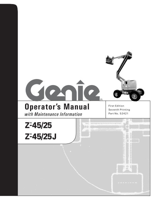
<strong>Operator</strong>’s <strong>Manual</strong><br />
with Maintenance Information<br />
First Edition<br />
Seventh Printing<br />
Part No. 52421
<strong>Operator</strong>'s <strong>Manual</strong><br />
First Edition · Seventh Printing<br />
Important<br />
Read, understand and obey these safety rules and<br />
operating instructions before operating this machine.<br />
Only trained and authorized personnel shall be<br />
permitted to operate this machine. This manual should<br />
be considered a permanent part of your machine and<br />
should remain with the machine at all times. If you<br />
have any questions, call <strong>Genie</strong> Industries.<br />
Contents<br />
Page<br />
Safety ........................................................................ 1<br />
Controls ..................................................................... 7<br />
Pre-operation Inspection........................................... 10<br />
Maintenance ............................................................. 12<br />
Function Tests .......................................................... 16<br />
Workplace Inspection ................................................ 23<br />
Operating Instructions ............................................... 24<br />
Transport Instructions ............................................... 29<br />
Decals ...................................................................... 30<br />
Specifications ........................................................... 32<br />
Contact us:<br />
Internet: http://www.genielift.com<br />
E-mail: techpub@genieind.com<br />
Copyright © 1998 by <strong>Genie</strong> Industries<br />
First Edition: Seventh Printing, May 2002<br />
"<strong>Genie</strong>" and "Z" are registered trademarks of<br />
<strong>Genie</strong> Industries in the U.S.A. and many other<br />
countries.<br />
These machines comply with<br />
ANSI/SIA 92.5-1992.<br />
Printed on recycled paper<br />
Printed in U.S.A.<br />
<strong>Genie</strong> Z-45/25 & <strong>Genie</strong> Z-45/<strong>25J</strong> Part No. 52421
First Edition · Seventh Printing<br />
<strong>Operator</strong>'s <strong>Manual</strong><br />
Safety Rules<br />
Danger<br />
Failure to obey the instructions and<br />
safety rules in this manual will result<br />
in death or serious injury.<br />
Do Not Operate Unless:<br />
You learn and practice the principles of safe<br />
machine operation contained in this operator's<br />
manual.<br />
1 Avoid hazardous situations.<br />
Know and understand the safety rules before<br />
going on to the next section.<br />
2 Always perform a pre-operation inspection.<br />
3 Always perform function tests prior to use.<br />
4 Inspect the workplace.<br />
5 Only use the machine as it was intended.<br />
You read, understand and obey:<br />
Manufacturer's instructions and safety<br />
rules—safety and operator's manuals<br />
and machine decals<br />
employer's safety rules and worksite<br />
regulations<br />
applicable governmental regulations<br />
You are properly trained to safely operate the<br />
machine.<br />
Part No. 52421 <strong>Genie</strong> Z-45/25 & <strong>Genie</strong> Z-45/<strong>25J</strong> 1
<strong>Operator</strong>'s <strong>Manual</strong><br />
First Edition · Seventh Printing<br />
SAFETY RULES<br />
Electrocution Hazards<br />
This machine is not electrically insulated and will<br />
not provide protection from contact with or<br />
proximity to electrical current.<br />
Tip-over Hazards<br />
Occupants and equipment shall not exceed the<br />
maximum platform capacity.<br />
Maximum platform capacity 500 lbs 227 kg<br />
Maximum occupants 2<br />
Maintain safe distances from electrical power lines<br />
and apparatus in accordance with applicable<br />
governmental regulations and the following chart.<br />
Voltage<br />
Phase to Phase<br />
Minimum Safe<br />
Approach Distance<br />
Feet Meters<br />
0 to 300V Avoid Contact<br />
300V to 50KV 10 3.1<br />
50KV to 200KV 15 4.6<br />
200KV to 350KV 20 6.1<br />
350KV to 500KV 25 7.6<br />
500KV to 750KV 35 10.7<br />
750KV to 1000KV 45 13.7<br />
Allow for platform movement, electrical line sway or<br />
sag and beware of strong or gusty winds.<br />
Keep away from the machine if it contacts<br />
energized power lines. Personnel on the ground or<br />
in the platform must not touch or operate the<br />
machine until energized power lines are shut off.<br />
Do not use the machine as a ground for welding.<br />
Do not raise or extend the boom unless the<br />
machine is on a firm, level surface.<br />
Do not depend on the tilt alarm as a level indicator.<br />
The tilt alarm sounds in the platform only when the<br />
machine is on a severe slope.<br />
If the tilt alarm sounds:<br />
Do not extend, rotate or raise the boom above<br />
horizontal. Move the machine to a firm, level<br />
surface before raising the platform. If the tilt alarm<br />
sounds when the platform is raised, use extreme<br />
caution to retract the boom and lower the platform.<br />
Do not rotate the boom while lowering. Move the<br />
machine to a firm, level surface before raising the<br />
platform.<br />
Do not use the platform controls to free a platform<br />
that is caught, snagged or otherwise prevented<br />
from normal motion by an adjacent structure. All<br />
personnel must be removed from the platform<br />
before attempting to free the platform using the<br />
ground controls.<br />
Do not alter or disable the limit switch(es).<br />
2 <strong>Genie</strong> Z-45/25 & <strong>Genie</strong> Z-45/<strong>25J</strong> Part No. 52421
First Edition · Seventh Printing<br />
<strong>Operator</strong>'s <strong>Manual</strong><br />
SAFETY RULES<br />
Do not operate the machine in strong or gusty<br />
winds. Do not increase the surface area of the<br />
platform or the load. Increasing the area exposed to<br />
the wind will decrease machine stability.<br />
Do not modify or alter an aerial work platform.<br />
Mounting attachments for holding tools or other<br />
materials onto the platform, toeboards or guard rail<br />
system can increase the weight in the platform and<br />
the surface area of the platform or the load.<br />
Do not place or attach overhanging loads to any<br />
part of this machine.<br />
Use extreme care and slow speeds while driving<br />
the machine in stowed position across uneven<br />
terrain, debris, unstable or slippery surfaces and<br />
near holes and drop-offs.<br />
Do not drive the machine on or near uneven<br />
terrain, unstable surfaces or other hazardous<br />
conditions with the boom raised or extended.<br />
Do not push off or pull toward any object outside<br />
of the platform.<br />
Maximum allowable<br />
side force - ANSI & CSA<br />
Maximum allowable<br />
side force - CE<br />
Do not alter or disable<br />
machine components<br />
that in any way affect<br />
safety and stability.<br />
150 lbs<br />
667 N<br />
90 lbs<br />
400 N<br />
Do not place ladders or scaffolds in the platform or<br />
against any part of this machine.<br />
Do not use the machine on a moving or mobile<br />
surface or vehicle.<br />
Be sure all tires are in good condition, air-filled tires<br />
are properly inflated and lug nuts are properly<br />
tightened.<br />
Z-45/25 & Z-45/<strong>25J</strong> Narrow Base Models: Do not<br />
use air-filled tires. These machines are equipped<br />
with foam-filled tires. Wheel weight and proper<br />
counterweight configuration are critical to stability.<br />
Do not replace items<br />
critical to machine<br />
stability with items of<br />
different weight or<br />
specification.<br />
Part No. 52421 <strong>Genie</strong> Z-45/25 & <strong>Genie</strong> Z-45/<strong>25J</strong> 3
<strong>Operator</strong>'s <strong>Manual</strong><br />
First Edition · Seventh Printing<br />
SAFETY RULES<br />
Do not use the machine as a crane.<br />
Do not push the machine or other objects with the<br />
boom.<br />
Do not contact adjacent structures with the boom.<br />
Do not tie the boom or platform to adjacent<br />
structures.<br />
Do not place loads outside the platform perimeter.<br />
Fall Hazards<br />
Occupants must wear a<br />
safety belt or harness in<br />
accordance with<br />
governmental regulations.<br />
Attach the lanyard to the<br />
anchor provided in the<br />
platform.<br />
Bodily Injury Hazard<br />
Do not operate the machine with a hydraulic oil or<br />
air leak. An air leak or hydraulic leak can penetrate<br />
and/or burn skin.<br />
Always operate the machine in a well-ventilated<br />
area to avoid carbon monoxide poisoning.<br />
Collision Hazards<br />
Be aware of limited sight<br />
distance and blind spots<br />
when driving or operating.<br />
Be aware of boom position when rotating the<br />
turntable.<br />
Check the work area for overhead obstructions or<br />
other possible hazards.<br />
It is recommended that operators wear an approved<br />
hard hat when operating the machine.<br />
Do not sit, stand or climb on the platform guard<br />
rails. Maintain a firm footing on the platform floor<br />
at all times.<br />
Be aware of crushing hazard when grasping the<br />
platform guard rail.<br />
Observe and use color-coded direction arrows on<br />
the platform controls and drive chassis for drive<br />
and steer functions.<br />
Do not climb down from the platform when raised.<br />
Keep the platform floor clear of debris.<br />
Lower the platform entry mid-rail or close the entry<br />
gate before operating.<br />
4 <strong>Genie</strong> Z-45/25 & <strong>Genie</strong> Z-45/<strong>25J</strong> Part No. 52421
First Edition · Seventh Printing<br />
<strong>Operator</strong>'s <strong>Manual</strong><br />
SAFETY RULES<br />
Do not lower the boom unless the area below is<br />
clear of personnel and obstructions.<br />
Limit travel speed according to condition of ground<br />
surface, congestion, slope, location of personnel,<br />
and any other factors which may cause collision.<br />
Do not operate a boom in the path of any crane<br />
unless the controls of the crane have been locked<br />
out and/or precautions have been taken to prevent<br />
any potential collision.<br />
No stunt driving or horseplay while operating a<br />
machine.<br />
Explosion and Fire Hazards<br />
Do not start the engine if you smell or detect liquid<br />
petroleum gas (LPG), gasoline, diesel fuel or other<br />
explosive substances.<br />
Do not refuel the machine with the engine running.<br />
Refuel the machine and charge the battery only in<br />
an open, well-ventilated area away from sparks,<br />
flames and lighted tobacco.<br />
Do not operate the machine in hazardous locations<br />
or locations where potentially flammable or<br />
explosive gases or particles may be present.<br />
Damaged Machine Hazards<br />
Do not use a damaged or malfunctioning machine.<br />
Conduct a thorough pre-operation inspection of the<br />
machine and test all functions before each work<br />
shift. Immediately tag and remove from service a<br />
damaged or malfunctioning machine.<br />
Be sure all maintenance has been performed as<br />
specified in this manual and the <strong>Genie</strong> Z-45/25 &<br />
<strong>Genie</strong> Z-45/<strong>25J</strong> Service <strong>Manual</strong>.<br />
Be sure all decals are in place and legible.<br />
Be sure operator’s, safety and responsibilities<br />
manuals are complete, legible and in the storage<br />
container located on the platform.<br />
Battery Safety<br />
Burn Hazards<br />
Batteries contain acid. Always wear protective<br />
clothing and eyewear when working with batteries.<br />
Avoid spilling or contacting battery acid. Neutralize<br />
battery acid spills with baking soda and water.<br />
Explosion Hazard<br />
Keep sparks, flames and lighted tobacco away<br />
from batteries. Batteries emit explosive gas.<br />
Electrocution Hazard<br />
Avoid contact with electrical terminals.<br />
Component Damage Hazards<br />
Do not use any battery or charger greater than 12V<br />
to jump-start the engine.<br />
Do not use the machine as a ground for welding.<br />
Be sure the hydraulic shutoff valves (located by<br />
hydraulic tank) are open before starting the engine.<br />
Part No. 52421 <strong>Genie</strong> Z-45/25 & <strong>Genie</strong> Z-45/<strong>25J</strong> 5
<strong>Operator</strong>'s <strong>Manual</strong><br />
First Edition · Seventh Printing<br />
SAFETY RULES<br />
Decal Legend<br />
<strong>Genie</strong> product decals use symbols, color coding<br />
and signal words to identify the following:<br />
Safety alert symbol—used to alert<br />
personnel to potential personal<br />
injury hazards. Obey all safety<br />
messages that follow this symbol<br />
to avoid possible injury or death.<br />
Red—used to indicate the<br />
presence of an imminently<br />
hazardous situation which, if not<br />
avoided, will result in death or<br />
serious injury.<br />
Orange—used to indicate the<br />
presence of a potentially<br />
hazardous situation which, if not<br />
avoided, could result in death or<br />
serious injury.<br />
Yellow with safety alert symbol—<br />
used to indicate the presence of a<br />
potentially hazardous situation<br />
which, if not avoided, may cause<br />
minor or moderate injury.<br />
Yellow without safety alert<br />
symbol—used to indicate the<br />
presence of a potentially<br />
hazardous situation which, if not<br />
avoided, may result in property<br />
damage.<br />
Green—used to indicate operation<br />
or maintenance information.<br />
6 <strong>Genie</strong> Z-45/25 & <strong>Genie</strong> Z-45/<strong>25J</strong> Part No. 52421
First Edition · Seventh Printing<br />
<strong>Operator</strong>'s <strong>Manual</strong><br />
Controls<br />
6<br />
7<br />
8<br />
9<br />
5<br />
4<br />
3<br />
2<br />
10<br />
11<br />
12<br />
1<br />
13<br />
19<br />
18<br />
17<br />
16<br />
15<br />
14<br />
Ground Control Panel<br />
1 Platform rotate switch<br />
2 Turntable rotate switch<br />
3 Primary boom up/down switch<br />
4 Primary boom extend/retract switch<br />
5 Gasoline/LPG models: Fuel select switch<br />
6 Auxiliary power switch<br />
7 Key switch for platform/off/ground selection<br />
8 Red Emergency Stop button<br />
9 Gasoline/LPG models: Check engine light<br />
Diesel models: Oil pressure light<br />
10 Hour meter<br />
11 Diesel models: Water temperature light<br />
12 Gasoline/LPG models: Choke switch<br />
Diesel models: Glow plug switch (option)<br />
13 Function enable switch<br />
14 Engine start switch<br />
15 15A breaker for engine electrical circuits<br />
16 Secondary boom up/down switch<br />
17 15A breaker for control electrical circuits<br />
18 Z-45/<strong>25J</strong> models only: Jib boom up/down switch<br />
19 Platform level switch<br />
Part No. 52421 <strong>Genie</strong> Z-45/25 & <strong>Genie</strong> Z-45/<strong>25J</strong> 7
<strong>Operator</strong>'s <strong>Manual</strong><br />
First Edition · Seventh Printing<br />
CONTROLS<br />
1 2<br />
3<br />
4 5 6<br />
18 13<br />
17<br />
16<br />
Platform Control Panel<br />
1 Horn button<br />
2 Platform level switch<br />
3 Platform rotate switch<br />
4 Z-45/<strong>25J</strong> models only: Jib boom up/down switch<br />
5 Auxiliary power switch<br />
6 Drive speed select switch<br />
7 Glow plug switch<br />
8 Engine start switch<br />
9 Engine idle (rpm) select switch<br />
10 Gasoline/LPG models: Gasoline/LPG<br />
select switch<br />
8 <strong>Genie</strong> Z-45/25 & <strong>Genie</strong> Z-45/<strong>25J</strong> Part No. 52421
First Edition · Seventh Printing<br />
<strong>Operator</strong>'s <strong>Manual</strong><br />
CONTROLS<br />
7 8 9 10<br />
11<br />
15 14<br />
13<br />
13<br />
12<br />
11 Red Emergency Stop button<br />
12 Dual axis proportional control handle for drive<br />
and steer functions<br />
OR Proportional control handle for drive function<br />
and thumb rocker for steer function<br />
13 used for optional equipment<br />
14 Drive enable indicator light<br />
15 Drive enable switch<br />
16 Proportional control handle for secondary boom<br />
up/down function<br />
17 Primary boom extend/retract switch<br />
18 Dual axis proportional control handle for primary<br />
boom up/down and turntable rotate<br />
left/right functions<br />
Part No. 52421 <strong>Genie</strong> Z-45/25 & <strong>Genie</strong> Z-45/<strong>25J</strong> 9
<strong>Operator</strong>'s <strong>Manual</strong><br />
First Edition · Seventh Printing<br />
Pre-operation Inspection<br />
Fundamentals<br />
It is the responsibility of the operator to perform a<br />
Pre-operation Inspection and routine maintenance.<br />
Do Not Operate Unless:<br />
You learn and practice the principles of safe<br />
machine operation contained in this operator's<br />
manual.<br />
1 Avoid hazardous situations.<br />
2 Always perform a pre-operation<br />
inspection.<br />
Know and understand the pre-operation<br />
inspection before going on to the next<br />
section.<br />
3 Always perform function tests prior to use.<br />
4 Inspect the workplace.<br />
5 Only use the machine as it was intended.<br />
The Pre-operation Inspection is a visual inspection<br />
performed by the operator prior to each work shift.<br />
The inspection is designed to discover if anything<br />
is apparently wrong with a machine before the<br />
operator performs the function tests.<br />
The Pre-operation inspection also serves to<br />
determine if routine maintenance procedures are<br />
required. Only routine maintenance items specified<br />
in this manual may be performed by the operator.<br />
Refer to the list on the next page and check each<br />
of the items and locations for modifications,<br />
damage or loose or missing parts.<br />
A damaged or modified machine must never be<br />
used. If damage or any variation from factory<br />
delivered condition is discovered, the machine<br />
must be tagged and removed from service.<br />
Repairs to the machine may only be made by a<br />
qualified service technician, according to the<br />
manufacturer's specifications. After repairs are<br />
completed, the operator must perform a<br />
pre-operation inspection again before going on to<br />
the function tests.<br />
Scheduled maintenance inspections shall be<br />
performed by qualified service technicians,<br />
according to the manufacturer's specifications and<br />
the requirements listed in the responsibilities<br />
manual.<br />
10 <strong>Genie</strong> Z-45/25 & <strong>Genie</strong> Z-45/<strong>25J</strong> Part No. 52421
First Edition · Seventh Printing<br />
<strong>Operator</strong>'s <strong>Manual</strong><br />
PRE-OPERATION INSPECTION<br />
Pre-operation Inspection<br />
o Be sure that the operator’s, safety and<br />
responsibilities manuals are complete, legible<br />
and in the storage container located in the<br />
platform.<br />
o Be sure that all decals are legible and in place.<br />
See Decals section.<br />
o Check for engine oil leaks and proper oil level.<br />
Add oil if needed. See Maintenance section.<br />
o Check for hydraulic oil leaks and proper oil level.<br />
Add oil if needed. See Maintenance section.<br />
o Check for engine coolant leaks and proper level<br />
of coolant. Add coolant if needed. See<br />
Maintenance section.<br />
o Check for battery fluid leaks and proper fluid<br />
level. Add distilled water if needed. See<br />
Maintenance section.<br />
o Z-45/25 RT and Z-45/<strong>25J</strong> RT models: Check for<br />
proper tire pressure. Add air if needed. See<br />
Maintenance section.<br />
Check the following components or areas for<br />
damage and improperly installed, loose or missing<br />
parts:<br />
o Engine and related components<br />
o Limit switches and horn<br />
o Alarms and beacons (if equipped)<br />
o Nuts, bolts and other fasteners<br />
o Platform entry mid-rail or gate<br />
Check entire machine for:<br />
o Crack in welds or structural components<br />
o Dents or damage to machine<br />
o Be sure that all structural and other critical<br />
components are present and all associated<br />
fasteners and pins are in place and properly<br />
tightened.<br />
o After you complete your inspection, be sure that<br />
all compartment covers are in place and<br />
latched.<br />
o Electrical components, wiring and<br />
electrical cables<br />
o Hydraulic hoses, fittings, cylinders and<br />
manifolds<br />
o Fuel and hydraulic tanks<br />
o Drive and turntable motors and drive hubs<br />
o Boom wear pads<br />
o Tires and wheels<br />
Part No. 52421 <strong>Genie</strong> Z-45/25 & <strong>Genie</strong> Z-45/<strong>25J</strong> 11
<strong>Operator</strong>'s <strong>Manual</strong><br />
First Edition · Seventh Printing<br />
Maintenance<br />
Check the Engine Oil Level<br />
Observe and Obey:<br />
Only routine maintenance items specified in this<br />
manual shall be performed by the operator.<br />
Scheduled maintenance inspections shall be<br />
completed by qualified service technicians,<br />
according to the manufacturer's specifications<br />
and the requirements specified in the<br />
responsibilities manual.<br />
Maintenance Symbols Legend<br />
The following symbols have been<br />
used in this manual to help<br />
communicate the intent of the<br />
instructions. When one or more of<br />
the symbols appear at the<br />
beginning of a maintenance<br />
procedure, it conveys the meaning<br />
below.<br />
Indicates that tools will be required to<br />
perform this procedure.<br />
Indicates that new parts will be<br />
required to perform this procedure.<br />
Maintaining the proper engine oil level is essential<br />
to good engine performance and service life.<br />
Operating the machine with an improper oil level<br />
can damage engine components.<br />
1 Check the oil dipstick.<br />
Ford models:<br />
Check the oil level with the<br />
engine off.<br />
Result: The oil level should be between the ADD<br />
and SAFE marks. Add oil as needed.<br />
Deutz models:<br />
Result: The oil level should be within the two<br />
marks on the dipstick. Add oil as needed.<br />
Perkins Models:<br />
Result: The oil level should be within the two<br />
notches on the dipstick.<br />
Ford LRG-425 EFI Engine<br />
Oil viscosity requirements<br />
below 60°F / 15.5°C 5W-30<br />
-10° to 90°F / -23° to 32°C 5W-30<br />
above -10°F / -23°C 5W-30<br />
above 25°F / -4°C 10W-30<br />
Use oils meeting API classification SH or SG.<br />
Units ship with 10-40 CC/SG.<br />
Indicates that a cold engine is required<br />
before performing this procedure.<br />
12 <strong>Genie</strong> Z-45/25 & <strong>Genie</strong> Z-45/<strong>25J</strong> Part No. 52421
First Edition · Seventh Printing<br />
<strong>Operator</strong>'s <strong>Manual</strong><br />
MAINTENANCE<br />
Deutz Engine F3L 1011F<br />
Oil viscosity requirements<br />
Check the Hydraulic Oil Level<br />
below 60°F / 15.5°C (synthetic) 5W-30<br />
-10°F to 90°F / -23°C to 32°C 10W-40<br />
above -4°F / -34°C 15W-40<br />
Engine oil should have properties of API classification<br />
CC/SE, CD/SE, SF/CC or SF/CD grades.<br />
Units ship with 10-40 CC/SG.<br />
Perkins Engine 104-22<br />
Oil viscosity requirements<br />
below 60°F / 15.5°C 5W-20<br />
-10° to 90°F / -23° to 32°C 10W-30<br />
above -10°F / -23°C 15W-40<br />
above 25°F / -4°C 20W-50<br />
Maintaining the hydraulic oil at the proper level is<br />
essential to machine operation. Improper hydraulic<br />
oil levels can damage hydraulic components. Daily<br />
checks allow the inspector to identify changes in oil<br />
level that might indicate the presence of hydraulic<br />
system problems.<br />
1 Be sure that the boom is in the stowed position,<br />
then visually inspect the sight gauge located on<br />
the side of the hydraulic oil tank.<br />
Result: The hydraulic oil level should be within<br />
the top 2 inches / 5 cm of the sight gauge.<br />
2 Add oil as needed.<br />
Engine oil should have properties of API classification<br />
CC/SE, CD/SE, SF/CC or SF/CD grades.<br />
Units ship with 10-40 CC/SG.<br />
Hydraulic oil specifications<br />
Hydraulic oil type<br />
Dexron equivalent<br />
Part No. 52421 <strong>Genie</strong> Z-45/25 & <strong>Genie</strong> Z-45/<strong>25J</strong> 13
<strong>Operator</strong>'s <strong>Manual</strong><br />
First Edition · Seventh Printing<br />
MAINTENANCE<br />
Check the Engine Coolant Level -<br />
Ford and Perkins Models<br />
Check the Batteries<br />
Maintaining the engine coolant at the proper level<br />
is essential to engine service life. Improper coolant<br />
level will affect the engine's cooling capability and<br />
damage engine components. Daily checks will<br />
allow the inspector to identify changes in coolant<br />
level that might indicate cooling system problems.<br />
Burn hazard. Beware of hot<br />
engine parts and coolant. Contact<br />
with hot engine parts and/or<br />
coolant may cause severe burns.<br />
1 Check the fluid level in the coolant recovery<br />
tank. Add fluid as needed.<br />
Result: The fluid level should be at the<br />
FULL mark.<br />
Do not remove the radiator cap.<br />
Proper battery condition is essential to good engine<br />
performance and operational safety. Improper fluid<br />
levels or damaged cables and connections can<br />
result in engine component damage and hazardous<br />
conditions.<br />
Electrocution hazard. Contact with<br />
hot or live circuits may result in<br />
death or serious injury. Remove all<br />
rings, watches and other jewelry.<br />
Bodily injury hazard. Batteries<br />
contain acid. Avoid spilling or<br />
contacting battery acid. Neutralize<br />
battery acid spills with baking soda<br />
and water.<br />
1 Put on protective clothing and eye wear.<br />
2 Be sure that the battery cable connections are<br />
tight and free of corrosion.<br />
3 Be sure that the battery hold-down bracket is<br />
secure.<br />
4 Remove the battery vent caps.<br />
5 Check the battery acid level. If needed,<br />
replenish with distilled water to the bottom of<br />
the battery fill tube. Do not overfill.<br />
6 Install the vent caps.<br />
Adding terminal protectors and a<br />
corrosion preventative sealant will<br />
help eliminate corrosion on the<br />
battery terminals and cables.<br />
14 <strong>Genie</strong> Z-45/25 & <strong>Genie</strong> Z-45/<strong>25J</strong> Part No. 52421
First Edition · Seventh Printing<br />
<strong>Operator</strong>'s <strong>Manual</strong><br />
MAINTENANCE<br />
Check the Tire Pressure<br />
Bodily injury hazard. An overinflated<br />
tire can explode, which can<br />
result in death or serious injury.<br />
Tip-over hazard. Do not use<br />
temporary flat tire repair products.<br />
This procedure does not need<br />
to be performed on machines<br />
equipped with foam-filled<br />
tires.<br />
To safeguard maximum stability, achieve<br />
optimum machine handling and minimize tire<br />
wear, it is essential to maintain proper pressure<br />
in all air-filled tires.<br />
Scheduled Maintenance<br />
Maintenance performed quarterly, annually and<br />
every two years must be completed by a person<br />
trained and qualified to perform maintenance on this<br />
machine according to the procedures found in the<br />
service manual for this machine.<br />
Machines that have been out of service for more<br />
than three months must receive the quarterly<br />
inspection before they are put back into service.<br />
1 Check each tire with an air pressure gauge and<br />
add air as needed.<br />
Tire specifications 2WD Models 4WD Models<br />
Narrow base models<br />
Industrial tire Foam Filled Only<br />
Standard base models<br />
Rough terrain tire 14-17.5 NHS 14-17.5 NHS<br />
45 psi / 3.1 bar 45 psi / 3.1 bar<br />
Part No. 52421 <strong>Genie</strong> Z-45/25 & <strong>Genie</strong> Z-45/<strong>25J</strong> 15
<strong>Operator</strong>'s <strong>Manual</strong><br />
First Edition · Seventh Printing<br />
Function Tests<br />
Fundamentals<br />
The Function Tests are designed to discover any<br />
malfunctions before the machine is put into<br />
service. The operator must follow the step-by-step<br />
instructions to test all machine functions.<br />
Do Not Operate Unless:<br />
You learn and practice the principles of safe<br />
machine operation contained in this operator's<br />
manual.<br />
1 Avoid hazardous situations.<br />
2 Always perform a pre-operation<br />
inspection.<br />
3 Always perform function tests prior to<br />
use.<br />
Know and understand the function tests<br />
before going on to the next section.<br />
4 Inspect the workplace.<br />
5 Only use the machine as it was intended.<br />
A malfunctioning machine must never be used. If<br />
malfunctions are discovered, the machine must be<br />
tagged and removed from service. Repairs to the<br />
machine may only be made by a qualified service<br />
technician, according to the manufacturer's<br />
specifications.<br />
After repairs are completed, the operator must<br />
perform a pre-operation inspection and function<br />
tests again before putting the machine into service.<br />
Symbol Legend<br />
Indicates that a specific result is expected after<br />
performing a series of steps.<br />
16 <strong>Genie</strong> Z-45/25 & <strong>Genie</strong> Z-45/<strong>25J</strong> Part No. 52421
First Edition · Seventh Printing<br />
<strong>Operator</strong>'s <strong>Manual</strong><br />
FUNCTION TESTS<br />
1 Select a test area that is firm, level and free of<br />
obstruction.<br />
At the Ground Controls<br />
2 Turn the key switch to ground control.<br />
3 Pull out the red Emergency Stop button to<br />
the on position.<br />
Result: Beacon (if equipped) should flash.<br />
4 Start the engine. See Operating Instruction<br />
section.<br />
Test Emergency Stop<br />
5 Push in the red Emergency Stop button to the<br />
off position.<br />
Result: The engine will shut off after 2 to 3<br />
seconds.<br />
6 Pull out the red Emergency Stop button to<br />
the on position and restart the engine.<br />
Test the Machine Functions<br />
7 Do not hold the function enable switch to either<br />
side. Attempt to activate each boom and<br />
platform function toggle switch.<br />
Result: All boom and platform functions should<br />
not operate.<br />
8 Hold the function enable switch to either side<br />
and activate each boom and platform function<br />
toggle switch.<br />
Result: All boom and platform functions should<br />
operate through a full cycle. The descent alarm<br />
(if equipped) should sound while the boom is<br />
lowering.<br />
Machines equipped with Platform Level Control<br />
Disable Function: The platform level toggle switch<br />
will not operate when the primary boom is raised<br />
past the drive speed limit switch.<br />
Test the Tilt Sensor<br />
9 Pull out the platform red<br />
Emergency Stop button to<br />
the on position. Turn the<br />
key switch to platform<br />
control.<br />
10 Open the engine side<br />
turntable cover and locate<br />
the tilt sensor to the right of<br />
the hydraulic pump.<br />
11 Press down one side of the tilt sensor.<br />
Result: The alarm, located in the platform,<br />
should sound.<br />
Test Auxiliary Controls<br />
12 Turn the key switch to ground control and shut<br />
the engine off.<br />
13 Pull out the red Emergency Stop button to the<br />
on position.<br />
14 Simultaneously hold the auxiliary power switch<br />
on and activate each boom function toggle<br />
switch.<br />
Note: To conserve battery power, test each<br />
function through a partial cycle.<br />
Result: All boom functions should operate.<br />
Part No. 52421 <strong>Genie</strong> Z-45/25 & <strong>Genie</strong> Z-45/<strong>25J</strong> 17
<strong>Operator</strong>'s <strong>Manual</strong><br />
First Edition · Seventh Printing<br />
FUNCTION TESTS<br />
At the Platform Controls<br />
Test Emergency Stop<br />
15 Turn the key switch to platform control and<br />
restart the engine.<br />
16 Push in the platform red Emergency Stop<br />
button to the off position.<br />
Result: The engine will shut off after 2 or 3<br />
seconds.<br />
17 Pull out the red Emergency Stop button and<br />
restart the engine.<br />
Test the Horn<br />
18 Push the horn button.<br />
Result: The horn should sound.<br />
Test the Foot Switch<br />
19 Push in the platform red Emergency Stop button<br />
to the off position.<br />
20 Pull out the red Emergency Stop button to<br />
the on position but do not start the engine.<br />
21 Press down the foot switch and attempt to start<br />
the engine by moving the start toggle switch to<br />
either side.<br />
Result: The engine should not start.<br />
22 Do not press down the foot switch and restart<br />
the engine.<br />
Result: The engine should start.<br />
23 Move the lift/drive select switch to the lift<br />
position (if equipped).<br />
24 Do not press down the foot switch and test each<br />
machine function.<br />
Result: The machine functions should not<br />
operate.<br />
Test Machine Functions<br />
25 Press down the foot switch.<br />
26 Activate each machine function control handle<br />
or toggle switch.<br />
Result: All boom/platform functions should<br />
operate through a full cycle.<br />
Machines equipped with Platform Level Control<br />
Disable Function: The platform level toggle switch<br />
will not operate when the primary boom is raised<br />
past the drive speed limit switch.<br />
Test the Steering<br />
27 Move the lift/drive select switch to the drive<br />
position (if equipped).<br />
28 Press down the foot switch.<br />
29 Press the thumb rocker switch on top of the<br />
drive control handle in the direction indicated by<br />
the blue triangle on the control panel OR slowly<br />
move the control handle in the direction<br />
indicated by the blue triangle.<br />
Result: The steer wheels should turn in the<br />
direction that the blue triangles point on the<br />
drive chassis.<br />
30 Press the thumb rocker switch on top of the<br />
drive control handle in the direction indicated by<br />
the yellow triangle on the control panel OR<br />
slowly move the control handle in the direction<br />
indicated by the yellow triangle.<br />
Result: The steer wheels should turn in the<br />
direction that the yellow triangles point on the<br />
drive chassis.<br />
18 <strong>Genie</strong> Z-45/25 & <strong>Genie</strong> Z-45/<strong>25J</strong> Part No. 52421
First Edition · Seventh Printing<br />
<strong>Operator</strong>'s <strong>Manual</strong><br />
FUNCTION TESTS<br />
Test Drive and Braking<br />
31 Press down the foot switch.<br />
32 Slowly move the drive control handle in the<br />
direction indicated by the blue arrow on the<br />
control panel until the machine begins to move,<br />
then return the handle to the center position.<br />
Result: The machine should move in the<br />
direction that the blue arrow points on the drive<br />
chassis, then come to an abrupt stop.<br />
33 Slowly move the drive control handle in the<br />
direction indicated by the yellow arrow on the<br />
control panel until the machine begins to move,<br />
then return the handle to the center position.<br />
Result: The machine should move in the<br />
direction that the yellow arrow points on the<br />
drive chassis, then come to an abrupt stop.<br />
Note: The brakes must be able to hold the machine<br />
on any slope it is able to climb.<br />
Test the Drive Enable System<br />
34 Move the lift/drive select switch to the lift<br />
position (if equipped).<br />
35 Press down the foot switch and lower the boom<br />
to the stowed position.<br />
36 Rotate the turntable until the<br />
primary boom moves past<br />
one of the non-steer wheels.<br />
Result: The drive enable<br />
indicator light should come<br />
on and remain on while the<br />
boom is anywhere in the<br />
range shown.<br />
37 Move the lift/drive select<br />
switch to the drive position (if equipped).<br />
38 Move the drive control handle off center.<br />
Result: The drive function should not operate.<br />
39 Move and hold the drive enable toggle switch to<br />
either side and slowly move the drive control<br />
handle off center.<br />
Result: The drive function should operate.<br />
Note: When the drive enable system is in use, the<br />
machine may drive in the opposite direction that the<br />
drive and steer control handle is moved.<br />
Use the color-coded direction<br />
arrows on the platform<br />
controls and the drive chassis<br />
to identify the direction of<br />
travel.<br />
Blue<br />
Yellow<br />
Part No. 52421 <strong>Genie</strong> Z-45/25 & <strong>Genie</strong> Z-45/<strong>25J</strong> 19
<strong>Operator</strong>'s <strong>Manual</strong><br />
First Edition · Seventh Printing<br />
FUNCTION TESTS<br />
Test Limited Drive Speed<br />
Z-45/25 & Z-45/<strong>25J</strong> Standard Base Models<br />
ANSI and CSA Z-45/25 & Z-45/<strong>25J</strong> Narrow<br />
Base Models before serial number 19081<br />
40 Move the lift/drive select switch to the lift<br />
position (if equipped).<br />
41 Press down the foot switch.<br />
42 Raise the primary boom approximately<br />
2 feet / 61 cm.<br />
43 Move the lift/drive select switch to the drive<br />
position (if equipped).<br />
44 Slowly move the drive control handle to the full<br />
drive position.<br />
Result: The maximum achievable drive speed<br />
with the primary boom raised should not exceed<br />
1 foot / 30 cm per second.<br />
45 Move the lift/drive select switch to the lift<br />
position (if equipped).<br />
46 Lower the primary boom to the stowed position.<br />
47 Raise the secondary boom approximately<br />
2 feet / 61 cm.<br />
48 Move the lift/drive select switch to the drive<br />
position (if equipped).<br />
49 Slowly move the drive control handle to the full<br />
drive position.<br />
Result: The maximum achievable drive speed<br />
with the secondary boom raised should not<br />
exceed 1 foot / 30 cm per second.<br />
50 Move the lift/drive select switch to the lift<br />
position (if equipped).<br />
51 Lower the secondary boom to the stowed<br />
position.<br />
52 Extend the primary boom approximately<br />
1 foot / 30 cm.<br />
53 Move the lift/drive select switch to the drive<br />
position (if equipped).<br />
54 Slowly move the drive control handle to the full<br />
drive position.<br />
Result: The maximum achievable drive speed<br />
with the primary boom extended should not<br />
exceed 1 foot / 30 cm per second.<br />
55 Move the lift/drive select switch to the lift<br />
position (if equipped).<br />
56 Retract the boom to the stowed position.<br />
If the drive speed with the primary boom raised, the<br />
secondary boom raised or the primary boom<br />
extended exceeds 1 foot / 30 cm per second,<br />
immediately tag and remove the machine from<br />
service.<br />
Test Limited Drive Speed<br />
CE Z-45/25 & Z-45/<strong>25J</strong> Narrow Base Models<br />
before serial number 19081<br />
All Z-45/25 & Z-45/<strong>25J</strong> Narrow Base Models<br />
after serial number 19080<br />
40 Move the lift/drive select switch to the lift<br />
position (if equipped).<br />
41 Press down the foot switch.<br />
20 <strong>Genie</strong> Z-45/25 & <strong>Genie</strong> Z-45/<strong>25J</strong> Part No. 52421
First Edition · Seventh Printing<br />
<strong>Operator</strong>'s <strong>Manual</strong><br />
FUNCTION TESTS<br />
42 Raise the primary boom approximately<br />
2 feet / 61 cm.<br />
43 Move the lift/drive select switch to the drive<br />
position (if equipped).<br />
44 Slowly move the drive control handle to the full<br />
drive position.<br />
Result: The maximum achievable drive speed<br />
with the primary boom raised should not exceed<br />
0.5 foot / 15 cm per second.<br />
45 Move the lift/drive select switch to the lift<br />
position (if equipped).<br />
46 Lower the primary boom to the stowed position.<br />
47 Raise the secondary boom approximately<br />
2 feet / 61 cm.<br />
48 Move the lift/drive select switch to the drive<br />
position (if equipped).<br />
49 Slowly move the drive control handle to the full<br />
drive position.<br />
Result: The maximum achievable drive speed<br />
with the secondary boom raised should not<br />
exceed 0.5 foot / 15 cm per second.<br />
50 Move the lift/drive select switch to the lift<br />
position (if equipped).<br />
51 Lower the secondary boom to the stowed<br />
position.<br />
52 Extend the primary boom approximately<br />
1 foot / 30 cm.<br />
53 Move the lift/drive select switch to the drive<br />
position (if equipped).<br />
54 Slowly move the drive control handle to the full<br />
drive position.<br />
Result: The maximum achievable drive speed<br />
with the primary boom extended should not<br />
exceed 0.5 foot / 15 cm per second.<br />
55 Move the lift/drive select switch to the lift<br />
position (if equipped).<br />
56 Retract the boom to the stowed position.<br />
If the drive speed with the primary boom raised, the<br />
secondary boom raised or the primary boom<br />
extended exceeds 0.5 foot / 15 cm cm per second,<br />
immediately tag and remove the machine from<br />
service.<br />
Test the Oscillate Axle<br />
(oscillating axle-equipped models)<br />
57 Move the lift/drive select switch to the drive<br />
position (if equipped).<br />
58 Start the engine from the platform controls.<br />
59 Drive the right steer tire up onto a 6 inch /<br />
15.2 cm block or curb.<br />
Result: The three remaining tires should stay in<br />
firm contact with the ground.<br />
60 Drive the left steer tire up onto a 6 inch /<br />
15.2 cm block or curb.<br />
Result: The three remaining tires should stay in<br />
firm contact with the ground.<br />
61 Drive both steer tires up onto a 6 inch /<br />
15.2 cm block or curb.<br />
Result: The non-steer tires should stay in firm<br />
contact with the ground.<br />
Part No. 52421 <strong>Genie</strong> Z-45/25 & <strong>Genie</strong> Z-45/<strong>25J</strong> 21
<strong>Operator</strong>'s <strong>Manual</strong><br />
First Edition · Seventh Printing<br />
FUNCTION TESTS<br />
Test Auxiliary Controls<br />
62 Shut the engine off.<br />
63 Pull out the red Emergency Stop button to<br />
the on position.<br />
64 Move the lift/drive select switch to the lift<br />
position (if equipped).<br />
65 Press down the foot switch.<br />
66 Simultaneously hold<br />
the auxiliary power<br />
switch on and<br />
activate each<br />
function control<br />
handle or toggle<br />
switch.<br />
Note: To conserve battery power, test each<br />
function through a partial cycle.<br />
Result: All boom and steer functions should<br />
operate. Drive functions should not operate with<br />
auxiliary power.<br />
Test the Lift/Drive Select Function<br />
(CE models)<br />
Machines with lift/drive select switch:<br />
67 Move the lift/drive select switch to the lift<br />
position.<br />
68 Press down the foot switch.<br />
69 Move the drive control handle off center.<br />
Result: No drive functions should operate.<br />
70 Activate each boom function toggle switch.<br />
Result: All boom functions should operate.<br />
71 Move the lift/drive select switch to the drive<br />
position.<br />
72 Press down the foot switch.<br />
73 Activate each boom function toggle switch.<br />
Result: No boom functions should operate.<br />
74 Move the drive control handle off center.<br />
Result: The drive functions should operate.<br />
75 Repair any malfunctions before operating the<br />
machine.<br />
Machines without lift/drive select switch:<br />
76 Press down the foot switch.<br />
77 Move the drive control handle off center and<br />
activate a boom function toggle switch.<br />
Result: No boom functions should operate. The<br />
machine will move in the direction indicated on<br />
the control panel.<br />
78 Repair any malfunctions before operating the<br />
machine.<br />
22 <strong>Genie</strong> Z-45/25 & <strong>Genie</strong> Z-45/<strong>25J</strong> Part No. 52421
First Edition · Seventh Printing<br />
<strong>Operator</strong>'s <strong>Manual</strong><br />
Workplace Inspection<br />
Workplace Inspection<br />
Be aware of and avoid the following hazardous<br />
situations:<br />
· drop-offs or holes<br />
Do Not Operate Unless:<br />
You learn and practice the principles of safe<br />
machine operation contained in this operator's<br />
manual.<br />
1 Avoid hazardous situations.<br />
2 Always perform a pre-operation<br />
inspection.<br />
3 Always perform function tests prior to use.<br />
4 Inspect the workplace.<br />
Know and understand the workplace<br />
inspection before going on to the next<br />
section.<br />
5 Only use the machine as it was intended.<br />
· bumps, floor obstructions or debris<br />
· overhead obstructions and high voltage<br />
conductors<br />
· hazardous locations<br />
· inadequate surface support to withstand all load<br />
forces imposed by the machine<br />
· wind and weather conditions<br />
· the presence of unauthorized personnel<br />
· other possible unsafe conditions<br />
Fundamentals<br />
The Workplace Inspection helps the operator<br />
determine if the workplace is suitable for safe<br />
machine operation. It should be performed by the<br />
operator prior to moving the machine to the<br />
workplace.<br />
It is the operator's responsibility to read and<br />
remember the workplace hazards, then watch for<br />
and avoid them while moving, setting up and<br />
operating the machine.<br />
Part No. 52421 <strong>Genie</strong> Z-45/25 & <strong>Genie</strong> Z-45/<strong>25J</strong> 23
<strong>Operator</strong>'s <strong>Manual</strong><br />
First Edition · Seventh Printing<br />
Operating Instructions<br />
Fundamentals<br />
Do Not Operate Unless:<br />
You learn and practice the principles of safe<br />
machine operation contained in this operator's<br />
manual.<br />
1 Avoid hazardous situations.<br />
2 Always perform a pre-operation<br />
inspection.<br />
3 Always perform function tests prior to use.<br />
4 Inspect the workplace.<br />
5 Only use the machine as it was intended.<br />
The Operating Instructions section provides<br />
instructions for each aspect of machine operation.<br />
It is the operator's responsibility to follow all the<br />
safety rules and instructions in the operator's,<br />
safety and responsibilities manuals.<br />
Using the machine for anything other than lifting<br />
personnel and tools to an aerial work site is unsafe<br />
and dangerous.<br />
Only trained and authorized personnel should be<br />
permitted to operate a machine. If more than one<br />
operator is expected to use a machine at different<br />
times in the same work shift, they must all be<br />
qualified operators and are all expected to follow all<br />
safety rules and instructions in the operator's,<br />
safety and responsibilities manuals. That means<br />
every new operator should perform a pre-operation<br />
inspection, function tests, and a workplace<br />
inspection before using the machine.<br />
24 <strong>Genie</strong> Z-45/25 & <strong>Genie</strong> Z-45/<strong>25J</strong> Part No. 52421
First Edition · Seventh Printing<br />
<strong>Operator</strong>'s <strong>Manual</strong><br />
OPERATING INSTRUCTIONS<br />
Starting the Engine<br />
1 At the ground controls, turn the key switch to<br />
the desired position.<br />
2 Be sure both ground and platform control red<br />
Emergency Stop buttons are pulled out to the<br />
on position.<br />
3 Gasoline/LPG models: Choose fuel by moving<br />
the fuel select switch to the desired position.<br />
4 Move the engine start toggle<br />
switch to either side. If the engine<br />
fails to start or dies, the restart<br />
delay will disable the start switch<br />
for 3 seconds.<br />
If the engine fails to start after 15 seconds of<br />
cranking, determine the cause and repair any<br />
malfunction. Wait 60 seconds before trying to start<br />
again.<br />
All models: In extreme cold conditions, 20°F / -6°C<br />
and below, warm the engine for 5 minutes to<br />
prevent hydraulic system damage.<br />
Gasoline/LPG models: In extreme cold conditions,<br />
20°F / -6°C and below, the machine should be<br />
started on gasoline, then switched to LPG.<br />
Emergency Stop<br />
Push in either ground or platform red Emergency<br />
Stop button to the off position to stop all functions<br />
and turn the engine off.<br />
Auxiliary Controls<br />
Use auxiliary power if the primary power source<br />
(engine) fails.<br />
1 Turn the key switch to ground or platform<br />
control.<br />
2 Pull out the red Emergency Stop button to the<br />
on position.<br />
3 Move the lift/drive select switch to the lift<br />
position when operating the auxiliary controls<br />
from the platform.<br />
4 Press down the foot switch when operating the<br />
auxiliary controls from the platform.<br />
5 Simultaneously hold auxiliary power switch on<br />
and activate the desired function.<br />
The drive and steer functions will not operate with<br />
auxiliary power.<br />
Operation from Ground<br />
1 Turn the key switch to ground control.<br />
2 Pull out the red Emergency Stop button to<br />
the on position.<br />
3 Gasoline/LPG models: Choose fuel by moving<br />
the fuel select switch to the desired position.<br />
4 Start the engine.<br />
Repair any function that operates when the red<br />
Emergency Stop button is pushed in.<br />
Selecting and operating the ground controls will<br />
override the platform red Emergency Stop button.<br />
Part No. 52421 <strong>Genie</strong> Z-45/25 & <strong>Genie</strong> Z-45/<strong>25J</strong> 25
<strong>Operator</strong>'s <strong>Manual</strong><br />
First Edition · Seventh Printing<br />
OPERATING INSTRUCTIONS<br />
To Position Platform<br />
1 Hold the function enable switch to either side.<br />
2 Move the appropriate toggle switch according to<br />
the markings on the control panel.<br />
Drive and steer functions are not available from the<br />
ground controls.<br />
Machines equipped with Platform Level Control<br />
Disable Function: The platform level toggle switch<br />
will not operate when the primary boom is raised<br />
past the drive speed limit switch.<br />
Operation from Platform<br />
1 Turn the key switch to platform control.<br />
2 Pull out both ground and platform red<br />
Emergency Stop buttons to the on position.<br />
3 Gasoline/LPG models: Choose fuel by moving<br />
the fuel select switch to the desired position.<br />
4 Start the engine. Do not press down the foot<br />
switch when starting the engine.<br />
To Position Platform<br />
1 Move the lift/drive select switch to the lift<br />
position (if equipped).<br />
2 Press down the foot switch.<br />
3 Slowly move the appropriate function control<br />
handle or toggle switch according to the<br />
markings on the control panel.<br />
Machines equipped with Platform Level Control<br />
Disable Function: The platform level toggle switch<br />
will not operate when the primary boom is raised<br />
past the drive speed limit switch.<br />
To Steer<br />
1 Move the lift/drive select switch to the drive<br />
position (if equipped).<br />
2 Press down the foot switch.<br />
3 Slowly move the control handle in the direction<br />
indicated by blue or yellow triangles<br />
OR press the thumb rocker switch located on<br />
top of the drive control handle.<br />
Use the color-coded direction arrows on the<br />
platform controls and the drive chassis to identify<br />
the direction the wheels will turn.<br />
To Drive<br />
1 Move the lift/drive select switch to the drive<br />
position (if equipped).<br />
2 Press down the foot switch.<br />
3 Increase speed: Slowly move the drive control<br />
handle off center.<br />
Decrease speed: Slowly move the drive control<br />
handle toward center.<br />
Stop: Return the drive control handle to center or<br />
release the foot switch.<br />
Use the color-coded direction arrows on the<br />
platform controls and the drive chassis to identify<br />
the direction the machine will travel.<br />
Machine travel speed is restricted when the booms<br />
are raised.<br />
26 <strong>Genie</strong> Z-45/25 & <strong>Genie</strong> Z-45/<strong>25J</strong> Part No. 52421
First Edition · Seventh Printing<br />
<strong>Operator</strong>'s <strong>Manual</strong><br />
OPERATING INSTRUCTIONS<br />
Drive Enable<br />
Light on indicates that the boom has moved just<br />
past either non-steer wheel and the drive function<br />
has been interrupted.<br />
To drive, hold the drive enable switch to either side<br />
and slowly move the drive control handle off center.<br />
Be aware that the machine may move in the<br />
opposite direction that the drive and steer controls<br />
are moved.<br />
Always use the color-coded direction arrows on the<br />
platform controls and the drive chassis to identify<br />
the direction the machine will travel.<br />
Generator<br />
To operate the generator, move the generator<br />
toggle switch to the generator position. The engine<br />
will continue to run but no drive or platform<br />
functions will operate.<br />
Plug a power tool into the power to platform GFCI<br />
outlet.<br />
To resume machine functions, move the generator<br />
toggle switch to machine functions position. All<br />
functions will operate.<br />
Drive Speed Select<br />
Engine Idle Select (rpm)<br />
Select the engine idle speed (rpm) using the<br />
symbols on the control panel.<br />
If your control panel<br />
looks like this:<br />
· Rabbit and foot<br />
switch symbol:<br />
foot switch<br />
activated high idle<br />
· Turtle symbol: low idle<br />
· Rabbit symbol: high idle<br />
If your control panel looks like<br />
this:<br />
When the foot switch is not<br />
pressed, the engine will idle at<br />
the lowest rpm.<br />
· Turtle symbol: Foot switch activated low idle<br />
· Rabbit symbol: Foot switch activated high idle<br />
· Machine on incline symbol: Low range operation<br />
for inclines<br />
· Machine on level surface symbol: High range<br />
operation for maximum drive speed<br />
Part No. 52421 <strong>Genie</strong> Z-45/25 & <strong>Genie</strong> Z-45/<strong>25J</strong> 27
<strong>Operator</strong>'s <strong>Manual</strong><br />
First Edition · Seventh Printing<br />
OPERATING INSTRUCTIONS<br />
Check Engine Light<br />
(if equipped)<br />
Light on and engine stopped: Tag the machine and<br />
remove from service.<br />
Light on and engine still running: Contact service<br />
personnel within 24 hours.<br />
Stopping the Engine<br />
Push in the red Emergency Stop button and turn<br />
the key switch to the off position.<br />
After Each Use<br />
1 Select a safe parking location—firm level<br />
surface, clear of obstruction and traffic.<br />
2 Retract and lower the boom to the stowed<br />
position.<br />
3 Rotate the turntable so that the boom is between<br />
the non-steer wheels.<br />
4 Turn the key switch to the off position and<br />
remove the key to secure from unauthorized<br />
use.<br />
5 Chock the wheels.<br />
28 <strong>Genie</strong> Z-45/25 & <strong>Genie</strong> Z-45/<strong>25J</strong> Part No. 52421
First Edition · Seventh Printing<br />
<strong>Operator</strong>'s <strong>Manual</strong><br />
Transport<br />
Free-wheel Configuration for<br />
Winching<br />
Chock the wheels to prevent the machine from<br />
rolling.<br />
Transport Instructions<br />
Observe and Obey:<br />
The transport vehicle must be parked on a level<br />
surface.<br />
The transport vehicle must be secured to<br />
prevent rolling while the machine is being<br />
loaded.<br />
Be sure the vehicle capacity, loading surfaces<br />
and chains or straps are sufficient to withstand<br />
machine weight. See the serial plate for the<br />
machine weight.<br />
Be sure the turntable is secured with the<br />
turntable rotation lock before transporting. Be<br />
sure to unlock the turntable for operation.<br />
Securing to Truck or Trailer for<br />
Transit<br />
Always chock the machine wheels in preparation<br />
for transport.<br />
Release the non-steer wheel brakes by turning<br />
over the drive hub disconnect caps (see below).<br />
Be sure the winch line is properly secured to the<br />
drive chassis tie points and the path is clear of all<br />
obstructions.<br />
Reverse the procedures described to re-engage the<br />
brakes.<br />
Note: Towing the <strong>Genie</strong> Z-45/25 or the Z-45/<strong>25J</strong> is<br />
not recommended. If the machine must be towed,<br />
do not exceed 2 mph / 3.2 km/h.<br />
Disengage<br />
Position<br />
Engage<br />
Position<br />
Use the tie points on the drive chassis for<br />
anchoring down to the transport surface.<br />
Use the rotator guard under the platform to secure<br />
the boom from side-to-side movement. Do not use<br />
excessive downward force when securing the boom<br />
section.<br />
Use chains or straps of ample load capacity.<br />
Turn the key switch to the off position and remove<br />
the key before transporting.<br />
Inspect the entire machine for loose or unsecured<br />
items.<br />
Part No. 52421 <strong>Genie</strong> Z-45/25 & <strong>Genie</strong> Z-45/<strong>25J</strong> 29
<strong>Operator</strong>'s <strong>Manual</strong><br />
First Edition · Seventh Printing<br />
Decals<br />
Decal Inspection<br />
Use the pictures on this and the next page to verify<br />
that all decals are legible and in place.<br />
Below is a numerical list with quantities and<br />
descriptions.<br />
Part No. Decal Description Quantity<br />
25994 Caution - Component Damage Hazard 1<br />
27204 Arrow - Blue 1<br />
27205 Arrow - Yellow 1<br />
27206 Triangle- Blue 2<br />
27207 Triangle - Yellow 2<br />
27564 Danger - Electrocution Hazard 2<br />
28157 Label - Dexron 1<br />
28158 Label - Unleaded 1<br />
28159 Label - Diesel 1<br />
28160 Label - Liquid Petroleum Gas 2<br />
28161 Warning - Crushing Hazard 3<br />
28163 Notice - Max Side Force, 150 lbs / 667N 1<br />
28164 Notice - Hazardous Materials 1<br />
28165 Notice - Foot Switch 1<br />
28171 Label - No Smoking 1<br />
28174 Label - Power to Platform, 230V 2<br />
28175 Caution - Compartment Access 1<br />
28176 Notice - Missing <strong>Manual</strong>s 1<br />
28177 Warning - Platform Rotate 2<br />
28181 Warning - No Step or Ride 1<br />
28235 Label - Power to Platform, 115V 2<br />
28236 Warning - Failure To Read . . . 1<br />
30080 Notice - Maximum Load 1<br />
31060 Danger - Tip-over Hazard, Interlock 3<br />
32700 Danger - Safety Rules 2<br />
32728 Generator (option) 1<br />
Part No. Decal Description Quantity<br />
33550 Safety Tape —<br />
33952 Danger - Tilt-Alarm 1<br />
40434 Label - Lanyard Anchorage Point 3<br />
43595 Danger - Tip-over Hazard, Tires 4<br />
43663 Notice - Function Enable 1<br />
43647 Notice - Operating Instructions 2<br />
44769 Lift/Drive Select (option) 1<br />
44981 Airline to Platform 2<br />
44986 Notice - Max <strong>Manual</strong> Force, 90 lbs / 400N 1<br />
49741 Notice - Ford Engine Spec LRG-425 EFI 1<br />
52230 Platform Control Panel 1<br />
52447 Label - Tire Pressure 4<br />
52511 Ground Control Panel 1<br />
52607 Label - Test Switch 1<br />
52672 Danger - Tip-over Hazard, Tires 4<br />
52784 Notice - Deutz Diesel Specifications 1<br />
52968 Cosmetic - <strong>Genie</strong> Boom 1<br />
62926 Cosmetic - <strong>Genie</strong> Z-45/<strong>25J</strong> 1<br />
62927 Cosmetic - <strong>Genie</strong> Z-45/25 1<br />
62947 Cosmetic - IC Power 4 x 2 1<br />
62948 Cosmetic - IC Power 4 x 4 1<br />
65301 Notice - Foam-Filled Tire Specs 4<br />
72441 Platform Control Panel 1<br />
72442 Ground Control Panel 1<br />
82238 Platform Control Panel 1<br />
82283 Notice - Operating Instructions 2<br />
30 <strong>Genie</strong> Z-45/25 & <strong>Genie</strong> Z-45/<strong>25J</strong> Part No. 52421
First Edition · Seventh Printing<br />
<strong>Operator</strong>'s <strong>Manual</strong><br />
DECALS<br />
Ground Controls Side<br />
Drive<br />
Chassis<br />
Platform<br />
Engine Side<br />
Shading indicates<br />
decal is hidden<br />
from view, i.e.<br />
under covers<br />
Part No. 52421 <strong>Genie</strong> Z-45/25 & <strong>Genie</strong> Z-45/<strong>25J</strong> 31
<strong>Operator</strong>'s <strong>Manual</strong><br />
First Edition · Seventh Printing<br />
Specifications<br />
Standard Base Models Z-45/25 Z-45/<strong>25J</strong><br />
(no jib) (jib)<br />
Height, working maximum 51 ft 8 in 51 ft 6 in<br />
15.74 m 15.69 m<br />
Height, platform maximum 45 ft 8 in 45 ft 6 in<br />
13.9 m 13.8 m<br />
Height, stowed maximum 6 ft 10 in 6 ft 10 in<br />
2.1 m 2.1 m<br />
Horizontal reach maximum 1 24 ft 6 in 25 ft 3 in<br />
17.5 m 7.7 m<br />
Width 7 ft 4 in 7 ft 4 in<br />
2.2 m 2.2 m<br />
Length, stowed 18 ft 22 ft 3 in<br />
5.5 m 6.8 m<br />
Maximum load capacity 500 lb 500 lb<br />
6 foot platform 227 kg 227 kg<br />
Wheelbase 6 ft 8 in 6 ft 8 in<br />
2.0 m 2.0 m<br />
Turning radius (outside) 11 ft 6 in 11 ft 6 in<br />
3.5 m 3.5 m<br />
Turning radius (inside) 4 ft 6 in 4 ft 6 in<br />
1.4 m 1.4 m<br />
Turntable rotation (degrees) 359° 359°<br />
Turntable tailswing 0 in 0 in<br />
0 cm 0 cm<br />
Power source Ford Gasoline/LPG LRG 425 EFI<br />
(choice) OR Deutz Diesel F3L 1011<br />
Drive speed, stowed 4.8 mph 4.8 mph<br />
7.7 km/h 7.7 km/h<br />
40 ft/5.7 sec 40 ft/5.7 sec<br />
12.2 m/5.7 sec 12.2 m/5.7 sec<br />
Drive speed, 0.6 mph 0.6 mph<br />
booms raised 1 km/h 1 km/h<br />
40 ft/45 sec 40 ft/45 sec<br />
12.2 m/45 sec 12.2 m/45 sec<br />
Airborne noise emissions 73 dB 73 dB<br />
Maximum sound level at normal operating workstations<br />
(A-weighted)<br />
Ground clearance 13.25 in 13.25 in<br />
center 33.6 cm 33.6 cm<br />
Ground clearance 10 in 10 in<br />
minimum 25.4 cm 25.4 cm<br />
Standard Base Models Z-45/25 Z-45/<strong>25J</strong><br />
(no jib) (jib)<br />
Controls<br />
12V DC proportional<br />
Weight<br />
See Serial Plate<br />
(Machine weights vary with option configurations)<br />
Platform dimensions, 6 foot 72 in x 30 in 72 in x 30 in<br />
(length x width)<br />
1.8 m x 76 cm 1.8 m x 76 cm<br />
Platform leveling self-leveling self-leveling<br />
Platform rotation 180 degrees 160 degrees<br />
AC outlet in platform standard standard<br />
Hydraulic pressure (maximum) 3200 psi 3200 psi<br />
(boom functions) 221 bar 221 bar<br />
Tire size, 4WD & 2WD RT<br />
14-17.5 14 ply<br />
Gradeability, stowed, 2WD 30% 30 %<br />
Gradeability, stowed, 4WD 45% 45 %<br />
Fuel tank capacity 17 gallons 17 gallons<br />
64.3 liters 64.3 liters<br />
1<br />
Outreach specification with platform rotated<br />
90 degrees<br />
Continuous improvement of our products is a <strong>Genie</strong> policy. Product<br />
specifications are subject to change without notice or obligation.<br />
32 <strong>Genie</strong> Z-45/25 & <strong>Genie</strong> Z-45/<strong>25J</strong> Part No. 52421
First Edition · Seventh Printing<br />
<strong>Operator</strong>'s <strong>Manual</strong><br />
SPECIFICATIONS<br />
Narrow Base Models Z-45/25 Z-45/<strong>25J</strong><br />
(no jib) (jib)<br />
Height, working maximum 51 ft 5 in 51 ft 3 in<br />
15.7 m 15.6 m<br />
Height, platform maximum 45 ft 5 in 45 ft 3 in<br />
13.9 m 13.8 m<br />
Height, stowed maximum 6 ft 7 in 6 ft 7 in<br />
2.05 m 2.05 m<br />
Horizontal reach maximum 1 24 ft 6 in 25 ft 3 in<br />
17.5 m 7.7 m<br />
Width 5 ft 9 in 5 ft 9 in<br />
1.8 m 1.8 m<br />
Length, stowed 18 ft 22 ft 3 in<br />
5.5 m 6.8 m<br />
Maximum load capacity 500 lb 500 lb<br />
6 foot platform 227 kg 227 kg<br />
Wheelbase 6 ft 8 in 6 ft 8 in<br />
2.0 m 2.0 m<br />
Turning radius (outside) 11 ft 11 ft<br />
3.35 m 3.35 m<br />
Turning radius (inside) 5 ft 5 ft<br />
1.5 m 1.5 m<br />
Turntable rotation (degrees) 359° 359°<br />
Turntable tailswing 0 in 0 in<br />
0 cm 0 cm<br />
Power source Ford Gasoline/LPG LRG 425 EFI<br />
(choice) OR Deutz Diesel F3L 1011<br />
Drive speed, stowed 4.8 mph 4.8 mph<br />
7.7 km/h 7.7 km/h<br />
40 ft/5.7 sec 40 ft/5.7 sec<br />
12.2 m/5.7 sec 12.2 m/5.7 sec<br />
Drive speed, 0.3 mph 0.3 mph<br />
booms raised 0.5 km/h 0.5 km/h<br />
40 ft/91 sec 40 ft/91 sec<br />
12.2 m/91 sec 12.2 m/91 sec<br />
Airborne noise emissions 73 dB 73 dB<br />
Maximum sound level at normal operating workstations<br />
(A-weighted)<br />
Ground clearance 8.5 in 8.5 in<br />
center 21.6 cm 21.6 cm<br />
Ground clearance 7 in 7 in<br />
minimum 17.7 cm 17.7 cm<br />
Narrow Base Models Z-45/25 Z-45/<strong>25J</strong><br />
(no jib) (jib)<br />
Controls<br />
12V DC proportional<br />
Weight<br />
See Serial Plate<br />
(Machine weights vary with option configurations)<br />
Platform dimensions, 6 foot 72 in x 30 in 72 in x 30 in<br />
(length x width)<br />
1.8 m x 76 cm 1.8 m x 76 cm<br />
Platform leveling self-leveling self-leveling<br />
Platform rotation 180 degrees 160 degrees<br />
AC outlet in platform standard standard<br />
Hydraulic pressure (maximum) 3200 psi 3200 psi<br />
(boom functions) 221 bar 221 bar<br />
Tire size, 2WD Industrial<br />
Foam-filled only<br />
9-14.5 LT<br />
Gradeability, stowed, 2WD 30% 30 %<br />
Fuel tank capacity 17 gallons 17 gallons<br />
64.3 liters 64.3 liters<br />
1<br />
Outreach specification with platform rotated<br />
90 degrees<br />
Continuous improvement of our products is a <strong>Genie</strong> policy. Product<br />
specifications are subject to change without notice or obligation.<br />
Part No. 52421 <strong>Genie</strong> Z-45/25 & <strong>Genie</strong> Z-45/<strong>25J</strong> 33
California Proposition 65<br />
WARNING<br />
The exhaust from this product contains chemicals<br />
known to the State of California to cause cancer,<br />
birth defects or other reproductive harm.<br />
<strong>Genie</strong> Holland<br />
Phone + 31 70 51 78836<br />
Fax + 31 70 51 13993<br />
<strong>Genie</strong> Scandinavia<br />
Phone + 46 31 3409612<br />
Fax + 46 31 3409613<br />
<strong>Genie</strong> France<br />
Phone + 33 (0)2 37 26 09 99<br />
Fax + 33 (0)2 37 26 09 98<br />
<strong>Genie</strong> Iberica<br />
Phone + 34 93 579 5042<br />
Fax + 34 93 579 5059<br />
<strong>Genie</strong> Germany<br />
Phone + 49 (0)4202 88520<br />
Fax + 49 (0)4202 8852-20<br />
<strong>Genie</strong> U.K.<br />
Phone + 44 (0)1476 584333<br />
Fax + 44 (0)1476 584334<br />
<strong>Genie</strong> Mexico City<br />
Phone + 52 5 653 03 84<br />
Fax + 52 5 664 40 16<br />
<strong>Genie</strong> North America<br />
Phone 425.881.1800<br />
Toll Free USA and Canada<br />
800.536.1800<br />
Fax 425.883.3475<br />
<strong>Genie</strong> Australia Pty Ltd.<br />
Phone + 61 7 3375 1660<br />
Fax + 61 7 3375 1002<br />
<strong>Genie</strong> China<br />
Phone + 86 21 53852570<br />
Fax + 86 21 53852569<br />
<strong>Genie</strong> Malaysia<br />
Phone + 60 4 228 1235<br />
Fax + 60 4 226 6872<br />
<strong>Genie</strong> Japan<br />
Phone + 81 3 3453 6082<br />
Fax + 81 3 3453 6083<br />
<strong>Genie</strong> Korea<br />
Phone + 82 2 558 7267<br />
Fax + 82 2 558 3910<br />
<strong>Genie</strong> Africa<br />
Phone + 27 11 455 0373<br />
Fax + 27 11 455 0355<br />
<strong>Genie</strong> Latin America<br />
Phone + 55 11 4055 2499<br />
Fax + 55 11 4043 1661<br />
Distributed By:


