WHY DVB-S2/ACM? - Satellite Evolution Group
WHY DVB-S2/ACM? - Satellite Evolution Group
WHY DVB-S2/ACM? - Satellite Evolution Group

Create successful ePaper yourself
Turn your PDF publications into a flip-book with our unique Google optimized e-Paper software.
<strong>WHY</strong> <strong>DVB</strong><strong>S2</strong>/<strong>ACM</strong><br />
A C-COM White Paper<br />
www.c-comsat.com<br />
By Jonathan Lee,<br />
Bilal Awada,<br />
Leslie Klein<br />
_____________________________________________________________________________________<br />
1
Compared with terrestrial wireless, such as microwave and fibre, satellite transmission capacity is<br />
largely limited by two factors, frequency spectrum and power. For example a full Ku‐band<br />
frequency spectrum for a satellite is only about 500MHz whereas fibre transmission has almost<br />
unlimited useable frequency spectrum; satellites cannot compete in terms of capacity. Another<br />
major limitation of the satellite technology is that its power is fully dependent on on‐board fuel or<br />
solar power.<br />
To increase satellite transmission capacity, improvements related to more efficient use of frequency<br />
spectrum and power are needed; however, there is a dilemma. We all know that the use of higher<br />
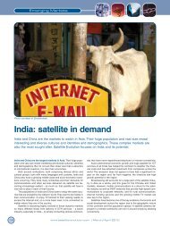
modulation can greatly improve the efficiency of utilization of frequency spectrum. For example a<br />
54 MHz Ku‐band transponder using 32APSK modulation can produce over 200 Mbps bandwidth,<br />
compared with 48 Mbps using QPSK modulation. However, with higher modulation, more power is<br />
required. This is why high modulation rates are possible only with earth stations using large<br />
amplifiers capable of delivering the required power.<br />
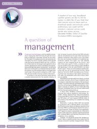
Figure 1: Required C/N versus spectrum efficiency on the AWGN channel (ideal demodulation), where C/N refers<br />
to the average power 1<br />
1 EBU TECHNICAL REVIEW – October 2004, A. Morello and V. Mignone: <strong>DVB</strong>‐<strong>S2</strong>— ready for lift off<br />
_____________________________________________________________________________________<br />
2
In reality, there are two other factors that affect modulation and power used in satellite<br />
transmission: weather conditions and EIRP of location. When the link budget is calculated, it is<br />
based on the worst case scenario, which means that under heavy rain conditions (as specified by<br />
ITU’s classification of rain fade zone), the satellite link must continue to function normally. To make<br />
sure the link is always on, the lowest possible modulation and highest possible power will be used.<br />
However, in reality, this kind of situation only takes place on very rare occasions. For example,<br />
according to Environment Canada’s statistics, heavy rain in Ottawa will take place on average only 5<br />
days a year. If the link budget is calculated based on this heavy rain situation, this will translate to a<br />
tremendous waste of energy and bandwidth for 360 days a year. On those 360 days, higher<br />
modulation and much less power could be used to generate more bandwidth.<br />
Rainfall<br />
Days<br />
>= 0.2 mm 118.5<br />
>= 5 mm 45<br />
>= 10 mm 23.9<br />
>= 25 mm 5<br />
Table 1: Annual Average Rainfall Days in Ottawa 1971‐2000 2<br />
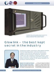
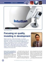
Another factor is satellite power distribution or EIRP by location,<br />
which is different from one place to another. For example, the area<br />
that is covered by the 44 dB contour should be able to use lower<br />
level modulation in order to make sure it can continuously receive<br />
good signal levels. This is based on the assumption that the rest of<br />
the conditions remain the same as those covered by the 48 dB<br />
contour, such as the size of antenna and weather. However, if lower<br />
modulation is implemented in all areas, then those in the 48 dB<br />
contour will be short changed, as they are supposed to be able take<br />
advantage of higher modulation to save frequency spectrum or<br />
power.<br />
Figure 2: Sample of <strong>Satellite</strong> Footprint<br />
The indication here is that if modulation and power levels can be adjusted accordingly, this will<br />
greatly improve the efficiency of utilization of satellite power and frequency spectrum. This was<br />
2 Source: Environment Canada Website<br />
_____________________________________________________________________________________<br />
3
not possible in the past. For example, under the <strong>DVB</strong> regime, the carrier comes from the hub, which<br />
is called the Forward link. Forward link is a large carrier with one fixed modulation and coding<br />
setup, no matter what the receiver’s EIRP and receiver’s weather conditions may be at its location.<br />
This was the case for most satellite links in the past, where modulation and coding changes were<br />
accomplished through a manual operation.<br />
Recent improvements in the <strong>DVB</strong>‐<strong>S2</strong><br />
technology have enabled this<br />
important change to be<br />
accomplished automatically and ondemand;<br />
this process is called<br />
Adaptive Coding and Modulation<br />
(<strong>ACM</strong>).<br />
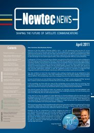
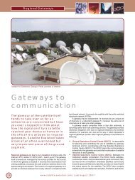
Figure 3 to the right is an illustration<br />
of how <strong>ACM</strong> enables the use of<br />
various modulations and coding<br />
combinations over different EIRP<br />
areas and weather conditions.<br />
Compared with the lower EIRP area,<br />
the high EIRP area has been<br />
implemented at higher level<br />
modulation and more powerful<br />
coding combination to achieve<br />
high throughput.<br />
Figure 3: <strong>ACM</strong> enables each remote to achieve maximum data<br />
throughput by utilizing the most efficient coding and modulation scheme<br />
dependent upon the location within the satellite contour, antenna size,<br />
and clear sky conditions versus rain fade.<br />
3 www.satellite-evolution.com | November/December 2007, Jonathan Barter, Planning for <strong>DVB</strong>-<strong>S2</strong>/<strong>ACM</strong><br />
_____________________________________________________________________________________<br />
4
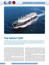
Figure 4: Capacity Comparison of <strong>DVB</strong>‐<strong>S2</strong> <strong>ACM</strong> over <strong>DVB</strong>‐<strong>S2</strong> CCM and <strong>DVB</strong>‐S<br />
/Source: www.hughes.com<br />
Such advancements made possible through the new <strong>ACM</strong> technology are very significant. They<br />
represent over 50%‐80% bandwidth improvement over the traditional <strong>DVB</strong> standard.<br />
_____________________________________________________________________________________<br />
5
C‐COM’s next generation iNetVu ® 7000 Controllers already support the latest <strong>DVB</strong>‐<strong>S2</strong>/<strong>ACM</strong><br />
modulation technique. This capability will allow C‐COM’s auto deploying antenna systems to work<br />
with the most advanced satellite modems and two‐way services which are being deployed<br />
worldwide using the <strong>DVB</strong>‐<strong>S2</strong>/<strong>ACM</strong> technology.<br />
The major benefit of supporting <strong>DVB</strong>‐<strong>S2</strong>/<strong>ACM</strong> is its international acceptance and compliance by<br />
<strong>DVB</strong>‐<strong>S2</strong>/<strong>ACM</strong> satellite remote equipment vendors. Having this feature available in the 7000<br />
controller makes the iNetVu ® Comm‐On‐The‐Pause auto deploying technology one of the fastest at<br />
acquiring satellite today. Controllers that do not have such capability but are required to work on<br />
<strong>DVB</strong>‐<strong>S2</strong>/<strong>ACM</strong> satellites not having any <strong>DVB</strong>‐S1 carriers available on them, would have to rely on<br />
modem integration, or a combination of either modem and beacon, or modem and reference<br />
satellite with <strong>DVB</strong>‐S1 carrier, in order to complete the acquisition. This is a longer process, which<br />
can usually add an additional 5 to 10 minutes to the typical <strong>DVB</strong>‐S1 based acquisition process. In<br />
addition, this can be an expensive affair if additional hardware has to be purchased to make this<br />
possible (like beacon receiver).<br />
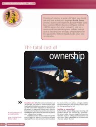
Figure 5: iNetVu ® 7000 Auto‐pointing Controller<br />
By directly zooming<br />
onto the <strong>S2</strong>/<strong>ACM</strong> carrier<br />
on the same service satellite, the iNetVu ® systems can find <strong>DVB</strong>‐<strong>S2</strong>/<strong>ACM</strong> satellites in less than 2<br />
minutes.<br />
With this new capability the iNetVu ® 7000 controller leads the way for a new generation of <strong>DVB</strong>‐<br />
<strong>S2</strong>/<strong>ACM</strong> capable controllers. Its early adaptation has positioned C‐COM far ahead of its competition<br />
and in sync with the new generation of modems and satellites supporting this latest advancement<br />
in satellite technology.<br />
_____________________________________________________________________________________<br />
6