Keyless Entry User Guide - Procare Software
Keyless Entry User Guide - Procare Software
Keyless Entry User Guide - Procare Software

You also want an ePaper? Increase the reach of your titles
YUMPU automatically turns print PDFs into web optimized ePapers that Google loves.
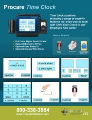
Getting Started <strong>Guide</strong><br />
• <strong>Keyless</strong> <strong>Entry</strong> System<br />
Last revised: Dec. 22, 2009<br />
<strong>Procare</strong> <strong>Software</strong><br />
3581 Excel Drive, Medford, OR 97504<br />
Fax: (541) 858-7008<br />
Web: <strong>Procare</strong><strong>Software</strong>.com<br />
Sales: 1-800-338-3884 | Mon. – Fri. 8 AM – 4 PM Pacific | Email: sales@procaresoftware.com<br />
Support: 1-800-964-1729 | Mon. – Fri. 6 AM – 4 PM Pacific | Email: tech@procaresoftware.com
Page ii<br />
This page intentionally left blank.
Dear Friend:<br />
Thank you for choosing ProCare <strong>Software</strong> as your Management System. Your confidence in us is greatly<br />
appreciated.<br />
The mission of Professional Solutions is to provide the best management software and quality services to<br />
our customers. Specifically, our commitment is centered around the following goals and objectives:<br />
• To always remember that the relationship between ourselves and our customer is one of sincere trust<br />
and to do everything possible to achieve and maintain that trust.<br />
• To deliver to each customer the absolute best management software product and quality service, now<br />
and into the future.<br />
• To remember that it is our duty and obligation to serve our customers so that their goals and objectives<br />
are fulfilled.<br />
• To always be aware that each customer must be treated with care, concern, dignity and sensitivity.<br />
• To at all times conduct ourselves in the utmost professional manner, adhering to the highest ethical<br />
standards and putting the interests of our customers first.<br />
Thank you for letting us have this opportunity to serve your needs.<br />
Jeffrey R. Blum, President<br />
Professional Solutions<br />
Page iii
<strong>Software</strong> License Agreement<br />
Professional Solutions grants you a non-exclusive, non-transferable license* to use this copy of the ProCare Management<br />
<strong>Software</strong> and accompanying documentation. This license is not a sale. Title and copyrights to the program and accompanying<br />
documentation and any copy made by you remain with Professional Solutions. Unauthorized copying of the program or the<br />
accompanying documentation, or failure to comply with the following restrictions, will result in automatic termination of this<br />
license and any software support through Professional Solutions, and will make available to Professional Solutions other<br />
legal remedies. This software license authorizes you to utilize the program according to the following terms:<br />
Acceptable<br />
1. Use of this program at one registered location.<br />
2. Installation of this program at more than one computer only if the computers are located at the center that originally<br />
purchased the site license to use the program. The original site for the software will have the site name encoded into the<br />
program.<br />
3. Making one copy of the program in machine readable format solely for backup purposes. All proprietary notices must<br />
accompany the copy.<br />
Unacceptable<br />
1. Use of this program at more than one center, without a site license for that site.<br />
2. Duplication (except for backup), modification, translation, reverse engineering, decompiling, disassembling, or creating<br />
derivative works based on the program or documentation.<br />
3. Renting, transferring, or granting any rights in the program or documentation in any form to any person without the prior<br />
written consent of Professional Solutions.<br />
4. Removing any proprietary notices, labels or warnings on the program and accompanying documentation.<br />
5. Selling or otherwise transferring your software license to a new owner or other business entity.*<br />
* Professional Solutions reserves the right to transfer the <strong>Software</strong> License with an associated fee.<br />
Page iv
<strong>Software</strong> Warranty<br />
Professional Solutions warrants that, for a period of ninety (90) days from the date of delivery to you, as evidenced by the<br />
date on your invoice, the media on which the program is furnished under normal use will be free from defects in materials<br />
and workmanship and the program under normal use will function without significant errors that make it unusable. If you<br />
notify Professional Solutions within the warranty period of any such defects, Professional Solutions will replace the defective<br />
media.<br />
The sole remedy for breach of this warranty is limited to replacement of defective materials or refund of purchase price and<br />
does not include any other kinds of damages.<br />
The entire risk as to the performance of the programs is with the purchaser. Professional Solutions does not warrant that the<br />
operation of the programs will be uninterrupted or error-free. Professional Solutions assumes no responsibility or liability of<br />
any kind of errors in the programs or documentation or for the consequences of any such errors. In no event will Professional<br />
Solutions be liable for any damages, including loss of data, lost profits, or other special, incidental, consequential or indirect<br />
damages from the use of the program or accompanying documentation, however caused and on any theory of liability. You<br />
acknowledge that the license fee reflects this allocation of risk.<br />
Hardware Warranty<br />
Professional Solutions, 3581 Excel Drive, Medford, OR 97504, warrants that this device is free from all defects in material<br />
and workmanship when used under normal conditions for a period of one (1) year from the date of original purchase.<br />
Should the product fail to perform properly, we will repair or replace it at our option subject to verification of the defect or<br />
malfunction. Professional Solutions will bear the cost of shipping the unit via UPS ground.<br />
Warranty is void if the owner repairs or modifies the product. Warranty excludes any other liability other than that expressly<br />
stated above including but not limited to any incidental or consequential damages. Warranty does not cover (i) products<br />
which have been damaged by negligence, misuse or accident or which have been modified or repaired by unauthorized<br />
persons (ii) cracked or broken cabinets of units damaged by excessive heat or continued exposure to the elements.<br />
ATTENTION:<br />
Warranty VOID if wiring is altered in any way.<br />
Page v
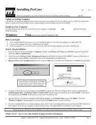
ProCare <strong>Keyless</strong> <strong>Entry</strong><br />
READ FIRST – MUST INSTALL DRIVERS!<br />
USB / Serial Adapter<br />
Why does the <strong>Keyless</strong> <strong>Entry</strong> need an Adapter<br />
USB devices are limited to a cable length of 10-15 feet. The <strong>Keyless</strong> <strong>Entry</strong> uses a serial connection so<br />
your computer can be farther away from the Relay Box. Using a USB / Serial adapter allows you to<br />
connect to a USB port on your computer. If your computer has a serial port then it is not necessary to<br />
use an adapter.<br />
Install Driver First, then Connect Adapter<br />
You MUST install the driver BEFORE you connect the adapter to your computer.<br />
For Windows 7: Download and install the latest driver from the USB Gear web site. Go to<br />
<strong>Procare</strong>Support.com and search for article # KB0250 which contains a link. Once the driver is installed<br />
continue with step 3 below.<br />
For Windows Vista, XP, 2003 or 2000: Use the mini CD (included) and follow these steps.<br />
1. Log on to your computer as a local Administrator and insert the USBGear mini CD.<br />
If the CD does not start on its own then Open “My Computer” and Dbl-click the CD drive<br />
(should say “USBGear”) then Dbl-click the file named Start (or Start.html).<br />
2. Under “Driver Installation” click Windows Vista, 2003, XP, 2000 Driver. If you have a choice<br />
between Save and Run choose Run. Installation takes just a few seconds. When it is complete<br />
you may need to tap Enter on your keyboard to close the window.<br />
3. Plug the blue colored Adapter into a USB Port on your computer. The blue adapter should have<br />
come pre-attached to a grey colored RJ-11 Adapter (Figure 2).<br />
Optional: If needed you may attach the silver colored USB extension cable to the blue<br />
adapter. Then plug the silver extension cable into your computer. (Figure 3).<br />
Figure 1<br />
USB Adapter Only<br />
Figure 2<br />
USB Adapter connected to<br />
RJ-11 Adapter<br />
Figure 3<br />
Optional silver extension<br />
cable connected to USB<br />
adapter<br />
Page vi
TM<br />
ProCare<br />
management system<br />
<strong>Keyless</strong> <strong>Entry</strong><br />
System<br />
See reverse side for Wiring Diagram and<br />
Product Specifications<br />
Installation Instructions<br />
Before you begin...<br />
Connecting the <strong>Keyless</strong> <strong>Entry</strong> System (KES) is not complicated; however, unless you are experienced in doing<br />
so, electrical connections should be made by a qualified technician. This unit is not intended for after hours<br />
security. A dead bolt or similar device will be needed when the building is closed.<br />
Each KES is shipped with the following components. Verify that your box contains:<br />
a.) Keypad with short attached cable, cable coupler, and long (8 wire) cable with RJ45 connectors.<br />
b.) Relay Box<br />
c.) Chime (Doorbell) Kit with doorbell, transformer and two (2) manual override buttons,<br />
d.) Wire with RJ11 connectors e.) RJ11 to Serial Adapter f.) Serial to USB Adapter & USBgear mini CD<br />
g.) <strong>Procare</strong> CD and Getting Started <strong>Guide</strong><br />
Please set up and test these components on a table top prior to mounting them in their final locations.<br />
Mounting the components (order is not important).<br />
1 Mount the keypad in the desired location. Be sure to allow a cable feed-through hole. The keypad<br />
should be in a location (indoors or out) that does not receive direct sun or rain. Attach the short<br />
cable on the keypad to the cable coupler then to the long RJ45 cable (supplied) or substitute<br />
your own straight through CAT-5 network cable.<br />
2 Mount the relay box in a protected indoor location, such as the attic of the building. Again, keep in<br />
mind the RJ11 cable (provided) will need to reach from the relay box to the computer.<br />
3 Mount the doorbell transformer in a protected indoor location. Make sure a standard 110V power outlet<br />
is within reach of the transformer.<br />
4 Mount the doorbell in an audible, central, location.<br />
5 Mount the door strike or magnetic lock unit per the manufacturer’s instructions.<br />
6 Mount the manual override button(s) in the desired location(s).<br />
Making the electrical connections (If you have not already done so, TURN OFF ELECTRICITY).<br />
7 Connect the long RJ45 cable coming from the keypad to the Relay Box terminal marked “Keypad.”<br />
8 Connect a 110V power supply to the doorbell transformer.<br />
9 Using 20-2 gauge wire, connect the doorbell transformer to the<br />
relay box using the terminal marked “Transformer.”<br />
10 Using 20-3 gauge wire, connect the doorbell to the relay<br />
box using the terminal marked “Doorbell.”<br />
11 Using 20-2 gauge wire, connect the door strike and manual<br />
override buttons (if desired) to the relay box using the<br />
terminal marked “Door Control Circuit”.<br />
12 See previous page for details. Install driver from the USBGear<br />
mini CD. Then connect USB-Serial adapter to computer’s USB<br />
port. (Serial-RJ11 adapter should already be attached).<br />
13 Connect RJ11 cable to relay box terminal marked<br />
“Computer Serial Port.” Attach other end of cable to RJ11<br />
9 10 11 13 7<br />
adapter at computer. See Getting Started <strong>Guide</strong> for installation of <strong>Procare</strong> CD and software use.<br />
Sales: 1-800-338-3884 www.procaresoftware.com Support: 1-800-964-1729<br />
rev 4/06/2009
Product Specifications<br />
Power required:<br />
12-16 volts DC (or AC) @ 100ma supplied by attendant 16VAC<br />
doorbell transformer. Power is applied to terminal strip on relay box.<br />
Door strike requires separate power supply (by user).<br />
Keypad/Wall frame unit: Display – 2 LEDs, “Ready” (red) and “Accept” (green)<br />
Environment – Indoor and sheltered outdoor,<br />
Dimensions – length 7.4”, width 4.1”, height 2.43” (including wall frame)<br />
Keypad case material – black ABS<br />
Wall frame material – .075” black anodized aluminum<br />
Weight – 14.7 oz.<br />
Relay Box:<br />
RS232 port:<br />
Provides interfaces to power transformer, computer, keypad, doorstrike and doorbell.<br />
Display – 1 LED “power” (red)<br />
Environment – Indoor use only.<br />
3 Relays rated at 10 amp. Actual current used: approx 0.1 amp.<br />
Dimensions – lenth 5.1” (incl mounting flanges), width 2.8”, height 1.6”<br />
Case material – black ABS<br />
Weight – 5.5 oz.<br />
RJ11 jack. Standard modular phone type cable to PC serial port, fitted with RJ11 to<br />
DB9 serial converter and serial to USB adapter.<br />
Hardware handshake is continually jumper wired to “on” within the converter.<br />
Data rate is set to 9600bps<br />
Wiring Diagram<br />
Warranty VOID if wiring is altered in any way.<br />
Relay Box<br />
Transformer Doorbell Door Control<br />
Circuit<br />
8 Wire Cable with RJ-45 connectors.<br />
Use the supplied cable or<br />
substitute your own straight through<br />
CAT-5 network cable.<br />
Manual Open. Allows staff person<br />
inside to manually ‘buzz’ the door open<br />
so people without codes may enter the<br />
building.<br />
4 Cond. Modular Cable<br />
Doorbell Transformer<br />
RJ11<br />
110 AC 12-16VAC<br />
Double adapter: RJ11 to<br />
Serial and Serial to USB<br />
Front<br />
“Front”<br />
“Trans”<br />
Trans<br />
“Rear”<br />
NC<br />
Rear<br />
C<br />
NO<br />
Strike Power<br />
Supply<br />
RJ45<br />
Typical Normally-Open<br />
Connection<br />
Cable Coupler<br />
8 Wire Cable<br />
(part of keypad)<br />
Disable Key Switch. Not supplied.<br />
Disables the keypad. Prevents the door<br />
from being opened after hours. Not<br />
necessary if a dead-bolt is used for after<br />
hours security.<br />
Door Strike. Diagram assumes an<br />
Electric Door Strike with typical Normally<br />
Open connection. For Magnetic<br />
Locks wiring must be handled appropriately.<br />
The door strike, its transformer &<br />
wire are not supplied. 14-20 ga. wire is<br />
recommended.<br />
USB or Serial Port<br />
Doorbell On/Off Switch.<br />
Optional, not supplied. Disables<br />
the announcement bell. Allows the<br />
doorbell to be turned off during<br />
periods of heavy use.<br />
2-Chime Doorbell<br />
“Rear” = Announce <strong>Entry</strong><br />
“Front” = Guest Doorbell<br />
Keypad
<strong>Procare</strong> <strong>Keyless</strong> <strong>Entry</strong> System<br />
The <strong>Keyless</strong> <strong>Entry</strong> software is designed to run on the Windows® family of operating systems including:<br />
Windows Vista, XP and 2000.<br />
Installing the <strong>Software</strong><br />
1. Log on to your computer with local “Administrator” privileges.<br />
2. Close all programs, then insert the <strong>Procare</strong> CD.<br />
3. Browse to the <strong>Keyless</strong><strong>Entry</strong> folder on the CD and run KES.exe then follow the on screen prompts.<br />
• Windows Vista: Click Start > Computer > <strong>Procare</strong> CD > open the <strong>Keyless</strong><strong>Entry</strong> folder > right-click the file<br />
named KES (it may say KES.exe) and choose “Run as Administrator”.<br />
• Windows XP or 2000: Click Start > My Computer > <strong>Procare</strong> CD > open the <strong>Keyless</strong><strong>Entry</strong> folder > doubleclick<br />
the file named KES (it may say KES.exe).<br />
4. At the end of the installation click FINISH. You may be asked to restart your computer. When the installation is<br />
complete a <strong>Keyless</strong> <strong>Entry</strong> System shortcut will appear on your desktop.<br />
Using the <strong>Keyless</strong> <strong>Entry</strong> software<br />
Double click the <strong>Keyless</strong> <strong>Entry</strong> System shortcut (on your desktop) to start the<br />
program. The program allows users to edit codes and transmit them to the keypad<br />
device as well as monitor codes entered at the keypad. The device does not store<br />
codes entered at the keypad therefore the program must be running in order to use<br />
the monitoring function. When minimized the KES icon will appear in the system<br />
tray (lower right corner of your computer near the time display). To display the<br />
KES program again double click the tray icon or right click and select Show.<br />
Monitor Codes<br />
The first screen displayed is Monitor Codes. This screen<br />
records all activity at the keypad. If a correct code is<br />
entered it will display the time, the code entered and the<br />
user’s name. If an incorrect code is entered it will display<br />
the time, the code entered and an invalid code message.<br />
Use the Start and Stop button to begin or end monitoring<br />
(the button toggles between Start and Stop when clicked).<br />
The Clear button will erase all of the entries displayed.<br />
The Notepad button will cut and paste the entries<br />
displayed to a Notepad file. If the Transmit or Options<br />
buttons are pressed, the monitoring will stop. Monitoring<br />
automatically resumes when you return from those screens.<br />
Entries are displayed each time the monitoring is stopped<br />
and started.<br />
NOTE: The list displayed on the monitoring screen is not<br />
saved when you exit. In order to save the entries, click the<br />
Notepad button and save the file from within Notepad.<br />
NOTE: Monitoring only occurs while the KES application<br />
is open and running. The KES device itself does not store<br />
or monitor any activity at the keypad.<br />
<strong>Keyless</strong> <strong>Entry</strong> System Page 1
<strong>Procare</strong> Import for version 9.1<br />
The <strong>Procare</strong> Import screen allows you to import user codes<br />
from the Family Data and Employee Data modules of<br />
<strong>Procare</strong> version 9.1 only. Start by selecting the correct<br />
<strong>Procare</strong> data directory for the modules. To determine which<br />
codes are imported select the corresponding checkbox for<br />
each module. You then have the option of using either the<br />
Attendance ID codes or selecting from a dropdown list of<br />
user defined fields from each module.<br />
NOTE: Click the Transmit button to import and send<br />
codes to the keypad.<br />
Additional Codes for <strong>Procare</strong> v10 or 9.1<br />
For <strong>Procare</strong> v10 ALL CODES must be entered under the<br />
"Additional Codes" tab or you may choose to enter a single<br />
code used by everyone, then periodically (perhaps once each<br />
month) change the code.<br />
The Additional Codes screen allows you to add, edit and<br />
delete codes in addition to any codes imported from <strong>Procare</strong><br />
9.1. The first and last name fields are displayed on the<br />
monitoring screen when the code is entered. The Select<br />
button randomly generates codes. Highlighting a row and<br />
clicking the Restrict button will remove the codes from use<br />
and not allow them to be transmitted to the keypad. When<br />
doing this, you must enter a reason why they are being<br />
restricted. See the Restricted Codes screen to view the<br />
removed codes. Highlighting a row and selecting the Trash<br />
button will delete the row. Any changes to these codes will<br />
not take effect until they are transmitted to the keypad.<br />
NOTE: Any codes added here are for use with the keypad<br />
only. These codes do not transfer back to <strong>Procare</strong>. Any<br />
codes imported from <strong>Procare</strong> version 9.1 cannot be modified<br />
in the KES application.<br />
Restricted Codes<br />
The Restricted Codes screen displays codes that cannot be<br />
used by the KES device. You may manually enter codes<br />
here or have them transferred over from the Additional<br />
codes screen. When a Transmit is executed, the list of<br />
codes is compared to the Restricted Codes list. Any<br />
matches are displayed and the transmission is stopped.<br />
Codes that are imported from <strong>Procare</strong> 9.1 are also checked<br />
against this list.<br />
NOTE: Codes entered on the KES restricted list do not<br />
affect the codes in <strong>Procare</strong> itself.<br />
Page 2<br />
<strong>Keyless</strong> <strong>Entry</strong> System
Transmit<br />
The Transmit screen is used to upload code list and settings<br />
to the KES device. All codes listed in the Additional Codes<br />
screen, as well as any imported from the <strong>Procare</strong> modules,<br />
are sent to the KES device. The Inquire button will<br />
retrieve information from the KES device such as the<br />
number of codes currently stored in the device. The Start<br />
button executes the transmission. If any of the codes being<br />
transmitted are on the Restricted List, they will be<br />
displayed and the transmission will be stopped. You must<br />
resolve the conflict by removing the code from the<br />
Restricted List, changing the code in the Additional Codes<br />
list, or changing it in <strong>Procare</strong> 9.1 as appropriate. Once the<br />
transmission is completed a list of codes is displayed on<br />
screen. You may use the Notepad button to create a text<br />
file with this information.<br />
NOTE: Monitoring will stop once the Transmit screen is<br />
displayed. Monitoring will continue automatically upon<br />
exiting.<br />
Options<br />
The Options screen allows you to change certain settings<br />
in the KES device.<br />
Select Serial Port allows you to change which COM Port<br />
the KES device is connected to. The drop down list will<br />
display a list of available COM Ports.<br />
Code <strong>Entry</strong> Delay is the amount of time you have<br />
between entering each digit, before the KES device resets<br />
itself.<br />
Door Bell Control allows you to turn the doorbell on or<br />
off, turn the announcement doorbell on or off, select a<br />
delay duration and set the number of wrong codes entered<br />
consecutively before the doorbell goes off.<br />
Select Number of Digits in <strong>Entry</strong> Code allows you to set<br />
the length of the codes to be entered.<br />
Electric Door Control allows you to set the delay between<br />
when a correct code is entered and when the door unlocks<br />
and the duration the door remains unlocked.<br />
Any changes to the options will not take effect until they<br />
are transmitted to the KES device.<br />
NOTE: Monitoring will stop once the Options screen is<br />
displayed. Monitoring will continue automatically upon exiting.<br />
<strong>Keyless</strong> <strong>Entry</strong> System Page 3
This page intentionally left blank.<br />
Page 4<br />
<strong>Keyless</strong> <strong>Entry</strong> System