Domestic Loop System (DLS) - Hearing Loop
Domestic Loop System (DLS) - Hearing Loop
Domestic Loop System (DLS) - Hearing Loop

You also want an ePaper? Increase the reach of your titles
YUMPU automatically turns print PDFs into web optimized ePapers that Google loves.
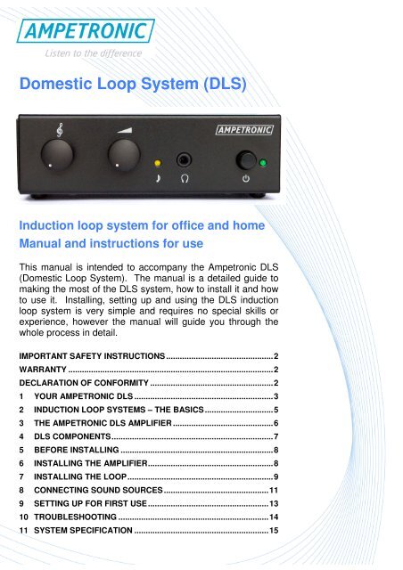
<strong>Domestic</strong> <strong>Loop</strong> <strong>System</strong> (DLS)<br />
Induction loop system for office and home<br />
Manual and instructions for use<br />
This manual is intended to accompany the Ampetronic DLS<br />
(<strong>Domestic</strong> <strong>Loop</strong> <strong>System</strong>). The manual is a detailed guide to<br />
making the most of the DLS system, how to install it and how<br />
to use it. Installing, setting up and using the DLS induction<br />
loop system is very simple and requires no special skills or<br />
experience, however the manual will guide you through the<br />
whole process in detail.<br />
IMPORTANT SAFETY INSTRUCTIONS ...............................................2<br />
WARRANTY ..........................................................................................2<br />
DECLARATION OF CONFORMITY ......................................................2<br />
1 YOUR AMPETRONIC DLS .............................................................3<br />
2 INDUCTION LOOP SYSTEMS – THE BASICS..............................5<br />
3 THE AMPETRONIC DLS AMPLIFIER ............................................6<br />
4 DLS COMPONENTS.......................................................................7<br />
5 BEFORE INSTALLING ...................................................................8<br />
6 INSTALLING THE AMPLIFIER.......................................................8<br />
7 INSTALLING THE LOOP................................................................9<br />
8 CONNECTING SOUND SOURCES ..............................................11<br />
9 SETTING UP FOR FIRST USE.....................................................13<br />
10 TROUBLESHOOTING ..................................................................14<br />
11 SYSTEM SPECIFICATION ...........................................................15<br />
1
IMPORTANT SAFETY INSTRUCTIONS<br />
1. Read these instructions.<br />
2. Keep these instructions for future reference.<br />
3. Heed all warnings.<br />
4. It is important to follow all instructions.<br />
5. Do not use this equipment near to water.<br />
6. Clean only with a dry cloth.<br />
7. Do not place objects filled with water such as a vase near or on the<br />
equipment.<br />
8. Do not install the DLS amplifier near to sources of heat such as radiators,<br />
stoves or other equipment producing heat.<br />
9. Do not place the DLS amplifier in a fully enclosed space; ensure that the<br />
amplifier has ventilation when in use.<br />
10. This equipment is designed only for servicing by qualified personnel.<br />
Servicing is required when the apparatus has been damaged or exposed to<br />
rain or moisture, or has been dropped.<br />
WARRANTY<br />
This product carries a two year parts and labour guarantee which may be<br />
invalidated if instructions are not followed correctly or if the unit is misused or used<br />
for an unintended purpose.<br />
Refer all enquiries relating to the product guarantees to your reseller or distributor.<br />
DECLARATION OF CONFORMITY<br />
Manufacturer:<br />
Declares that:<br />
Ampetronic Ltd.<br />
Northern Road, Newark, NG24 2ET. United Kingdom.<br />
Ampetronic <strong>Domestic</strong> <strong>Loop</strong> Amplifier, type name ‘DLS’<br />
Conforms to the following directives and norms:<br />
Directive 2004/108/EC<br />
EMC: EN61000-6-3:2007 Emission<br />
EN61000-6-1:2007 Immunity<br />
Directive 2006/95/EC<br />
Safety: EN60065: 2002<br />
22 nd November 2007<br />
Leon Pieters, Technical Director<br />
Ampetronic Ltd.<br />
2
1 YOUR AMPETRONIC DLS<br />
Your Ampetronic DLS will deliver excellent sound quality directly to hearing aids or<br />
special receivers, allowing users to hear direct high quality sound from any source, for<br />
example televisions, telephones, computers and doorbells. If you or people you know<br />
have a hearing impairment, the Ampetronic DLS can be very valuable and can<br />
dramatically improve quality of life within your own home or office.<br />
How will the Ampetronic DLS help you<br />
BE INDEPENDANT<br />
You will be in complete control of the volume that you hear without<br />
affecting others – no more arguments over the TV volume!<br />
BE IN CONTROL<br />
You can combine sounds from many sources, for example television,<br />
computer, telephone and a microphone so they are all at the ideal<br />
volume with no adjustment of hearing aids or sound sources.<br />
HEAR CLEARLY<br />
You can turn off all interfering background noise and hear only the<br />
sounds that you want to hear, improving concentration and reducing<br />
tiredness, and making listening to any sounds much more enjoyable.<br />
BE SAFE<br />
You can make sure that any alert or warning such as a fire alarm or<br />
doorbells can override whatever you are listening to, ensuring you<br />
never miss a phone call, a visitor, or an emergency.<br />
Key features of the Ampetronic DLS<br />
Excellent sound quality World leading<br />
technology used in professional audio<br />
systems around the world - no<br />
compromise in sound quality.<br />
Multiple inputs Up to 4 different sound<br />
sources can be used simultaneously<br />
Automatic volume control Volume<br />
automatically adjusts, however loud or<br />
quiet the TV programme or phone call –<br />
you do not need to adjust anything.<br />
Design and safety standards<br />
Designed to the highest safety<br />
standards for your piece of mind.<br />
Automatic priority switching for<br />
‘alerts’ An alert input sound will stay off<br />
until an alarm rings or similar sound is<br />
heard, then it will override any other<br />
sound to ensure that you hear the<br />
warning sounds.<br />
Discrete Designed to be elegant and<br />
discrete for either home or office<br />
environments<br />
Simple installation Suitable for<br />
installation by anyone – no experience or<br />
knowledge required.<br />
3
1.1 How and where can you use the DLS<br />
The Ampetronic DLS is suitable for use in the home or office, wherever you might need<br />
to hear entertainment, communications or alarms. The amplifier can be installed in<br />
any indoor environment and used wherever you want to be.<br />
The Ampetronic DLS transmits sound directly to a hearing aid or receiver as safe and<br />
invisible magnetic waves. The sound can be received when the user is within a loop,<br />
which can be very small – as small as a single chair or sofa – or which can be around<br />
a room or area up to 5 x 6m or 30m 2 (a larger room or area can be used if a lower<br />
signal strength is acceptable which will depend greatly on your hearing aids or<br />
receiver).<br />
The amplifier can take up to 4 different sound sources simultaneously, from a very<br />
wide range of possible sources, allowing you to fit the DLS system to match your<br />
lifestyle…<br />
1.2 Induction loop systems in public places<br />
Your DLS amplifier is only one form of induction loop system – you can benefit from<br />
this technology outside of your home or office too! You may want to know where you<br />
can get this benefit in public. Typically where an induction loop system is installed for<br />
your use you will see a sign like this…<br />
Where you see the sign you should be able to switch your<br />
hearing aids to the ‘T’ setting (unless they switch automatically)<br />
or use an induction loop receiver. Where you don’t see the<br />
sign, don’t forget to ask why there is no induction loop!<br />
The variation in use of induction loop systems is significant<br />
from country to country so you will get the best information on<br />
where and how they are used by contacting the hard-of-hearing organisation in your<br />
country, by asking your hearing specialist or through an Ampetronic sales agent in<br />
your country.<br />
4
2 INDUCTION LOOP SYSTEMS – THE BASICS<br />
The Ampetronic DLS is an Induction <strong>Loop</strong> <strong>System</strong>. Induction loops are an excellent<br />
way to help anyone with a hearing impairment hear an audio communication or<br />
broadcast, both in public and in the home or office. Induction loop systems are often<br />
used in public environments from ticket counters and intercoms through to theatres<br />
and cinemas. In many countries induction loops are already the standard solution for<br />
helping the hard-of-hearing to gain fair access, and can be found installed in most<br />
public environments in the UK and parts of Scandinavia.<br />
An induction loop system consists of four parts:<br />
Sound<br />
sources<br />
1 2 Amplifier<br />
3 Wire loop<br />
4<br />
<strong>Hearing</strong> aids /<br />
receiver<br />
1. One or more sound sources – the sounds that you want to listen to directly,<br />
for example your television, hi-fi system, computer, telephone, a microphone,<br />
or alerts such as a doorbell or fire alarm<br />
2. An induction loop amplifier – a special amplifier that is connected to the<br />
various sound sources and amplifies the sound as an electrical signal into a<br />
loop<br />
3. A wire loop – a loop connected to the induction loop amplifier which goes<br />
around the area in which you would like to use the system, for example around<br />
the outside edge of your room, or around a small area such as a chair or sofa.<br />
The loop transmits the sound as a completely safe and invisible magnetic field<br />
in the area above the loop.<br />
4. Receivers, usually hearing aids – a small coil picks up the sounds broadcast<br />
through the loop. Coils – sometimes known as ‘T-coils’ or ‘telecoils’ – are<br />
often found within hearing aids, either with a small switch marked ‘T’ or<br />
automatically switching.<br />
Once an induction loop system has been installed and set-up it should require no<br />
attention, adjustment or maintenance. At any time a user can switch their hearing aids<br />
or use their receivers to hear the sounds being broadcast into the loop system.<br />
5
3 THE AMPETRONIC DLS AMPLIFIER<br />
1 2 3 4 5 6 7 8 9 10 11 12 13 14 14 15<br />
FEATURE<br />
DESCRIPTION<br />
1. TONE CONTROL Tone control, normal response with knob at centre and marker<br />
pointing up. Adjust to give your preferred sound.<br />
2. VOLUME CONTROL To adjust volume transmitted by the loop.<br />
3. SIGNAL INDICATOR When lit, the input level is high enough to ensure that the loop<br />
will be loud enough. Normally on when sound is present.<br />
4. HEADPHONE SOCKET Monitors the signal that is actually broadcast into the loop.<br />
Useful for setting up the loop and fault finding.<br />
5. POWER SWITCH To turn power on and off. The Ampetronic DLS can be left on at<br />
all times, or turned off when not used as preferred.<br />
6. POWER INDICATOR Green light, on when the unit has power and is turned on.<br />
7. RUBBER FEET To isolate the unit from vibration and heat and provide a secure<br />
and stable base in any installation.<br />
8. LOOP CONNECTOR Speaker style connector for the two cable ends of the loop.<br />
9. POWER CONNECTOR Power connector for the 12V DC power supply provided.<br />
10. INPUT 1 Audio input with twin RCA connectors (see section !8)<br />
11. INPUT 2 Audio input with twin RCA connectors (see section !8)<br />
12. INPUT 3 (ALERT)<br />
SWITCH<br />
13. INPUT 3 (ALERT)<br />
LEVEL ADJUSTER<br />
Selects line level (right) or microphone (left) for input 3<br />
Adjusts sensitivity of input 3, setting the level at which a noise<br />
will trigger the alert (priority) input<br />
13. INPUT 3 (ALERT) Alert input – sounds at this input will override other inputs, and<br />
be turned off when not in use<br />
14. INPUT 4 LEVEL<br />
ADJUSTER<br />
15. INPUT 4<br />
(MICROPHONE)<br />
Adjusts sensitivity of microphone input 4 as required<br />
Microphone input for electret style microphone (provided) with<br />
minijack input<br />
6
4 DLS COMPONENTS<br />
(1)<br />
The DLS kit contents:<br />
• DLS amplifier and instructions (1)<br />
• 30m loop cable and cable clips (2)<br />
• 1 x Clip microphone and cable (3)<br />
• 1 x Mini-jack cable (4)<br />
• 1 x RCA cables (5)<br />
• 1 x power supply (6)<br />
(2)<br />
(3) (4)<br />
(5) (6)<br />
Additional accessories<br />
Available through your local dealer.<br />
• Chair pad (7)<br />
A 40cm square pad to place<br />
under or in a cushion on a chair<br />
or sofa, to create a local field for<br />
one person, often instead of<br />
using the room loop cable.<br />
• Telephone adaptor (8)<br />
To connect a phone line or<br />
phone network to the DLS unit<br />
• SCART adaptor (9)<br />
To connect a television to the<br />
amplifier using a ‘through-<br />
SCART’ connection that does<br />
not affect your existing SCART<br />
connections.<br />
• Additional cables and<br />
microphones<br />
(7)<br />
(8) (9)<br />
Phone adaptor<br />
provided separately<br />
7
5 BEFORE INSTALLING<br />
Before the DLS system is installed<br />
please check that your environment is<br />
suitable and that you have appropriate<br />
receivers or hearing aids as follows.<br />
What receivers or hearing aids will<br />
you use<br />
To hear the output from the<br />
Ampetronic DLS you must use a<br />
receiver. For most people this will be<br />
hearing aids, which typically contain a<br />
telecoil or ‘T’ function. <strong>Hearing</strong> aids<br />
must be switched to the ‘T’ setting –<br />
some hearing aids automatically<br />
switch to the ‘T’ setting, others have a<br />
manual switch. Check with your<br />
hearing advisors or hearing aid<br />
suppliers if you are unsure of how to<br />
use your hearing aids with an<br />
induction loop system.<br />
Without hearing aids the user needs to<br />
use a receiver and headphones to<br />
hear the output from the Ampetronic<br />
DLS. The supplier of your Ampetronic<br />
DLS can help you to find a suitable<br />
receiver.<br />
Other loop systems<br />
The DLS loop system will create a<br />
strong signal that you can hear within<br />
the area of the loop. There is also a<br />
much weaker signal that carries up to<br />
10m away from a room loop. This can<br />
occasionally cause a problem if:<br />
- there is another ‘room loop’<br />
induction loop system in use within<br />
10m of your room – you may pick<br />
up interference from this loop<br />
system which you can hear in your<br />
room, or you might create<br />
interference in someone else’s<br />
loop.<br />
- you use the system for confidential<br />
or private conversations with<br />
8<br />
microphones or the telephone that<br />
you do not want others to be able to<br />
hear.<br />
Both of these problems can be avoided<br />
by using a chair pad accessory instead<br />
of a room loop.<br />
Background noise<br />
Occasionally poor quality electrical<br />
systems can create interference that<br />
you will hear if you try to use an<br />
induction loop system. Before installing<br />
the DLS, turn on your receiver or turn<br />
your hearing aids to the ‘T’ setting – if<br />
you hear a lot of background noise or<br />
hum then your room may not be<br />
appropriate for an induction loop<br />
system. Ask you supplier for advice if<br />
this happens.<br />
6 INSTALLING THE<br />
AMPLIFIER<br />
Where will you put the DLS<br />
amplifier<br />
The DLS amplifier should be placed<br />
somewhere where:<br />
• cables for each sound source can<br />
reach the amplifier<br />
• cable for the loop (chair or room loop)<br />
can reach the amplifier<br />
• volume and tone controls can be<br />
adjusted by the user<br />
The DLS amplifier can stand<br />
horizontally or be mounted on a panel<br />
(for example underneath a desk) or on<br />
a wall as shown on the next page.<br />
Installing the amplifier<br />
Find a suitable location for the amplifier<br />
at which there is access to power, to<br />
cables from the sound sources and for<br />
the loop cable.
The amplifier can either be<br />
freestanding or wall / panel mounted –<br />
see below for wall / panel mounting<br />
instructions.<br />
The location for the DLS amplifier<br />
must be indoors and dry. The DLS<br />
amplifier must not be covered by<br />
material of any kind, and must have<br />
some air movement around the case<br />
to prevent heat build up.<br />
Place the amplifier in its required<br />
location but do not connect the power<br />
lead until installation is complete.<br />
Wall / panel mounting<br />
Included in the DLS amplifier box is a<br />
template for marking out the two screw<br />
holes.<br />
Decide on the location for the DLS<br />
amplifier and use the template to mark<br />
out two screw holes. Put two screws<br />
in place (screw heads should be 6-<br />
8mm diameter). Leave the screw<br />
heads protruding by 8-10mm from the<br />
wall. Hang the DLS amplifier on the<br />
screw heads using the holes on the<br />
bottom of the case.<br />
7 INSTALLING THE LOOP<br />
Room loop installation<br />
For moving, standing up or in different<br />
locations within a room.<br />
A room loop is a loop of wire usually<br />
placed around the wall or skirting board<br />
around the edge of the room.<br />
A wire can also be used around a<br />
smaller area underneath carpet or a<br />
rug. The loop must cover the whole<br />
area in which the user needs to hear<br />
the sound from the DLS induction loop.<br />
A room loop is simple to install but does<br />
require you to be able to run a cable<br />
around your room and fix it safely using<br />
the cable clips provided, or another<br />
fixing method.<br />
• Decide what the area is that needs<br />
to be covered by the cable.<br />
• Start with one end of the cable at<br />
the DLS amplifier.<br />
• Run the cable from the cable reel<br />
provided around the edge of the<br />
area that is required to be used.<br />
Typically this will be the edge of a<br />
room.<br />
• Use cable clips (provided) to<br />
secure the loop cable, or place the<br />
loop cable underneath a rug or<br />
carpet.<br />
9
• The cable should ideally be fitted<br />
at floor or ceiling level, never at<br />
head height. The diagram shows<br />
both options as a green and a red<br />
loop.<br />
• Cable can run over doorways to<br />
prevent trip hazards, see the red<br />
loop in the diagram.<br />
• Run the free end of the cable<br />
back to the DLS amplifier.<br />
• Connect the cable ends to the<br />
amplifier – see the end of this<br />
section.<br />
• The room loop is now installed.<br />
Dealing with excess cable<br />
If there is a large amount of excess<br />
cable (more than half of the reel) then<br />
it needs to be wound carefully or<br />
removed. Please note that the<br />
minimum cable length for the system<br />
is 8m.<br />
The excess wire can be cut<br />
away with scissors or wire<br />
cutters. The end of the cable<br />
needs to have the plastic<br />
sheath removed to expose the metal<br />
ends as shown:<br />
If you can not or do not want to<br />
remove the excess wire, coil the<br />
remaining wire as follows:<br />
• Both ends should be connected to<br />
the amplifier as instructed above.<br />
• Identify the point of the free cable<br />
that is the end of the useful loop –<br />
fix or hold this temporarily to the<br />
amplifier.<br />
• Pull out the remaining cable into a<br />
loop and pull it away from the<br />
amplifier so it forms two parallel<br />
10<br />
cables with a sharp bend in the<br />
end.<br />
• Coil the two parallel cables<br />
together, tie, tape or otherwise fix<br />
the coil in place.<br />
Chair loop installation<br />
The Chair<br />
<strong>Loop</strong> pad is<br />
an optional<br />
accessory.<br />
The pad<br />
comes with<br />
5m of cable<br />
attached to<br />
allow you to<br />
sit anywhere<br />
within the<br />
room, and a<br />
connector for<br />
easy removal<br />
or connection.<br />
Make sure<br />
that the pad<br />
can be placed<br />
under or<br />
behind the chair that needs to be used<br />
and the cable can be run safely from<br />
the chair to the DLS amplifier.<br />
• Place the pad in one of three<br />
places: under the seat cushion;<br />
behind the seat back; or inside a<br />
seat cushion (seat or backrest)<br />
• Run the connecting cables to the<br />
DLS amplifier.<br />
• Cover the cable with a rug or other<br />
protection to prevent tripping or<br />
catching the cable.<br />
• Connect both ends of the loop<br />
cable to the DLS amplifier, see the<br />
end of this section<br />
• The chair loop is now installed.
Connecting the loop to the amplifier<br />
Once the loop has been installed the<br />
two cable ends must be connected to<br />
the loop connector on the DLS<br />
amplifier (shown below).<br />
First, terminate the cable ends if<br />
required so both cable ends have 5-<br />
15mm of exposed cable:<br />
The connector has<br />
two holes above a<br />
red and a black<br />
switch. When the<br />
switches are<br />
pushed down the<br />
hole is open, when<br />
the switched is<br />
pushed up the<br />
hole is closed and the loop cable will<br />
be clamped in place.<br />
Connect one end of the cable to the<br />
black terminal of the DLS amplifier:<br />
• Push the black terminal of the<br />
loop connector down<br />
• Put the cable end into the hole<br />
above the black switch<br />
• Lift up the black switch to capture<br />
the cable in place<br />
Connect the free end of the cable to<br />
the red terminal of the DLS amplifier in<br />
the same way.<br />
Check that both loop wires are<br />
securely held by the connector on the<br />
DLS amplifier<br />
8 CONNECTING SOUND<br />
SOURCES<br />
The Ampetronic DLS can accept up to<br />
4 different inputs simultaneously. What<br />
do you want to hear<br />
The possible sound sources are as<br />
follows for each of the 4 inputs on the<br />
DLS amplifier – work out what you want<br />
to connect before starting the<br />
installation.<br />
Inputs 1 and 2 (line inputs)<br />
Up to two of the following items can be<br />
connected:<br />
- Television<br />
- HiFi<br />
- Radio<br />
- Computer audio<br />
- iPOD / MP3 player<br />
- Telephone via adaptor (not<br />
provided)<br />
• Select the appropriate cable for your<br />
equipment, minijack, RCA or<br />
SCART (optional accessory).<br />
• Connect the two RCA jacks to the<br />
connectors of input 1 or input 2 and<br />
the other end to your equipment.<br />
Input 3 (alert input)<br />
This input can take any input, but is<br />
reserved for warning sounds, sounds<br />
that will not normally be heard, but<br />
when they occur it is important that they<br />
are heard.<br />
Typically connected to one of:<br />
- Microphone directed at an alert<br />
sound (e.g. telephone, fire alarm)<br />
- Alert system (e.g. Bellman Visit<br />
Pager systems)<br />
11
• Locate the switch on input 3 on<br />
the rear of the DLS amplifier and<br />
make sure that it is moved to the<br />
left for a microphone, to the right<br />
for a line input.<br />
• If using a microphone, place it as<br />
close as possible to the source of<br />
the alert or warning sound, and<br />
connect the microphone jack to<br />
input 3 of the DLS amplifier.<br />
• If using a line input, set up the<br />
sound source according to<br />
manufacturer’s instructions, and<br />
connect using a minijack cable to<br />
input 3 of the DLS amplifier.<br />
• Check that the alert input sounds<br />
when other inputs are also being<br />
used. Adjust the input level if<br />
required using the rear mounted<br />
level control. Make sure the input<br />
comes on when (and only when)<br />
an alert sound occurs.<br />
Input 4 (microphone input)<br />
This input will accept one microphone<br />
input. This might be used for:<br />
- Room sounds, e.g. speech<br />
- Television or other loudspeaker<br />
• Mount the microphone so that it<br />
can pick up the sounds that you<br />
want to hear.<br />
• Use the adhesive pad to attach to<br />
loudspeakers or any surface:<br />
• Connect the microphone jack to<br />
input 4 of the DLS amplifier.<br />
12
9 SETTING UP FOR FIRST<br />
USE<br />
Plug the unit into power using the<br />
power cord, and turn the unit on at the<br />
front panel switch. The green light<br />
should come on when there is power.<br />
• SET UP INPUTS 1 & 2<br />
If you are using either of inputs 1 or 2,<br />
turn on one of the connected sound<br />
sources and make sure that it is<br />
producing sound. If there are<br />
adjustments on the sound source (e.g.<br />
on a PC) turn the output levels to<br />
maximum.<br />
The yellow light should come on<br />
permanently or intermittently. If not<br />
then the input is too quiet. Change the<br />
programme material or turn up the<br />
input level until the yellow light is<br />
comes on.<br />
control on the rear of the amplifier next<br />
to input 3.<br />
• SET UP INPUT 4<br />
With a line input (1 or 2) connected and<br />
running with a continuous sound, test<br />
the level of the microphone input (input<br />
4) if used. Adjust the microphone level<br />
on the back panel if required so the<br />
microphone volume is balanced with<br />
the other sound sources.<br />
• ADJUSTMENTS IN NORMAL<br />
DAY TO DAY USE<br />
The amplifier should now be set<br />
correctly. Gain is automatically<br />
controlled so you should hear the right<br />
volume level whatever you are listening<br />
to, so you should not need to make any<br />
adjustments at all.<br />
• LISTEN AND SET VOLUME &<br />
TONE<br />
Set up your receivers or hearing aids<br />
to receive the loop signal, switching<br />
hearing aids to the ‘T’ setting.<br />
Sit in the position / positions that you<br />
will use the system in. Set the volume<br />
and tone on the amplifier to give you<br />
comfortable and clear sound.<br />
• SET UP ALERT INPUT 3 IF<br />
REQUIRED<br />
With input (1 or 2) connected and<br />
running with a continuous sound, test<br />
the level of the alert input (input 3) if<br />
used. In the unlikely event that the<br />
alert input does not cut in over the<br />
other sounds when a noise is<br />
produced, increase the level of this<br />
input sound, by moving the<br />
microphone closer to the sound<br />
source, or by adjusting the level<br />
13
10 TROUBLESHOOTING<br />
The Ampetronic DLS should not<br />
require any maintenance or support.<br />
In the event that you have problems,<br />
please consult list of possible<br />
problems below before contacting your<br />
supplier.<br />
1. No sound / low volume<br />
• Check that the power light (green)<br />
is on to confirm that the unit has<br />
power.<br />
• Check that there is a sound being<br />
produced by the input source<br />
• With input source making a<br />
sound, the front panel yellow light<br />
should come on permanently or<br />
intermittently. If not your input<br />
level is too low.<br />
• Check that there is a signal in the<br />
loop using headphones in the<br />
headphone jack on the front panel<br />
– if not then there is a problem<br />
with the loop or no input signal.<br />
• Check loop connections – are<br />
both loop ends connected firmly<br />
and are the cable ends properly<br />
terminated with exposed wire in<br />
the contacts<br />
2. Interference / hum / background<br />
noise in the loop<br />
• Check hearing aids / receivers set<br />
correctly<br />
• Turn the loop system off and<br />
check to see if background noise<br />
remains. If it does then the noise<br />
may be created by other electrical<br />
systems. Try turning off nearby<br />
appliances to find the source of<br />
interference. Noise may also<br />
come from another nearby loop<br />
system – are there any other loop<br />
systems within 10m of your<br />
system<br />
• If a microphone is connected to<br />
input 4, turn the level control down<br />
or disconnect the microphone –<br />
does the background noise<br />
remain If not, reduce the noise<br />
being picked up by the<br />
microphone or reduce the gain<br />
control on input 4.<br />
3. Alert input not working<br />
• Make sure that volume of alert<br />
signal is high – move microphone<br />
as close as possible to the alert<br />
sound source.<br />
• Increase output level as far as<br />
possible from any third party<br />
alerting device.<br />
14
11 SYSTEM SPECIFICATION<br />
Controls and features:<br />
Inputs:<br />
1 & 2. Four input Line level phono connector, fixed gain,<br />
allowing two stereo inputs.<br />
3. One independent mic/line input; Priority<br />
Microphone/Line control which is switchable between Mic or<br />
Line level. VOX switching is permanently enabled on this<br />
channel.<br />
4. One independent Mic input, gain control – rear panel,<br />
allowing adjustment to the correct level.<br />
DC Power input, 2.1mm, centre positive.<br />
Controls:<br />
Tone control: Independent front panel control allowing<br />
frequency response adjustment for differing installation<br />
variations.<br />
<strong>Loop</strong> volume: Independent front panel control allowing<br />
<strong>Loop</strong> output current (volume) adjustment.<br />
Microphone input 4 gain control – rear panel.<br />
Input specifications:<br />
Microphone input 4:<br />
Connector: 3.5mm mono jack socket.<br />
One independent microphone input suitable for use with an<br />
unbalanced electret microphone.<br />
Input impedance: 8k!.<br />
Phantom voltage: 6V via 10k! source.<br />
Input sensitivity: -60dBu for maximum output<br />
Switchable Line / Mic input 3:<br />
Line input selected:<br />
Connector: 3.5mm mono jack socket.<br />
Slide switch selection.<br />
Input impedance: 820k!.<br />
Input sensitivity: Line input selected: -20dBu for maximum<br />
output after VOX enabled at -12dBu<br />
Microphone input selected:<br />
Levels as per microphone input 4.<br />
Line level inputs 1 and 2:<br />
4-way phono input connector. Fixed gain.<br />
Input sensitivity: -10dBu for maximum output.<br />
Overload: >30dBu<br />
Compression:<br />
Compression Dynamic range: >36dB before overload.<br />
(Typically 40dB).<br />
Compression indication via amber signal LED.<br />
Efficiency: ± 1 dB across 40dB dynamic range.<br />
Attack and decay times optimised for speech.<br />
Attack time: Less than 5ms; Decay time: Less than 2 seconds.<br />
Frequency response:<br />
80 Hz to 6.3 kHz ± 1.5dB into 1! load at low level, measured<br />
as loop current with no Metal Loss correction.<br />
15<br />
Tone control:<br />
A modified tone control allowing a flat response or bass boost<br />
/ HF cut or HF boost / bass cut, with additional HF boost to<br />
allow compensation for distortion due to metal structures in<br />
surrounding buildings.<br />
Outputs:<br />
Headphone monitoring output via front panel with stereo<br />
3.5mm jack.<br />
Output connection: <strong>Loop</strong>, finger operated quick connect<br />
output connector.<br />
Current: >2.4A RMS into 1!.<br />
Voltage: >3.2V RMS.<br />
<strong>Loop</strong> resistance: 0.3! to 1.0! resistive or 1.5! maximum<br />
reactive impedance at 1.6 kHz.<br />
Connection: Finger operated speaker type connector.<br />
Area coverage:<br />
>30m 2 coverage to requirements of IEC60118-4, or use with<br />
supplied special loop pad.<br />
Note that the amplifier can drive loops far in excess of this<br />
size if the full performance of IEC60118-4 is not required by<br />
the end user.<br />
Environmental:<br />
Ambient temperature: -10 o C to 45 o C.<br />
Relative humidity: 20% to 90%<br />
IP rating: IP20<br />
Ventilation: Ensure adequate ventilation is provided for the<br />
<strong>Domestic</strong> unit as the unit becomes warm during operation.<br />
Mounting: Unit may be mounted horizontally or vertically.<br />
Rubber ‘bump on’ feet are fitted allowing free standing.<br />
Two screw slot fittings allowing wall mounting of the unit are<br />
incorporated.<br />
Physical:<br />
Weight: 305g. Length: 133mm. Width: 72mm. Height: 40mm<br />
Power requirements:<br />
12V DC @ 1.0A max.<br />
Fuse fitted to PCB, type T 1.6A L<br />
Green LED Power indicator.<br />
AC Power adaptor (Powerpax 85-2943):<br />
Input: 100Vac – 240Vav 47 - 63Hz.<br />
Power consumption: Standard load = 10W (1.0A RMS pink<br />
noise output, as per IEC60065).<br />
Power consumption: Quiescent = 3.0W.<br />
Output: 12Vdc at 1.25A max.<br />
AC Power adaptor UK (Powerpax 85-2915):<br />
Input 230Vac, 45 – 65 Hz.<br />
Power consumption: standard load = 10W (1.0A RMS pink noise<br />
output, as per IEC60065).<br />
Power consumption: Quiescent = 2.0W.<br />
Output: 12Vdc at 1.0A max.<br />
Directives and Norms:<br />
Directive 2004/108/EC<br />
EMC:<br />
EN61000-6-3:2007 Emission<br />
EN61000-6-1:2007 Immunity<br />
Directive 2006/95/EC<br />
Safety: EN60065: 2002
Manufactured by Ampetronic Ltd.<br />
Ampetronic<br />
Northern Road<br />
Newark<br />
NG24 2ET<br />
United Kingdom<br />
+44 (0) 1636 610062 telephone<br />
+44 (0) 1636 610063 fax<br />
www.ampetronic.com<br />
Supplied by:<br />
Contact your supplier for questions and support<br />
16