Download File > CA_Series.pdf - FHP Manufacturing
Download File > CA_Series.pdf - FHP Manufacturing
Download File > CA_Series.pdf - FHP Manufacturing

You also want an ePaper? Increase the reach of your titles
YUMPU automatically turns print PDFs into web optimized ePapers that Google loves.
<strong>CA</strong> SERIES<br />
T<br />
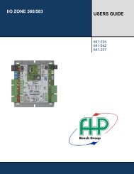
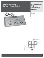
he <strong>CA</strong> Aquarius <strong>Series</strong><br />
Console Units offer the<br />
answer to providing<br />
heating and cooling to<br />
areas where space and access is<br />
limited. Office buildings, hotel/motels,<br />
schools and assisted living complexes<br />
are typical applications where these<br />
are used.<br />
heat pumps<br />
Environmentally friendly with<br />
refrigerant R-410A, the Industries<br />
replacement refrigerant for R-22,<br />
the <strong>CA</strong> <strong>Series</strong> will help qualify your<br />
project for LEEDS certification and<br />
ensure serviceability in the future.<br />
Available in sizes from 3/4 through 1-1/4 tons the <strong>CA</strong> <strong>Series</strong> offers a wide range<br />
of features such as:<br />
High efficiency with rotary compressors.<br />
Slope top design.<br />
Suitable for Geothermal and Tower boiler operation as standard.<br />
Quiet operation.<br />
Multi speed.<br />
Baked powder coated enamel finish on the cabinet. Blends in with most decors.<br />
Available with unit mounted controller with membrane switches,<br />
remote thermostat or master slave operation.<br />
Coated air coil and stainless steel drain pan for corrosion protection.<br />
Easily serviceable with LED fault identification.<br />
Extended cabinet available for ground loop pumping package.<br />
Refrigerant R-410A.<br />
ISO 9001:2000 Certified
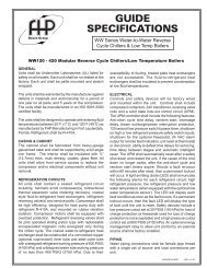
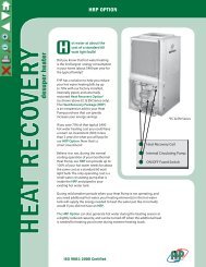
<strong>CA</strong> SERIES<br />
2.875<br />
6.00<br />
RIGHT HAND WATER<br />
CONNECTIONS<br />
LEFT HAND WATER<br />
CONNECTIONS<br />
6.00<br />
6.125<br />
45.00<br />
12.875<br />
48.00 30.75 45.00<br />
23.875<br />
3.375<br />
30.75<br />
11.00<br />
12.00<br />
15.875<br />
48.00<br />
ARI / ISO 13256-1 PERFORMANCE DATA<br />
ENTERING WATER TEMPERATURES<br />
Water Loop Ground Loop Ground Water<br />
86˚F 68˚F 77˚F 32˚F 59˚F 50˚F<br />
<strong>CA</strong>PACITY AND EFFICIENCY DATA<br />
COOLING HEATING COOLING HEATING COOLING HEATING<br />
<strong>CA</strong>PACITY EER <strong>CA</strong>PACITY COP <strong>CA</strong>PACITY EER <strong>CA</strong>PACITY COP <strong>CA</strong>PACITY EER <strong>CA</strong>PACITY COP<br />
(WLHP) (WLHP) (WLHP) (WLHP) (GLHP) (GLHP) (GLHP) (GLHP) (GWHP) (GWHP) (GWHP) (GWHP)<br />
<strong>CA</strong>009 350 2.0 8,200 12.9 9,400 4.6 9,000 16.0 5,400 3.3 10,200 22.3 7,400 3.8<br />
<strong>CA</strong>012 400 2.5 10,500 12.0 12,400 4.3 11,500 14.2 8,400 3.3 13,000 19.4 10,900 3.8<br />
<strong>CA</strong>015 550 4.0 14,400 13.3 15,000 4.3 14,700 14.5 9,800 3.3 16,400 19.8 11,800 3.5<br />
<strong>CA</strong>018 600 5.0 16,400 12.3 17,500 4.2 17,000 14.0 12,000 3.1 18,300 17.6 14,600 3.4<br />
Tabulated performance data is at noted entering water temperatures and entering air conditions of 80.6˚ F DB/66.2˚F WB at<br />
ARI/ISO 13256-1 rated CFM<br />
ENERGY STAR RATED<br />
<strong>FHP</strong> presents the most versatile package in the industry. The extended cabinet option<br />
enables you to use our console units in applications where only Unit Ventilators were<br />
applied before. Using two consoles with the extended cabinet option will compete with<br />
any Geothermal unit ventilator on the market.<br />
<strong>FHP</strong> MANUFACTURING COMPANY<br />
601 N.W. 65TH COURT • FT. LAUDERDALE, FL 33309 • PHONE: (954) 776-5471 • FAX: (800) 776-5529<br />
http://www.fhp-mfg.com<br />
heat pumps<br />
970-195 Rev. 10/08
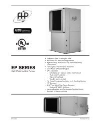
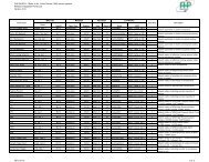
CONSOLE UNIT CONTROLER<br />
CUC SOLID STATE<br />
<strong>FHP</strong> introduces the latest in console solid state control technology. Designed<br />
to enhance the unit operation with more flexibility, accurate control and<br />
operating modes the CUC provides an increased level of comfort in the<br />
conditioned space together with solid state reliability and ease of operation.<br />
The same functions of the proven UPM module are incorporated into the<br />
CUC for unit protection.<br />
CUC controllers are standard on all<br />
<strong>FHP</strong> series CW console units except<br />
for remote and master/slave options.<br />
• Tactile touchpad for<br />
temperature, fan and mode<br />
adjustment.<br />
• Digital display of<br />
temperature in either degrees<br />
Fahrenheit or Celsius.<br />
• LED Display provides<br />
indication for unit operating mode as well as fan speed and fault<br />
indication for high or low pressure lockout.<br />
• Adjustable Temperature Set point from 60° F through 80° F<br />
(15.5° C through 26.7° C ).<br />
• Adjustable Temperature Differential between 1° F and 6° F<br />
(0.6° C and 3.3° C).<br />
• Selectable options<br />
• Manual/Automatic changeover<br />
• Fan speed – High or Low<br />
• Fan operation constant fan or cycling with compressor<br />
• Additional features<br />
• 5 minute anti short cycling delay<br />
• Random start<br />
• 90 second low pressure bypass timer prevents nuisance<br />
lockouts during cold winter start up<br />
• Brownout protection<br />
CUC SOLID STATE<br />
CONSOLE UNIT CONTROLLER<br />
• Intelligent reset allows the unit to automatically restart after 5<br />
minutes if a fault is no longer active<br />
<strong>FHP</strong> MANUFACTURING COMPANY<br />
601 N.W. 65TH COURT • FT. LAUDERDALE, FL 33309 • PHONE: (954) 776-5471 • FAX: (800) 776-5529<br />
http://www.fhp-mfg.com<br />
CUCGW Rev. 11/04
GUIDE<br />
SPECIFI<strong>CA</strong>TIONS<br />
<strong>CA</strong> <strong>Series</strong> R-410A<br />
GENERAL<br />
Units shall be performance certified to ISO standard 13256-1 for Water Loop Heat<br />
Pump, Ground Water Heat Pump and Ground Loop Heat Pump applications. Units<br />
shall be Underwriter Laboratories (UL and ULc) listed for safety on all models.<br />
Each unit shall be run tested at the factory. Each unit shall be pallet mounted and<br />
stretch wrapped. The units shall be warranted by the manufacturer against defects<br />
in materials and workmanship for a period of one year on all parts, and 5 years<br />
on the compressor.<br />
The units shall be designed to operate with entering fluid temperatures between 50˚F<br />
(10˚C) and 110˚F (43.3˚C) in cooling and temperatures between 25˚F (-3.9˚C) and<br />
80˚F (27˚C) in heating as manufactured by <strong>FHP</strong> <strong>Manufacturing</strong> in Fort Lauderdale,<br />
Florida. The units shall be manufactured in an ISO9001:2000 certified facility.<br />
<strong>CA</strong>BINETWORK<br />
Cabinetwork shall include two (2) separate integral assemblies to include: Cabinet<br />
and Sub-base. Cabinet shall be factory fabricated from heavy gauge “paint-grip”<br />
galvanized steel and finished with Polane T Plus polyurethane enamel paint finish.<br />
Cabinet dimensions are in accordance with drawings and are manufactured for<br />
left or right water discharge piping. Cabinet shall be single-piece construction.<br />
Removal of the cabinet shall give complete side and front access to unit for routine<br />
servicing. The cabinet is mounted onto the subbase and secured with two screws<br />
for security. A wall mounting bracket secured to the subbase shall be provided. Air<br />
flow is bottom intake-top discharge. Cabinets will be factory fabricated specifically<br />
for left hand or right hand connections as specified. Cabinet shall be slope top style,<br />
flat top cabinet is not acceptable.<br />
SUB-BASE<br />
Factory mounted 3-3/8" sub-base is constructed of heavy gauge painted steel.<br />
Cutouts are provided for floor connections and outside air. Includes integral filter<br />
mounts to support a bottom mount permanent, washable, aluminum mesh filter.<br />
Sub-base has a bracked that may be secured to the wall to provide stability.<br />
CHASSIS<br />
Chassis is of compact design and of the same dimensions for all model sizes.<br />
Dimensions must match details on drawings. Chassis mounts directly on support<br />
structures provided by the sub-base and shall be removable from the sub-base<br />
without dismantling the sub-base. Both compressor and coil compartments shall<br />
be thermally and acoustically insulated, and have removable steel cover plates<br />
giving double acoustical protection between the two compartments. Compressor<br />
is mounted to the bottom of chassis with a 2 piece base pan to reduce noise<br />
transmission and vibration. The compressor access panel shall have a closed cell<br />
foam insulation for extra quiet operation. Fiberglass insulation is not acceptable on<br />
compressor access panel. The stainless steel condensate drain pan shall be IAQ<br />
with positive slope and be removable without disturbing the evaporator assembly<br />
for cleaning as needed.<br />
REFRIGERANT CIRCUIT<br />
All units shall contain sealed R-410A refrigerant circuit including a hermetic<br />
compressor, finned tube refrigerant to air heat exchanger, four-way solenoid activated<br />
reversing valve, expansion valve refrigerant metering device and coaxial tube-in-tube<br />
water to refrigerant heat exchanger. Compressor shall be high efficiency designed<br />
for heat pump duty and mounted on vibration isolators. Fin-tube refrigerant-toair<br />
exchanger shall be aluminum fin plate and copper tube construction rated to<br />
withstand 450 PSI (3100 kPa) refrigerant working pressure. Coils shall be coated<br />
using an electro coating process for protection against most airbourn chemicals.<br />
Water-to-refrigerant heat exchanger shall be constructed of a convoluted copper<br />
or cupro-nickel inner tube and steel outer tube with a designed refrigerant working<br />
pressure of 450 PSI (3100 kPa) and water side working pressure of no less than<br />
400 PSI (2750 kPa). Four-way solenoid activated refrigerant reversing valve shall<br />
allow heating operation should the solenoid fail to function. All interconnecting<br />
tubing shall be copper. High and low pressure access shall be provided via schrader<br />
style ports.<br />
FAN MOTOR ASSEMBLY<br />
Unit blower is three-speed high efficiency PSC type. Motor is direct connected to<br />
two double width, double inlet forward curved oversized centrifugal blower wheels<br />
that are selected for quiet operation, and balanced to minimize vibration. Blower<br />
wheel access is through removable blower housing covers. Motor and Blower<br />
assembly shall be removable without removing the chassis. Blower CFM is per<br />
scheduled data.<br />
ELECTRI<strong>CA</strong>L<br />
Control circuit shall be 24 volt with direct sensing high and low pressure switches<br />
connected to a normally closed safety circuit. Line voltage control circuit and/or<br />
normally open safety switches are unacceptable. Compressor and blower motors<br />
shall be individually protected against current and/or heat overload. Standard control<br />
options shall be: a) Unit mounted CUC controller incorporating the following features:<br />
Tactile touchpad for temperature, fan and mode adjustment, Digital temperature<br />
display, LED display indicating unit operating mode as well as fan speed and fault<br />
indication, Adjustable temperature set point and differential, Options for manual or<br />
automatic changeover, hi or low fan speed and constant or cycling fan operation,<br />
b) Provisions for a remotely mounted thermostat or c) Provisions for master-slave<br />
connections to other units. The control box will additionally have a compressor<br />
contactor, fan relay, solid state lock-out device and class-2 transformer. The lockout<br />
circuit shall include diagnostic LED's, anti short cycle time delay, random start<br />
time delay and low pressure bypass time delay. A low voltage terminal board is<br />
provided for NEC class-2 connection to units intended for remote thermostat or<br />
master/slave connection only.<br />
POWER CONNECTION<br />
Units shall be provided with a factory mounted 2 x 4 junction box with removable<br />
cover on the same side as the water connections (left or right) for direct wire<br />
connection. This cover may be supplied with a non-fused power disconnect switch<br />
for servicing the unit. The unit shall operate with specified voltages 115v, 208/230v<br />
or 265v, single phase, 60 Hz supply current. Supply power ampacity and maximum<br />
fuse size are per electrical specifications marked on each unit's data plate.<br />
REMOTE THERMOSTAT<br />
Remote thermostat equipped units shall be provided with a 24 volt anticipating<br />
type wall thermostat. a) The thermostat shall be a manual changeover type with<br />
an OFF, HEAT, COOL selector switch and a FAN, AUTO selector switch. b) The<br />
thermostat shall be an auto changeover type with an OFF, AUTO selector switch<br />
and a FAN, AUTO selector switch. A Hi/Lo fan switch shall be unit mounted for fan<br />
speed control.<br />
MASTER-SLAVE<br />
The master-slave operation shall be accomplished with a remote thermostat<br />
operating the master unit. Additional (slave) units shall be connected to the master<br />
unit with the operation of all dictated by the single wall mounted thermostat. A Hi/<br />
Lo fan switch shall be unit mounted for fan speed control. Each unit must have its<br />
own 24 volt transformer.<br />
<strong>CA</strong>BINET OPTIONS<br />
The unit shall be chassis only, chassis on subbase, or chassis with subbase and<br />
cabinet.<br />
PIPING OPTIONS<br />
The unit shall be provided with factory installed supply and return water connection<br />
on right or left side. Supply and return water connections shall be a) 5/8” copper<br />
pipe for field connection of male or female pipe thread b) factory installed 1/2“ FPT<br />
fitting for hose connection c) Factory supplied 1/2” FPT thread and field installed<br />
1/2” x 12” stainless steel hose kit with an automatic flow control valve, ball valves<br />
with P/T ports, y-strainer with blow down valve.<br />
Continuing engineering research results in steady improvements. Therefore, these<br />
ratings and specifications are subject to change without notice.<br />
<strong>CA</strong>SPECS.INDD REV: 12-08
Console Dimensions<br />
<strong>FHP</strong> <strong>Manufacturing</strong> Co.<br />
601 N.W. 65th Court - Fort Lauderdale, FL 33309<br />
Phone: (954) 776-5471 - Fax: (800) 776-5529<br />
http://www.fhp-mfg.com<br />
Fresh Air Opening (In Sub-base Rear)<br />
<strong>CA</strong>UTION! When installing unit in cold climates, an outside<br />
air damper must be provided to prevent possible condenser freeze-up.<br />
<strong>CA</strong>IP.P65 REV: 03-08<br />
NOTES: All dimensions within +/- 0.125".<br />
Filter size: 7" x 30 1/4" x 3/8" Aluminum Mesh<br />
Specifications subject to change without notice.
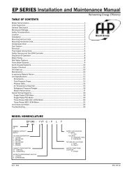
Console Dimensions<br />
63" Extended Cabinet<br />
<strong>FHP</strong> <strong>Manufacturing</strong> Co.<br />
601 N.W. 65th Court - Fort Lauderdale, FL 33309<br />
Phone: (954) 776-5471 - Fax: (800) 776-5529<br />
http://www.fhp-mfg.com<br />
Left Hand Water<br />
Connections<br />
Right Hand Water<br />
Connections<br />
Fresh Air Opening (In Sub-base Rear)<br />
<strong>CA</strong>UTION! When installing unit in cold climates, an outside<br />
air damper must be provided to prevent possible condenser freeze-up.<br />
<strong>CA</strong>IP.P65 REV: 03-08<br />
NOTES: All dimensions within +/- 0.125".<br />
Filter size: 7" x 30 1/4" x 3/8" Aluminum Mesh<br />
Specifications subject to change without notice.
Chassis Dimensions<br />
<strong>FHP</strong> <strong>Manufacturing</strong> Co.<br />
601 N.W. 65th Court - Fort Lauderdale, FL 33309<br />
Phone: (954) 776-5471 - Fax: (800) 776-5529<br />
http://www.fhp-mfg.com<br />
Left Hand Water<br />
Right Hand Water<br />
<strong>CA</strong>IP.P65 REV: 08-07<br />
NOTES: All dimensions within +/- 0.125".<br />
Console units must be installed with a cabinet and sub-base.<br />
Filter size: 7" x 30 - 1/8" x 3/8" Aluminum Mesh.<br />
Unit controller shown, other control options may have a different control panel configuration.<br />
Specifications subject to change without notice.
ELECTRI<strong>CA</strong>L SPECIFI<strong>CA</strong>TIONS<br />
Electrical Elect.<br />
Characteristics Symbol<br />
High 350<br />
Low 320<br />
Compressor Blower Loop Pump Min. Max.<br />
Circuit Fuse/<br />
RLA LRA FLA HP FLA HP Amps Breaker<br />
115-1-60 -0<br />
208/230-1-60 -1 3.7 22.0 0.5 1/10 - - 5.1 15<br />
265-1-60 -2 3.3 16.0 0.8 1/10 - - 5.0 15<br />
BLOWER PERFORMANCE<br />
<strong>CA</strong>PACITY DATA All performance at 350 CFM and 2.0 GPM<br />
COOLING<br />
AQUARIUS CONSOLE UNITS<br />
SPECIFI<strong>CA</strong>TION DATA SHEET<br />
<strong>FHP</strong> MANUFACTURING HIGH-EFFICIENCY WATER SOURCE HEAT PUMPS<br />
ISO 13256-1 CERTIFIED PERFORMANCE DATA Rated at 350 CFM and 2.0 GPM<br />
Water Loop Ground Water Ground Loop<br />
Cooling Heating Cooling Heating Cooling Heating<br />
Capacity EER Capacity COP Capacity EER Capacity COP Capacity EER Capacity COP<br />
8,200 12.9 9,400 4.6 10,200 22.3 7,400 3.8 9,000 16.0 5,400 3.3<br />
Entering Entering Sensible Heat<br />
Fluid Air Total Sensible to Power of<br />
Temp. Temp. Capacity Capacity Total Input Reject EER<br />
( o F) ( o F) (MBtuH) (MBtuH) Ratio (kW) (MBtuH)<br />
50 o<br />
60 o 70 o db<br />
70 o 61 o wb<br />
85 o<br />
100 o<br />
50 o<br />
60 o 75 o db<br />
70 o 63 o wb<br />
85 o<br />
100 o<br />
50 o<br />
60 o 80 o db<br />
70 o 67 o wb<br />
85 o<br />
100 o<br />
50 o<br />
60 o 85 o db<br />
70 o 71 o wb<br />
85 o<br />
100 o<br />
EFT Range (Standard)<br />
45 o F to 110 o F<br />
9.35 6.22 0.67 0.38 10.66 24.4<br />
8.72 5.86 0.67 0.45 10.25 19.5<br />
8.10 5.50 0.68 0.51 9.84 15.9<br />
7.16 4.99 0.70 0.60 9.22 11.8<br />
6.22 4.49 0.72 0.70 8.60 8.9<br />
10.01 7.42 0.74 0.39 11.33 26.0<br />
9.34 6.98 0.75 0.45 10.87 20.8<br />
8.67 6.56 0.76 0.51 10.42 16.9<br />
7.66 5.95 0.78 0.61 9.74 12.6<br />
6.65 5.34 0.80 0.70 9.05 9.5<br />
10.97 8.17 0.74 0.39 12.30 28.2<br />
10.24 7.69 0.75 0.45 11.78 22.6<br />
9.50 7.22 0.76 0.52 11.27 18.4<br />
8.40 6.55 0.78 0.61 10.49 13.7<br />
7.29 5.89 0.81 0.71 9.71 10.3<br />
11.94 8.94 0.75 0.39 13.27 30.5<br />
11.14 8.41 0.75 0.46 12.69 24.4<br />
10.34 7.90 0.76 0.52 12.11 19.8<br />
9.14 7.17 0.78 0.62 11.25 14.8<br />
7.93 6.44 0.81 0.72 10.38 11.1<br />
Units are complete packages containing a compressor, reversing valve, expansion valve metering device, and heat exchangers.<br />
Also included are safety controls: Overload protection for motors, high and low refrigerant pressure switches<br />
and a solid state lock-out circuit. Console units available with unit mounted digital controls including ACO/MCO selection<br />
and LED temperature readout or remote mounted control capability.<br />
Performance based on ARI/ISO rated air flow, fluid flow and voltage. For conditions other than rated, consult the <strong>FHP</strong> EAD<br />
selection software. Due to variations in installation actual performance may vary marginally from tabulated values.<br />
As a result of continuing research and development, specifications are subject to change without notice.<br />
<strong>CA</strong>009IP6 mod1 Rev: 01-09<br />
HEATING<br />
<strong>CA</strong>009<br />
MECHANI<strong>CA</strong>L SPECIFI<strong>CA</strong>TIONS<br />
EFT Range (Standard)<br />
25 o F to 80 o F<br />
Refrigerant: R-410A<br />
Air Coil<br />
Square Rows Tube Fins/<br />
Feet Deep O.D. Inch<br />
2.00 2 3/8 14<br />
Water Coil<br />
Type Work Press<br />
Coaxial 450 psig<br />
Blower Size Compr Type<br />
5.25x8 DD (x2) Rotary<br />
Net Weight Ship Weight<br />
131 lbs 151 lbs<br />
FLUID PRESSURE DROP<br />
Fluid Pressure<br />
Flow Drop<br />
(GPM) (FOH) (PSIG)<br />
1.3 2.16 0.94<br />
1.5 2.80 1.21<br />
2 4.70 2.03<br />
2.5 7.02 3.04<br />
3 9.75 4.22<br />
Entering Entering<br />
Heat<br />
Fluid Air Total Power of<br />
Temp. Temp. Capacity Input Abs. COP<br />
( o F) ( o F) (MBtuH) (kW) (MBtuH)<br />
50 o<br />
7.74 0.53 5.92 4.3<br />
80 o 9.87 0.67 7.60 4.3<br />
60 o<br />
8.90 0.57 6.96 4.6<br />
60<br />
70 o<br />
10.06 0.60 8.00 4.9<br />
80 o<br />
11.22 0.64 9.04 5.2<br />
50 o<br />
7.31 0.54 5.46 3.9<br />
60 o<br />
8.41 0.58 6.43 4.3<br />
70<br />
70 o<br />
9.50 0.61 7.41 4.5<br />
80 o<br />
10.60 0.65 8.38 4.8<br />
50 o<br />
6.81 0.56 4.91 3.6<br />
60 o<br />
7.83 0.59 5.81 3.9<br />
80<br />
70 o<br />
8.85 0.63 6.71 4.1<br />
LOW TEMP HEATING<br />
25 o<br />
30 o 60 o<br />
40 o<br />
25 o<br />
30 o 70 o<br />
40 o<br />
25 o<br />
30 o 80 o<br />
40 o<br />
Antifreeze Required<br />
4.74 0.44 3.22 3.1<br />
5.31 0.46 3.73 3.4<br />
6.45 0.50 4.75 3.8<br />
4.48 0.45 2.93 2.9<br />
5.01 0.47 3.41 3.1<br />
6.09 0.51 4.36 3.5<br />
4.17 0.46 2.59 2.6<br />
4.67 0.48 3.02 2.8<br />
5.67 0.52 3.90 3.2<br />
<strong>FHP</strong> MANUFACTURING COMPANY<br />
601 N.W. 65th Court - Fort Lauderdale, FL 33309<br />
Phone: (954) 776-5471 - Fax: (800) 776-5529<br />
http://www.fhp-mfg.com
ELECTRI<strong>CA</strong>L SPECIFI<strong>CA</strong>TIONS<br />
Electrical Elect.<br />
Characteristics Symbol<br />
High 450<br />
Low 365<br />
Compressor Blower Loop Pump Min. Max.<br />
Circuit Fuse/<br />
RLA LRA FLA HP FLA HP Amps Breaker<br />
115-1-60 -0<br />
208/230-1-60 -1 5.1 28.0 0.5 1/10 - - 6.9 15<br />
265-1-60 -2 4.3 22.0 0.8 1/10 - - 6.2 15<br />
BLOWER PERFORMANCE<br />
AQUARIUS CONSOLE UNITS<br />
SPECIFI<strong>CA</strong>TION DATA SHEET<br />
<strong>FHP</strong> MANUFACTURING HIGH-EFFICIENCY WATER SOURCE HEAT PUMPS<br />
ISO 13256-1 CERTIFIED PERFORMANCE DATA Rated at 450 CFM and 2.5 GPM<br />
Water Loop Ground Water Ground Loop<br />
Cooling Heating Cooling Heating Cooling Heating<br />
Capacity EER Capacity COP Capacity EER Capacity COP Capacity EER Capacity COP<br />
10,500 12.0 12,400 4.3 13,000 19.4 10900 3.8 11,500 14.2 8,400 3.3<br />
<strong>CA</strong>012<br />
MECHANI<strong>CA</strong>L SPECIFI<strong>CA</strong>TIONS<br />
Refrigerant: R-410A<br />
Air Coil<br />
Square Rows Tube Fins/<br />
Feet Deep O.D. Inch<br />
2.00 2 3/8 14<br />
Water Coil<br />
Type Work Press<br />
Coaxial 450 psig<br />
Blower Size Compr Type<br />
5.25x8 DD (x2) Rotary<br />
Net Weight Ship Weight<br />
138 lbs 158 lbs<br />
FLUID PRESSURE DROP<br />
Fluid Pressure<br />
Flow Drop<br />
(GPM) (FOH) (PSIG)<br />
1.5 2.91 1.26<br />
2 4.89 2.11<br />
2.5 7.30 3.16<br />
3 10.14 4.39<br />
4 17.01 7.36<br />
<strong>CA</strong>PACITY DATA All performance at 400 CFM and 2.5 GPM<br />
COOLING<br />
Entering Entering Sensible Heat<br />
Fluid Air Total Sensible to Power of<br />
Temp. Temp. Capacity Capacity Total Input Reject EER<br />
( o F) ( o F) (MBtuH) (MBtuH) Ratio (kW) (MBtuH)<br />
50 o<br />
60 o 70 o db<br />
70 o 61 o wb<br />
85 o<br />
100 o<br />
50 o<br />
60 o 75 o db<br />
70 o 63 o wb<br />
85 o<br />
100 o<br />
50 o<br />
60 o 80 o db<br />
70 o 67 o wb<br />
85 o<br />
100 o<br />
50 o<br />
60 o 85 o db<br />
70 o 71 o wb<br />
85 o<br />
100 o<br />
EFT Range (Standard)<br />
45 o F to 110 o F<br />
11.90 7.92 0.67 0.58 13.88 20.5<br />
11.12 7.46 0.67 0.65 13.35 17.0<br />
10.33 7.02 0.68 0.73 12.82 14.2<br />
9.16 6.39 0.70 0.84 12.02 10.9<br />
7.98 5.76 0.72 0.95 11.23 8.4<br />
12.74 9.44 0.74 0.58 14.73 21.8<br />
11.90 8.89 0.75 0.66 14.15 18.1<br />
11.06 8.37 0.76 0.73 13.56 15.1<br />
9.80 7.61 0.78 0.84 12.69 11.6<br />
8.54 6.86 0.80 0.96 11.81 8.9<br />
13.97 10.40 0.74 0.59 15.98 23.7<br />
13.05 9.80 0.75 0.66 15.31 19.7<br />
12.13 9.22 0.76 0.74 14.65 16.4<br />
10.75 8.39 0.78 0.85 13.65 12.6<br />
9.37 7.56 0.81 0.96 12.66 9.7<br />
15.19 11.37 0.75 0.59 17.22 25.6<br />
14.19 10.71 0.75 0.67 16.48 21.2<br />
13.19 10.08 0.76 0.74 15.73 17.7<br />
11.69 9.17 0.78 0.86 14.62 13.6<br />
10.19 8.27 0.81 0.97 13.51 10.5<br />
Units are complete packages containing a compressor, reversing valve, expansion valve metering device, and heat exchangers.<br />
Also included are safety controls: Overload protection for motors, high and low refrigerant pressure switches<br />
and a solid state lock-out circuit. Console units available with unit mounted digital controls including ACO/MCO selection<br />
and LED temperature readout or remote mounted control capability.<br />
Performance based on ARI/ISO rated air flow, fluid flow and voltage. For conditions other than rated, consult the <strong>FHP</strong> EAD<br />
selection software. Due to variations in installation actual performance may vary marginally from tabulated values.<br />
As a result of continuing research and development, specifications are subject to change without notice.<br />
<strong>CA</strong>012IP6 mod1 Rev: 01-09<br />
HEATING<br />
EFT Range (Standard)<br />
25 o F to 80 o F<br />
Entering Entering<br />
Heat<br />
Fluid Air Total Power of<br />
Temp. Temp. Capacity Input Abs. COP<br />
( o F) ( o F) (MBtuH) (kW) (MBtuH)<br />
50 o<br />
11.05 0.78 8.38 4.1<br />
80 o 12.79 0.91 9.67 4.1<br />
60 o<br />
12.21 0.81 9.43 4.4<br />
60<br />
70 o<br />
13.37 0.84 10.49 4.6<br />
80 o<br />
14.53 0.87 11.54 4.9<br />
50 o<br />
10.44 0.80 7.72 3.8<br />
60 o<br />
11.53 0.83 8.71 4.1<br />
70<br />
70 o<br />
12.63 0.86 9.70 4.3<br />
80 o<br />
13.73 0.89 10.68 4.5<br />
50 o<br />
9.72 0.82 6.94 3.5<br />
60 o<br />
10.74 0.85 7.85 3.7<br />
80<br />
70 o<br />
11.76 0.88 8.76 3.9<br />
LOW TEMP HEATING<br />
25 o<br />
30 o 60 o<br />
40 o<br />
25 o<br />
30 o 70 o<br />
40 o<br />
25 o<br />
30 o 80 o<br />
40 o<br />
Antifreeze Required<br />
7.98 0.70 5.58 3.3<br />
8.55 0.72 6.10 3.5<br />
9.69 0.75 7.13 3.8<br />
7.54 0.72 5.09 3.1<br />
8.08 0.73 5.58 3.2<br />
9.16 0.77 6.54 3.5<br />
7.02 0.73 4.52 2.8<br />
7.52 0.75 4.96 2.9<br />
8.53 0.78 5.85 3.2<br />
<strong>FHP</strong> MANUFACTURING COMPANY<br />
601 N.W. 65th Court - Fort Lauderdale, FL 33309<br />
Phone: (954) 776-5471 - Fax: (800) 776-5529<br />
http://www.fhp-mfg.com
ELECTRI<strong>CA</strong>L SPECIFI<strong>CA</strong>TIONS<br />
Electrical Elect.<br />
Characteristics Symbol<br />
BLOWER PERFORMANCE<br />
High 550<br />
Low 500<br />
AQUARIUS CONSOLE UNITS<br />
SPECIFI<strong>CA</strong>TION DATA SHEET<br />
<strong>FHP</strong> MANUFACTURING HIGH-EFFICIENCY WATER SOURCE HEAT PUMPS<br />
Compressor Blower Loop Pump Min. Max.<br />
Circuit Fuse/<br />
RLA LRA FLA HP FLA HP Amps Breaker<br />
115-1-60 -0<br />
208/230-1-60 -1 6.8 31.2 0.8 1/4 - - 9.2 15<br />
265-1-60 -2 5.8 27.0 0.8 1/4 - - 8.1 15<br />
ISO 13256-1 CERTIFIED PERFORMANCE DATA Rated at 550 CFM and 4.0 GPM<br />
Water Loop Ground Water Ground Loop<br />
Cooling Heating Cooling Heating Cooling Heating<br />
Capacity EER Capacity COP Capacity EER Capacity COP Capacity EER Capacity COP<br />
14,400 13.3 15,000 4.3 16,400 19.8 11,800 3.6 14,700 14.5 9,800 3.3<br />
<strong>CA</strong>015<br />
MECHANI<strong>CA</strong>L SPECIFI<strong>CA</strong>TIONS<br />
Refrigerant: R-410A<br />
Air Coil<br />
Square Rows Tube Fins/<br />
Feet Deep O.D. Inch<br />
2.00 3 3/8 14<br />
Water Coil<br />
Type Work Press<br />
Coaxial 450 psig<br />
Blower Size Compr Type<br />
5.25x8 DD (x2) Rotary<br />
Net Weight Ship Weight<br />
144 lbs 164 lbs<br />
FLUID PRESSURE DROP<br />
Fluid Pressure<br />
Flow Drop<br />
(GPM) (FOH) (PSIG)<br />
2.5 2.51 1.09<br />
3 3.49 1.51<br />
3.5 4.60 1.99<br />
4 5.85 2.53<br />
5 8.74 3.78<br />
<strong>CA</strong>PACITY DATA All performance at 550 CFM and 4.0 GPM<br />
COOLING<br />
Entering Entering Sensible Heat<br />
Fluid Air Total Sensible to Power of<br />
Temp. Temp. Capacity Capacity Total Input Reject EER<br />
( o F) ( o F) (MBtuH) (MBtuH) Ratio (kW) (MBtuH)<br />
50 o<br />
60 o 70 o db<br />
70 o 61 o wb<br />
85 o<br />
100 o<br />
50 o<br />
60 o 75 o db<br />
70 o 63 o wb<br />
85 o<br />
100 o<br />
50 o<br />
60 o 80 o db<br />
70 o 67 o wb<br />
85 o<br />
100 o<br />
50 o<br />
60 o 85 o db<br />
70 o 71 o wb<br />
85 o<br />
100 o<br />
EFT Range (Standard)<br />
45 o F to 110 o F<br />
14.79 9.84 0.67 0.72 17.26 20.5<br />
14.08 9.45 0.67 0.81 16.86 17.3<br />
13.37 9.09 0.68 0.90 16.46 14.8<br />
12.31 8.58 0.70 1.04 15.86 11.8<br />
11.24 8.11 0.72 1.18 15.26 9.6<br />
15.83 11.73 0.74 0.73 18.31 21.8<br />
15.07 11.26 0.75 0.82 17.86 18.4<br />
14.31 10.82 0.76 0.91 17.42 15.7<br />
13.17 10.22 0.78 1.05 16.74 12.6<br />
12.03 9.66 0.80 1.18 16.07 10.2<br />
17.35 12.92 0.74 0.73 19.86 23.7<br />
16.52 12.41 0.75 0.83 19.34 20.0<br />
15.69 11.93 0.76 0.92 18.82 17.1<br />
14.44 11.27 0.78 1.06 18.04 13.7<br />
13.19 10.65 0.81 1.19 17.27 11.1<br />
18.88 14.13 0.75 0.74 21.40 25.5<br />
17.97 13.57 0.75 0.83 20.81 21.6<br />
17.07 13.04 0.76 0.92 20.22 18.5<br />
15.71 12.32 0.78 1.06 19.34 14.8<br />
14.35 11.65 0.81 1.20 18.46 11.9<br />
Units are complete packages containing a compressor, reversing valve, expansion valve metering device, and heat<br />
exchangers. Also included are safety controls: Overload protection for motors, high and low refrigerant pressure switches<br />
and a solid state lock-out circuit. Console units available with unit mounted digital controls including ACO/MCO selection<br />
and LED temperature readout or remote mounted control capability.<br />
Performance based on ARI/ISO rated air flow, fluid flow and voltage. For conditions other than rated, consult the <strong>FHP</strong> EAD<br />
selection software. Due to variations in installation actual performance may vary marginally from tabulated values.<br />
As a result of continuing research and development, specifications are subject to change without notice.<br />
<strong>CA</strong>015IP6 mod1 Rev: 01-09<br />
HEATING<br />
EFT Range (Standard)<br />
25 o F to 80 o F<br />
4.1<br />
Entering Entering<br />
Heat<br />
Fluid Air Total Power of<br />
Temp. Temp. Capacity Input Abs. COP<br />
( o F) ( o F) (MBtuH) (kW) (MBtuH)<br />
50 o<br />
12.75 0.92 9.61<br />
80 o 15.21 1.09 11.50 4.1<br />
60 o<br />
14.26 0.96 10.98 4.3<br />
60<br />
70 o<br />
15.77 1.00 12.36 4.6<br />
80 o<br />
17.28 1.04 13.73 4.9<br />
50 o<br />
12.05 0.94 8.84 3.8<br />
60 o<br />
13.48 0.98 10.13 4.0<br />
70<br />
70 o<br />
14.90 1.02 11.42 4.3<br />
80 o<br />
16.33 1.06 12.71 4.5<br />
50 o<br />
11.22 0.96 7.94 3.4<br />
60 o<br />
12.55 1.00 9.13 3.7<br />
80<br />
70 o<br />
13.88 1.04 10.31 3.9<br />
LOW TEMP HEATING<br />
25 o<br />
30 o 60 o<br />
40 o<br />
25 o<br />
30 o 70 o<br />
40 o<br />
25 o<br />
30 o 80 o<br />
40 o<br />
Antifreeze Required<br />
8.80 0.82 6.00 3.1<br />
9.54 0.84 6.67 3.3<br />
11.02 0.88 8.01 3.7<br />
8.32 0.84 5.46 2.9<br />
9.02 0.86 6.09 3.1<br />
10.41 0.90 7.35 3.4<br />
7.75 0.86 4.82 2.6<br />
8.40 0.88 5.40 2.8<br />
9.70 0.92 6.56 3.1<br />
<strong>FHP</strong> MANUFACTURING COMPANY<br />
601 N.W. 65th Court - Fort Lauderdale, FL 33309<br />
Phone: (954) 776-5471 - Fax: (800) 776-5529<br />
http://www.fhp-mfg.com
ELECTRI<strong>CA</strong>L SPECIFI<strong>CA</strong>TIONS<br />
Electrical Elect.<br />
Characteristics Symbol<br />
BLOWER PERFORMANCE<br />
High 600<br />
Low 550<br />
AQUARIUS CONSOLE UNITS<br />
SPECIFI<strong>CA</strong>TION DATA SHEET<br />
<strong>FHP</strong> MANUFACTURING HIGH-EFFICIENCY WATER SOURCE HEAT PUMPS<br />
Compressor Blower Loop Pump Min. Max.<br />
Circuit Fuse/<br />
RLA LRA FLA HP FLA HP Amps Breaker<br />
208/230-1-60 -1 7.4 33.0 0.8 1/4 10.1 15<br />
265-1-60 -2 5.5 32.0 0.8 1/4 7.7 15<br />
ISO 13256-1 CERTIFIED PERFORMANCE DATA Rated at 600 CFM and 5.0 GPM<br />
Water Loop Ground Water Ground Loop<br />
Cooling Heating Cooling Heating Cooling Heating<br />
Capacity EER Capacity COP Capacity EER Capacity COP Capacity EER Capacity COP<br />
16,400 12.3 17,500 4.2 18,300 17.6 14,600 3.4 17,000 14.0 12,000 3.1<br />
<strong>CA</strong>018<br />
MECHANI<strong>CA</strong>L SPECIFI<strong>CA</strong>TIONS<br />
Refrigerant: R-410A<br />
Air Coil<br />
Square Rows Tube Fins/<br />
Feet Deep O.D. Inch<br />
2.00 3 3/8 14<br />
Water Coil<br />
Type Work Press<br />
Coaxial 450 psig<br />
Blower Size Compr Type<br />
5.25x8 DD (x2) Rotary<br />
Net Weight Ship Weight<br />
144 lbs 164 lbs<br />
FLUID PRESSURE DROP<br />
Fluid Pressure<br />
Flow Drop<br />
(GPM) (FOH) (PSIG)<br />
2.5 1.32 0.57<br />
3 1.83 0.79<br />
3.5 2.42 1.05<br />
4 3.08 1.33<br />
5 4.60 1.99<br />
<strong>CA</strong>PACITY DATA All performance at 600 CFM and 5.0 GPM<br />
COOLING<br />
Entering Entering Sensible Heat<br />
Fluid Air Total Sensible to Power of<br />
Temp. Temp. Capacity Capacity Total Input Reject EER<br />
( o F) ( o F) (MBtuH) (MBtuH) Ratio (kW) (MBtuH)<br />
50 o<br />
60 o 70 o db<br />
70 o 61 o wb<br />
85 o<br />
100 o<br />
50 o<br />
60 o 75 o db<br />
70 o 63 o wb<br />
85 o<br />
100 o<br />
50 o<br />
60 o 80 o db<br />
70 o 67 o wb<br />
85 o<br />
100 o<br />
50 o<br />
60 o 85 o db<br />
70 o 71 o wb<br />
85 o<br />
100 o<br />
EFT Range (Standard)<br />
45 o F to 110 o F<br />
16.26 10.82 0.67 0.91 19.36 17.9<br />
15.65 10.51 0.67 1.01 19.11 15.5<br />
15.05 10.23 0.68 1.12 18.87 13.5<br />
14.14 9.86 0.70 1.27 18.47 11.1<br />
13.23 9.54 0.72 1.43 18.09 9.3<br />
17.40 12.89 0.74 0.91 20.52 19.1<br />
16.76 12.52 0.75 1.02 20.23 16.5<br />
16.11 12.18 0.76 1.12 19.94 14.4<br />
15.13 11.74 0.78 1.28 19.50 11.8<br />
14.16 11.37 0.80 1.44 19.06 9.9<br />
19.08 14.21 0.74 0.92 22.22 20.7<br />
18.37 13.79 0.75 1.03 21.87 17.9<br />
17.66 13.42 0.76 1.13 21.52 15.6<br />
16.59 12.94 0.78 1.29 20.99 12.9<br />
15.52 12.53 0.81 1.45 20.46 10.7<br />
20.76 15.54 0.75 0.93 23.93 22.3<br />
19.98 15.08 0.75 1.03 23.51 19.3<br />
19.21 14.68 0.76 1.14 23.10 16.8<br />
18.04 14.15 0.78 1.30 22.48 13.9<br />
16.88 13.70 0.81 1.46 21.86 11.6<br />
Units are complete packages containing a compressor, reversing valve, expansion valve metering device, and heat exchangers.<br />
Also included are safety controls: Overload protection for motors, high and low refrigerant pressure switches<br />
and a solid state lock-out circuit. Console units available with unit mounted digital controls including ACO/MCO selection<br />
and LED temperature readout or remote mounted control capability.<br />
Performance based on ARI/ISO rated air flow, fluid flow and voltage. For conditions other than rated, consult the <strong>FHP</strong> EAD<br />
selection software. Due to variations in installation actual performance may vary marginally from tabulated values.<br />
As a result of continuing research and development, specifications are subject to change without notice.<br />
<strong>CA</strong>018IP6 mod1 Rev: 10-08<br />
3.9<br />
EFT Range (Standard)<br />
HEATING<br />
25 o F to 80 o F<br />
Entering Entering<br />
Heat<br />
Fluid Air Total Power of<br />
Temp. Temp. Capacity Input Abs. COP<br />
( o F) ( o F) (MBtuH) (kW) (MBtuH)<br />
50 o<br />
15.37 1.16 11.39<br />
80 o 17.74 1.31 13.27 4.0<br />
60 o<br />
16.96 1.19 12.89 4.2<br />
60<br />
70 o<br />
18.56 1.22 14.38 4.4<br />
80 o<br />
20.16 1.25 15.88 4.7<br />
50 o<br />
14.52 1.19 10.47 3.6<br />
60 o<br />
16.03 1.22 11.87 3.9<br />
70<br />
70 o<br />
17.54 1.25 13.28 4.1<br />
80 o<br />
19.04 1.28 14.68 4.4<br />
50 o<br />
13.52 1.21 9.37 3.3<br />
60 o<br />
14.93 1.25 10.67 3.5<br />
80<br />
70 o<br />
16.33 1.28 11.97 3.7<br />
LOW TEMP HEATING<br />
25 o<br />
30 o 60 o<br />
40 o<br />
25 o<br />
30 o 70 o<br />
40 o<br />
25 o<br />
30 o 80 o<br />
40 o<br />
Antifreeze Required<br />
11.15 1.09 7.43 3.0<br />
11.93 1.11 8.16 3.2<br />
13.50 1.13 9.63 3.5<br />
10.54 1.11 6.74 2.8<br />
11.27 1.13 7.43 2.9<br />
12.75 1.16 8.81 3.2<br />
9.81 1.14 5.93 2.5<br />
10.50 1.15 6.57 2.7<br />
11.88 1.18 7.84 2.9<br />
<strong>FHP</strong> MANUFACTURING COMPANY<br />
601 N.W. 65th Court - Fort Lauderdale, FL 33309<br />
Phone: (954) 776-5471 - Fax: (800) 776-5529<br />
http://www.fhp-mfg.com