Operating manual for Mini-Automatic sprayvalve MMFS
Operating manual for Mini-Automatic sprayvalve MMFS
Operating manual for Mini-Automatic sprayvalve MMFS

Create successful ePaper yourself
Turn your PDF publications into a flip-book with our unique Google optimized e-Paper software.
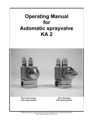
<strong>Operating</strong> <strong>manual</strong><br />
<strong>for</strong><br />
<strong>Mini</strong>-<strong>Automatic</strong><br />
<strong>sprayvalve</strong> <strong>MMFS</strong><br />
Read this <strong>manual</strong> carefully be<strong>for</strong>e installing, operating or servicing this equipment.<br />
Keep always handy <strong>for</strong> further use.
1 Introduction<br />
The <strong>Mini</strong>-<strong>Automatic</strong> <strong>sprayvalve</strong> <strong>MMFS</strong> is designed and constructed <strong>for</strong> application of thin materials f.i.<br />
release agents, colours or other fluids of low viscosity. This <strong>sprayvalve</strong> sprays in roundspray.<br />
Depending on viscosity of fluid, the application can be adjusted individually via nozzle dimension,<br />
atomizing air pressure and material pressure. The supply of atomizing air, control air and material<br />
should be done via three hoses. Spray valves are precision tools. Always keep clean and observe<br />
minimum instructions to maintain a long usefull life of the valves.<br />
2 Safety<br />
2.1 Duties of the user<br />
• The user must read this service <strong>manual</strong> carefully be<strong>for</strong>e per<strong>for</strong>ming any operations.<br />
• Application and service operations should not be carried out if the user is not absolutely sure of<br />
the purpose and consequence of the operations.<br />
2.2 Definitive Use<br />
The <strong>Mini</strong>-<strong>Automatic</strong> <strong>sprayvalve</strong> <strong>MMFS</strong> is a pneumatically controlled <strong>sprayvalve</strong>. It is suitable <strong>for</strong><br />
continuously or intermittent use. It is not suitable <strong>for</strong> spraying aggressive fluids like acid, alkaline<br />
solutions, cleaning agents, chemicals etc.. In case of doubt, please contact the manufacturer.<br />
2.3 Warning against danger<br />
This operating <strong>manual</strong> warns users of operations which may put their health at risk. The warnings are<br />
indicated by combinations of text and symbols corresponding to the different danger classes.<br />
WARNING!<br />
Signs a possible dangerous situation.<br />
If you don´t avoid, death or severe injuries can follow.<br />
CAUTION!<br />
Indicates a situation which may be dangerous.<br />
Failure to heed the caution may result in personal injury. This indication is also used where material<br />
damage is possible.<br />
IMPORTANT!<br />
Indicates tips <strong>for</strong> usage and other helpful in<strong>for</strong>mation.<br />
3 Function Description<br />
The <strong>Mini</strong>-<strong>Automatic</strong> <strong>sprayvalve</strong> <strong>MMFS</strong> is pneumatically controlled: air open; spring return.<br />
The spraying material is to be fed to the valves via pressure tank or pump. The separate controlled<br />
atomizing air atomizes the material to a spray jet. This <strong>sprayvalve</strong> sprays in a very fine round spray jet.<br />
4 Installation<br />
The <strong>MMFS</strong> can be installed in any position. Vibrations of the valve caused by fast intermitting cycles<br />
require solid and massive installation. For solid attachment the use of mounting (9.1.0) is recommend.<br />
Distance to spraying surface varies of application. Vibration of the equipped machine to the valve<br />
should be limited as far as possible.
4.1 Hose connection and assembly<br />
Connect hoses <strong>for</strong> atomizing air and control air to separately control valves (pressure reducers and<br />
solenoids). Then fluidhose to material pressure tank or other means of feeding fluid as under:<br />
• atomizing air (Z) (hose blue):<br />
Ł to 2/2 way solenoid<br />
• control air (S) (hose black):<br />
Ł to 3/2 way solenoid<br />
• fluid (M) (hose transparent):<br />
Ł to feeding device<br />
The three hoses are fixed by the mounting (9.1.0). To assembly new hoses to the spray valve, unscrew<br />
ratchet assembly (10.0.3). Then take off the mounting with hoses. Connect new hoses to the hose<br />
sockets (11.1.0) and put hose sockets into the valve body (4.1.0). Assemble mounting (9.1.0) with<br />
correct side to the valve body (4.1.0).<br />
IMPORTANT !<br />
Nozzle and needle can be damaged. Be<strong>for</strong>e adjusting ratchet assembly to the valve body,<br />
please turn (open) regulating knob (10.1.1) anti-clockwise.<br />
Turn (open) regulating knob anti-clockwise and screw in the ratchet assembly (10.0.3). Connect fitting<br />
(13.0.0) <strong>for</strong> control air and fittings (13.0.1) <strong>for</strong> material and atomizing air to the hoses.<br />
4.2 <strong>Operating</strong> instructions<br />
CAUTION !<br />
Never point the sprayjet against persons. Wearing eye protection is strongly recommended.<br />
Spraying procedures cause noises depending on the used pressure. If necessary, wearing of<br />
ear protection is recommend.<br />
WARNING !<br />
Danger caused by combustible and noxious spraying material. Safety instructions on fluid can<br />
and material data of fluid manufacturer must definitely be observed.<br />
The valve <strong>MMFS</strong> needs at least 5 bar control air pressure. The atomizing air should be 0,2 – 6 bar. The<br />
maximum material pressure in standard version is 4 bar. For higher material pressures or using long<br />
hose length the use of mounting ¼” (9.1.1) is needed. In any case, please observe the regulations of<br />
the professional/trade association having liability <strong>for</strong> industrial safety and insurance.<br />
When you are certain, that fluid pressure stands up to the nozzle, actuate 2/2 way solenoid <strong>for</strong><br />
atomizing air. After that actuate 3/2 way solenoid <strong>for</strong> control air. This way you reveive socalled “pre-air”<br />
prior to opening fluid flow. After each cycle solenoids are to actuate in reverse order, so you will still<br />
have “purging-air” after needle has closed nozzle and fluid flow was stopped. This prevent fluid to <strong>for</strong>m<br />
out drops instead of being atomized.<br />
Set atomizing air pressure and fluid pressure according to required spray droplet sizes. Two separate<br />
pressure reducers must be available. Intermittend use as well as continuous use is possible.<br />
Standard version of valve has round spray jet. Depending on viscosity of fluid, nozzle diameters are<br />
available in 0,3 / 0,5 / 0,8 / 1,0 / 1,2 / 1,5 / 2,0mm ∅. The travel of needle is giving way to fluid as<br />
adjusted by the regulating knob (10.1.1). Turning this knob in anti-clockwise turn = more fluid;<br />
clockwise turn = less fluid.<br />
One revolution of regulating knob (10.1.1) gives 0,5mm more or less stroke. Do not over-tight the<br />
regulating knob.<br />
IMPORTANT !<br />
The maximum fluid outlet is already reached, when no further ratchets are noticeable. Do not<br />
turn the regulating knob (10.1.1) in anti-clockwise turn any further.
IMPORTANT !<br />
To avoid damages to nozzle and needle adjust decrease of fluid flow (turning regulating knob<br />
10.1.1 clockwise) only when fluid is emitted from the nozzle. This is the only way to observe<br />
the steady reduction of fluid flow until an absolute stop of fluid. Going on to turn the regulating<br />
knob clockwise would at once push the needle into the nozzle to such an extant that both parts<br />
could be damages. This applies expecially to valves where needle regulation is execute by<br />
hexagon key (special design, not shown in sectional drawing).<br />
It is harmless to leave fluid within the valve (no connection to outside air), if system stays under<br />
pressure.<br />
5 Repair and Maintance<br />
Be<strong>for</strong>e starting maintenance or repair work, ensure that all air operated tools are disconnected from the<br />
air supply.<br />
WARNING !<br />
Danger caused by combustible and noxious spraying material. Safety instructions on fluid can<br />
and material data of fluid manufacturer must definitly be observed.<br />
WARNING !<br />
Be<strong>for</strong>e opening the spray valve it has to be disconnected from the air and fluid supply.Otherwise<br />
ejected elements can cause danger.<br />
The <strong>sprayvalve</strong> is a high precision tool. Always keep clean and observe minimum instructions to<br />
maintain a long and useful life of valve. We recommend lubricating moveable parts regularly, and<br />
greasing threads, especially the nozzle threads, when replacing or cleaning the nozzle. It is<br />
recommended to use clean and filtered application fluid only. Also atomizing air should be clean.<br />
Control air should be slightly oiled.<br />
5.1 Cleaning<br />
To clean valve, spray solvent until pure solvent leaves nozzle. Do not submerge entire valve in solvent.<br />
At longer working interruptions it is advisable to clean air cap and nozzle by putting these parts only<br />
into solvent. If necessary use a soft brush. Moving parts and threads should alway be greased slightly.<br />
The spray valve should be cleaned using an appropiate thinner. To clean small drill holes, use our<br />
special nozzle cleaning needles.<br />
5.2 Trouble shooting<br />
• If drops <strong>for</strong>m on the retainer (6.1.0), the packing set (5.0.0) is worn out. To exchange gaskets,<br />
remove needle (see “4.3 changing nozzle set”). Then unscrew retainer (6.1.0) and change<br />
packing set (5.0.0).<br />
Re-assamble in reverse order. The o-rings (6.2.0) and (7.4.0) are to be renewed if uncontrolled<br />
air blow is noticeable.<br />
• If drops <strong>for</strong>m on the nozzle (2.1.0), either needle or nozzle is worn and should be replaced. Or<br />
needle is not closing properly f.i. because of particle residues within nozzle.<br />
• If there is an uneven and not steady spray jet: Make sure that nozzle (2.1.0) is screwed in tight.<br />
Other reason could also be dirt residue within air cap (chapter “4.1 cleaning”).<br />
5.3 Changing the nozzle set<br />
A nozzle set includes needle (7.0.0), nozzle (2.1.0) and air cap (1.1.0)<br />
If nozzle size is to be changed, always change all three parts. Change the complete set also when only<br />
one of the parts is defect. Be<strong>for</strong>e starting maintenance or repair work, ensure that all air operated tools<br />
are disconnected from the air supply.
• Remove ratchet assembly (10.0.3)<br />
• Remove mounting (9.1.0) and hoses<br />
• Pull out needle spring (8.1.0)<br />
• Pull out needle (7.0.0)<br />
• Remove air cap (1.1.0) and unscrew nozzle (2.1.0)<br />
Be<strong>for</strong>e unscrewing nozzle, please observe that needle never is under spring pressure.<br />
RE-ASSAMBLE IN REVERSE ORDER.<br />
Please observe chapter “3.1 hose connection”.<br />
Needle nuts (7.2.0) must be counter-screwed in such a position where “pre- and purging-air” works<br />
according to chapter “3.2 operating instructions”.<br />
5.4 Changing gaskets<br />
IMPORTANT !<br />
Do not use metallical aid to remove and insert gaskets and gasket seats !<br />
Gaskets and gasket seats can be damaged.<br />
Be<strong>for</strong>e starting maintenance or repair work, ensure that all air operated tools are disconnected from the<br />
air supply.<br />
• Remove ratchet assembly (10.0.3)<br />
• Remove mounting (9.1.0) and hoses<br />
• Pull out needle spring (8.1.0)<br />
• Pull out needle (7.0.0)<br />
• Unscrew retainer (6.1.0)<br />
Pull out gaskets. New gaskets should be greased slightly. O-Ring (6.2.0) is to be placed into the<br />
retainer (6.1.0). O-ring (5.2.0) is to be placed into the seat of the retainer. After that insert shaped<br />
gasket (5.1.0) into the center of o-ring (5.2.0). The shaped gasket (5.1.0) is not symmetrical. The<br />
somewhat wider opening must be positioned to point to the front of spray valve i.e. after assembling<br />
retainer in direction “nozzle”. When inserting o-rings and gaskets, do not use any sharp or pointed<br />
metallic implements. Mainly the gasket as a very precise and sensitive component is not able to stand<br />
impacts. Completed retainer (6.0.0) slightly greased then is put back into valve body (4.1.0). RE-<br />
ASSAMBLE IN REVERSE ORDER.<br />
ca. 114<br />
76<br />
86<br />
10<br />
33<br />
13<br />
t=15<br />
30<br />
ca. 50
3.1.0<br />
1.1.0<br />
2.1.0<br />
4.1.0<br />
5.4.0<br />
5.1.0<br />
5.2.0<br />
6.1.0<br />
6.2.0<br />
7.1.0<br />
7.2.0<br />
7.3.0<br />
7.4.0<br />
7.2.0<br />
8.1.0<br />
10.0.3<br />
11.2.0<br />
11.1.0<br />
12.1.2<br />
13.0.1<br />
11.2.0<br />
9.1.0<br />
12.1.1<br />
12.1.0<br />
11.2.0<br />
11.0.1<br />
9.1.1<br />
11.1.2<br />
13.0.0<br />
13.0.1<br />
Sonderausführung Materialanschluß R 1/4"
6. Spareparts<br />
draw-no. part-no. Qty. Description<br />
1.1.0 * 1 air cap, round spray (part-no. see overleef)<br />
2.1.0 * 1 nozzle, stainless steel (part-no. see overleef)<br />
3.1.0 410040 1 collar ring<br />
4.1.0 510032 1 valve body<br />
5.0.0 640105 1 packing set<br />
5.1.0 640103 1 shaped gasket<br />
5.2.0 640027 1 o-ring<br />
5.4.0 640104 1 plastic protection cover<br />
6.0.0 810016 1 retainer, complete<br />
6.1.0 810015 1 retainer<br />
6.2.0 640026 1 o-ring<br />
7.0.0 * 1 needle, complete (part-no. see overleef)<br />
7.1.0 * 1 needle, stainless steel (part-no. see overleef)<br />
7.2.0 410041 2 needle nut<br />
7.3.0 710007 1 piston<br />
7.4.0 640001 1 o-ring<br />
8.1.0 820020 1 needle spring<br />
9.1.0 910016 1 mounting<br />
9.1.1 910017 1 mounting 1/4"<br />
10.0.3 900006 1 ratchet assembly, complete<br />
10.1.1 610088 1 regulating knob with spring and pin<br />
10.2.1 640106 1 lock<br />
11.0.0 220096 3 hose socket, complete<br />
11.1.0 220094 3 hose socket<br />
11.2.0 640068 3 o-ring<br />
11.0.1 320097 1 hose socket, complete<br />
11.1.1 320096 1 hose socket<br />
11.2.0 640068 2 o-ring<br />
11.1.2 610064 1 dobble nipple 1/4" - 1/8"<br />
12.1.0 340006 1m hose, black (control air)<br />
12.1.1 340007 1m hose, translucent (fluid)<br />
12.1.2 340005 1m hose, blue (atomizing air)<br />
13.0.0 220034 1 fitting 1/8"<br />
13.0.1 220023 2 fitting 1/4"<br />
* part-no. see next page.<br />
When ordering nozzles, needles and air caps, please indicate nozzle dimension.<br />
Available dimensions: 0,3 / 0,5 / 0,8 / 1,0 / 1,2 / 1,5 and 2,0mm ∅ other dimensions on request.<br />
In standard version all o-rings are made from viton.
6.1 Part-no. <strong>for</strong> needles, nozzles and air caps<br />
*needle, complete<br />
*needle<br />
draw-no. part-no. Description draw-no. part-no. Description<br />
7.0.0 110200 0,3mm 7.1.0 110193 0,3mm<br />
7.0.0 110201 0,5mm 7.1.0 110194 0,5mm<br />
7.0.0 110202 0,8mm 7.1.0 110195 0,8mm<br />
7.0.0 110203 1,0mm 7.1.0 110196 1,0mm<br />
7.0.0 110204 1,2mm 7.1.0 110197 1,2mm<br />
7.0.0 110205 1,5mm 7.1.0 110198 1,5mm<br />
7.0.0 110206 2,0mm 7.1.0 110199 2,0mm<br />
*nozzle<br />
draw-no. part-no. Description<br />
2.1.0 210057 0,3mm<br />
2.1.0 210058 0,5mm<br />
2.1.0 210059 0,8mm<br />
2.1.0 210060 1,0mm<br />
2.1.0 210061 1,2mm<br />
2.1.0 210062 1,5mm<br />
2.1.0 210127 2,0mm<br />
* air cap, round spray 15°<br />
draw-no. part-no. Description<br />
1.1.0 310092 <strong>for</strong> nozzle 0,3 - 0,5mm<br />
1.1.0 310093 <strong>for</strong> nozzle 0,8 - 1,0mm<br />
1.1.0 310094 <strong>for</strong> nozzle 1,2 - 1,5mm<br />
1.1.0 310095 <strong>for</strong> nozzle 2,0mm<br />
7. Technical data<br />
measurements with mounting<br />
measurements without mounting<br />
weight<br />
air consumption<br />
pressure <strong>for</strong> control air<br />
pressure <strong>for</strong> atomizing air<br />
pressure <strong>for</strong> material<br />
= 115mm x 15mm x 50mm<br />
= 115mm x 15mm x 30mm<br />
= ca. 275g (without hoses)<br />
= ca. 38,3 ltr. (at 3 bar and 1,0mm nozzle)<br />
= 5 – 6 bar<br />
= 0,2 – 8 bar<br />
= max. 4 bar (<strong>for</strong> higher pressure spezial design available)<br />
Special designs on request. Technical alterations reserved. December 2000<br />
8. Manufacturer declaration<br />
The spray valve <strong>MMFS</strong> was constructed and produced by<br />
ALFRED SCHÜTZE Apparatebau GmbH, Hannoversche Straße 69-71, 28309 Bremen-Germany<br />
in accordance with the guidelines and standards of DIN EN 292. This spray valve can be combined<br />
with other modules or machines, which comply to DIN EN 292, without limiting the con<strong>for</strong>mity.<br />
Ort Datum Unterschrift des Herstellers<br />
Bremen 01.12.2000