FLEXICHEVRON® Mist Eliminators for Flue Gas ... - Koch-Glitsch
FLEXICHEVRON® Mist Eliminators for Flue Gas ... - Koch-Glitsch
FLEXICHEVRON® Mist Eliminators for Flue Gas ... - Koch-Glitsch

Create successful ePaper yourself
Turn your PDF publications into a flip-book with our unique Google optimized e-Paper software.
KOCH FLEXICHEVRON ® MIST<br />
ELIMINATORS IN UTILITY,<br />
REFINERY, AND OTHER<br />
INDUSTRIAL FGD SERVICES<br />
FGD Application<br />
<strong>Koch</strong> designs and manufactures a variety of products<br />
<strong>for</strong> flue gas desulfurization (FGD) applications. FGD<br />
applications are relevant to large electrical power<br />
producers, kiln flue gas <strong>for</strong> cement production, potline<br />
flue gas <strong>for</strong> aluminum or other metal foundries, flue<br />
gas from FCC units in refineries, or other power or<br />
process flue gasses which require SO 2 removal.<br />
Processes vary depending on the amount of SO 2<br />
involved, the solution being used to absorb the SO 2 ,<br />
and the particular equipment used in the absorption<br />
tower. The most common process is using lime/limestone<br />
slurry FGD systems. Chemistry <strong>for</strong> this particular<br />
process involve a lime or limestone slurry which<br />
consists of a solution of calcium compound solids in<br />
suspension as well as calcium salts (sulfites and sulfates)<br />
in solution. These dissolved compounds are<br />
generally not a significant problem unless the solution<br />
is saturated. In this case, as free Ca ++ ions and SO 2 (aq)<br />
continue to react, the resulting products are calcium<br />
sulfite and sulfate in varying proportions depending<br />
upon operating pH as well as other factors. The additional<br />
reaction of Ca ++ with CO 2 in the absorber <strong>for</strong>m<br />
carbonate products, which will occur to a minor extent<br />
at low pH. At a pH above 8, significant carbonation<br />
occurs due to free calcium hydroxide in the absorber.<br />
This results in carbonate deposition on the internals,<br />
including the mist eliminators.<br />
As the sulfite, sulfate, and carbonate compounds are<br />
<strong>for</strong>med in a supersaturated solution, precipitates are<br />
<strong>for</strong>med adding to the suspended solids level and scaling<br />
potential. Additives such as magnesium, sulfur,<br />
and dibasic acid (DBA) allow one to operate in an<br />
"inhibited oxidation" state, preventing precipitate deposition<br />
on equipment and mist eliminators.<br />
It quickly becomes apparent that there are a number<br />
of variables affecting the equilibrium of reaction within<br />
the system. The main components <strong>for</strong> concern, in<br />
the mist eliminator zone, are calcium sulfite and calcium<br />
sulfate. The sulfite precipitates out as a soft, white<br />
material which is easily washed from any surface on<br />
which it settles. Calcium sulfate is a hard and difficult<br />
to remove compound. Once the sulfate precipitate<br />
has initially taken hold, wether it be in crevices, hidden<br />
zones, or rough area in general, further precipitation<br />
continues more rapidly.<br />
FLEXICHEVRON ®<br />
General Design<br />
Some applications with lower SO 2<br />
concentrations may warrant only one<br />
chevron level due to lower L/G ratios,<br />
or other unique tower geometries.<br />
However, <strong>for</strong> the majority of applications,<br />
the mist elimination zone is<br />
frequently made up of two stages of<br />
mist eliminators. This two stage<br />
design normally applies to either<br />
vertical flue gas flow or horizontal<br />
flue gas flow. The lower, or first<br />
stage mist eliminator is often referred<br />
to as the "roughing" or "bulk entrainment<br />
separator". It is typically characterized<br />
by a high capacity, open design<br />
with the intent on removing as much liquid<br />
as possible. Typically, this chevron level<br />
is irrigated intermittently from both the top and<br />
the bottom.<br />
The second stage mist eliminator operates drier, is<br />
generally more efficient relative to the first stage, and<br />
is typically irrigated intermittently from the bottom<br />
only. At times, users may elect to have a top spray <strong>for</strong><br />
the upper level mist eliminator, to periodically flush<br />
the system during low demand periods, or unit outages.<br />
Care must be taken to "balance" the per<strong>for</strong>mance<br />
of the two mist eliminator stages as each impact<br />
the per<strong>for</strong>mance of the other. Selecting a first stage<br />
ME that is too "open" will result in too much slurry getting<br />
to the second stage, and potentially plug and create<br />
a cleaning issue. Selecting a first stage that is too<br />
restrictive may also result in potential cleaning issues,<br />
due to the shear volume of solids at the first stage<br />
level. Whether it be the first stage or the second stage<br />
mist eliminator , both levels offer a clean profile, free<br />
of any hooks or grooves that can accumulate solids<br />
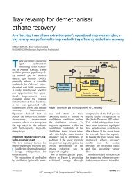
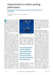
buildup or impede washing. In essence, a "hydraulic<br />
hook" is created between chevron blades due to high<br />
and low pressure gradients. This hydraulic hook creates<br />
the same effect as a physical hook, i.e. a disengaging<br />
point to allow <strong>for</strong> liquid drainage, without the<br />
pluggage risk normally associated with using a real<br />
hook.<br />
Hydraulic Hook<br />
FLOW DIRECTION<br />
Hydraulic Hook<br />
Pressure contours using CFD reflects low pressure<br />
areas resulting in liquid accumulation.<br />
1
Capacity<br />
Moisture Carry Over<br />
Mechanical<br />
Integrity<br />
PROBLEM<br />
FREE<br />
DESIGN<br />
Pressure Drop<br />
Fouling Resistance & Cleaning<br />
FLEXICHEVRON ® <strong>Mist</strong> <strong>Eliminators</strong><br />
<strong>Koch</strong>-Otto York Design Pentagon<br />
Customer requirements are such that <strong>Koch</strong><br />
designs need to meet a multitude of requirements.<br />
For this reason, we have developed a "design<br />
pentagon" which ensures no detail will be overlooked<br />
in the FGD design<br />
FLEXICHEVRON ® Polypropylene Polypropylene Polypropylene Polysulfone FRP Stainless<br />
w/5% Glass w/20% Glass Steel<br />
Style VIII 170 185 200 300 300 350+<br />
Style XII/XIV 170 185 200 300 300 350+<br />
Style XXVII 170 185 200 n/a n/a n/a<br />
Style XXVIII 170 185 200 n/a n/a n/a<br />
Temperature in degrees fahrenheit<br />
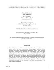
Materials of construction vary widely depending on the customer’s preferences, operating conditions, amount<br />
of chlorides in the flue gas, maintenance requirements, and ultimate product cost. For this reason, <strong>Koch</strong> offers<br />
a variety of materials with the following continuous operating temperatures, when properly supported.<br />
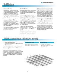
<strong>Flue</strong> gas<br />
from Boiler<br />
By-pass<br />
damper<br />
Recycle fan<br />
Stack<br />
Booster fan<br />
<strong>Gas</strong><br />
reheat<br />
Process Water<br />
MIST ELIMINATORS<br />
Primary<br />
hydrocyclones<br />
Secondary<br />
hydrocylones<br />
Process Water<br />
Splitter box<br />
Centrifuge<br />
Absorber<br />
Gypsum to<br />
store<br />
Limestone<br />
from store<br />
Limestone<br />
silo<br />
Oxidation air<br />
compressor<br />
Gypsum<br />
feed tank<br />
Secondary<br />
hydrocyclone<br />
feed tank<br />
Centrifuge<br />
feed tank<br />
Water<br />
treatment<br />
chemicals<br />
Ball Mill<br />
Limestone slurry<br />
buffer tank<br />
Purge break<br />
tank<br />
Centrate<br />
tank<br />
Water treatment<br />
plant<br />
Treated effluent<br />
to discharge<br />
Sludge<br />
<strong>for</strong> disposal<br />
Limestone/Gypsum FGD plant - Process flow schematic<br />
2
Spray Wash Design<br />
<strong>for</strong> FGD Systems<br />
<strong>Koch</strong> has designed and supplied innumerable FLEXI-<br />
CHEVRON ® mist eliminators <strong>for</strong> many applications<br />
<strong>for</strong> evaporators, process engineering, and air pollution<br />
control. Although a benefit of chevron type mist<br />
eliminators is their resistance to fouling and pluggage,<br />
it is frequently necessary to include irrigation<br />
of the chevron. Otherwise, as material builds up on<br />
the chevron blades, local velocities increase due to<br />
less open area. This substantially increases pressure<br />
drop proportional to gas V 2 and may result in reentrianment<br />
of collected droplets. Irrigation is<br />
required in the majority of FGD applications.<br />
• Recommended slurry recycle in the wash water<br />
should not exceed 50%.<br />
• A typical irrigation rate is 2.5 m 3 /hr/m 2 of<br />
chevron cross section.<br />
• Wash nozzles are typically mounted about<br />
500mm from the near face of the chevron<br />
(vertical flow applications).<br />
• Recommended wash water frequency should be a<br />
minimum of 60 seconds per hour.<br />
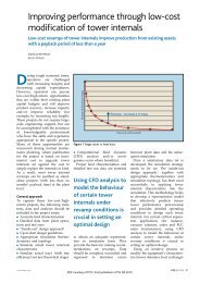
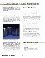
ROTAMETER<br />
SPRAY<br />
NOZLE<br />
SLURRY<br />
PI<br />
AIR<br />
IN<br />
TAKE<br />
MIST<br />
SEALED PORT FOR<br />
VANE ANEMOMETER<br />
TEST CHEVRON<br />
U-TUBE<br />
MANOMETER<br />
EXHAUST<br />
FAN<br />
FLEXICHEVRON ®<br />
FLEXICHEVRON ®<br />
PI<br />
COMPRESSED<br />
AIR<br />
LIME<br />
SLURRY TANK<br />
SLURRY PUMP<br />
Test system <strong>for</strong> checking plugging resistance of<br />
10,500 mm<br />
FLEXICHEVRON ® Side view of a two stage FLEXICHEVRON ®<br />
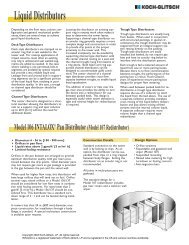
Some mist eliminators are more resistant to fouling<br />
than others. Those with narrow blade spacings, or<br />
with more tortuous gas streams, were prone to more<br />
fouling as well as more difficult to accommodate<br />
wash water spray patterns. Hooks on a chevron in<br />
fouling service are ineffective as they quickly bridge<br />
over with solids. In comparative tests with other<br />
chevron products, FLEXICHEVRON ® products were<br />
especially resistant to fouling and solids build up.<br />
The essential requirement of effective chevron<br />
washing can be summarized as follows:<br />
• The design of the chevron must be such that the<br />
wash liquor can reach all parts of the chevron<br />
where fouling may accumulate. Braces or other<br />
structural members must be designed to minimize<br />
interference with wash spray patterns.<br />
• Spray nozzles should be full cone, 90º - 120º<br />
spray angles.<br />
•Maintain wash water pressure at 2 bar minimum.<br />
• Spray pattern coverage of the chevron should be<br />
150% of chevron cross sectional area.<br />
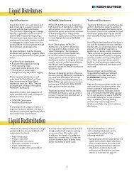
5400 mm<br />
Liquid<br />
Sump<br />
and Washing System in a horizontal flow duct<br />
Wash Nozzles<br />
3
Exact frequencies and wash water volumes can best<br />
be determined from plant experience, overall water<br />
balance required <strong>for</strong> the absorber, and total available<br />
wash water. The <strong>Koch</strong> applications engineer<br />
can tailor the design to specific customer requirements.<br />
Upper Spray wash Header<br />
FLEXICHEVRON ®<br />
3300 mm<br />
Intermediate Spray wash Header FLEXICHEVRON ®<br />
Lower Spray wash Header<br />
Side view of a two stage FLEXICHEVRON ® and Washing System in a vertical tower.
<strong>Koch</strong> FLEXICHEVRON ®<br />
<strong>Mist</strong> <strong>Eliminators</strong> <strong>for</strong> the<br />
FGD Industry<br />
<strong>Koch</strong> offers many types of chevron mist eliminators<br />
to facilitate the numerous styles of absorbers and<br />
internal support arrangements.<br />
FLEXICHEVRON ® Style VIII<br />
<strong>Mist</strong> <strong>Eliminators</strong><br />
Multi purpose mist eliminators designed specifically<br />
<strong>for</strong> FGD absorbers where fouling, ease of cleaning<br />
low pressure drop, and dependability are important.<br />
The Style VIII continues to occupy the majority of<br />
<strong>Koch</strong> FGD applications due to its rugged construction<br />
and low moisture carryover. The Style VIII can<br />
be used in either vertical or horizontal gas flow. The<br />
Style VIII can be either a single stage or multi stage<br />
application and is available in stainless<br />
steel, polyproylene, polysulfone,<br />
noryl, or<br />
fiberglass.<br />
FLEXICHEVRON ® Style XXVII<br />
<strong>Mist</strong> <strong>Eliminators</strong><br />
This mist eliminator combines excellent efficiency<br />
and strength at an economical price. The Style XXVII<br />
can be either a single stage or multi stage application<br />
and comes in standard vane spacing of 1.625”,<br />
1.125”, or 0.875”. The style XXVII is used as either<br />
original equipment or replacement equipment as<br />
retrofitting existing absorbers is a simple process using<br />
the existing mist eliminator support network. The mist<br />
eliminator is available only in polypropylene.<br />
FLEXICHEVRON ® Style XII/XIV<br />
<strong>Mist</strong> <strong>Eliminators</strong><br />
FLEXICHEVRON ®<br />
Style VIII<br />
<strong>Mist</strong> Eliminator<br />
Patented product primarily developed <strong>for</strong> vertical up<br />
flow, high velocity absorber application. The Style<br />
XII/XIV is a two stage arrangement with focus on<br />
mass removal <strong>for</strong> the first stage and efficiency <strong>for</strong> the<br />
second stage. Velocities of over 20ft/sec. are possible<br />
with these mist eliminators.<br />
The Style XII/XIV is available<br />
in polypropylene,<br />
polysulfone, stainless steel<br />
and fiberglass<br />
FLEXICHEVRON ®<br />
Style XXVII<br />
<strong>Mist</strong> Eliminator<br />
FLEXICHEVRON ® Style XXVIII<br />
<strong>Mist</strong> <strong>Eliminators</strong><br />
The Style XXVIII is a tilted mist eliminator used as a<br />
bulk separation device in a multi stage mist eliminator<br />
arrangement. The Style XXVIII offers excellent<br />
capacity, low pressure drop, and liquid removal<br />
characteristics. Generally, the Style XXVIII is used in<br />
combination with the Style XXVII but can also be<br />
used with the Style VIII or Style XII. The mist eliminator<br />
is available only in polypropylene.<br />
FLEXICHEVRON ®<br />
Style XXVIII<br />
<strong>Mist</strong> Eliminator<br />
FLEXICHEVRON ®<br />
Style XII/XIV<br />
<strong>Mist</strong> <strong>Eliminators</strong><br />
5
How do you<br />
Rate a FLEXICHEVRON ®<br />
By considering various <strong>for</strong>ce balances <strong>for</strong> detachment<br />
or shattering of droplets, and by considering<br />
the terminal velocity of the droplets so <strong>for</strong>med, it can<br />
be shown that reentrainment is controlled by a<br />
dimensional reentrainment number:<br />
Rn= s<br />
σρg<br />
where:<br />
F s = F Factor based on superficial velocity=Ug ✓ρg<br />
σ = liquid surface tension<br />
ρ ι = liquid density<br />
g = acceleration of gravity<br />
U g = superficial gas velocity<br />
ρ g= gas density<br />
Reentrainment will occur if Rn is above a certain critical<br />
value. In practice, the critical value of Rn can be<br />
determined by measuring the critical velocity <strong>for</strong> the<br />
F 4<br />
chevron of interest with an air-water system at ambient<br />
conditions. From the critical velocity, above which<br />
reentrainment occurs, and the known physical properties<br />
of the air-water system, (F s ) critical and (Rn) critical can<br />
be determined. The critical reentrainment number<br />
can then be applied to other systems or conditions<br />
to determine the maximum capacity <strong>for</strong> a given<br />
chevron.<br />
Un<strong>for</strong>tunately, the difference between droplet penetration<br />
and reentrainment is often misunderstood.<br />
Droplets that penetrate the chevron are too small to<br />
be effectively removed by impaction. On the other<br />
hand, reintrained droplets are generally quite large<br />
and originate from droplets that have coalesced on<br />
the chevron blades. At high gas velocities, a chevron<br />
can have removal efficiency of 100% and simultaneously<br />
reentrain extensively. Conversely, at low gas<br />
velocities, the chevron may not reentrain but has poor<br />
removal. Optimal chevron per<strong>for</strong>mance is achieved at a gas<br />
velocity that is as high as possible but not so high that it<br />
yields reentarinment. It is a challenge to design engineers<br />
to develop chevron blade profiles <strong>for</strong> which the<br />
critical velocity is as high as possible.<br />
s<br />
FLEXICHEVRON ® <strong>Mist</strong> <strong>Eliminators</strong><br />
Limit Drop Size (Microns)<br />
40<br />
35<br />
30<br />
25<br />
20<br />
15<br />
10<br />
5<br />
0<br />
Removal Efficiency of FLEXICHEVRON® Style VIII (3 Pass)<br />
Vertical Upflow<br />
2<br />
6.56<br />
VIII-3-0.75<br />
VIII-3-1.0<br />
VIII-3-1.5<br />
3<br />
Superficial Velocity (ft/sec)<br />
9.84<br />
4<br />
13.12<br />
5<br />
15.12<br />
6<br />
19.68<br />
Limit Drop Size (Microns)<br />
60<br />
50<br />
40<br />
30<br />
20<br />
10<br />
0<br />
Removal Efficiency of FLEXICHEVRON® Style VIII (2 Pass)<br />
Vertical Upflow<br />
6.56<br />
2<br />
3<br />
9.84<br />
Superficial Velocity (ft/s)<br />
4<br />
13.12<br />
16.40<br />
5<br />
19.68<br />
VIII-2-0.75<br />
VIII-2-1.0<br />
VIII-2-1.5<br />
6<br />
Superficial Velocity (m/s)<br />
Superficial Velocity (m/s)<br />
Pressure Drop (mbar)<br />
1.6<br />
1.4<br />
1.2<br />
1<br />
0.8<br />
0.6<br />
0.4<br />
0.2<br />
0<br />
Pressure Drop of FLEXICHEVRON® Style VIII (3 Pass)<br />
Vertical Upflow<br />
6.56<br />
Superficial Velocity (ft/s)<br />
3<br />
9.84<br />
4<br />
13.12<br />
16.40<br />
Pressure Drop (mbar)<br />
0.70<br />
0.60<br />
0.50<br />
0.40<br />
0.30<br />
0.20<br />
0.10<br />
0.00<br />
Pressure Drop of FLEXICHEVRON® Style VIII (2 Pass)<br />
Vertical Upflow<br />
6.56<br />
Superficial Velocity (ft/s)<br />
3<br />
9.84<br />
4<br />
13.12<br />
16.40<br />
5<br />
2<br />
2<br />
5<br />
Superficial Velocity (m/s)<br />
VIII-3-0.75 VIII-3-1.0 VIII-3-1.5<br />
Superficial Velocity (m/s)<br />
VIII-2-0.75 VIII-2-1.0 VIII-2-1.5<br />
6
Pressure Drop (mbar)<br />
1.20<br />
1.00<br />
0.80<br />
0.60<br />
0.40<br />
0.20<br />
0.00<br />
3<br />
9.84<br />
Pressure Drop of FLEXICHEVRON® Style VIII (2 Pass)<br />
Horizontal <strong>Gas</strong> Flow<br />
4<br />
13.12<br />
Superficial Velocity (ft/s)<br />
5<br />
16.40<br />
6<br />
19.68<br />
7<br />
22.97<br />
8<br />
26,25<br />
9<br />
29,53<br />
Pressure Drop (mbar)<br />
3<br />
2.5<br />
2<br />
1.5<br />
1<br />
0.5<br />
0<br />
9.84<br />
Pressure Drop of FLEXICHEVRON® Style VIII (3 Pass)<br />
Horizontal <strong>Gas</strong> Flow<br />
4<br />
13.12<br />
5<br />
Superficial Velocity (ft/s)<br />
16.40<br />
6<br />
19.68<br />
7<br />
22.97<br />
8<br />
26,25<br />
29,53<br />
3<br />
9<br />
Superficial Velocity (m/s)<br />
VIII-2-0.75 VIII-2-1.0 VIII-2-1.5<br />
Superficial Velocity (m/s)<br />
VIII-3-0.75 VIII-3-1.0 VIII-3-1.5<br />
Limit Drop Size, Microns<br />
200<br />
180<br />
160<br />
140<br />
120<br />
100<br />
80<br />
60<br />
40<br />
20<br />
0<br />
Removal Efficiency of FLEXICHEVRON® Style XII/XIV Combination<br />
Vertical Upflow<br />
Face Velocity, m/s<br />
0.15<br />
0.30<br />
0.46<br />
0.61<br />
0.76<br />
0.91<br />
1.07<br />
1.22<br />
1.37<br />
1.52<br />
1.68<br />
1.83<br />
1.98<br />
2.13<br />
2.29<br />
2.44<br />
2.59<br />
2.74<br />
2.90<br />
3.05<br />
3.20<br />
3.35<br />
3.51<br />
3.66<br />
3.81<br />
3.96<br />
4.11<br />
4.27<br />
4.42<br />
4.57<br />
0.5<br />
1.5<br />
2.5<br />
3.5<br />
4.5<br />
Face Velocity, ft/s<br />
5.5<br />
6.5<br />
7.5<br />
8.5<br />
9.5<br />
10.5<br />
11.5<br />
12.5<br />
13.5<br />
14.5<br />
Limit Drop Size, Microns<br />
100<br />
90<br />
80<br />
70<br />
60<br />
50<br />
40<br />
30<br />
20<br />
10<br />
0<br />
0.5<br />
1.5<br />
2.5<br />
Removal Efficiency of FLEXICHEVRON®<br />
Style XXVII<br />
3.5<br />
4.5<br />
Vertical Upflow<br />
Face Velocity, m/s<br />
0.15<br />
0.46<br />
0.76<br />
1.07<br />
1.37<br />
1.68<br />
1.98<br />
2.29<br />
5.5<br />
6.5<br />
2.59<br />
7.5<br />
8.5<br />
9.5<br />
Face Velocity, ft/s<br />
XXVII-2-0.875 XXVII-2-1.125 XXVII-2-1.625<br />
2.90<br />
3.20<br />
3.51<br />
3.81<br />
4.11<br />
4.42<br />
10.5<br />
11.5<br />
12.5<br />
13.5<br />
14.5<br />
pressure Drop, in. w.g.<br />
0.30<br />
0.25<br />
0.20<br />
0.15<br />
0.10<br />
0.05<br />
0.00<br />
2.74<br />
2.74<br />
Pressure Drop of FLEXICHEVRON® Style XII-1.5 & XIV-2.5 Combination<br />
Vertical Upflow<br />
Face Velocity, m/s<br />
Face Velocity, ft/s<br />
2.90<br />
3.05<br />
3.20<br />
3.35<br />
3.51<br />
3.66<br />
3.81<br />
3.96<br />
4.11<br />
4.27<br />
4.42<br />
4.51<br />
2.90<br />
3.05<br />
3.20<br />
3.35<br />
3.51<br />
3.66<br />
3.81<br />
3.96<br />
4.11<br />
4.27<br />
4.42<br />
4.51<br />
0.75<br />
0.60<br />
0.50<br />
0.40<br />
0.30<br />
0.20<br />
0.10<br />
0.00<br />
pressure Drop, mbar.<br />
pressure Drop, in. w.g.<br />
0.800<br />
0.700<br />
0.600<br />
0.500<br />
0.400<br />
0.300<br />
0.200<br />
0.100<br />
0.000<br />
6.5<br />
7.0<br />
7.5<br />
8.0<br />
Pressure Drop of FLEXICHEVRON®<br />
Style XXVII<br />
Vertical Upflow<br />
Face Velocity, m/s<br />
8.5<br />
9.0<br />
1.98<br />
2.13<br />
3.29<br />
2.44<br />
2.59<br />
2.74<br />
2.90<br />
3.05<br />
3.20<br />
9.5<br />
10.0<br />
10.5<br />
11.0<br />
12.8<br />
Face Velocity, ft/s<br />
XXVII-2-0.875 XXVII-2-1.125 XXVII-2-1.625<br />
3.35<br />
3.51<br />
3.66<br />
3.81<br />
3.96<br />
4.11<br />
4.27<br />
4.42<br />
4.57<br />
12.0<br />
12.5<br />
13.8<br />
13.5<br />
14.0<br />
14.5<br />
15.0<br />
0.250<br />
0.200<br />
0.150<br />
0.100<br />
0.050<br />
0.000<br />
pressure Drop, mbar.<br />
FLEXICHEVRON ®<br />
HIERARCHY<br />
DECREASING ∆P<br />
Style XII/XIV<br />
Style VIII (3-Pass)<br />
Style XXVII<br />
Style VIII (2-Pass)<br />
INCREASING EFFICIENCY<br />
Style VIII (3-Pass)<br />
Style XXVII<br />
Style XII/XIV<br />
Style VIII (2-Pass)<br />
INCREASING CAPACITY<br />
Style XII/XIV<br />
Style XXVII<br />
Style VIII (2-Pass)<br />
Style VIII (3-Pass)<br />
7
<strong>Mist</strong> Measurement and Con<strong>for</strong>mation<br />
of <strong>Mist</strong> Elimination Per<strong>for</strong>mance<br />
<strong>Koch</strong>-Otto York routinely supplies the services <strong>for</strong><br />
measuring the overall per<strong>for</strong>mance of the mist eliminator.<br />
This is done using the Phase Dopper Particle<br />
Analyzer (PDPA) which is a sophisticated laser-based<br />
instrument capable of accurately measuring droplet<br />
size and velocity. The PDPA has been used in the<br />
field since 1992, at numerous Utility power plants<br />
and at scrubber supplier R&D facilities. The PDPA<br />
was determined to be the "most accurate measurement<br />
method tested" in a joint study involving the<br />
Electric Power Research Institute (EPRI).<br />
PDPA Operation<br />
The essence of the operation of the PDPA consists of<br />
a laser beam that is produced and split by a beam<br />
splitter to <strong>for</strong>m two identical polarized laser beams.<br />
Two fiber optic conductors in a shielded cable convey<br />
these beams to the transmitter. The transmitter<br />
lens takes the two parallel laser beams and crosses<br />
them to <strong>for</strong>m a "probe volume". The probe volume<br />
is ellipsoidal in shape, and the intersecting beams<br />
are in the vertical plane. A droplet passing through<br />
the probe volume acts as a spherical lens and scatter<br />
light by refraction and reflection.<br />
A receiver intercepts a portion of the refracted light<br />
scattered by the droplet and directs it towards three<br />
photo detectors. The detectors are connected to<br />
fiber optic conductors to a photo detector unit,<br />
which converts the three light signals into three electronic<br />
signals that are processed to extract droplet<br />
velocity and droplet size in<strong>for</strong>mation. The electronic<br />
signal appears on an oscilloscope as Gaussian<br />
(bell shaped) curves or waves. The signal processor<br />
measures the time between the peaks and valleys of<br />
the waves, compares it to amount of time the droplet<br />
is in the probe volume, and determines droplet<br />
velocity. The size of the droplet is determined by<br />
the phase shift between the signals from the three<br />
detectors. Raw data is collected in the <strong>for</strong>m of histograms,<br />
both droplet diameter histograms and<br />
droplet velocity histograms. From these histograms,<br />
the data can be sorted to determine average values<br />
<strong>for</strong> droplet velocity, droplet size range, and overall<br />
liquid outlet volumes. Further technical details can<br />
be provided in the <strong>Koch</strong>-Otto York report, "Laserbased<br />
Instrument Measures <strong>Mist</strong> Eliminator<br />
Carryover", written by Dr. Ken McNulty.<br />
Insertion of the PDPA into a FGD scrubber.<br />
PDPA Droplet Dia Histogram<br />
PDPA Droplet Velocity Histogram<br />
8
PDPA Measurement Verification<br />
The PDPA was compared to other measurement<br />
methods in a test program sponsored by EPRI in<br />
1994. The other two methods included a hot wire<br />
anemometer (AIMS) method, and, a MgO/treated<br />
paper method which measures the number and size<br />
of droplets by impaction. Direct moisture carryover<br />
was measured by the testing laboratory, and verified<br />
independent of the measurements taking by the<br />
PDPA. Neither team of operators knew the results<br />
obtained by the other. A third party independent<br />
contractor took the data from both teams and compared<br />
the results. This eliminated any possibility of<br />
collusion in the tests. Measurements were made<br />
with the PDPA in the outlet duct approximately 30"<br />
above the chevron where the ducting narrowed. At<br />
this elevation, essentially all of the droplets entering<br />
the narrowed duct were carried over and collected<br />
downstream.<br />
Table 1 shows the carryover as a function of velocity<br />
<strong>for</strong> both the independent testing laboratory, and the<br />
PDPA. The accuracy demonstrated by the PDPA in<br />
the independently sponsored test program, is quite<br />
acceptable <strong>for</strong> commercial applications where the<br />
carryover can vary over orders of magnitude with<br />
velocity. The PDPA was ± 10% of the direct carryover<br />
measurement. The MgO/treated paper was ±<br />
23%, and the AIMS was ± 40%. The PDPA was also<br />
determined to have excellent repeatability.<br />
Table 1 Comparison of <strong>Mist</strong> Eliminator Carryover as Measured by<br />
the PDPA and by Collection and Volumetric Measurement<br />
Test <strong>Mist</strong> Loading <strong>Gas</strong> Velocity Volumetric PDPA Carryover<br />
(gpm/ft 2 ) (ft/sec) Carryover (gpm/ft 2 )<br />
(gpm/ft 2 )<br />
1 1.5 12.07 0.0004 0.00046<br />
2 1.5 15.26 0.0022 0.0018<br />
3 1.5 17.07 0.038 0.052 (0.0431)<br />
4 1.5 12.06 0.0005 0.00049<br />
J.E. Lundeen, A.F. Jones, R.G. Rhudy, P. Bowen<br />
"Evaluation of <strong>Mist</strong> Eliminator Carryover Measurement Methods <strong>for</strong> Full-Scale FGD Systems"<br />
PDPA Field Testing & Site<br />
Preparation<br />
The weight of the PDPA is approximately 45 lbs. and<br />
can be inserted into a 6" diameter port. The PDPA is<br />
typically suspended with taut 3/8" diameter steel<br />
cables, which will need to be installed prior to the<br />
test. A safe staging area (minimum 4 x 8 ft.) will be<br />
required at each test port to accommodate two technicians,<br />
instrument electronics, computer, and auxiliary<br />
equipment. Provisions should be made to minimize<br />
exposure to the elements due to the electronics<br />
required and calibration of the instrument once it<br />
arrives on site. A typical test will involve three days.<br />
The first day is devoted to transporting the equipment<br />
to the staging area, set-up, and aligning the optics.<br />
The second day is devoted to actual absorber measurements.<br />
The third day is used <strong>for</strong> teardown and<br />
packing the equipment. Typically, five minutes worth<br />
of data will be accumulated at each test point, but can<br />
vary depending on the amount of moisture carryover.<br />
Raw data is many times available prior to the departure<br />
of the technicians, and a full technical report is<br />
issued 2-3 weeks after the test is complete.<br />
9
Keeping you at the <strong>for</strong>efront of technology<br />
<strong>Koch</strong> has strong commitment to research at our<br />
Research Center in Wichita, KS, where we are developing<br />
new mist eliminator designs and solving our<br />
customers’ most complex problems. In FGD, <strong>Koch</strong><br />
has continuing programs to develop lower pressure<br />
drop, higher capacity chevron designs, evaluate and<br />
optimize wash water systems designs, analyzing<br />
absorber designs and to apply new methods to validate<br />
field per<strong>for</strong>mance using the Phase Doppler<br />
Particle Analyzer.<br />
Using the Phase Doppler Particle Analyzer,<br />
per<strong>for</strong>mance data is taken in the horizontal flow<br />
test unit.<br />
The 8ft. diameter test tower offers simulated<br />
per<strong>for</strong>mance in 1/8 scale.<br />
CFD capabilities allow <strong>Koch</strong>-Otto York to analyze the<br />
complete absorber package and ensure appropriate flue<br />
gas distribution through the mist eliminator.<br />
10
<strong>Koch</strong>-<strong>Glitsch</strong> Corporate Offi ces<br />
Worldwide Headquarters<br />
<strong>Koch</strong>-<strong>Glitsch</strong>, LP<br />
4111 East 37th Street North Wichita, KS 67220 - USA tel: (316) 828-7181 fax (316) 828-8018<br />
North American Offi ces<br />
<strong>Koch</strong>-<strong>Glitsch</strong>, LP<br />
<strong>Koch</strong>-Otto York Separations Technology<br />
6611 Killough Road Houston, TX 77086 - USA tel: (800) 736-7036 fax (281) 445-7032<br />
4111 East 37th Street North Wichita, KS 67220 - USA tel: (316) 828-7181 fax (316) 828-8018<br />
European Offi ces<br />
<strong>Koch</strong>-<strong>Glitsch</strong> B.V.B.A.<br />
<strong>Koch</strong>-Otto York Separations Technology<br />
Bijkhoevelaan 12 2110 Wijnegem - Belgium tel: + 32 3 647.28.47 fax + 32 3 647.28.79<br />
<strong>Koch</strong>-<strong>Glitsch</strong> Italia, S.r.l.<br />
<strong>Koch</strong>-Otto York Separations Technology<br />
Viale Giulio Cesare 29 24124 Bergamo - Italy tel: + 39 035 227 35 61 fax + 39 035 227 34 00<br />
Web Site<br />
www.koch-ottoyork.com<br />
Emergency Numbers<br />
United States: 316-207-7935<br />
Europe: +32 3 641 65 86<br />
Trademarks<br />
DEMISTER, FLEXICHEVRON, FLEXIFIBER, KOCH-OTTO YORK,<br />
KOCH-GLITSCH and OTTO YORK and design (Football) are<br />
registered trademarks of <strong>Koch</strong>-<strong>Glitsch</strong>, LP.<br />
YORKMESH, YORK-EVENFLOW and DEMISTER-PLUS are trademarks<br />
of <strong>Koch</strong>-<strong>Glitsch</strong>, LP.<br />
Tefl on is a registered trademark of E.I. DuPont de Nemours.<br />
Halar is a registered trademark of Ausimont.<br />
Kynar is a registered trademark of Elf Atochem.<br />
All data in this brochure are <strong>for</strong> general in<strong>for</strong>mation only and are<br />
based on tests carried out under conditions which may or may<br />
not apply to your requirements. No warranties or guarantees are<br />
expressed or implied. No in<strong>for</strong>mation contained in this brochure<br />
constitutes an invitation to infringe any patent, whether now issued<br />
or issued hereafter. All descriptions and specifi cations are subject<br />
to change without notice.<br />
Bulletin MEPC-01. Rev. 0707.<br />
© 2007 <strong>Koch</strong>-<strong>Glitsch</strong>. LP. All rights reserved.