Jarret Series Jarret Series BC1N, BC5, LR Series - Magral
Jarret Series Jarret Series BC1N, BC5, LR Series - Magral
Jarret Series Jarret Series BC1N, BC5, LR Series - Magral

You also want an ePaper? Increase the reach of your titles
YUMPU automatically turns print PDFs into web optimized ePapers that Google loves.
JT<br />
<strong>Jarret</strong> <strong>Series</strong><br />
<strong>BC1N</strong>, <strong>BC5</strong>, <strong>LR</strong> <strong>Series</strong><br />
Overview<br />
<strong>Jarret</strong> <strong>Series</strong><br />
<strong>LR</strong> <strong>Series</strong><br />
<strong>BC5</strong> <strong>Series</strong><br />
BC1GN <strong>Series</strong><br />
BC1ZN <strong>Series</strong><br />
Spring<br />
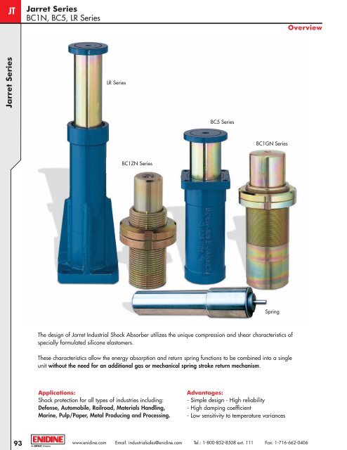
The design of <strong>Jarret</strong> Industrial Shock Absorber utilizes the unique compression and shear characteristics of<br />
specially formulated silicone elastomers.<br />
These characteristics allow the energy absorption and return spring functions to be combined into a single<br />
unit without the need for an additional gas or mechanical spring stroke return mechanism.<br />
Applications:<br />
Shock protection for all types of industries including:<br />
Defense, Automobile, Railroad, Materials Handling,<br />
Marine, Pulp/Paper, Metal Producing and Processing.<br />
Advantages:<br />
- Simple design - High reliability<br />
- High damping coefficient<br />
- Low sensitivity to temperature variances<br />
93<br />
www.enidine.com Email: industrialsales@enidine.com Tel.: 1-800-852-8508 ext. 111 Fax: 1-716-662-0406
<strong>Jarret</strong> <strong>Series</strong><br />
<strong>BC1N</strong>, <strong>BC5</strong>, <strong>LR</strong> <strong>Series</strong><br />
Visco-elastic Technology<br />
JT<br />
Impact Plate<br />
Sweeper<br />
Reservoir<br />
Visco- elastic<br />
Fluid<br />
Piston<br />
External Guide<br />
Visco-elastic Technology<br />
Mounting<br />
Flange<br />
Piston<br />
Retainer<br />
Visco-elastic technology makes use of the fundamental properties of specially formulated <strong>Jarret</strong> visco-elastic fluids.<br />
Compressibility:<br />
Preloaded spring function<br />
- F = F 0 + KX<br />
Viscosity:<br />
Shock absorber function<br />
- F = F 0 + KX + CV α with α<br />
between 0,1 and 0,4<br />
The two functions can be used separately or in combination, in the same product:<br />
Preloaded Spring:<br />
Spring Function Only<br />
• Hysteresis of between 5% and 10%<br />
• Reduced weight and space<br />
requirement<br />
• Force/stroke characteristic is<br />
independent of actuation speed<br />
Preloaded Spring Shock Absorbers:<br />
Combine Spring and Shock Absorber Functions<br />
• Dissipate between 30% and 100% of energy<br />
• Force/stroke characteristics remain relatively unchanged<br />
between 15°F and 160°F (-10°C and + 70°C)<br />
Shock Absorber Without Spring Return:<br />
Shock Absorbing Function Only<br />
• Dampening devices<br />
• Blocking Devices<br />
www.enidine.com Email: industrialsales@enidine.com Tel.: 1-800-852-8508 ext. 111 Fax: 1-716-662-0406<br />
94
JT<br />
<strong>Jarret</strong> Shock Absorbers<br />
<strong>BC1N</strong> <strong>Series</strong><br />
BC1ZN ➞ BC1GN <strong>Series</strong><br />
Technical Data<br />
<strong>BC1N</strong> <strong>Series</strong><br />
D5<br />
D6<br />
4 Holes D7<br />
L4<br />
L2<br />
L1<br />
L6<br />
Stroke<br />
D1<br />
D3<br />
L2<br />
L1<br />
L3<br />
Stroke<br />
D1<br />
D4<br />
Rear flange mounting - Fa<br />
Threaded body mounting - Fc<br />
L5<br />
Max<br />
Energy<br />
Return Force<br />
Capacity Stroke Extension Compression Rdy0<br />
Catalog No./ in-lbs. in. lbs. lbs. lbs.<br />
Model (kJ) (mm) (kN) (kN) (kN)<br />
BC1ZN<br />
BC1BN<br />
BC1DN<br />
BC1EN<br />
BC1FN<br />
BC1GN<br />
Rdymax<br />
Max. Reaction<br />
Force<br />
lbs.<br />
(kN)<br />
885 0.47 211.3 1,213.97 1349 2473<br />
(0,1) (12) (0,94) (5,4) (6) (11)<br />
3806 0.87 562 3,147.32 3,147 6070<br />
(0,43) (22) (2,5) (14,0) (14) (27)<br />
13,276 1.4 1,169 6,474.5 6,295 13,489<br />
(1,5) (35) (5,2) (28,8) (28) (60)<br />
30,093 1.8 1,753.5 9,666.78 10,116 22,481<br />
(3,4) (45) (7,8) (43,0) (45) (100)<br />
61,955 2.4 3,057.4 17,220.36 20,233 33,721<br />
(7) (60) (13,6) (76,6) (90) (150)<br />
123,910 3.1 4,271.4 29,225.16 29,225 51,706<br />
(14) (80) (19,0) (130,0) (130) (230)<br />
Catalog No./ L1 L2 L3 L4 L5 L6 R1 D1 D2 D3 D4 D5 D6 D7 Mass<br />
Model in. in. in. in. in. in. in. in. in. in. in. in. in. in. lbs.<br />
(mm) (mm) (mm) (mm) (mm) (mm) (mm) (mm) (mm) (mm) (mm) (mm) (mm) (mm) (kg.)<br />
BC1ZN<br />
BC1BN<br />
BC1BN-M<br />
BC1DN-70<br />
BC1DN-85<br />
BC1DN-M<br />
BC1EN<br />
BC1FN<br />
BC1GN<br />
2.95 2.1 2.1 0.39 0.28 1.7 – 0.75 0.79 1.5 2.2 1.6 0.28 0.7<br />
M25 x 1,5<br />
(75) (53) (52) (10) (7) (43) – (19)<br />
(20) (38) (57) (41) (7) (0,3)<br />
4.7 3.9 3.8 0.47 0.31 3.4 – 1.0 1.3 2.0 3.1 2.4 0.35 1.5<br />
M35 x 1,5<br />
(120) (98) (96) (12) (8) (86) – (25)<br />
(32) (52) (80) (60) (9) (0,7)<br />
4.7 3.9 3.8 0.47 0.35 – – 1.0 1.3 2.3 – – – 1.8<br />
M40 x 1,5<br />
(120) (98) (96) (12) (9) - – (25)<br />
(32) (58) – – – (0,8)<br />
6.9 5.5 5.4 0.47 0.43 5.0 – 1.5 1.8 2.8 3.5 2.8 0.35 4.2<br />
M50 x 1,5<br />
(175) (140) (138) (12) (11) (128) – (38)<br />
(45) (70) (90) (70) (9) (1,9)<br />
6.9 5.5 5.4 0.47 0.43 5.0 – 1.5 1.8 2.8 4.2 3.3 0.43 4.4<br />
M50 x 1,5<br />
(175) (140) (138) (12) (11) (128) – (38)<br />
(45) (70) (106) (85) (11) (2)<br />
6.9 5.5 5.4 0.47 0.43 – – 1.5 1.8 2.8 – – – 4.4<br />
M60 x 2<br />
(175)) (140) (138) (12) (11) – – (38)<br />
(45) (70) – – – (2)<br />
8.4 6.6 6.2 0.39 0.51 6.2 R. 5.1 2.4 2.8 3.9 4.8 4.0 0.43 11<br />
M75 x 2<br />
(213) (168) (158) (10) (13) (158) (R.130) (60)<br />
(72) (98) (122) (100) (11) (5)<br />
10.6 8.3 5.1 0.47 0.63 5.1 R. 5.9 2.9 3.5 4.7 5.9 4.7 0.51 23.1<br />
M90 x 2<br />
(270) (210) (130) (12) (16) (130) (R.150) (74,5)<br />
(90) (120) (150) (120) (13) (10,5)<br />
13.3 10.1 5.7 0.55 0.75 5.7 R. 13.8 3.5 4.3 5.7 6.9 5.6 0.70 37.5<br />
M110 x 2<br />
(337) (257) (145) (14) (19) (145) (R.350) (90)<br />
(110) (145) (175) (143) (18) (17)<br />
95<br />
www.enidine.com Email: industrialsales@enidine.com Tel.: 1-800-852-8508 ext. 111 Fax: 1-716-662-0406
<strong>Jarret</strong> Shock Absorbers<br />
<strong>BC1N</strong> <strong>Series</strong><br />
BC1ZN ➞ BC1GN <strong>Series</strong><br />
1 - Selection Chart<br />
5 - Calculation of Effective Reaction Rdy e<br />
Application Worksheet<br />
JT<br />
Rdy Rdymax - Rdy0<br />
e = x Ce + Rdy0 (0,1V + 0,8)<br />
C<br />
6 - Application Example<br />
Given data: Effective mass = 15 t,<br />
Effective speed = 0,8 m/s<br />
Impact frequency: 25 impacts/hour<br />
<strong>BC1N</strong> <strong>Series</strong><br />
1: BC1FN Selected<br />
Based On<br />
Impact velocity : 2 m/s<br />
Operating temperature : - 20° to + 40°C<br />
Surface protection : Electrolytic zinc<br />
Dynamic performance diagram<br />
Rdy0<br />
Force kN<br />
Rdymax<br />
2: Energy dissipated per impact is: 4,8 kJ<br />
3: Allowable impact frequency < 20x7/4.8<br />
4: Required stroke is 49 mm<br />
4,8<br />
Ce = 60<br />
7 (0,03 x 0.8 + 0,24)<br />
+1,36 - 1,17<br />
5: With an Rdy e = [(150 - 90) x 49/60) + 90)] x (0,1 x<br />
0,8 + 0,8) = 122 kN<br />
Symbols:<br />
En = Energy Capacity<br />
C = Maximum Stroke<br />
Rdy = Dynamic Reaction<br />
2 - Energy Calculation<br />
E =<br />
1<br />
M e V 2 e<br />
2<br />
3 - Allowable Impact Frequency<br />
F < 20 x<br />
En<br />
E<br />
Impacts/hour<br />
4 - Effective Stroke Calculation<br />
Stroke mm<br />
Compare with standard mechanical characteristics:<br />
En = 7 kJ, C = 60mm, Rdy0 = 90 kN and<br />
Rdymax = 150 kN<br />
All performance characteristics can be modified.<br />
Please advise us of your specific requirements.<br />
Ce = C<br />
E<br />
+1,36 - 1,17<br />
En (0,03 V + 0,24)<br />
www.enidine.com Email: industrialsales@enidine.com Tel.: 1-800-852-8508 ext. 111 Fax: 1-716-662-0406<br />
96
JT<br />
<strong>Jarret</strong> Shock Absorbers<br />
<strong>BC5</strong> <strong>Series</strong><br />
<strong>BC5</strong>A ➞ <strong>BC5</strong>E <strong>Series</strong><br />
Technical Data<br />
<strong>BC5</strong> <strong>Series</strong><br />
Rear Flange Mount - Fa<br />
4 holes ø D5<br />
ø D2<br />
ø D1<br />
L4<br />
L5<br />
L2<br />
Stroke C<br />
L6<br />
ø D3<br />
ø D4<br />
ø D2<br />
L8<br />
L7<br />
L5 L4<br />
L3<br />
Front Flange Mount - Fc<br />
Max<br />
Energy<br />
Return Force<br />
Capacity Stroke Extension Compression Rdy0<br />
Catalog No./ in-lbs. in. lbs. lbs. lbs.<br />
Model (kJ) (mm) (kN) (kN) (kN)<br />
<strong>BC5</strong>A-105<br />
<strong>BC5</strong>B-130<br />
<strong>BC5</strong>C-140<br />
<strong>BC5</strong>D-160<br />
<strong>BC5</strong>E-180<br />
Rdymax<br />
Max. Reaction<br />
Force<br />
lbs.<br />
(kN)<br />
221,268 4.1 4,159 31,630 37,543 69,691<br />
(25) (105) (18,5) (140,7) (167) (310)<br />
442,537 5.1 7,419 49,683 58,450 112,405<br />
(50) (130) (33,0) (221) (260) (500)<br />
663,806 5.5 11,015 73,827 89,924 157,366<br />
(75) (140) (49,0) (328,4) (400) (700)<br />
885,075 6.3 13,376 85,427 105,660 184,343<br />
(100) (160) (59,5) (380,0) (470) (820)<br />
1,327,612 7.1 26,269 122,656 143,878 247,290<br />
(150) (180) (117,0) (546) (640) (1 100)<br />
Catalog No./ L1 L2 L3 L4 L5 L6 L7 L8 D1 D2 D3 D4 D5 Mass<br />
Model in. in. in. in. in. in. in. in. in. in. in. in. in. lbs.<br />
(mm) (mm) (mm) (mm) (mm) (mm) (mm) (mm) (mm) (mm) (mm) (mm) (mm) (kg)<br />
<strong>BC5</strong>A<br />
16.3 10.8 5.5 0.79 1.2 0.59 5.3 4.1 4.6 4.6 3.4 4.7 0.55 55<br />
(415) (275) (140) (20) (30) (15) (135) (105) (116) (116) (87) (120) (14) (25)<br />
<strong>BC5</strong>B<br />
19.7 12.8 6.9 1.2 0.8 0.59 6.1 4.9 5.6 6.1 4.6 5.5 0.59 82<br />
(500) (325) (175) (30) (20) (15) (155) (125) (142) (155) (117) (140) (15) (37)<br />
<strong>BC5</strong>C<br />
20.5 12.4 8.1 1.2 1.4 1.4 6.9 5.5 6.3 6.3 5.2 6.2 0.70 99<br />
(520) (315) (205) (30) (36) (35) (175) (140) (160) (160) (132) (158) (18) (45)<br />
<strong>BC5</strong>D<br />
23 13.8 9.3 1.4 1.6 1.6 8.5 6.7 7.1 7.1 6.0 7.3 0.87 161<br />
(585) (350) (235) (35) (40) (40) (215) (170) (180) (180) (153) (185) (22) (73)<br />
<strong>BC5</strong>E<br />
26.4 15.9 10.4 1.6 1.8 1.8 9.8 7.7 8.5 8.5 7.2 8.7 1.0 258<br />
(670) (405) (265) (40) (45) (45) (250) (195) (215) (215) (182) (220) (26) (117)<br />
Impact Speed: <strong>BC5</strong> <strong>Series</strong> shock absorbers are designed for impact velocities of up to 4 m/sec. Higher impact velocities require custom modification.<br />
97<br />
www.enidine.com Email: industrialsales@enidine.com Tel.: 1-800-852-8508 ext. 111 Fax: 1-716-662-0406
<strong>Jarret</strong> Shock Absorbers<br />
<strong>BC5</strong> <strong>Series</strong><br />
<strong>BC5</strong>A ➞ <strong>BC5</strong>E <strong>Series</strong><br />
Application Worksheet<br />
JT<br />
Based On<br />
Impact velocity : 2 m/s<br />
Operating temperature : - 20° to + 40°C<br />
Surface protection : Electrolytic zinc<br />
Dynamic performance diagram<br />
Rdy0<br />
Force kN<br />
Rdymax<br />
4 - Calculation of Effective Reaction Rdy e<br />
Rdy Rdymax - Rdy0<br />
e = x Ce + Rdy0 (0,1V + 0,8)<br />
C<br />
5 - Application Example<br />
Data: Two shock absorbers in series, Effective mass<br />
m =300 t, Impact speed v = 1,2 m/s (which is an impact<br />
of 0,6 m/s on each shock absorber), Impact frequency = 15<br />
impacts/hour, Maximum allowable structural load 1000 kN<br />
<strong>BC5</strong> <strong>Series</strong><br />
Symbols:<br />
En = Energy Capacity<br />
C = Maximum Stroke<br />
Rdy = Dynamic Reaction<br />
Stroke mm<br />
1 1<br />
1: E = ( mV<br />
2<br />
2 ) - Selection <strong>BC5</strong>-E<br />
2<br />
2: Maximum allowable impact frequency is 15 x<br />
21 impacts/hour. Therefore 15 impacts/hour<br />
is acceptable.<br />
3: Required stroke is 167 mm<br />
150<br />
108<br />
1 - Energy Calculation<br />
E =<br />
1<br />
M e V 2 e<br />
2<br />
2 - Allowable Impact Frequency<br />
F < 15 x<br />
En<br />
E<br />
Impacts/hour<br />
3 - Effective Stroke Calculation<br />
E<br />
Ce = C +1,36 - 1,17<br />
En (0,03 V + 0,24)<br />
Ce = 180 x<br />
108<br />
150 (0,03 x 0.6 + 0,24)<br />
+1,36 - 1,17 = 156 mm<br />
156<br />
4: Rdye = ( 1 100 - 640) x + 640 ( 0,1x 0,6 + 0,8)<br />
180<br />
= 893 kN < 1000 kN, maximum allowable impact frequency<br />
Compare with standard mechanical characteristics for each<br />
shock absorber:<br />
En = 150 kJ, C = 180 mm, Rdy0 = 640 kN and<br />
Rdy max = 1100 kN<br />
All performance characteristics can be modified.<br />
Please advise us of your specific requirements.<br />
www.enidine.com Email: industrialsales@enidine.com Tel.: 1-800-852-8508 ext. 111 Fax: 1-716-662-0406<br />
98
JT<br />
<strong>Jarret</strong> Shock Absorbers<br />
X<strong>LR</strong> <strong>Series</strong><br />
X<strong>LR</strong>6-150 ➞ X<strong>LR</strong>-800 <strong>Series</strong><br />
Technical Data<br />
L7<br />
L8<br />
<strong>LR</strong> <strong>Series</strong><br />
ø D1<br />
L2<br />
L1<br />
L4 L5<br />
Stroke<br />
L3<br />
ø D3<br />
ø D4<br />
L6<br />
4 holes ø D5<br />
X<strong>LR</strong> <strong>Series</strong> - Front Flange Mount- Fc<br />
Max<br />
Energy<br />
Return Force<br />
Capacity Stroke Extension Compression Rdy0<br />
Catalog No./ in-lbs. in. lbs. lbs. lbs.<br />
Model (kJ) (mm) (kN) (kN) (kN)<br />
X<strong>LR</strong>6-150<br />
53,104 5.9 652 4,609 5,620 11,240<br />
(6) (150) (2,9) (20,5) (25) (50)<br />
X<strong>LR</strong>12-150<br />
106,209 5.9 1,866 8,655 14,837 22,481<br />
(12) (150) (8,3) (38,5) (66) (100)<br />
X<strong>LR</strong>12-200<br />
106,209 7.9 1,259 6,744 9,442 17,535<br />
(12) (200) (5,6) (30,0) (42) (78)<br />
X<strong>LR</strong>25-200<br />
221,269 7.9 3,012 16,726 21,537 33,721<br />
(25) (200) (13,4) (74,4) (95) (150)<br />
X<strong>LR</strong>25-270<br />
221,269 10.6 2,495 11,555 14,837 25,179<br />
(25) (270) (11,1) (51,4) (66) (112)<br />
X<strong>LR</strong>50-275<br />
442,537 10.8 4,429 29,225 26,527 51,706<br />
(50) (275) (19,7) (130,0) (118) (230)<br />
X<strong>LR</strong>50-400<br />
442,537 15.7 2,900 18,839 16,861 33,721<br />
(50) (400) (12,9) (83,8) (75) (150)<br />
X<strong>LR</strong>100-400<br />
885,075 15.7 5,620 36,531 39,342 71,939<br />
(100) (400) (25,0) (162,5) (175) (320)<br />
X<strong>LR</strong>100-600<br />
885,075 23.6 2,608 29,765 19,109 51,706<br />
(100) (600) (11,6) (132,4) (85) (230)<br />
X<strong>LR</strong>150-800<br />
1,327,612 31.5 5,216 34,216 17,984 56,202<br />
(150) (800) (23,2) (152,2) (80) (250)<br />
Impact Speed: Types X<strong>LR</strong> and BC<strong>LR</strong> <strong>Series</strong> shock absorbers are designed for impact velocities of up to 2 m/sec.<br />
Higher impact velocities require custom modification.<br />
Rdymax<br />
Max<br />
Reaction Force<br />
lbs.<br />
(kN)<br />
Catalog No./ L1 L2 L3 L4 L5 L6 L7 L8 D1 D2 D3 D4 D5 Mass<br />
Model in. in. in. in. in. in. in. in. in. in. in. in. in. lbs.<br />
(mm) (mm) (mm) (mm) (mm) (mm) (mm) (mm) (mm) (mm) (mm) (mm) (mm) (kg.)<br />
X<strong>LR</strong>6-150<br />
16.1 9.1 7.0 0.75 0 0.39 3.5 2.8 2.0 3.5 1.5 2.0 0.35 9.3<br />
(410) (231) (179) (19) (0) (10) (90) (70) (50) (90) (38) (50) (9) (4,2)<br />
X<strong>LR</strong>12-150<br />
18.9 11.2 7.7 0.71 0.60 0.47 4.3 3.3 3.0 3.5 2.2 3.1 0.43 24.3<br />
(480) (285) (195) (18) (15) (12) (110) (85) (75) (90) (57) (80) (11) (11)<br />
X<strong>LR</strong>12-200<br />
20.9 11.2 9.6 0.71 0.60 0.47 4.3 3.3 3.0 3.5 2.2 3.1 0.43 24.3<br />
(530) (285) (245) (18) (15) (12) (110) (85) (75) (90) (57) (80) (11) (11)<br />
X<strong>LR</strong>25-200<br />
24.4 14.6 9.8 0.79 0.71 0.47 5.3 4.1 3.5 4.3 2.8 4.0 0.6 44.1<br />
(620) (370) (250) (20) (18) (12) (135) (105) (90) (110) (72) (100) (14) (20)<br />
X<strong>LR</strong>25-270<br />
27.2 14.6 12.6 0.79 0.71 0.47 5.3 4.1 3.5 4.3 2.8 4.0 0.6 55.1<br />
(690) (370) (320) (20) (180 (12) (135) (105) (90) (110) (72) (100) (14) (25)<br />
X<strong>LR</strong>50-275<br />
33.7 20.5 13.2 1.0 0.79 0.60 6.9 5.5 4.3 5.9 3.4 4.7 0.71 88.2<br />
(855) (520) (335) (25) (20) (15) (175) (140) (110) (150) (87) (120) (18) (40)<br />
X<strong>LR</strong>50-400<br />
38.6 20.5 18.1 1.0 0.79 0.60 6.9 5.5 4.3 5.9 3.4 4.7 0.71 88.2<br />
(980) (520) (460) (25) (20) (15) (175) (140) (110) (150) (87) (120) (18) (40)<br />
X<strong>LR</strong>100-400<br />
53.9 35.8 18.1 1.0 0.79 0.60 6.9 5.5 4.3 5.9 3.4 4.7 0.71 143.3<br />
(1370) (910) (460) (25) (20) (15) (175) (140) (110) (150) (87) (120) (18) (65)<br />
X<strong>LR</strong>100-600<br />
61.8 35.8 26.0 1.0 0.79 0.60 6.9 5.5 4.3 5.9 3.4 4.7 0.71 143.3<br />
(1570) (910) (660) (25) (20) (15) (175) (140) (110) (150) (87) (120) (18) (65)<br />
X<strong>LR</strong>150-800<br />
103.9 70.1 33.9 1.0 0.79 0.60 6.9 5.5 4.3 5.9 3.4 4.7 0.71 253.5<br />
(2640) (1780) (860) (25) (20) (15) (175) (140) (110) (150) (87) (120) (18) (115)<br />
Rear Flange Mounting - Fa on Request.<br />
99<br />
www.enidine.com Email: industrialsales@enidine.com Tel.: 1-800-852-8508 ext. 111 Fax: 1-716-662-0406
<strong>Jarret</strong> Shock Absorbers<br />
X<strong>LR</strong> <strong>Series</strong><br />
X<strong>LR</strong>6-150 ➞ X<strong>LR</strong>-800 <strong>Series</strong><br />
Based On<br />
Impact velocity : 2 m/s<br />
Operating temperature : - 20° to + 40°C<br />
Surface protection : Electrolytic zinc & Painting<br />
Dynamic performance diagram<br />
Rdy0<br />
Force kN<br />
Rdymax<br />
4 - Calculation of Effective Reaction Rdy e<br />
Application Worksheet<br />
Rdy Rdymax - Rdy0<br />
e = x Ce + Rdy0 (0,1V + 0,8)<br />
C<br />
5 - Application Example<br />
Data: Effective mass = 30 t<br />
Effective impact speed = 2,2 m/s<br />
Maximum allowable structural force: 350 kN<br />
1: BC<strong>LR</strong>400 selected<br />
JT<br />
<strong>LR</strong> <strong>Series</strong><br />
Symbols:<br />
En = Energy Capacity<br />
C = Maximum Stroke<br />
Rdy = Dynamic Reaction<br />
1 - Energy Calculation<br />
1<br />
E = M e V 2<br />
2 e<br />
2 - Allowable Impact Frequency<br />
Stroke mm<br />
2: Energy dissipated/impact is 72,6 kJ<br />
3: Maximum allowable impact frequency<br />
8 x 100 / 72,6 = 11 (10
JT<br />
<strong>Jarret</strong> Shock Absorbers<br />
BC<strong>LR</strong> <strong>Series</strong><br />
BC<strong>LR</strong>-100 ➞ BC<strong>LR</strong>-1000 <strong>Series</strong><br />
Technical Data<br />
L7<br />
L8<br />
<strong>LR</strong> <strong>Series</strong><br />
ø D1<br />
4 holes ø D5<br />
L2<br />
L4 L5 Stroke<br />
L3<br />
L1<br />
ø D3<br />
ø D4<br />
L6<br />
BC<strong>LR</strong> <strong>Series</strong> - Front Flange Mount - Fc<br />
Max<br />
Energy<br />
Return Force<br />
Capacity Stroke Extension Compression Rdy0<br />
Catalog No./ in-lbs. in. lbs. lbs. lbs.<br />
Model (kJ) (mm) (kN) (kN) (kN)<br />
BC<strong>LR</strong>-100<br />
885,075 15.7 6,744 36,403 42,714 69,691<br />
(100) (400) (30,0) (161,9) (190) (310)<br />
BC<strong>LR</strong>-150<br />
1,327,612 19.7 9,330 47,300 44,962 85,427<br />
(150) (500) (41,5) (201,4) (200) (380)<br />
BC<strong>LR</strong>-220S<br />
1,947,614 15.7 10,105 60,698 85,427 153,944<br />
(220) (400) (45,0) (270,0) (380) (685)<br />
BC<strong>LR</strong>-250<br />
2,212,686 25.6 10,116 56,877 60,698 110,156<br />
(250) (650) (45,0) (253,0) (270) (490)<br />
BC<strong>LR</strong>-400<br />
3,540,298 33.5 11,144 69,214 74,187 134,885<br />
(400) (850) (49,6) (307,9) (330) (600)<br />
BC<strong>LR</strong>-600<br />
5,310,477 41.3 10,678 79,020 83,179 166,359<br />
(600) (1050) (47,5) (351,5) (370) (740)<br />
BC<strong>LR</strong>-800<br />
7,080,597 47.2 14,433 99,141 96,668 193,336<br />
(800) (1200) (64,2) (441,0) (430) (860)<br />
BC<strong>LR</strong>-1000<br />
8,850,746 51.2 19,109 120,048 112,405 224,809<br />
(1000) (1300) (85,0) (534,0) (500) (1000)<br />
Impact Speed: Types X<strong>LR</strong> and BC<strong>LR</strong> <strong>Series</strong> shock absorbers are designed for impact velocities of up to 2 m/sec.<br />
Higher impact velocities require custom modification.<br />
Rdymax<br />
Max<br />
Reaction Force<br />
lbs.<br />
(kN)<br />
Catalog No./ L1 L2 L3 L4 L5 L6 L7 L8 D1 D2 D3 D4 D5 Mass<br />
Model in. in. in. in. in. in. in. in. in. in. in. in. in. lbs.<br />
(mm) (mm) (mm) (mm) (mm) (mm) (mm) (mm) (mm) (mm) (mm) (mm) (mm) (kg.)<br />
BC<strong>LR</strong>-100<br />
44.1<br />
(1120)<br />
26.0<br />
(660)<br />
18.1<br />
(460)<br />
1.0<br />
(25)<br />
0.79<br />
(20)<br />
0.60<br />
(15)<br />
6.9<br />
(175)<br />
5.5<br />
(140)<br />
5.1<br />
(130)<br />
5.9<br />
(150)<br />
4.3<br />
(110)<br />
5.5<br />
(140)<br />
0.71<br />
(18)<br />
139.0<br />
(63)<br />
BC<strong>LR</strong>-150<br />
53.1 30.5 22.6 1.2 1.0 0.79 8.5 6.7 5.5 7.3 4.7 5.9 0.87 198.4<br />
(1350) (775) (575) (30) (25) (20) (215) (170) (140) (185) (120) (150) (22) (90)<br />
BC<strong>LR</strong>-220S<br />
49.5 30.8 18.7 1.2 1.0 0.79 8.5 6.7 5.5 7.3 4.7 5.9 0.87 220.5<br />
(1258) (783)) (475) (30) (25) (20) (215) (170) (140) (185) (120) (150) (22) (100)<br />
BC<strong>LR</strong>-250<br />
68.9 40.4 28.5 1.2 1.0 0.79 8.5 6.7 6.1 7.3 6.9 6.7 0.87 297.6<br />
(1750) (1025) (725) (30) (25) (20) (215) (170) (155) (185) (135) (170) (22) (135)<br />
BC<strong>LR</strong>-400<br />
86.0 49.2 36.8 1.4 1.0 1.0 10.4 8.3 6.9 9.3 5.9 7.5 1.1 480.6<br />
(2185) (1250) (935) (35) (25) (25) (265) (210) (175) (235) (150) (190) (27) (218)<br />
BC<strong>LR</strong>-600<br />
100.6 55.9 44.7 1.4 1.0 1.0 10.4 8.3 7.9 9.3 6.9 8.5 1.1 650.4<br />
(2555) (1420) (1135) (35) (25) (25) (265) (210) (200) (235) (175) (215) (27) (295)<br />
BC<strong>LR</strong>-800<br />
115.6 64.2 51.4 1.6 1.4 1.2 11.8 9.4 8.7 10.6 7.5 9.3 1.2 926<br />
(2935) (1630) (1305) (40) (35) (30) (300) (240) (220) (270) (190) (235) (30) (420)<br />
BC<strong>LR</strong>-1000<br />
127.0 71.7 55.3 1.6 1.4 1.2 11.8 9.4 9.1 10.6 8.1 9.8 1.2 1036.2<br />
(3225) (1820) (1405) (40) (35) (30) (300) (240) (230) (270) (205) (248) (30) (470)<br />
Rear Flange Mounting - Fa on Request.<br />
101<br />
www.enidine.com Email: industrialsales@enidine.com Tel.: 1-800-852-8508 ext. 111 Fax: 1-716-662-0406
<strong>Jarret</strong> Shock Absorbers<br />
BC<strong>LR</strong> <strong>Series</strong><br />
BC<strong>LR</strong>-100 ➞ BC<strong>LR</strong>-1000 <strong>Series</strong><br />
Based On<br />
Impact velocity : 2 m/s<br />
Operating temperature : - 20° to + 40°C<br />
Surface protection : Electrolytic zinc & Painting<br />
Dynamic performance diagram<br />
Rdy0<br />
Force kN<br />
Rdymax<br />
4 - Calculation of Effective Reaction Rdy e<br />
Application Worksheet<br />
Rdy Rdymax - Rdy0<br />
e = x Ce + Rdy0 (0,1V + 0,8)<br />
C<br />
5 - Application Example<br />
Data: Effective mass = 75 t<br />
Effective impact speed = 2,7 m/s<br />
Maximum allowable structural force: 650 kN<br />
1: BC<strong>LR</strong>400 selected<br />
JT<br />
<strong>LR</strong> <strong>Series</strong><br />
Symbols:<br />
En = Energy Capacity<br />
C = Maximum Stroke<br />
Rdy = Dynamic Reaction<br />
1 - Energy Calculation<br />
1<br />
E = M e V 2<br />
2 e<br />
2 - Allowable Impact Frequency<br />
Stroke mm<br />
2: Energy dissipated/impact is 274 kJ<br />
3: Maximum allowable impact frequency<br />
8 x 400 / 274 = 12 (10 impacts/hour is acceptable)<br />
4: Effective stroke:<br />
274<br />
Ce = 850 x + 1,83- 1,35<br />
400 (0,027 x 2.7 + 0,22)<br />
Ce = 587mm<br />
F < 8 x<br />
En<br />
E<br />
Impacts/hour<br />
5: Rdye = 520 (0,1 x 2,7 + 0,8) = 556 kN<br />
3 - Required Stroke Calculation<br />
Ce = C E +1,83 - 1,35<br />
En (0,027 V + 0,22)<br />
(which is less than maximum allowable reaction force of 650 kN)<br />
Compare with Standard<br />
Performance characteristics are:<br />
En = 400 kJ, C = 850 mm,<br />
Rdymax = 600 kN<br />
Rdy0 = 330 kN<br />
All performance characteristics can be modified.<br />
Please advise us of your specific requirements.<br />
www.enidine.com Email: industrialsales@enidine.com Tel.: 1-800-852-8508 ext. 111 Fax: 1-716-662-0406<br />
102