Linkbelt-LS208H2-Spec - Rawalwasia
Linkbelt-LS208H2-Spec - Rawalwasia
Linkbelt-LS208H2-Spec - Rawalwasia

Create successful ePaper yourself
Turn your PDF publications into a flip-book with our unique Google optimized e-Paper software.
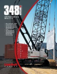
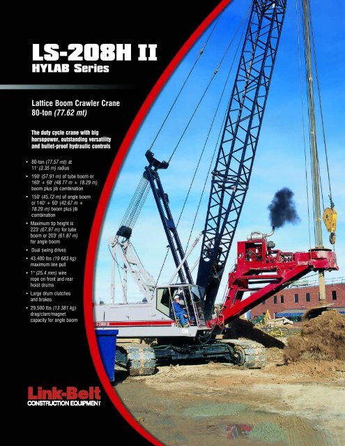
LS-208H II<br />
HYLAB Series<br />
Lattice Boom Crawler Crane<br />
80-ton (77.62 mt)<br />
The duty cycle crane with big<br />
horsepower, outstanding versatility<br />
and bullet-proof hydraulic controls<br />
• 80-ton (77.57 mt) at<br />
11' (3.35 m) radius<br />
• 190' (57.91 m) of tube boom or<br />
160' + 60' (48.77 m + 18.29 m)<br />
boom plus jib combination<br />
• 150' (45.72 m) of angle boom<br />
or 140' + 60' (42.67 m +<br />
18.29 m) boom plus jib<br />
combination<br />
• Maximum tip height is<br />
223' (67.97 m) for tube<br />
boom or 203' (61.87 m)<br />
for angle boom<br />
• Dual swing drives<br />
• 43,400 lbs (19 683 kg)<br />
maximum line pull<br />
• 1" (25.4 mm) wire<br />
rope on front and rear<br />
hoist drums<br />
• Large drum clutches<br />
and brakes<br />
• 29,500 lbs (13 381 kg)<br />
drag/clam/magnet<br />
capacity for angle boom
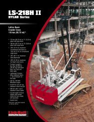
LS-208H II<br />
HYLAB Series<br />
A robust performer in Link-Belt’s renowned HYLAB (hydraulic lattice boom)<br />
family, the LS-208H II is built for ultimate versatility on the job site.<br />
Duty cycle requirements<br />
The LS-208H II is the<br />
machine for the job<br />
• The tube boom is ideally suited for lift<br />
crane work and combination lift/duty<br />
cycle requirements. The angle boom is a<br />
top notch performer in dragline,<br />
clamshell, pile driving and other severe<br />
duty cycle applications.<br />
• Outfitting the angle boom with the<br />
optional live mast makes for fast<br />
assembly and disassembly.<br />
• The LS-208H II can operate in automatic<br />
brake mode or with true gravity freefall<br />
operation.<br />
• The boom top section features standard<br />
pin-on points for attachment of the jib, a<br />
5' (1.52 m) tip extension or a universal<br />
pile driving lead adapter.<br />
• 5' (1.52 m) auxiliary tip extension is<br />
available to improve clearance between<br />
the working hoist lines (9-ton (8.16 mt)<br />
capacity).<br />
• Head machinery options include<br />
wide mouth drag sheaves or<br />
lift/clam sheaves.<br />
• Pile driving lead adapter available<br />
Optional third drum<br />
with free spooling<br />
Big horsepower for<br />
80-ton class crane<br />
• 263 horsepower (196 kW)<br />
• High horsepower for 80-ton class<br />
crane allows for high line speeds<br />
under high line pull conditions such as<br />
production duty cycle work including<br />
drag line/clamshell/dock/scrap and<br />
foundation demands.<br />
• Extra capacity cooling beyond normal lift<br />
crane requirements to satisfy the higher<br />
horsepower and hydraulic flows the<br />
LS-208H II provides.<br />
Dual swing drives<br />
• Dual swing motors and drive boxes<br />
on the LS-208H II ensure long swing<br />
life under the harshest demands.<br />
What you’ve come to<br />
expect from a Link-Belt<br />
• “Fine Inching” control for super<br />
precise handling<br />
• Compact travel drives, hydraulic selfadjusting<br />
tracks and sealed idler and<br />
drive planetaries<br />
• High travel torque<br />
Service after the sale<br />
When you invest in a Link-Belt crane,<br />
you also invest in a 125-year legacy<br />
of outstanding customer support.<br />
Link-Belt’s customer service helps<br />
you maintain your investment over<br />
the long term, with the industry’s<br />
most comprehensive crane product<br />
support available.<br />
Link-Belt crawler crane<br />
owners praise HYLAB’s<br />
low operating cost ...<br />
the best in its class.<br />
Crane operations<br />
control center<br />
• Armchair mounted, pilot-operated<br />
hydraulic controls<br />
• An ergonomically designed to<br />
provide maximum comfort,<br />
control and load visibility<br />
Outstanding transportability<br />
• The modular design of the<br />
LS-208H II transports in only<br />
three loads.<br />
• Link-Belt’s optional Quick Draw<br />
feature simplifies self-assembly,<br />
disassembly and load-out.<br />
Hydraulic cylinders in the boom<br />
base section pick up and handle<br />
the boom<br />
sections and counterweights.<br />
• On the LS-208H II, you can remove<br />
counterweights, break down the<br />
boom, retract the sideframes, store<br />
the catwalks, pin the live mast and<br />
gantry, and be ready to load out in<br />
2-3 hours.<br />
Link-Belt Construction Equipment Company Lexington, Kentucky www.linkbelt.com<br />
® Link-Belt is a registered trademark. Copyright 2000. All rights reserved. We are constantly improving our products and therefore reserve the right to change designs and specifications.<br />
Litho in USA 9/00 #4246
5436---0205---H8<br />
1<br />
Technical Data<br />
<strong>Spec</strong>ifications & Tube Boom Capacities<br />
LS -208H II<br />
Crawler Crane<br />
80 Ton (72.57 metric ton)<br />
CAUTION: This material is supplied for reference use<br />
only. Operator must refer to in---cab Crane Rating<br />
Manual and Operator’s Manual to determine<br />
allowable crane lifting capacities and assembly and<br />
operating procedures.<br />
Link-Belt Cranes<br />
LS---208HII
5436---0205---H8<br />
LS---208HII<br />
Link-Belt Cranes
5436---0205---H8<br />
1<br />
Table Of Contents<br />
Pages<br />
<strong>Spec</strong>ifications 1--8<br />
Tube Boom Capacities 1--12<br />
Tube Boom + Jib Capacities 1--16<br />
Link-Belt Cranes<br />
LS---208HII
5436---0205---H8<br />
This page intentionally left blank<br />
LS---208HII<br />
Link-Belt Cranes
<strong>Spec</strong>ifications<br />
Lattice Boom Crawler Crane<br />
LS–208H II 80–ton (72.57 metric ton)<br />
HYLAB Series<br />
<br />
<br />
<br />
<br />
<br />
<br />
<br />
<br />
<br />
<br />
<br />
<br />
<br />
<br />
<br />
<br />
<br />
<br />
<br />
<br />
<br />
<br />
<br />
<br />
LS–208H II
LS–208H II Machine Transport Weights – approximate<br />
<br />
<br />
<br />
<br />
<br />
<br />
<br />
<br />
<br />
<br />
<br />
<br />
<br />
<br />
<br />
<br />
<br />
<br />
<br />
<br />
<br />
<br />
<br />
<br />
<br />
<br />
<br />
<br />
<br />
<br />
<br />
<br />
<br />
<br />
<br />
<br />
<br />
<br />
<br />
<br />
<br />
<br />
<br />
<br />
<br />
<br />
<br />
<br />
<br />
<br />
<br />
<br />
<br />
<br />
<br />
<br />
<br />
<br />
<br />
<br />
<br />
<br />
<br />
<br />
<br />
<br />
<br />
<br />
<br />
<br />
<br />
<br />
<br />
<br />
<br />
<br />
<br />
<br />
LS–208H II
LS–208H II Transportation Weights – approximate<br />
Base Machine: Rigid Boom Backstops, 27 Gallons (102.2L) of Fuel, Catwalks (front and right side), 24’ (7.3m) Live Mast, Bridle & Spreader Bar, 14–Part<br />
Boom Hoist Reeving, 610’ (186 m) of Type ‘DB’ Front Hoist Rope, 540’ (165m) of Type ‘RB’ Rear Hoist Rope and Auxiliary Lifting Bail.<br />
Gross Weight<br />
Item Description<br />
Load<br />
lb. kg.<br />
#1<br />
Base Machine 92,094 41 773 1<br />
Transport Loads<br />
Load<br />
#2<br />
Load<br />
#3<br />
Notes and Load Summary<br />
Add “A” Counterweight 19,600 8 890 1 Numbers in the load columns to<br />
the left represent quantities.<br />
Add “B” Counterweight 20,100 9 117 1<br />
Add Hydraulic Third Drum w/o rope 1,345 610 Estimated transport load<br />
Add 20’ (6.1m) Tube Base Section 1,790 812<br />
assumes the load out consist of<br />
Add 20’ (6.1m) Tube Top Section 2,700 1 225<br />
150’ (45.7m) of angle boom +<br />
60’ (18.3m) of jib with full<br />
Add 10’ (3.05m) Tubular Extension w/pins & pendants 677 307<br />
counterweight.<br />
Add 20’ (6.1m) Tubular Extension w/pins & pendants 1076 488<br />
Add 30’ (9.1m) Tubular Extension w/pins & pendants 1,481 672 Support loads were targeted at<br />
Add 20’ (6.1m) Angle Base Section 2,853 1 294 1<br />
45,000 lb (20 412kg), 8’–6”<br />
(2.6m) wide, 48’ (14.6m) long,<br />
Add 20’ (6.1m) Angle Top Section with 4 Lifting Sheaves 3,195 1 449 1<br />
and 13’–6” (4.1m) high using a<br />
Add 20’ (6.1m) Angle Top Section with 3 Lifting Sheaves 3,642 1 652<br />
drop deck trailer. This may vary<br />
Add 20’ (6.1m) Angle Top Section with 2 Lifting Sheaves 3,475 1 576<br />
depending on state laws, empty<br />
truck/trailer weights, and style<br />
Add 10’ (3.05m) Angular Extension w/pins & pendants 992 450 1<br />
of trailer.<br />
Add 20’ (6.1m) Angular Extension w/pins & pendants 1,625 737 2<br />
Add 30’ (9.1m) Angular Extension w/pins & pendants 2,264 1 027 2 Estimated weights vary by<br />
Add Bridle & Spreader Bar Only (No Live Mast) 756 343<br />
+/– 2%.<br />
Add Tagline Winder 650 295<br />
Estimated Total Load of #1<br />
Add Fairleader 500 227<br />
92,094 lbs. (41 773kg).<br />
Add PAT DS–350 100 45<br />
Estimated Total Load of #2<br />
Add 30’ (9.1m) Tubular Jib 1,683 763 1<br />
29,641 lbs. (13 445kg).<br />
Add 15’ (4.6m) Tubular Jib Extension 317 144 2<br />
Add 5’ (1.5m) Auxiliary Tip Extension 730 331 Estimated Total Load of #3<br />
Add Holding Rope – 1” X 190’ Type ‘DB’ 334 152<br />
29,504 lbs (13 383kg).<br />
Add Closing Rope – 1” X 240’ Type ‘DB’ 422 192<br />
Add Inhaul Rope – 1” X 105’ Type ‘M’ 185 84<br />
Add Jib Wire Rope – 1” X 700’ Type ‘DB’ 1,295 587<br />
Add 3rd Drum Wire Rope 0.63” X 385’ Type ‘ZB’ 312 141<br />
Add 3rd Drum Wire Rope 0.63” X 385’ Type ‘WB’ 296 134<br />
Add Auxiliary Lifting Bail 191 87<br />
Add 15–ton (13.6mt) Hook Ball – Non Swivel 750 340 1<br />
Add 15–ton (13.6mt) Hook Ball – Swivel 760 345<br />
Add 80–ton (72.6mt) 4 Sheave Hook Block 1,560 708 1<br />
Remove Front Hoist Rope 1” X 610’ Type ‘DB’ –1,147 –520<br />
Remove Jib Wire Rope 1” X 540’ Type ‘RB’ –1,080 –490<br />
Remove 24’ (7.3m) Live Mast with Bridle & Spreader Bar –2,356 –1 069<br />
Add 50 gallons (189.3L) of Fuel 362 164<br />
Machine Working Weight<br />
Option Description Gross<br />
Weight<br />
lbs. (kg)<br />
1 Base Machine equipped with 40’ (12.2m) of tubular boom, live mast, “A” counterweight, 610’ (186m) front hoist<br />
rope, 540’ (164.6m) rear hoist rope, 80–ton (72.6mt) hook block, 77 gallons (291.4L) of fuel, and<br />
200 lbs. (90.7kg) operator.<br />
2 Option #1 plus “B” counterweight, midpoint pendants, and 150’ (45.7m) of boom extensions to obtain 190’<br />
(57.91m) of main boom.<br />
3 Option #2 plus 60’ (18.3m) of jib and 15–ton (13.6mt) hookball – subtract 20’ (6.1m) of boom extension and<br />
midpoint pendants to obtain maximum 170’ + 60’ (51.82 + 18.29m) of main boom + jib.<br />
4 Base Machine equipped with 40’ (12.2m) of angle boom, live mast, “A” counterweight, 610’ (186m) front hoist<br />
rope, 540’ (165m) rear hoist rope, 80–ton (72.6mt) hook block, 77 gallons (291.4L) of fuel, and<br />
200 lbs. (90.7kg) operator.<br />
117,291<br />
(53 202)<br />
145,355<br />
(65 932)<br />
147,060<br />
(66 705)<br />
118,849<br />
(53 909)<br />
5 Option #4 plus “B” counterweight and 110’ (33.5m) of boom extensions to obtain 150’ (45.7m) of main boom. 147,719<br />
(67 004)<br />
6 Option #5 plus 60’ (18.3m) of jib and 15–ton (13.6mt) hookball to obtain maximum 150’ + 60’ (45.7 +<br />
18.3m) of main boom + jib.<br />
Notes:<br />
1. Ground bearing pressure is based on the total weight distributed evenly over the track contact area.<br />
2. Total contact area for 36” (0.91m) track shoes is 15,689 in 2 (101,219cm 2 ).<br />
150,787<br />
(68 396)<br />
Ground Bearing<br />
Pressure<br />
psi (kg/cm 2 )<br />
7.48<br />
(0.52)<br />
9.26<br />
(0.65)<br />
9.37<br />
(0.66)<br />
7.58<br />
(0.53)<br />
9.42<br />
(0.66)<br />
9.61<br />
(0.67)<br />
–3–<br />
LS–208H II
Attachment<br />
Options<br />
40’ – 190’ (12.2 –<br />
57.9m) Tube Boom<br />
Basic Tube Boom – 40’ (12.2m) two–<br />
piece design that utilizes a 20’ (6.1m)<br />
base section and a 20’ (6.1m) open throat<br />
top section with in–line connecting pins<br />
on 54” (1.4m) wide and 44” (1.1m) deep<br />
centers.<br />
Boom feet on 50” (1.3m) centers<br />
3” (76.2mm) diameter chords<br />
Lugs on base section to attach carrying<br />
links<br />
Skywalk platform<br />
Deflector roller on top section<br />
Permanent skid pads mounted on top<br />
section to protect head machinery<br />
Rigid sheave guards<br />
Five 18” (0.5m) root diameter steel<br />
sheaves mounted on sealed anti–friction<br />
bearings<br />
Mechanical boom angle indicator<br />
<br />
<br />
<br />
<br />
<br />
<br />
<br />
<br />
<br />
<br />
<br />
Tube Boom<br />
Extensions<br />
Suggested Quantity for<br />
Max. Boom<br />
10’ (3.05m) 1<br />
20’ (6.10m) 1<br />
30’ (9.14m) 4<br />
Deflector roller on top of each section<br />
Appropriate length pendants<br />
Maximum tube boom tip height of 193’<br />
(58.8m)<br />
40’ – 150’ (12.2 –<br />
45.7m) Angle Boom<br />
Basic Angle Boom – 40’ (12.2m) two–<br />
piece design that utilizes a 20’ (6.1m)<br />
base section and a 20’ (6.1m) open throat<br />
top section with in–line connecting pins.<br />
Boom extensions are 48” (1.2m) wide and<br />
48” (1.2m) deep at outside dimensions of<br />
angles.<br />
Boom feet on 50” (1.3m) centers<br />
4” X 4” X 0.38” (101.6 x 101.6x 9.5mm)<br />
angle chords<br />
Lugs on base section to attach carrying<br />
links<br />
Skywalk platform<br />
Deflector roller on top section<br />
Permanent skid pads mounted on top<br />
section to protect head machinery<br />
Rigid sheave guards<br />
Four 18” (0.5m) root diameter steel<br />
sheaves mounted on sealed anti–<br />
friction bearings<br />
Mechanical boom angle indicator<br />
<br />
<br />
<br />
<br />
<br />
<br />
Angle Boom<br />
Extensions<br />
Suggested Quantity for<br />
Max. Boom<br />
10’ (3.05m) 1<br />
20’ (6.10m) 2<br />
30’ (9.14m) 2<br />
Deflector roller on top of each section<br />
Appropriate length pendants<br />
Maximum angle boom tip height of 154’<br />
(46.9m)<br />
<br />
30’ – 60’ (9.1– 18.3m)<br />
Tube Jib<br />
Basic Tube Jib – 30’ (9.14m) two–piece<br />
design that utilizes a 15’ (4.6m) base section<br />
and a 15’ (4.6m) top section with in–<br />
line connecting pins on 32” (0.8m) wide<br />
and 24” (0.6m) deep centers.<br />
2” (50.8mm) diameter tubular chords<br />
One 18.5” (0.46m) root diameter steel<br />
sheave mounted on sealed anti–friction<br />
bearings.<br />
15’ (4.6m) jib extensions provide jib<br />
lengths at 45’ (13.76m) and 60’ (18.3m)<br />
Jib offset angles at 5, 15 and 25<br />
degrees<br />
Maximum tip height of boom + jib is 233’<br />
(71.02m) using the tube boom and 214’<br />
(65.23m) using the angle boom<br />
<br />
Auxiliary 5’ (1.5m)<br />
Tip Extension<br />
Designed to use instead of a jib to provide<br />
clearance between working hoist lines.<br />
The extension is equipped with a single<br />
15.25” (0.4m) root diameter steel sheave<br />
mounted on sealed anti–friction bearings.<br />
Maximum capacity is 9–ton (8.2mt).<br />
<br />
Boom Hoist System<br />
Designed to lift off maximum boom or<br />
maximum boom plus jib unassisted.<br />
Operates up to a maximum boom angle of<br />
82 degrees. Automatically limits maximum<br />
boom angle operation.<br />
Retractable gantry frame<br />
Pin–on bail frame<br />
14–part reeving with 5/8” (14.7mm)<br />
type ‘AC’ wire rope<br />
Bridle assembly<br />
24’ (7.3m) live mast (optional for angle<br />
attachment)<br />
Two 1.25” (31.8mm) pendants<br />
Tubular boom backstops (rigid type)<br />
Sheaves contain sealed anti–friction<br />
bearings<br />
Boom speed from 10–70 is 52 seconds<br />
with no load and 94 seconds with<br />
full load. Speed was determined using<br />
100’ (30.5m) of tube boom<br />
LS–208H II
Revolving<br />
Upperstructure<br />
<br />
Frame<br />
All welded steel frame with precision machined<br />
surfaces for mating parts.<br />
<br />
Engine<br />
Mitsubishi 6D24–TEB with oil cooler, air cleaner,<br />
fuel filter, water separator, hour meter, tachometer,<br />
and electrical shutdown.<br />
Number of cylinders 6<br />
Bore and stroke – in<br />
(mm)<br />
Piston displacement – in 3<br />
(cm 3 )<br />
5.12 x 5.91<br />
(130 x 150)<br />
729<br />
(11945)<br />
Engine rpm at full load speed 2,000<br />
Hi–idle rpm 2,200<br />
Full load speed – horsepower<br />
(kw)<br />
263 (196)<br />
Peak torque – ft lb (joule) 746 (1011)<br />
Peak torque – rpm 1,400<br />
Electrical system<br />
Batteries<br />
<br />
24 volt<br />
2–12 volt<br />
Hydraulic System<br />
<strong>Spec</strong>ifications<br />
Hydraulic Pumps – The pump arrangement<br />
is designed to provide hydraulically<br />
powered functions allowing positive, precise<br />
control with independent or simultaneous<br />
operation of all crane functions.<br />
Two variable displacement pumps operating<br />
at 4,000 psi (281kg/cm 2 ) and 64<br />
gal/min (243L/min) powers load hoist<br />
drums, boom hoist drum, optional third<br />
drum, and travel.<br />
One fixed displacement gear type pump<br />
operating at 3,600 psi (250kg/cm 2 ) and<br />
31 gal/min (117L/min) powers the swing<br />
and treadmember retract cylinders.<br />
One fixed diplacement gear type pump<br />
operating at 3,000 psi (210kg/cm 2 ) and<br />
35 gal/min (130L/min) powers the<br />
swing motor.<br />
One fixed displacement gear type<br />
pump operating at 1,200 psi (84.4kg/<br />
cm 2 ) and 10.5 gal/min (39.7L/min) powers<br />
the pilot control system, clutches,<br />
brakes and pump controls.<br />
<br />
<br />
<br />
<br />
<br />
<br />
<br />
<br />
<br />
<br />
<br />
<br />
<br />
<br />
<br />
<br />
<br />
Load Hoist Drums<br />
Each drum contains a pilot controlled, bi–<br />
directional, axial piston motor and a planetary<br />
gear reduction unit to provide positive<br />
control under all load conditions.<br />
Power up/down & free–fall operation<br />
modes<br />
Automatic brake mode (spring applied,<br />
hydraulically released, band type<br />
brake)<br />
1” (25.4mm) grooved lagging<br />
Drum pawl controlled manually<br />
Electronic drum rotation indicators<br />
Mounted on anti–friction bearings<br />
18.70” (0.47m) root diameter<br />
33.86” (0.86m) flange diameter<br />
20.47” (0.52m) width<br />
<br />
<br />
<br />
<br />
<br />
<br />
<br />
<br />
<br />
<br />
<br />
<br />
<br />
Optional Front<br />
Mounted Third Hoist<br />
Drum<br />
The hydraulic winch is pinned to the front<br />
of the upper frame and is used in conjunction<br />
with a fleeting sheave and 3–sheave<br />
idler assembly to run the wire rope over<br />
the boom top section.<br />
Free–spooling capability for pile<br />
driving applications<br />
10.63” (0.27m) root diameter<br />
20” (0.51m) flange diameter<br />
13.5” (0.34m) width<br />
Mounted on anti–friction bearings<br />
<br />
Boom Hoist Drum<br />
Contains a pilot controlled, bi–directional,<br />
axial piston motor and a planetary gear reduction<br />
unit to provide positive control under<br />
all load conditions.<br />
Spring applied, hydraulically released,<br />
disc type brake controlled<br />
automatically<br />
5/8” (15.88mm) grooved lagging<br />
Drum pawl controlled manually<br />
Mounted on anti–friction bearings<br />
10.71” (0.27m) root diameter<br />
23.62” (0.60m) flange diameter<br />
10.23” (0.26m) width<br />
<br />
Swing System<br />
Mechanical linkage controls the dual bi–<br />
directional axial piston motors and the<br />
planetary gear reduction unit to provide<br />
positive control under all load conditions.<br />
Spring applied, hydraulically released,<br />
360 degree multi–plate brake<br />
Free swing mode when lever is in neutral<br />
position<br />
Two position positive house lock<br />
Audio/Visual swing alarm<br />
Maximum swing speed is 3.0 rpm<br />
<br />
Upper<br />
Counterweight<br />
Consist of a two piece design that can be<br />
easily lowered to the ground using the<br />
gantry.<br />
19,600 lbs. (8 890kg) “A” upper<br />
counterweight<br />
20,100 lbs. (9 117kg) “B” upper<br />
counterweight can be added to<br />
maximize capacities<br />
<br />
Operator’s Cab and<br />
Controls<br />
Fully enclosed modular steel compartment<br />
is independently mounted and insulated<br />
to protect against vibration and<br />
noise.<br />
All tinted/tempered safety glass<br />
Sliding entry door and front window<br />
Swing up roof window with wiper<br />
Door and window locks<br />
Heater with circulating fan<br />
Air conditioner<br />
Sun visor<br />
Engine instrumentation panel (tachometer,<br />
voltmeter, engine oil pressure, engine<br />
water temperature, fuel level, hydraulic<br />
oil temperature, and service<br />
monitor system)<br />
Electronic drum rotation indicators<br />
Six way adjustable seat with seat belt<br />
Dry chemical fire extinguisher<br />
Hand and foot throttle<br />
Fully adjustable single axis control<br />
levers<br />
Swing lever with swing brake and horn<br />
located on handle<br />
Bubble type level<br />
–5–<br />
(continued on page 7)<br />
LS–208H II
LS–208H II Load Hoisting Performance<br />
Available line speed and line pull – based on Mitsubishi 6D24–TEB at 2,000 rpm full load speed. Line pulls are not based on wire rope strength. See Wire Rope<br />
Capacity Chart for maximum permissible single part of line working loads.<br />
Rope<br />
Layer<br />
Front or Rear Drum – 1” (25.4 mm) Wire Rope<br />
Maximum Line Pull No Load Line Speed Full Load Line Speed Pitch Diameter Layer Total<br />
lb kg ft/min m/min ft/min m/min in mm ft m ft m<br />
1 43,394 19 683 184 56 92 28 19.7 500 96 29 96 29<br />
2 39,395 17 869 203 62 101 31 21.7 551 105 32 201 61<br />
3 36,070 16 361 221 67 111 34 23.7 602 115 35 316 96<br />
4 33,263 15 088 240 73 120 36 25.7 653 125 38 441 134<br />
5 30,862 13 999 259 79 129 39 27.7 703 135 41 576 176<br />
6 28,784 13 056 277 84 138 42 29.7 754 144 44 720 219<br />
7 26,968 12 232 296 90 148 45 31.7 805 154 47 875 267<br />
Rope<br />
Layer<br />
Boom Hoist Drum – 5/8” (15.9mm) Wire Rope<br />
Maximum Line Pull No Load Line Speed Full Load Line Speed Pitch Diameter Layer Total<br />
lb kg ft/min m/min ft/min m/min in mm ft m ft m<br />
1 18 623 8 447 209 63.8 108 33.0 11.3 288 44 13.3 44 13.3<br />
2 16 761 7 603 233 70.9 120 36.3 12.6 320 48 14.8 92 28.1<br />
3 15 237 6 912 256 78.0 132 40.3 13.9 352 53 16.2 145 44.3<br />
4 13 967 6 336 279 85.1 144 44.0 15.1 384 58 17.7 203 62.0<br />
5 12 893 5 848 302 92.2 156 47.6 16.4 416 63 19.2 266 81.2<br />
6 11 972 5 430 326 99.3 168 51.3 17.6 448 68 20.7 334 101.9<br />
7 11 174 5 068 349 106.4 180 55.0 18.9 480 73 22.2 407 124.0<br />
8 10 476 4 752 372 113.5 192 58.6 20.2 512 77 23.6 484 147.7<br />
Rope<br />
Layer<br />
Front Mounted Third Drum – 5/8” (15.9mm) Wire Rope<br />
Maximum Line Pull No Load Line Speed Full Load Line Speed Pitch Diameter Layer Total<br />
lb kg ft/min m/min ft/min m/min in mm ft m ft m<br />
1 15,041 6 822 157 48 143 44 11.25 286 57 17 57 17<br />
2 13,537 6 140 175 53 159 48 12.50 318 64 20 121 37<br />
3 12,307 5 582 192 59 175 53 13.75 349 71 22 192 59<br />
4 11,282 5 117 210 64 191 58 15.00 381 77 23 269 82<br />
5 10,414 4 724 228 69 207 63 16.25 413 83 25 352 107<br />
6 9,671 4 387 245 75 223 68 17.50 445 90 27 442 135<br />
Wire Rope Application<br />
Diameter Length Type Maximum Permissible Load<br />
in mm ft m lb kg<br />
Boom Hoist 5/8 15.9 610 186 AC 14,500 6 577<br />
Front Hoist 1 25.4 620 189 DB 29,500 13 380<br />
Rear Hoist (Optional) 1 25.4 540 165 RB 22,700 10 297<br />
Rear Hoist (Optional) 1 25.4 700 213 DB 29,500 13 380<br />
Third Drum (Optional) 5/8 15.9 385 117 ZB 11,080 5 026<br />
Third Drum (Optional) 5/8 15.9 385 117 WB 13,650 6 192<br />
Rope<br />
Type<br />
Description<br />
DB 6 x 26 (6 X 19 Class) – Warrington Seale – Extra Improved Plow Steel – Preformed – Right Lay – Regular Lay – I.W.R.C.<br />
RB* 19 x 19 Rotation Resistant – Extra Improved Plow Steel – Preformed – Right Lay – Regular Lay – Swaged – SF=5.1<br />
ZB 36 x 7 – Non–rotating – Extra Improved Plow Steel – Right Lay – Regular Lay – S.F.=5.1<br />
WB 8 Strand – Regular Lay<br />
AC 9 x 40 Strand, Post Formed, Swaged–Constructex – Crush Resistant<br />
* – Use of swivel ball is not recommended.<br />
LS–208H II
Revolving Upperstructure (continued from page 5)<br />
<br />
Load Indicator/<br />
Rated Capacity<br />
Limiter<br />
Standard Equipment – PAT EI–65 load<br />
indicator provides two lineriders, angle<br />
sensor, computer, display, and anti–two<br />
block equipment to provide the following<br />
information.<br />
Boom length & angle<br />
Jib length & angle<br />
Load on hook<br />
Load radius<br />
Tip height<br />
Anti–two block warning & function<br />
limiters<br />
Operation mode<br />
Operator settable alarms provide audio/visual<br />
warning<br />
<br />
<br />
<br />
<br />
<br />
Provides an audio/visual warning when<br />
the load on hook is within 90% of the<br />
cranes rated load.<br />
Provides an audio/visual warning and<br />
limits functions when the load on hook<br />
is at 100% of the cranes rated load.<br />
<br />
<br />
<br />
<br />
<br />
<br />
Additional<br />
Equipment –<br />
Standard<br />
57.9” (1.5m) outside diameter turntable<br />
bearing<br />
Front, right, & left side removable<br />
catwalks<br />
77 gal (291.5L) fuel tank (usable<br />
quantity)<br />
Machine lifting links<br />
<br />
Additional<br />
Equipment –<br />
Optional<br />
Rud–o–matic model 1248 tagline<br />
winder for angle boom (double barrel,<br />
spring wound, drum type)<br />
Rud–o–matic model 648 tagline<br />
winder for tube boom<br />
Full revolving type Fairleader with<br />
barrel, sheaves, and guide rollers<br />
Lower Structure<br />
<br />
Lower Frame<br />
All welded box construction frame with<br />
precision–machined surfaces for turntable<br />
bearing and rotating joint.<br />
8’–10.7” (2.7m) overall width<br />
11’–11” (3.6m) overall length<br />
<br />
Treadmembers<br />
All welded, precision–machined, steel<br />
frames can be hydraulically extended and<br />
retracted by a hydraulic cylinder mounted<br />
in the lower frame.<br />
14’ (4.3m) extended gauge<br />
8’–11” (2.7m) retracted gauge<br />
20’–2” (6.2m) overall length<br />
36” (0.9m) wide track shoes<br />
11 sealed (oil filled) track rollers per<br />
treadmember<br />
Sealed (oil filled) idler and drive<br />
sprockets<br />
Compact travel drives<br />
Hydraulic self adjusting tracks<br />
<br />
<br />
<br />
<br />
<br />
Individual control provides smooth,<br />
precise maneuverability including full<br />
counter–rotation<br />
Spring applied, hydraulically released<br />
disc type brake controlled<br />
automatically<br />
Maximum travel speed is 1.0 mph<br />
(1.6km/h) in high speed and 0.6 mph<br />
(1km/h) in low speed<br />
Designed to 30% gradeability<br />
–7–<br />
LS–208H II
Link–Belt Construction Equipment Company Lexington, Kentucky www.linkbelt.com<br />
Link–Belt is a registered trademark. Copyright 2005. We are constantly improving our products and therefore reserve the right to change designs and specifications.<br />
LS–208H II
Lifting Capacities<br />
Hydraulic Lattice Boom Crawler Crane<br />
LS–208H II<br />
Tube Boom Capacities<br />
40–190 ft. (12.2 – 57.9 m)<br />
80–ton (72.6 metric ton)<br />
24’ (7.31m) Live Mast<br />
Extended/Retracted Side Frames<br />
5’ (1.52m) Tip Extension<br />
Duty Cycle Capacities<br />
40’–70’ (12.2 – 21.3 m) Tube Boom<br />
Extended Side Frames<br />
Dragline with “A” Counterweight<br />
Clamshell with “A” Counterweight<br />
Tube Boom Capacities<br />
40’ – 190’ (12.19 – 57.9 m) Tube Boom<br />
54” (1.4 m) Wide x 44” (1.1 m) Deep Boom<br />
20’ (6.10 m) Open Throat Top Section<br />
<br />
<br />
Extended / Retracted Side Frames<br />
Over End Blocked Capacities<br />
“AB”, “A”, or “0” Counterweight Options<br />
20’ – 2” (6.15 m) Crawler Length<br />
LS–208H II<br />
CAUTION: This material is supplied for reference use only. Operator must refer to<br />
in–cab Crane Rating Manual to determine allowable machine lifting capacities and<br />
operating procedures.
LS–208H <br />
<br />
<br />
<br />
<br />
OPERATING INSTRUCTIONS<br />
GENERAL:<br />
1. Rated lifting capacities in pounds as shown on lift charts<br />
pertain to this crane as originally manufactured and<br />
normally equipped. Modifications to the crane or use of<br />
optional equipment other than that specified can result in a<br />
reduction of capacity.<br />
2. Construction equipment can be dangerous if improperly<br />
operated or maintained. Operation and maintenance of<br />
this crane must be in compliance with the information in the<br />
Operator’s, Parts, and Safety Manuals supplied with this<br />
crane. If these manuals are missing, order replacements<br />
through the distributor.<br />
3. The operator and other personnel associated with this<br />
crane shall read and fully understand the latest applicable<br />
American National Standards Institute (ANSI) safety<br />
standards for cranes.<br />
4. All capacities listed in this book are in compliance with<br />
ASME/ANSI B30.5.<br />
LIFT CRANE OPERATION:<br />
1. Capacities shown are in pounds and are not more than<br />
75% of the tipping loads with the crane standing level on<br />
firm supporting surface. A deduction must be made from<br />
these capacities for weight of hook block, hook ball, sling,<br />
grapple, etc. When using main hook while jib is attached,<br />
reduce capacities by values shown on Capacity<br />
Deductions For Lifting Off Main Boom Hook With Jib<br />
Installed. When using main hook while 5 foot tip extension<br />
is attached, reduce capacities by values shown on<br />
Capacity Deductions For Lifting Off Main Boom Hook<br />
With 5 foot Tip Extension Installed. See Operator’s Manual<br />
for all limitations when raising or lowering attachment.<br />
2. The crane capacities in the shaded areas are based on<br />
structural strength. The crane capacities in the<br />
non–shaded areas are based on stability.<br />
3. For recommended reeving, parts of line, wire rope type,<br />
and wire rope inspection, see Wire Rope Capacity chart,<br />
Operator’s Manual, and Parts Manual. Rated lifting<br />
capacities are based on correct reeving. Deduction must<br />
be made for excessive reeving. Any reeving over minimum<br />
required (see Wire Rope Capacity Chart) is considered<br />
excessive and must be accounted for when making lifts.<br />
Use working range diagram to estimate the extra feet of<br />
rope then deduct 1.9 lb. for each extra foot of wire rope<br />
before attempting to lift a load.<br />
4. Load ratings in this Crane Rating Manual are based on<br />
freely suspended loads and make no allowances for such<br />
factors as the effect of ground conditions, and operating<br />
speeds. The operator shall therefore reduce load ratings in<br />
order to take these conditions into account.<br />
<br />
5. Rated lifting capacities do not account for the effects of<br />
wind on a suspended load or boom. Lifting capacities<br />
should be considered acceptable for wind speeds less than<br />
20 mph and appropriately reduced for wind speeds greater<br />
than 20 mph. Extreme caution should be used when lifting<br />
heavy loads or loads with large wind sail area under high<br />
wind conditions (over 20 mph).<br />
6. The capacities listed in this Crane Rating Manual are for<br />
the machine with live mast, with the gantry in the raised<br />
position.<br />
7. The least stable rated condition is over the side.<br />
8. Booms should be erected and lowered over the end for<br />
maximum stability. See Liftoff Capabilities before erecting<br />
or lowering boom.<br />
9. Do not operate at radii and boom lengths where the Crane<br />
Rating Manual lists no capacity. Do not use longer booms<br />
or jibs than those listed in this Crane Rating Manual. Any of<br />
the above can cause a tipping condition, or boom and jib<br />
failure.<br />
10. These capacities apply only to the crane as originally<br />
manufactured and normally equipped by Link–Belt<br />
Construction Equipment Company.<br />
FOR OVER END BLOCKED CAPACITIES ONLY<br />
1. These capacities can be lifted over either end with the<br />
crane standing level on a firm supporting surface with<br />
adequate blocking placed under the tread member<br />
sprockets/idlers, to prevent rocking.<br />
2. Do not travel with a load.<br />
TRAVELING WITH A LOAD:<br />
1. All 360 Rotation Capacities listed in this Crane Rating<br />
Manual are pick and carry capacities.<br />
2. The boom must be pointing straight over one end of the<br />
crawler lower. If the load was lifted over the side, swing the<br />
load over the end and/or if the load was lifted at a long<br />
radius and the load is at or near capacity for that radius,<br />
boom up to obtain a greater lifting capacity before<br />
beginning travel.<br />
3. Engage the swing lock and apply swing brake.<br />
4. Travel slowly and cautiously on a firm and level–supporting<br />
surface.<br />
DEFINITIONS:<br />
1. Load Radius: Horizontal distance from a projection of the<br />
axis of rotation to the supporting surface, before loading, to<br />
the center of the vertical hoist line or tackle with load<br />
applied.<br />
2. Boom Angle: The angle between the boom base section<br />
and horizontal with freely suspended load at the rated<br />
radius.<br />
3. Working Area: Area measured in a circular arc about the<br />
centerline of rotation as shown on the Working Area<br />
Diagram.<br />
4. Freely Suspended Load: Load hanging free with no direct<br />
external force applied except by the hoist line.<br />
5. Side Load: Horizontal side force applied to the lifted load<br />
either on the ground or in the air.
WIRE ROPE CAPACITY<br />
1” 5/8”<br />
Parts<br />
of Type Type Type Type Type<br />
Line<br />
“M” “DB” “RB” “ZB” “WB”<br />
1 29,500 29,500 22,700 * 11,000 13,600 *<br />
2 59,000 59,000 45,500 22,000 27,200<br />
3 88,500 88,500 68,100 33,000 40,800<br />
4 118,000 118,000 90,800 44,000 54,620<br />
5 147,500 147,500 113,500 55,000 68,000<br />
6 177,000 177,000 136,200 66,000 81,600<br />
7 206,500 206,500 158,900 77,000 95,200<br />
8 236,000 236,000 181,600 88,000 108,800<br />
LBCE<br />
Type<br />
DB<br />
RB*<br />
ZB<br />
WB*<br />
M<br />
Description<br />
Notes<br />
Capacities shown<br />
are in pounds and<br />
working loads must<br />
not exceed the<br />
ratings on the<br />
capacity charts in<br />
this Crane Rating<br />
Manual.<br />
Study Operator’s<br />
Manual for wire rope<br />
inspection<br />
procedures.<br />
6 x 26 (6 x 19 Class) – Warrington Seale – Extra Improved Plow Steel – Preformed<br />
– Right Lay – Regular Lay – I.W.R.C.<br />
19 x 19 Rotation Resistant– Extra Extra Improved Plow Steel – Preformed –<br />
Right Lay – Regular Lay. Swaged – S.F. = 5:1<br />
36 x 7 Class – Non–Rotating – Extra Improved Plow Steel – Right Lay – Regular<br />
Lay – S.F. = 5:1<br />
8 Strand – Regular Lay<br />
6 X 19 Class – Extra Improved Plow Steel – Lang Lay<br />
* Use of swivel end with 1 part of line is not recommended.<br />
WORKING AREAS<br />
360<br />
LIFTOFF CAPABILITIES<br />
Over End / Over Side<br />
(Gantry In Raised Position)<br />
Counterweight<br />
(Side Frames) Maximum Boom Maximum Boom + Jib<br />
<br />
NO<br />
(RETRACTED)<br />
NO<br />
(EXTENDED)<br />
A<br />
(RETRACTED)<br />
A<br />
(EXTENDED)<br />
AB<br />
(EXTENDED)<br />
See Note 4<br />
(ft)<br />
(ft)<br />
100 N/A<br />
120 N/A<br />
130 N/A<br />
160 N/A<br />
190<br />
170+60<br />
180+45<br />
See Note 4<br />
1. For maximum stability, booms should be erected or lowered over<br />
the end with no load and with the hook block on the ground.<br />
2. Crane on firm and level surface.<br />
3. Gantry pins must be installed with the gantry in the raised position.<br />
4. Liftoff over end only with 170 ft.+ 45 ft., 170 ft. + 60 ft., 180 ft. + 30 ft.<br />
and 180 ft. + 45 ft. boom. For 170 ft. + 45 ft., 170 ft. + 60 ft., 180 ft. +<br />
30 ft. or 180 ft. + 45 ft. (side frame extended) with AB counterweight<br />
only, adequate blocking must be placed under both tread member<br />
sprockets (or idler rollers) at the end that the boom is to be lifted off<br />
to prevent rocking. The ramps supplied with the crane are consid–<br />
ered to be adequate blocking.<br />
Over Side<br />
Boom<br />
See Note<br />
Over Idler End<br />
Longitudinal<br />
Of Crawler<br />
Center Of<br />
Rotation<br />
Over Drive End<br />
Idler Sprocket<br />
See<br />
Note<br />
Drive Sprocket<br />
Over Side<br />
Note:<br />
These Lines Determine The Limiting Position Of Any Load For<br />
Operation Within Working Areas Indicated.<br />
<br />
LS–208H
LIVE MAST LIFTING CAPACITIES<br />
(WITHOUT COUNTERWEIGHT INSTALLED)<br />
Live Mast Side Frames<br />
Side Frames<br />
Radius<br />
(ft)<br />
Angle<br />
(deg)<br />
Extended<br />
(lb)<br />
Retracted<br />
(lb)<br />
10 73.7 60,000 60,000<br />
11 71.2 60,000 51,600<br />
12 68.7 60,000 44,600<br />
13 66.1 60,000 39,200<br />
14 63.5 60,000 34,900<br />
15 60.8 59,400 31,500<br />
16 58.0 52,700 28,600<br />
17 55.1 47,400 26,200<br />
18 52.2 43,000 24,200<br />
19 49.1 39,300 22,500<br />
20 45.8 36,200 20,900<br />
21 42.4 33,500 19,600<br />
22 38.8 31,200 18,400<br />
23 34.8 29,200 17,300<br />
24 30.3 27,400 16,400<br />
NOTES:<br />
1. Refer to the Operator’s Manual.<br />
2. Live mast backstops must be in position and operative.<br />
3. Use rear hoist drum only. Reeve hoist line to drum over live mast<br />
cross member.<br />
4. Reeve hoist rope with three (3) parts of 1” diameter wire rope.<br />
5. The crane shall be leveled on a firm supporting surface.<br />
6. <br />
<br />
<br />
7. See Crane Assembly Component Weights chart for weight of compo–<br />
nents for crane assembly.<br />
8. Rated capacities for 360 rotation.<br />
9. Gantry can be either in the raised or lowered position when liftin loads<br />
with the live mast. When the gantry is in the lowered position the back<br />
stay links must be pinned. Do not unpin the backstay links with the<br />
gantry in the lowered position, until the live mast is lowered and<br />
supported.<br />
10. Do not lower live mast below 3 angle with gantry in lowered position.<br />
LS–208H
1. The capacities included in the “Duty Cycle Capacities – Tube<br />
Boom” chart are the maximum allowable, and are based on an<br />
LS–208H II crawler crane with a (19,800 lbs.) counterweight, stand<br />
ing level on firm suporting surface under ideal job conditions.<br />
2. Capacities are based on 75% of minimum tipping loads for dragline,<br />
67.5% for clamshell.<br />
3. Capacities are maximum recommended by PCSA Standard #4.<br />
Operator must make allowances for soft or uneven supporting sur<br />
faces, rapid cycle operations, bucket suction, or other unfavorable<br />
conditions which may require smaller buckets for most efficient<br />
operation.<br />
<br />
<br />
4. Weight of bucket plus load, must not exceed these capacities.<br />
5. Dragline operation is not recommended with boom angles less than<br />
35.<br />
6. Boom length for dragline/clamshell attachment operation should<br />
not exceed 70 ft.<br />
7. Retractable high gantry must be fixed in raised position for all<br />
capacities on the “Duty Cycle Capacities – Tube Boom” chart.<br />
8. These capacities apply to the machine as originally manufactured<br />
and normally equipped by Link–Belt Construction Equipment<br />
Company.<br />
Boom<br />
Length<br />
(ft)<br />
Load<br />
Radius<br />
(ft)<br />
Boom<br />
Angle (deg)<br />
Side Frames Extended – “A”<br />
Counterweight (All capacities<br />
listed are in pounds)<br />
Dragline<br />
“A” CTWT<br />
Clamshell /<br />
Magnet<br />
“A” CTWT<br />
40 9 81.8 – – – 15,800<br />
40 10 80.3 – – – 15,800<br />
40 11 78.9 – – – 15,800<br />
40 12 77.4 – – – 15,800<br />
40 13 75.9 – – – 15,800<br />
40 14 74.5 – – – 15,800<br />
40 15 73.0 – – – 15,800<br />
40 16 71.5 – – – 15,800<br />
40 17 69.9 – – – 15,800<br />
40 18 68.4 – – – 15,800<br />
40 19 66.9 – – – 15,800<br />
40 20 65.3 – – – 15,800<br />
40 25 57.1 15,800 15,800<br />
40 30 48.1 15,800 15,800<br />
40 35 37.5 15,800 15,800<br />
40 40 23.4 – – – 15,800<br />
50 11 81.1 – – – 15,800<br />
50 12 80.0 – – – 15,800<br />
50 13 78.8 – – – 15,800<br />
50 14 77.6 – – – 15,800<br />
50 15 76.4 – – – 15,800<br />
50 16 75.3 – – – 15,800<br />
50 17 74.1 – – – 15,800<br />
50 18 72.9 – – – 15,800<br />
50 19 71.7 – – – 15,800<br />
50 20 70.5 – – – 15,800<br />
50 25 64.3 – – – 15,800<br />
50 30 57.7 15,800 15,800<br />
50 35 50.6 15,800 15,800<br />
50 40 42.7 15,800 15,800<br />
50 50 20.9 – – – 13,900<br />
Boom<br />
Load<br />
Boom<br />
Length Radius Angle<br />
(ft)<br />
(ft)<br />
(deg)<br />
Side Frames Extended – “A”<br />
Counterweight (All capacities<br />
listed are in pounds)<br />
Dragline<br />
Clamshell /<br />
Magnet<br />
“A” CTWT<br />
“A” CTWT<br />
60 12 81.6 – – – 15,800<br />
60 13 80.7 – – – 15,800<br />
60 14 79.7 – – – 15,800<br />
60 15 78.7 – – – 15,800<br />
60 16 77.8 – – – 15,800<br />
60 17 76.8 – – – 15,800<br />
60 18 75.8 – – – 15,800<br />
60 19 74.8 – – – 15,800<br />
60 20 73.8 – – – 15,800<br />
60 25 68.8 – – – 15,800<br />
60 30 63.6 – – – 15,800<br />
60 35 58.1 15,800 15,800<br />
60 40 52.3 15,800 15,800<br />
60 50 38.9 15,800 13,900<br />
60 60 19.0 – – – 10,700<br />
70 14 81.2 – – – 15,800<br />
70 15 80.4 – – – 15,800<br />
70 16 79.5 – – – 15,800<br />
70 17 78.7 – – – 15,800<br />
70 18 77.9 – – – 15,800<br />
70 19 77.0 – – – 15,800<br />
70 20 76.2 – – – 15,800<br />
70 25 71.9 – – – 15,800<br />
70 30 67.6 – – – 15,800<br />
70 35 63.1 – – – 15,800<br />
70 40 58.4 15,800 15,800<br />
70 50 48.1 15,500 13,900<br />
70 60 35.9 11,900 10,700<br />
70 70 17.6 – – – 8,400<br />
<br />
LS–208H
WORKING RANGE DIAGRAM<br />
<br />
Height in feet above ground<br />
200’<br />
190’<br />
180’<br />
170’<br />
160’<br />
150’<br />
140’<br />
130’<br />
120’<br />
110’<br />
100’<br />
90’<br />
80’<br />
70’<br />
60’<br />
50’<br />
40’<br />
30’<br />
20’<br />
10’<br />
10°<br />
20°<br />
Minimum Boom Angle<br />
See Note 2.<br />
30°<br />
40°<br />
50°<br />
0’<br />
240’ 220’ 200’ 180’ 160’ 140’ 120’ 100’ 80’ 60’ 40’ 20’ 10’<br />
60°<br />
70°<br />
80°<br />
Maximum Boom Angle<br />
See Note 2.<br />
190’<br />
180’<br />
170’<br />
160’<br />
150’<br />
140’<br />
130’<br />
120’<br />
110’<br />
100’<br />
90’<br />
80’<br />
70’<br />
60’<br />
50’<br />
40’<br />
Main Boom Length<br />
Operating radius from centerline of rotation in feet<br />
C L OF ROTATION<br />
<br />
<br />
<br />
<br />
LS–208H
CAPACITY DEDUCTIONS FOR<br />
LIFTING OFF MAIN BOOM HOOK<br />
WITH JIB INSTALLED<br />
When using main boom hook, while jib is attached, reduce boom capacities<br />
by the values in the following chart:<br />
Jib Length (ft)<br />
Capacity Deduction (lb)<br />
30 2,000<br />
45 2,400<br />
60 3,200<br />
CAPACITY DEDUCTIONS FOR LIFTING<br />
OFF MAIN BOOM HOOK WITH<br />
5 FOOT TIP EXTENSION INSTALLED<br />
MAXIMUM ALLOWABLE CAPACITIES<br />
FOR 5 FOOT TIP EXTENSION<br />
LIFTING CAPACITY TO BE THE SMALLEST<br />
OF THE FOLLOWING VALUES:<br />
1. 18,000 lb (Maximum).<br />
2 The standard crane lift capacity minus 1,100 lb for the boom<br />
length, tip extension load radius, and counterweight configura–<br />
tion in use on the crane.<br />
NOTES:<br />
1. All notes are to be adhered to as listed on the standard lift<br />
crane<br />
capacity charts .<br />
2. Reduce the main boom lift capacities by 1,100 lb when the tip<br />
extension is installed.<br />
3. The maximum boom length on which the tip extension can be<br />
installed is 190 ft.<br />
4. Do not lift or suspend a load from the boom tip extension and<br />
main boom at the same time.<br />
When using main boom hook, while 5 foot tip extension is attached, reduce<br />
boom capacities by the values in the following chart:<br />
Tip Extension (ft)<br />
Capacity Deduction (lb)<br />
5 1,100<br />
<br />
<br />
LS–208H
B<br />
A<br />
Load<br />
Radius<br />
(Ft.)<br />
MAIN BOOM CAPACITIES – 40 FT OPEN THROAT TUBE BOOM<br />
Boom<br />
Angle<br />
(deg)<br />
Over<br />
End<br />
Blocked<br />
AB<br />
CTWT<br />
(lb)<br />
AB<br />
CTWT<br />
(lb)<br />
Side Frames<br />
Extended<br />
A<br />
CTWT<br />
(lb)<br />
360 Rotation<br />
0<br />
CTWT<br />
(lb)<br />
A<br />
CTWT<br />
(lb)<br />
Side Frames<br />
Retracted<br />
0<br />
CTWT<br />
(lb)<br />
9 81.8 160,000 160,000 160,000 160,000 131,900 80,800<br />
10 80.3 160,000 160,000 160,000 153,200 107,600 65,700<br />
11 78.9 160,000 160,000 153,800 128,500 90,700 55,200<br />
12 77.4 156,100 156,100 141,800 102,600 78,200 47,500<br />
13 75.9 144,800 144,800 129,400 85,200 68,700 41,500<br />
14 74.5 135,000 135,000 110,700 72,700 61,200 36,900<br />
15 73.0 126,400 126,400 96,600 63,300 55,100 33,100<br />
16 71.5 118,800 118,200 85,600 56,000 50,100 29,900<br />
17 69.9 112,100 106,200 76,800 50,100 45,800 27,300<br />
18 68.4 106,000 96,300 69,600 45,300 42,200 25,100<br />
19 66.9 100,600 88,100 63,500 41,300 39,100 23,100<br />
20 65.3 95,700 81,100 58,400 37,900 36,400 21,400<br />
25 57.1 71,400 57,800 41,400 26,500 26,700 15,400<br />
30 48.1 54,100 44,500 31,700 20,100 20,800 11,800<br />
35 37.5 43,300 36,000 25,400 15,900 16,900 9,300<br />
40 23.4 35,800 30,000 21,000 12,900 14,000 7,400<br />
Load<br />
Radius<br />
(Ft.)<br />
MAIN BOOM CAPACITIES – 70 FT OPEN THROAT TUBE BOOM<br />
Boom<br />
Angle<br />
(deg)<br />
Over<br />
End<br />
Blocked<br />
AB<br />
CTWT<br />
(lb)<br />
AB<br />
CTWT<br />
(lb)<br />
Side Frames<br />
Extended<br />
A<br />
CTWT<br />
(lb)<br />
360 Rotation<br />
0<br />
CTWT<br />
(lb)<br />
A<br />
CTWT<br />
(lb)<br />
Side Frames<br />
Retracted<br />
0<br />
CTWT<br />
(lb)<br />
14 81.2 128,300 128,300 111,700 73,800 61,700 37,300<br />
15 80.4 125,500 125,500 97,500 64,200 55,500 33,500<br />
16 79.5 118,300 118,300 86,400 56,800 50,400 30,300<br />
17 78.7 111,600 106,900 77,500 50,800 46,100 27,600<br />
18 77.9 105,600 96,900 70,200 45,900 42,500 25,400<br />
19 77.0 100,200 88,600 64,100 41,900 39,300 23,400<br />
20 76.2 95,300 81,600 59,000 38,400 36,600 21,700<br />
25 71.9 71,900 58,100 41,700 26,900 26,900 15,600<br />
30 67.6 54,500 44,800 32,000 20,300 21,000 11,900<br />
35 63.1 43,600 36,200 25,700 16,100 17,000 9,400<br />
40 58.4 36,200 30,200 21,300 13,200 14,100 7,600<br />
50 48.1 26,600 22,400 15,500 9,300 10,200 5,100<br />
60 35.9 20,800 17,500 11,900 6,900 7,700 3,600<br />
70 17.6 16,800 14,100 9,400 5,200 6,000 2,400<br />
Load<br />
Radius<br />
(Ft.)<br />
MAIN BOOM CAPACITIES – 50 FT OPEN THROAT TUBE BOOM<br />
Boom<br />
Angle<br />
(deg)<br />
Over<br />
End<br />
Blocked<br />
AB<br />
CTWT<br />
(lb)<br />
AB<br />
CTWT<br />
(lb)<br />
Side Frames<br />
Extended<br />
A<br />
CTWT<br />
(lb)<br />
360 Rotation<br />
0<br />
CTWT<br />
(lb)<br />
A<br />
CTWT<br />
(lb)<br />
Side Frames<br />
Retracted<br />
0<br />
CTWT<br />
(lb)<br />
11 81.1 159,900 159,900 153,600 129,400 91,100 55,600<br />
12 80.0 155,900 155,900 141,700 103,300 78,600 47,800<br />
13 78.8 144,700 144,700 130,000 85,800 69,000 41,900<br />
14 77.6 134,900 134,900 111,200 73,200 61,500 37,200<br />
15 76.4 126,300 126,300 97,000 63,800 55,400 33,300<br />
16 75.3 118,800 118,600 86,000 56,400 50,300 30,200<br />
17 74.1 112,000 106,500 77,200 50,500 46,000 27,500<br />
18 72.9 106,000 96,600 69,900 45,700 42,400 25,300<br />
19 71.7 100,600 88,400 63,900 41,600 39,300 23,300<br />
20 70.5 95,600 81,400 58,700 38,200 36,500 21,600<br />
25 64.3 71,700 58,000 41,600 26,800 26,900 15,600<br />
30 57.7 54,300 44,700 31,900 20,300 21,000 11,900<br />
35 50.6 43,500 36,200 25,600 16,100 17,000 9,400<br />
40 42.7 36,100 30,200 21,200 13,100 14,100 7,600<br />
50 20.9 26,500 22,300 15,500 9,200 10,200 5,100<br />
Load<br />
Radius<br />
(ft)<br />
MAIN BOOM CAPACITIES – 80 FT OPEN THROAT TUBE BOOM<br />
Boom<br />
Angle<br />
(deg)<br />
Over<br />
End<br />
Blocked<br />
AB<br />
CTWT<br />
(lb)<br />
AB<br />
CTWT<br />
(lb)<br />
Side Frames<br />
Extended<br />
A<br />
CTWT<br />
(lb)<br />
360 Rotation<br />
0<br />
CTWT<br />
(lb)<br />
A<br />
CTWT<br />
(lb)<br />
Side Frames<br />
Retracted<br />
0<br />
CTWT<br />
(lb)<br />
15 81.6 114,100 114,100 97,600 64,400 55,500 33,500<br />
16 80.9 111,900 111,900 86,500 56,900 50,400 30,300<br />
17 80.1 109,800 106,900 77,600 50,900 46,100 27,600<br />
18 79.4 105,300 97,000 70,300 46,000 42,500 25,300<br />
19 78.7 100,000 88,700 64,100 41,900 39,300 23,300<br />
20 77.9 95,100 81,600 59,000 38,400 36,600 21,600<br />
25 74.2 71,900 58,100 41,700 26,900 26,800 15,500<br />
30 70.5 54,400 44,700 31,900 20,300 20,900 11,800<br />
35 66.6 43,600 36,200 25,600 16,100 16,900 9,300<br />
40 62.7 36,100 30,200 21,200 13,100 14,000 7,500<br />
50 54.3 26,600 22,300 15,500 9,200 10,200 5,100<br />
60 44.8 20,700 17,400 11,900 6,800 7,700 3,500<br />
70 33.5 16,700 14,100 9,400 5,100 5,900 2,400<br />
80 16.5 13,800 11,600 7,500 3,900 4,600 1,500<br />
Load<br />
Radius<br />
(Ft.)<br />
LS–208H <br />
MAIN BOOM CAPACITIES – 60 FT OPEN THROAT TUBE BOOM<br />
Boom<br />
Angle<br />
(deg)<br />
Over<br />
End<br />
Blocked<br />
AB<br />
CTWT<br />
(lb)<br />
AB<br />
CTWT<br />
(lb)<br />
Side Frames<br />
Extended<br />
A<br />
CTWT<br />
(lb)<br />
360 Rotation<br />
0<br />
CTWT<br />
(lb)<br />
A<br />
CTWT<br />
(lb)<br />
Side Frames<br />
Retracted<br />
0<br />
CTWT<br />
(lb)<br />
12 81.6 148,400 148,400 141,400 103,800 78,800 48,000<br />
13 80.7 143,300 143,300 130,400 86,200 69,200 42,000<br />
14 79.7 134,600 134,600 111,500 73,600 61,600 37,300<br />
15 78.7 126,100 126,100 97,300 64,100 55,500 33,500<br />
16 77.8 118,600 118,600 86,200 56,600 50,400 30,300<br />
17 76.8 111,900 106,800 77,400 50,700 46,100 27,600<br />
18 75.8 105,800 96,800 70,100 45,800 42,500 25,300<br />
19 74.8 100,400 88,500 64,000 41,800 39,300 23,400<br />
20 73.8 95,500 81,500 58,900 38,300 36,600 21,700<br />
25 68.8 71,800 58,100 41,700 26,900 26,900 15,600<br />
30 63.6 54,400 44,800 32,000 20,300 21,000 11,900<br />
35 58.1 43,600 36,200 25,700 16,100 17,000 9,400<br />
40 52.3 36,200 30,200 21,300 13,200 14,200 7,600<br />
50 38.9 26,600 22,400 15,500 9,300 10,300 5,200<br />
60 19.0 20,700 17,500 11,900 6,800 7,800 3,600<br />
<br />
Load<br />
Radius<br />
(ft)<br />
MAIN BOOM CAPACITIES – 90 FT OPEN THROAT TUBE BOOM<br />
Boom<br />
Angle<br />
(deg)<br />
Over<br />
End<br />
Blocked<br />
AB<br />
CTWT<br />
(lb)<br />
AB<br />
CTWT<br />
(lb)<br />
Side Frames<br />
Extended<br />
A<br />
CTWT<br />
(lb)<br />
360 Rotation<br />
0<br />
CTWT<br />
(lb)<br />
A<br />
CTWT<br />
(lb)<br />
Side Frames<br />
Retracted<br />
0<br />
CTWT<br />
(lb)<br />
16 81.9 103,200 103,200 86,600 57,000 50,400 30,300<br />
17 81.2 101,500 101,500 77,600 51,000 46,100 27,600<br />
18 80.6 100,000 97,000 70,300 46,000 42,400 25,300<br />
19 79.9 98,100 88,700 64,200 41,900 39,200 23,300<br />
20 79.3 94,800 81,600 59,000 38,400 36,500 21,600<br />
25 76.0 71,900 58,000 41,700 26,800 26,700 15,400<br />
30 72.7 54,400 44,700 31,900 20,200 20,800 11,700<br />
35 69.4 43,500 36,100 25,500 16,000 16,800 9,200<br />
40 65.9 36,000 30,100 21,100 13,000 13,900 7,400<br />
50 58.7 26,500 22,200 15,400 9,100 10,000 4,900<br />
60 50.9 20,600 17,300 11,800 6,700 7,600 3,400<br />
70 42.2 16,700 14,000 9,300 5,000 5,800 2,300<br />
80 31.5 13,800 11,500 7,500 3,800 4,500 1,500<br />
90 15.5 11,600 9,600 6,100 2,800 3,500 –––
B<br />
A<br />
Load<br />
Radius<br />
(ft)<br />
MAIN BOOM CAPACITIES – 100 FT OPEN THROAT TUBE BOOM<br />
Boom<br />
Angle<br />
(deg)<br />
Over<br />
End<br />
Blocked<br />
AB<br />
CTWT<br />
(lb)<br />
AB<br />
CTWT<br />
(lb)<br />
Side Frames<br />
Extended<br />
A<br />
CTWT<br />
(lb)<br />
360 Rotation<br />
0<br />
CTWT<br />
(lb)<br />
A<br />
CTWT<br />
(lb)<br />
Side Frames<br />
Retracted<br />
0<br />
CTWT<br />
(lb)<br />
18 81.5 92,200 92,200 70,300 46,000 42,300 25,200<br />
19 81.0 90,800 88,700 64,100 41,900 39,200 23,200<br />
20 80.4 89,400 81,600 59,000 38,400 36,400 21,500<br />
25 77.5 71,900 58,000 41,600 26,800 26,600 15,300<br />
30 74.5 54,300 44,600 31,800 20,100 20,700 11,600<br />
35 71.5 43,400 36,000 25,400 15,900 16,700 9,100<br />
40 68.5 35,900 30,000 21,000 12,900 13,800 7,300<br />
50 62.1 26,400 22,100 15,200 9,000 9,900 4,800<br />
60 55.4 20,500 17,200 11,600 6,600 7,400 3,200<br />
70 48.2 16,500 13,900 9,200 4,900 5,700 2,200<br />
80 39.9 13,700 11,400 7,400 3,700 4,400 –––<br />
90 29.9 11,500 9,500 6,000 2,700 3,400 –––<br />
100 14.7 9,800 8,000 4,900 2,000 2,600 –––<br />
Load<br />
Radius<br />
(ft)<br />
MAIN BOOM CAPACITIES – 130 FT OPEN THROAT TUBE BOOM<br />
Boom<br />
Angle<br />
(deg)<br />
Over<br />
End<br />
Blocked<br />
AB<br />
CTWT<br />
(lb)<br />
AB<br />
CTWT<br />
(lb)<br />
Side Frames<br />
Extended<br />
A<br />
CTWT<br />
(lb)<br />
360 Rotation<br />
0<br />
CTWT<br />
(lb)<br />
A<br />
CTWT<br />
(lb)<br />
25 80.4 65,100 57,700 41,400 26,300<br />
30 78.1 54,100 44,300 31,500 20,300<br />
35 75.9 43,100 35,600 25,100 16,300<br />
40 73.6 35,600 29,600 20,600 13,400<br />
50 68.9 26,000 21,700 14,800 9,500<br />
60 64.1 20,100 16,800 11,200<br />
70 59.1 16,100 13,400 8,700<br />
80 53.8 13,300 11,000 6,900<br />
90 48.2 11,100 9,100 5,600<br />
PR ROH HIBIT ITED<br />
7,000<br />
5,200<br />
3,900<br />
3,000<br />
100 41.9 9,400 7,700 4,500 2,200<br />
110 34.8 8,000 6,500 3,600 1,500<br />
120 26.1 6,900 5,500 2,900 –––<br />
130 12.9 5,900 4,600 2,200 –––<br />
Side Frames<br />
Retracted<br />
0<br />
CTWT<br />
(lb)<br />
PR ROH HIBIT ITED<br />
Load<br />
Radius<br />
(ft)<br />
MAIN BOOM CAPACITIES – 110 FT OPEN THROAT TUBE BOOM<br />
Boom<br />
Angle<br />
(deg)<br />
Over<br />
End<br />
Blocked<br />
AB<br />
CTWT<br />
(lb)<br />
AB<br />
CTWT<br />
(lb)<br />
Side Frames<br />
Extended<br />
A<br />
CTWT<br />
(lb)<br />
360 Rotation<br />
0<br />
CTWT<br />
(lb)<br />
A<br />
CTWT<br />
(lb)<br />
25 78.6 71,800 57,900 41,500 26,700 26,500<br />
30 75.9 54,300 44,500 31,700 20,000 20,600<br />
35 73.2 43,300 35,900 25,300 15,800 16,500<br />
40 70.5 35,800 29,800 20,900 12,800 13,700<br />
50 64.9 26,300 22,000 15,100 8,900 9,800<br />
60 59.0 20,400 17,100 11,500 6,400 7,300<br />
70 52.7 16,400 13,700 9,000 4,800 5,500<br />
80 45.8 13,500 11,300 7,200 3,600 4,300<br />
90 38.0 11,400 9,400 5,900 2,600 3,300<br />
100 28.4 9,700 7,900 4,800 1,900 2,500<br />
110 14.0 8,300 6,700 3,900 ––– 1,800<br />
Side Frames<br />
Retracted<br />
0<br />
CTWT<br />
(lb)<br />
TED<br />
IBIT<br />
PR ROH<br />
Load<br />
Radius<br />
(ft)<br />
MAIN BOOM CAPACITIES – 140 FT OPEN THROAT TUBE BOOM<br />
Boom<br />
Angle<br />
(deg)<br />
Over<br />
End<br />
Blocked<br />
AB<br />
CTWT<br />
(lb)<br />
AB<br />
CTWT<br />
(lb)<br />
Side Frames<br />
Extended<br />
A<br />
CTWT<br />
(lb)<br />
25 81.1 58,300 57,600 41,300<br />
30 79.0 54,000 44,200 31,300<br />
35 76.9 43,000 35,500 25,000<br />
40 74.8 35,500 29,500 20,500<br />
50 70.5 25,900 21,600 14,700<br />
60 66.1 20,000 16,600 11,100<br />
70 61.5 16,000 13,300 8,600<br />
80 56.8 13,100 10,800 6,800<br />
90 51.7 10,900 9,000 5,400<br />
100 46.3 9,200 7,500 4,300<br />
110 40.3 7,900 6,300 3,400<br />
120 33.5 6,700 5,300 2,700<br />
130 25.2 5,800 4,500 2,100<br />
140 12.4 4,900 3,800 1,500<br />
360 Rotation<br />
0<br />
CTWT<br />
(lb)<br />
A<br />
CTWT<br />
(lb)<br />
Side Frames<br />
Retracted<br />
PROHIBITED<br />
0<br />
CTWT<br />
(lb)<br />
Load<br />
Radius<br />
(ft)<br />
MAIN BOOM CAPACITIES – 120 FT OPEN THROAT TUBE BOOM<br />
Boom<br />
Angle<br />
(deg)<br />
Over<br />
End<br />
Blocked<br />
AB<br />
CTWT<br />
(lb)<br />
AB<br />
CTWT<br />
(lb)<br />
Side Frames<br />
Extended<br />
A<br />
CTWT<br />
(lb)<br />
360 Rotation<br />
0<br />
CTWT<br />
(lb)<br />
A<br />
CTWT<br />
(lb)<br />
25 79.6 70,400 57,800 41,400 26,600 26,400<br />
30 77.1 54,200 44,400 31,600 19,900 20,400<br />
35 74.7 43,200 35,800 25,200 15,700 16,400<br />
40 72.2 35,700 29,700 20,800 12,700 13,500<br />
50 67.1 26,100 21,900 15,000 8,700 9,600<br />
60 61.8 20,300 16,900 11,400 6,300 7,100<br />
70 56.2 16,300 13,600 8,900 4,600 5,400<br />
80 50.3 13,400 11,100 7,100 3,400 4,100<br />
90 43.7 11,200 9,300 5,700 2,500 3,100<br />
100 36.3 9,500 7,800 4,600 1,700 2,300<br />
110 27.2 8,100 6,600 3,700 ––– 1,700<br />
120 13.4 7,000 5,600 3,000 ––– –––<br />
Side Frames<br />
Retracted<br />
0<br />
CTWT<br />
(lb)<br />
ED<br />
PRO OHIB BITE<br />
P<br />
Load<br />
Radius<br />
(ft)<br />
MAIN BOOM CAPACITIES – 150 FT OPEN THROAT TUBE BOOM<br />
Boom<br />
Angle<br />
(deg)<br />
Over<br />
End<br />
Blocked<br />
AB<br />
CTWT<br />
(lb)<br />
AB<br />
CTWT<br />
(lb)<br />
Side Frames<br />
Extended<br />
A<br />
CTWT<br />
(lb)<br />
25 81.7 53,700 53,700 41,200<br />
30 79.7 50,800 44,000 31,200<br />
35 77.8 42,900 35,400 24,800<br />
40 75.8 35,400 29,300 20,400<br />
50 71.9 25,700 21,400 14,500<br />
60 67.8 19,800 16,500 10,900<br />
70 63.6 15,800 13,100 8,400<br />
360 Rotation<br />
0<br />
CTWT<br />
(lb)<br />
A<br />
CTWT<br />
(lb)<br />
Side Frames<br />
Retracted<br />
80 59.2 12,900 10,700 6,600 PROHIBITED<br />
90 54.7 10,800 8,800 5,200<br />
100 49.9 9,100 7,300 4,100<br />
110 44.6 7,700 6,100 3,300<br />
120 38.9 6,600 5,200 2,500<br />
130 32.4 5,600 4,300 1,900<br />
140 24.3 4,800 3,600 –––<br />
150 12.0 4,100 3,000 –––<br />
0<br />
CTWT<br />
(lb)<br />
<br />
LS–208H
B<br />
A<br />
Load<br />
Radius<br />
(ft)<br />
MAIN BOOM CAPACITIES – 160 FT OPEN THROAT TUBE BOOM<br />
Boom<br />
Angle<br />
(deg)<br />
Over<br />
End<br />
Blocked<br />
AB<br />
CTWT<br />
(lb)<br />
AB<br />
CTWT<br />
(lb)<br />
Side Frames<br />
Extended<br />
A<br />
CTWT<br />
(lb)<br />
30 80.4 46,600 43,900 31,100<br />
35 78.6 42,800 35,200 24,700<br />
40 76.7 35,200 29,200 20,200<br />
50 73.0 25,600 21,300 14,400<br />
60 69.2 19,700 16,300 10,700<br />
70 65.4 15,700 12,900 8,200<br />
80 61.3 12,800 10,500 6,400<br />
360 Rotation<br />
0<br />
CTWT<br />
(lb)<br />
A<br />
CTWT<br />
(lb)<br />
Side Frames<br />
Retracted<br />
90 57.2 10,600 8,600 5,100 PROHIBITED<br />
100 52.8 8,900 7,200 4,000<br />
110 48.2 7,500 6,000 3,100<br />
120 43.2 6,400 5,000 2,400<br />
130 37.6 5,400 4,200 1,800<br />
140 31.3 4,600 3,500 –––<br />
150 23.5 3,900 2,900 –––<br />
160 11.6 3,300 2,300 –––<br />
0<br />
CTWT<br />
(lb)<br />
Load<br />
Radius<br />
(ft)<br />
MAIN BOOM CAPACITIES – 180 FT OPEN THROAT TUBE BOOM<br />
Boom<br />
Angle<br />
(deg)<br />
Over<br />
End<br />
Blocked<br />
AB<br />
CTWT<br />
(lb)<br />
AB<br />
CTWT<br />
(lb)<br />
30 81.5 37,500 37,500<br />
35 79.9 36,800 34,900<br />
40 78.2 33,900 28,900<br />
50 75.0 25,300 20,900<br />
60 71.6 19,300 16,000<br />
70 68.2 15,300 12,600<br />
80 64.8 12,400 10,100<br />
90 61.2 10,300 8,300<br />
100 57.5 8,500 6,800<br />
110 53.6 7,200 5,600<br />
120 49.6 6,000 4,600<br />
130 45.3 5,100 3,800<br />
140 40.6 4,300 3,100<br />
150 35.4 3,600 2,500<br />
160 29.5 3,000 2,000<br />
170 22.1 2,500 1,500<br />
Side Frames<br />
Extended<br />
A<br />
CTWT<br />
(lb)<br />
360 Rotation<br />
0<br />
CTWT<br />
(lb)<br />
A<br />
CTWT<br />
(lb)<br />
PROHIBITED<br />
Side Frames<br />
Retracted<br />
0<br />
CTWT<br />
(lb)<br />
Load<br />
Radius<br />
(ft)<br />
MAIN BOOM CAPACITIES – 170 FT OPEN THROAT TUBE BOOM<br />
Boom<br />
Angle<br />
(deg)<br />
Over<br />
End<br />
Blocked<br />
AB<br />
CTWT<br />
(lb)<br />
AB<br />
CTWT<br />
(lb)<br />
30 81.0 42,400 42,400<br />
35 79.2 40,300 35,100<br />
40 77.5 35,100 29,000<br />
50 74.0 25,400 21,100<br />
60 70.5 19,500 16,100<br />
70 66.9 15,500 12,800<br />
80 63.2 12,600 10,300<br />
90 59.3 10,400 8,400<br />
100 55.3 8,700 7,000<br />
110 51.1 7,300 5,800<br />
120 46.6 6,200 4,800<br />
130 41.8 5,300 4,000<br />
140 36.5 4,500 3,300<br />
150 30.3 3,800 2,700<br />
160 22.8 3,200 2,200<br />
170 11.3 2,600 1,700<br />
Side Frames<br />
Extended<br />
A<br />
CTWT<br />
(lb)<br />
360 Rotation<br />
0<br />
CTWT<br />
(lb)<br />
A<br />
CTWT<br />
(lb)<br />
PROHIBITED<br />
Side Frames<br />
Retracted<br />
0<br />
CTWT<br />
(lb)<br />
Load<br />
Radius<br />
(ft)<br />
MAIN BOOM CAPACITIES – 190 FT OPEN THROAT TUBE BOOM<br />
Boom<br />
Angle<br />
(deg)<br />
Over<br />
End<br />
Blocked<br />
AB<br />
CTWT<br />
(lb)<br />
AB<br />
CTWT<br />
(lb)<br />
30 81.9 32,900 32,900<br />
35 80.4 32,500 32,500<br />
40 78.9 28,900 28,700<br />
50 75.8 23,900 20,800<br />
60 72.6 19,200 15,800<br />
70 69.4 15,200 12,400<br />
80 66.2 12,300 10,000<br />
Side Frames<br />
Extended<br />
A<br />
CTWT<br />
(lb)<br />
360 Rotation<br />
0<br />
CTWT<br />
(lb)<br />
A<br />
CTWT<br />
(lb)<br />
90 62.8 10,100 8,100 PROHIBITED<br />
100 59.4 8,400 6,600<br />
110 55.8 7,000 5,400<br />
120 52.1 5,900 4,500<br />
130 48.2 4,900 3,600<br />
140 44.0 3,900 2,900<br />
150 39.4 3,000 2,300<br />
160 34.4 2,100 1,800<br />
Side Frames<br />
Retracted<br />
0<br />
CTWT<br />
(lb)<br />
Note: Refer To Page 7 For “Capacity Deductions” Caused By Any Jib Attachment Or Tip Extension.<br />
LS–208H
This page intentionally left blank<br />
<br />
LS–208H
Link–Belt Construction Equipment Company Lexington, Kentucky www.linkbelt.com<br />
Link–Belt is a registered trademark. Copyright 2005. All rights reserved. We are constantly improving our products and therefore reserve the right to change designs and specifications.<br />
LS–208H
Jib Capacities<br />
Hydraulic Lattice Boom Crawler Crane<br />
LS–208H II<br />
80–ton (72.6 metric ton)<br />
Tube Boom + Jib<br />
<br />
<br />
<br />
<br />
<br />
<br />
<br />
<br />
40’ – 170’ (12.19 – 51.8 m) Tube Boom with<br />
30’ – 60’ (9.14 – 18.28 m) of Jib<br />
180’ (54.9 m) Tube Boom with<br />
30’ (9.14m) or 45’ (13.7 m) of Jib<br />
20’ (6.10 m) Open Throat Top Section with<br />
32” (0.81 m) Wide x 24” (0.61) Deep Jib<br />
Extended Side Frames<br />
Over End Blocked Capacities<br />
360 Degree Capacities<br />
“AB” Counterweight Options<br />
20’ – 2” (6.15 m) Crawler Length<br />
LS–208H II<br />
CAUTION: This material is supplied for reference use only. Operator must refer to<br />
in–cab Crane Rating Manual to determine allowable machine lifting capacities and<br />
operating procedures.
TUBULAR JIB NOTES FOR TUBE BOOM<br />
1. Capacities are for a LS–208H crawler crane with AB (39,700 lb) counterweight.<br />
2. Separate capacity charts are listed for 360 and for over end blocked crawler working areas. Verify operating<br />
conditions as described on the Working Area Chart found in the general information section of this Crane Rating<br />
Manual. Apply the appropriate lift capacity chart based on the working area and the specific operating<br />
conditions.<br />
3. Over end blocked capacities can be lifted over either end with the crane standing level on a firm supporting<br />
surface. Adequate blocking must be placed under both treadmember sprockets (or idler rollers) at the end that<br />
the load is to be lifted to prevent rocking. The ramps supplied with the machine are considered to be adequate<br />
blocking.<br />
4. Capacities are for side frames in the extended position only and are based on the crane standing level on a firm<br />
supporting surface.<br />
5. Capacities are limited to a LBCE 44” x 54” tube boom with an open throat and a LBCE 12 ton, 24” x 32”<br />
cross section tube jib with a 11’6” high jib mast properly assembled.<br />
6. Two parts of 1” Diameter Type “RB” wire rope are required for maximum lift.<br />
7. Capacities are for 30’, 45’, and 60’ jib lengths only.<br />
8. Maximum boom plus jib combination is 170’ + 60’ or 180’ + 45’. The only jib lengths available on the 180’ tube<br />
boom are 30’ and 45’.<br />
9. The least stable condition is over the side.<br />
10. All capacities are listed in pounds and are not more than 75% of the tipping loads. Shaded capacities are<br />
governed by factors other than those that would cause a tipping condition.<br />
11. A deduction must be made from the jib capacities for the weight of the following: Main boom hook block or hook<br />
ball, jib hook block or hook ball, slings, grapple, etc.<br />
B<br />
A<br />
25<br />
15<br />
5<br />
Ã<br />
<br />
Tubular Jib Offset Angle Diagram
WORKING RANGE DIAGRAM<br />
<br />
240’<br />
230’<br />
220’<br />
210’<br />
200’<br />
50<br />
60<br />
70<br />
25<br />
15<br />
80<br />
5<br />
Maximum Boom Angle<br />
See Note 2.<br />
60’<br />
45’<br />
30’<br />
Jib Length<br />
190’<br />
Height in feet above ground<br />
180’<br />
170’<br />
160’<br />
150’<br />
140’<br />
130’<br />
120’<br />
110’<br />
100’<br />
20<br />
90’<br />
80’<br />
70’<br />
60’<br />
50’<br />
40’<br />
30<br />
40<br />
Minimum Boom Angle<br />
See Note 2.<br />
170’<br />
160’<br />
150’<br />
140’<br />
130’<br />
120’<br />
110’<br />
100’<br />
90’<br />
80’<br />
70’<br />
60’<br />
50’<br />
40’<br />
Main Boom Length<br />
30’<br />
20’<br />
10’<br />
0’<br />
220’<br />
200’<br />
180’<br />
160’<br />
140’<br />
120’<br />
100’<br />
80’<br />
60’<br />
40’<br />
20’<br />
10’<br />
Operating radius from centerline of rotation.<br />
CL<br />
OF ROTATION
WORKING RANGE DIAGRAM<br />
<br />
5<br />
Maximum Boom Angle<br />
See Note 2.<br />
240’<br />
230’<br />
220’<br />
60<br />
70<br />
80<br />
45’<br />
30’<br />
Jib Length<br />
210’<br />
200’<br />
190’<br />
25 15<br />
180’<br />
50<br />
Height in feet above ground<br />
180’<br />
170’<br />
160’<br />
150’<br />
140’<br />
130’<br />
120’<br />
110’<br />
100’<br />
90’<br />
80’<br />
70’<br />
60’<br />
50’<br />
40’<br />
20<br />
30<br />
40<br />
Minimum Boom Angle<br />
See Note 2.<br />
170’<br />
160’<br />
150’<br />
140’<br />
130’<br />
120’<br />
110’<br />
100’<br />
90’<br />
80’<br />
70’<br />
60’<br />
50’<br />
40’<br />
Main Boom Length<br />
30’<br />
20’<br />
10’<br />
0’<br />
240’<br />
220’<br />
200’<br />
180’ 160’ 140’ 120’ 100’ 80’<br />
Operating radius from centerline of rotation.<br />
60’<br />
40’<br />
20’ 10’<br />
CL OF ROTATION
LS-208H II - w/ 44" x 54" Tube Boom, w/ 24" x 32" Tube Jib, w/ "AB" Ctwt<br />
Refer to the Tubular Jib Notes For Tube Boom in this Crane Rating Manual before operating the crane.<br />
Jib Angle to Boom<br />
Boom<br />
Length<br />
(ft)<br />
Jib Length<br />
(ft)<br />
Jib Load<br />
Radius (ft)<br />
Boom<br />
Angle (deg)<br />
Jib Point<br />
Height<br />
(ft)<br />
5 Degrees 15 Degrees 25 Degrees<br />
Over End<br />
Jib Capacity<br />
(lb)<br />
360°<br />
Jib Capacity<br />
(lb)<br />
Boom<br />
Angle (deg)<br />
Jib Point<br />
Height<br />
(ft)<br />
Over End<br />
Jib Capacity<br />
(lb)<br />
360°<br />
Jib Capacity<br />
(lb)<br />
Boom<br />
Angle (deg)<br />
Jib Point<br />
Height<br />
(ft)<br />
Over End<br />
Jib Capacity (lb)<br />
360°<br />
Jib Capacity<br />
(lb)<br />
Jib Load<br />
Radius (ft)<br />
40 30 18.4 80.0 76.4 24,000 24,000 18.4<br />
40 30 19 79.5 76.2 24,000 24,000 19<br />
40 30 20 78.7 76.0 24,000 24,000 20<br />
40 30 25 74.6 74.6 24,000 24,000 78.6 74.2 24,000 24,000 25<br />
40 30 30 70.4 72.8 24,000 24,000 74.3 72.4 24,000 24,000 78.1 71.2 19,800 19,800 30<br />
40 30 35 66.0 70.6 24,000 24,000 69.9 70.2 23,700 23,700 73.6 68.9 17,800 17,800 35<br />
40 30 40 61.5 67.9 24,000 24,000 65.4 67.5 21,100 21,100 69.0 66.1 16,700 16,700 40<br />
40 30 50 51.7 60.8 21,000 21,000 55.5 60.3 17,400 17,400 58.9 58.8 15,100 15,100 50<br />
40 30 60 40.3 50.4 17,400 17,400 43.9 49.8 16,300 16,300 46.9 47.9 13,400 13,400 60<br />
40 45 22.3 80.0 90.6 24,000 24,000 22.3<br />
40 45 25 78.2 89.9 24,000 24,000 25<br />
40 45 30 74.7 88.4 24,000 24,000 79.7 87.8 19,200 19,200 30<br />
40 45 35 71.2 86.6 21,700 21,700 76.2 86.0 16,900 16,900 35<br />
40 45 40 67.7 84.4 19,000 19,000 72.6 83.8 16,700 16,700 77.4 82.1 12,500 12,500 40<br />
40 45 50 60.2 78.8 16,700 16,700 65.1 78.2 13,600 13,600 69.6 76.4 10,600 10,600 50<br />
40 45 60 52.0 71.3 13,700 13,700 56.8 70.7 11,500 11,500 61.2 68.6 9,200 9,200 60<br />
40 45 70 42.6 61.1 11,600 11,700 47.3 60.4 10,000 10,000 51.3 58.0 8,200 8,200 70<br />
40 45 80 30.9 46.3 10,200 10,200 80<br />
40 60 26.2 80.0 105.2 24,000 24,000 26.2<br />
40 60 30 77.8 104.2 21,100 21,100 30<br />
40 60 35 74.8 102.6 18,100 18,100 35<br />
40 60 40 71.9 100.8 16,600 16,600 77.6 100.2 13,800 13,800 40<br />
40 60 50 65.7 96.3 13,800 13,800 71.4 95.7 11,100 11,100 76.8 93.7 8,500 8,500 50<br />
40 60 60 59.2 90.3 11,300 11,300 64.8 89.7 9,300 9,300 70.1 87.6 7,300 7,300 60<br />
40 60 70 52.2 82.6 9,500 9,500 57.7 82.0 8,000 8,000 62.8 79.7 6,400 6,400 70<br />
40 60 80 44.3 72.7 8,200 8,200 49.6 72.0 7,100 7,100 54.5 69.3 5,700 5,700 80<br />
40 60 90 34.8 59.1 7,300 7,300 40.0 58.2 6,300 6,300 90<br />
50 30 20.1 80.0 86.2 24,000 24,000 20.1<br />
50 30 25 76.5 85.0 24,000 24,000 25<br />
50 30 30 72.9 83.5 24,000 24,000 76.3 83.0 24,000 24,000 79.7 81.7 20,600 20,600 30<br />
50 30 35 69.1 81.6 24,000 24,000 72.6 81.1 24,000 24,000 75.8 79.8 18,700 18,700 35<br />
50 30 40 65.3 79.3 24,000 24,000 68.7 78.8 22,900 22,900 71.9 77.4 17,100 17,100 40<br />
50 30 50 57.2 73.4 23,700 22,600 60.5 72.9 19,000 19,000 63.6 71.3 15,900 15,900 50<br />
50 30 60 48.2 65.3 19,600 17,700 51.4 64.7 16,700 16,700 54.2 62.9 14,300 14,300 60<br />
50 30 70 37.5 53.8 16,800 14,400 40.6 53.0 15,700 14,500 70<br />
50 45 24.0 80.0 100.4 24,000 24,000 24.0<br />
50 45 25 79.4 100.2 24,000 24,000 25<br />
50 45 30 76.4 98.9 24,000 24,000 30<br />
50 45 35 73.3 97.2 23,600 23,600 77.7 96.6 17,700 17,700 35<br />
50 45 40 70.1 95.3 20,700 20,700 74.6 94.7 16,600 16,600 78.8 92.8 13,000 13,000 40<br />
50 45 50 63.6 90.4 16,600 16,600 68.0 89.8 14,600 14,600 72.1 87.8 11,100 11,100 50<br />
50 45 60 56.6 84.0 15,200 15,200 60.9 83.4 12,400 12,400 64.9 81.3 9,700 9,700 60<br />
50 45 70 48.9 75.7 12,900 12,900 53.2 75.0 10,800 10,800 56.9 72.6 8,700 8,700 70<br />
50 45 80 40.2 64.6 11,200 11,200 44.2 63.7 9,600 9,600 47.7 60.9 7,900 7,900 80<br />
50 45 90 29.1 48.7 10,000 10,000 90<br />
50 60 27.9 80.0 115.0 24,000 24,000 27.9<br />
50 60 30 78.9 114.5 22,500 22,500 30<br />
50 60 35 76.2 113.1 19,400 19,400 35<br />
50 60 40 73.6 111.5 17,000 17,000 78.8 110.8 14,400 14,400 40<br />
50 60 50 68.1 107.4 15,000 15,000 73.2 106.7 11,800 11,800 78.1 104.6 8,800 8,800 50<br />
50 60 60 62.3 102.1 12,300 12,300 67.4 101.5 9,900 9,900 72.2 99.2 7,600 7,600 60
LS-208H II - w/ 44" x 54" Tube Boom, w/ 24" x 32" Tube Jib, w/ "AB" Ctwt<br />
Refer to the Tubular Jib Notes For Tube Boom in this Crane Rating Manual before operating the crane.<br />
Jib Angle to Boom<br />
Boom<br />
Length<br />
(ft)<br />
Jib Length<br />
(ft)<br />
Jib Load<br />
Radius (ft)<br />
Boom<br />
Angle (deg)<br />
Jib Point<br />
Height<br />
(ft)<br />
5 Degrees 15 Degrees 25 Degrees<br />
Over End<br />
Jib Capacity<br />
(lb)<br />
360°<br />
Jib Capacity<br />
(lb)<br />
Boom<br />
Angle (deg)<br />
Jib Point<br />
Height<br />
(ft)<br />
Over End<br />
Jib Capacity<br />
(lb)<br />
360°<br />
Jib Capacity<br />
(lb)<br />
Boom<br />
Angle (deg)<br />
Jib Point<br />
Height<br />
(ft)<br />
Over End<br />
Jib Capacity (lb)<br />
360°<br />
Jib Capacity<br />
(lb)<br />
Jib Load<br />
Radius (ft)<br />
50 60 70 56.2 95.5 10,400 10,400 61.2 94.8 8,600 8,600 65.9 92.3 6,700 6,700 70<br />
50 60 80 49.5 87.1 9,000 9,000 54.4 86.3 7,600 7,600 59.0 83.6 6,100 6,100 80<br />
50 60 90 42.0 76.3 7,900 7,900 46.8 75.4 6,800 6,800 51.1 72.3 5,500 5,500 90<br />
50 60 100 33.1 61.9 7,100 7,100 37.7 60.7 6,200 6,200 100<br />
60 30 21.9 80.0 96.1 24,000 24,000 21.9<br />
60 30 25 78.0 95.4 24,000 24,000 25<br />
60 30 30 74.8 94.0 24,000 24,000 77.9 93.5 24,000 24,000 30<br />
60 30 35 71.5 92.3 24,000 24,000 74.6 91.8 24,000 24,000 77.5 90.4 19,400 19,400 35<br />
60 30 40 68.2 90.3 24,000 24,000 71.2 89.8 24,000 24,000 74.1 88.4 17,900 17,900 40<br />
60 30 50 61.2 85.2 24,000 22,400 64.2 84.7 20,500 20,500 66.9 83.2 16,700 16,700 50<br />
60 30 60 53.6 78.4 20,800 17,500 56.6 77.9 17,600 17,600 59.2 76.2 15,000 15,000 60<br />
60 30 70 45.3 69.4 16,800 14,200 48.1 68.7 16,700 14,400 50.5 66.8 13,700 13,700 70<br />
60 30 80 35.3 56.9 14,000 11,700 37.9 56.0 14,100 11,800 80<br />
60 45 25.7 80.0 110.3 24,000 24,000 25.7<br />
60 45 30 77.7 109.2 24,000 24,000 30<br />
60 45 35 74.9 107.8 24,000 24,000 78.9 107.0 18,500 18,500 35<br />
60 45 40 72.1 106.0 22,300 22,300 76.1 105.3 16,700 16,700 79.9 103.4 13,400 13,400 40<br />
60 45 50 66.2 101.7 18,000 18,000 70.2 101.0 15,500 15,500 74.0 99.0 11,500 11,500 50<br />
60 45 60 60.1 96.1 16,600 16,600 64.1 95.4 13,200 13,200 67.7 93.2 10,200 10,200 60<br />
60 45 70 53.6 89.0 14,200 14,100 57.4 88.2 11,600 11,600 60.9 85.8 9,100 9,100 70<br />
60 45 80 46.4 79.8 12,300 12,000 50.1 79.0 10,300 10,300 53.4 76.4 8,300 8,300 80<br />
60 45 90 38.1 67.9 10,900 10,100 41.7 66.9 9,400 9,400 90<br />
60 45 100 27.6 51.0 9,900 8,600 100<br />
60 60 29.6 80.0 124.8 24,000 24,000 29.6<br />
60 60 30 79.8 124.8 23,800 23,800 30<br />
60 60 35 77.4 123.5 20,600 20,600 35<br />
60 60 40 75.0 122.0 18,200 18,200 79.7 121.2 14,900 14,900 40<br />
60 60 50 70.0 118.3 16,100 16,100 74.7 117.6 12,300 12,300 79.2 115.3 9,000 9,100 50<br />
60 60 60 64.8 113.6 13,300 13,300 69.5 112.8 10,500 10,500 73.9 110.4 7,900 7,900 60<br />
60 60 70 59.3 107.7 11,300 11,300 64.0 106.9 9,100 9,100 68.3 104.3 7,000 7,000 70<br />
60 60 80 53.5 100.3 9,800 9,800 58.1 99.5 8,100 8,100 62.3 96.8 6,300 6,300 80<br />
60 60 90 47.2 91.2 8,600 8,600 51.7 90.3 7,200 7,200 55.7 87.3 5,800 5,800 90<br />
60 60 100 40.1 79.8 7,700 7,700 44.4 78.7 6,600 6,600 48.1 75.2 5,400 5,400 100<br />
60 60 110 31.6 64.5 7,000 7,000 35.7 63.1 6,100 6,100 110<br />
70 30 23.6 80.0 105.9 24,000 24,000 23.6<br />
70 30 25 79.2 105.6 24,000 24,000 25<br />
70 30 30 76.3 104.4 24,000 24,000 79.1 103.9 24,000 24,000 30<br />
70 30 35 73.4 102.9 24,000 24,000 76.2 102.4 24,000 24,000 78.8 100.9 20,000 20,000 35<br />
70 30 40 70.4 101.1 24,000 24,000 73.2 100.6 24,000 24,000 75.8 99.1 18,600 18,600 40<br />
70 30 50 64.3 96.6 24,000 22,200 67.0 96.1 21,800 21,800 69.5 94.5 16,600 16,600 50<br />
70 30 60 57.7 90.8 20,600 17,200 60.4 90.2 18,800 17,500 62.8 88.5 15,400 15,400 60<br />
70 30 70 50.7 83.2 16,500 14,000 53.3 82.5 16,700 14,200 55.5 80.7 14,200 14,200 70<br />
70 30 80 42.8 73.3 13,800 11,600 45.3 72.5 14,000 11,700 47.3 70.4 13,200 11,800 80<br />
70 30 90 33.4 59.8 11,600 9,700 35.7 58.9 11,700 9,800 90<br />
70 45 27.5 80.0 120.1 24,000 24,000 27.5<br />
70 45 30 78.7 119.5 24,000 24,000 30<br />
70 45 35 76.2 118.2 24,000 24,000 79.9 117.4 19,200 19,200 35<br />
70 45 40 73.7 116.6 23,900 23,900 77.3 115.9 17,400 17,400 40<br />
70 45 50 68.4 112.7 19,400 19,400 72.1 112.0 16,300 16,300 75.5 109.9 11,900 11,900 50<br />
70 45 60 63.0 107.7 16,600 16,600 66.6 107.0 14,000 14,000 69.9 104.8 10,600 10,600 60<br />
70 45 70 57.2 101.4 15,400 14,200 60.7 100.6 12,300 12,300 64.0 98.3 9,500 9,500 70
LS-208H II - w/ 44" x 54" Tube Boom, w/ 24" x 32" Tube Jib, w/ "AB" Ctwt<br />
Refer to the Tubular Jib Notes For Tube Boom in this Crane Rating Manual before operating the crane.<br />
Jib Angle to Boom<br />
Boom<br />
Length<br />
(ft)<br />
Jib Length<br />
(ft)<br />
Jib Load<br />
Radius (ft)<br />
Boom<br />
Angle (deg)<br />
Jib Point<br />
Height<br />
(ft)<br />
5 Degrees 15 Degrees 25 Degrees<br />
Over End<br />
Jib Capacity<br />
(lb)<br />
360°<br />
Jib Capacity<br />
(lb)<br />
Boom<br />
Angle (deg)<br />
Jib Point<br />
Height<br />
(ft)<br />
Over End<br />
Jib Capacity<br />
(lb)<br />
360°<br />
Jib Capacity<br />
(lb)<br />
Boom<br />
Angle (deg)<br />
Jib Point<br />
Height<br />
(ft)<br />
Over End<br />
Jib Capacity (lb)<br />
360°<br />
Jib Capacity<br />
(lb)<br />
Jib Load<br />
Radius (ft)<br />
70 45 80 51.0 93.6 13,400 11,800 54.5 92.8 11,000 11,000 57.5 90.2 8,700 8,700 80<br />
70 45 90 44.2 83.8 11,900 9,900 47.5 82.8 10,000 10,000 50.4 79.9 8,100 8,100 90<br />
70 45 100 36.3 71.0 10,200 8,400 39.5 69.9 9,200 8,600 100<br />
70 60 31.4 80.0 134.7 24,000 24,000 31.4<br />
70 60 35 78.4 133.8 21,800 21,800 35<br />
70 60 40 76.1 132.5 19,200 19,200 40<br />
70 60 50 71.6 129.1 16,600 16,600 75.9 128.2 12,900 12,900 50<br />
70 60 60 66.8 124.8 14,300 14,300 71.2 123.9 11,000 11,000 75.3 121.4 8,100 8,100 60<br />
70 60 70 61.9 119.4 12,100 12,100 66.2 118.6 9,600 9,600 70.2 116.0 7,300 7,300 70<br />
70 60 80 56.8 112.9 10,500 10,500 61.0 112.0 8,500 8,500 64.9 109.2 6,600 6,600 80<br />
70 60 90 51.2 105.0 9,300 9,300 55.4 104.0 7,700 7,700 59.1 101.0 6,000 6,000 90<br />
70 60 100 45.2 95.2 8,300 8,300 49.3 94.2 7,000 7,000 52.8 90.9 5,600 5,600 100<br />
70 60 110 38.4 83.1 7,500 7,400 42.3 81.9 6,400 6,400 45.6 78.0 5,200 5,200 110<br />
70 60 120 30.2 67.0 6,900 6,400 120<br />
80 30 25.3 80.0 115.8 24,000 24,000 25.3<br />
80 30 30 77.6 114.7 24,000 24,000 30<br />
80 30 35 74.9 113.4 24,000 24,000 77.5 112.8 24,000 24,000 79.9 111.3 20,600 20,600 35<br />
80 30 40 72.2 111.8 24,000 24,000 74.8 111.2 24,000 24,000 77.1 109.7 19,100 19,100 40<br />
80 30 50 66.7 107.8 24,000 22,000 69.2 107.2 23,100 22,300 71.5 105.6 16,900 16,900 50<br />
80 30 60 61.0 102.6 20,400 17,000 63.4 102.0 20,000 17,300 65.6 100.3 16,200 16,200 60<br />
80 30 70 54.8 96.0 16,500 13,800 57.2 95.3 16,600 14,000 59.3 93.5 14,900 14,200 70<br />
80 30 80 48.2 87.6 13,600 11,400 50.5 86.9 13,800 11,500 52.5 84.9 13,900 11,700 80<br />
80 30 90 40.7 76.9 11,400 9,500 42.9 76.1 11,600 9,600 90<br />
80 30 100 31.8 62.6 9,700 8,000 100<br />
80 45 29.2 80.0 130.0 24,000 24,000 29.2<br />
80 45 30 79.6 129.8 24,000 24,000 30<br />
80 45 35 77.3 128.6 24,000 24,000 35<br />
80 45 40 75.0 127.1 24,000 24,000 78.4 126.3 18,000 18,000 40<br />
80 45 50 70.2 123.6 20,700 20,700 73.6 122.8 16,600 16,600 76.7 120.6 12,300 12,300 50<br />
80 45 60 65.3 119.1 17,400 17,300 68.6 118.2 14,800 14,800 71.7 116.0 10,900 10,900 60<br />
80 45 70 60.1 113.4 16,600 14,000 63.4 112.6 13,000 13,000 66.4 110.2 9,900 9,900 70<br />
80 45 80 54.7 106.5 13,900 11,600 57.9 105.6 11,600 11,600 60.7 103.1 9,100 9,100 80<br />
80 45 90 48.8 98.0 11,700 9,700 51.9 97.1 10,600 9,900 54.6 94.3 8,400 8,400 90<br />
80 45 100 42.2 87.5 10,000 8,200 45.3 86.4 9,700 8,400 47.8 83.4 7,900 7,900 100<br />
80 45 110 34.7 74.0 8,600 7,000 37.6 72.7 8,700 7,200 110<br />
80 60 33.1 80.0 144.5 24,000 24,000 33.1<br />
80 60 35 79.2 144.1 22,800 22,800 35<br />
80 60 40 77.1 142.8 20,200 20,300 40<br />
80 60 50 72.9 139.7 16,400 16,400 77.0 138.8 13,400 13,400 50<br />
80 60 60 68.6 135.8 15,200 15,200 72.6 134.9 11,500 11,500 76.4 132.3 8,400 8,400 60<br />
80 60 70 64.1 130.9 13,000 13,000 68.1 130.0 10,100 10,100 71.8 127.3 7,500 7,500 70<br />
80 60 80 59.4 125.0 11,300 11,300 63.4 124.1 8,900 9,000 67.0 121.2 6,800 6,800 80<br />
80 60 90 54.5 117.9 10,000 9,800 58.4 116.9 8,100 8,100 61.9 113.9 6,300 6,300 90<br />
80 60 100 49.2 109.4 8,900 8,300 53.0 108.4 7,300 7,400 56.4 105.1 5,800 5,800 100<br />
80 60 110 43.4 99.1 8,100 7,200 47.2 97.9 6,800 6,800 50.3 94.3 5,400 5,400 110<br />
80 60 120 36.9 86.2 7,400 6,200 40.5 84.9 6,300 6,300 120<br />
80 60 130 29.0 69.5 6,600 5,400 130<br />
90 30 27.1 80.0 125.6 24,000 24,000 27.1<br />
90 30 30 78.6 125.0 24,000 24,000 30<br />
90 30 35 76.2 123.8 24,000 24,000 78.5 123.2 24,000 24,000 35<br />
90 30 40 73.7 122.3 24,000 24,000 76.1 121.7 24,000 24,000 78.3 120.2 19,600 19,600 40
LS-208H II - w/ 44" x 54" Tube Boom, w/ 24" x 32" Tube Jib, w/ "AB" Ctwt<br />
Refer to the Tubular Jib Notes For Tube Boom in this Crane Rating Manual before operating the crane.<br />
Jib Angle to Boom<br />
Boom<br />
Length<br />
(ft)<br />
Jib Length<br />
(ft)<br />
Jib Load<br />
Radius (ft)<br />
Boom<br />
Angle (deg)<br />
Jib Point<br />
Height<br />
(ft)<br />
5 Degrees 15 Degrees 25 Degrees<br />
Over End<br />
Jib Capacity<br />
(lb)<br />
360°<br />
Jib Capacity<br />
(lb)<br />
Boom<br />
Angle (deg)<br />
Jib Point<br />
Height<br />
(ft)<br />
Over End<br />
Jib Capacity<br />
(lb)<br />
360°<br />
Jib Capacity<br />
(lb)<br />
Boom<br />
Angle (deg)<br />
Jib Point<br />
Height<br />
(ft)<br />
Over End<br />
Jib Capacity (lb)<br />
360°<br />
Jib Capacity<br />
(lb)<br />
Jib Load<br />
Radius (ft)<br />
90 30 50 68.7 118.7 24,000 21,800 71.0 118.1 24,000 22,200 73.2 116.5 17,400 17,400 50<br />
90 30 60 63.6 114.0 20,200 16,800 65.8 113.4 20,500 17,100 67.9 111.7 16,600 16,600 60<br />
90 30 70 58.1 108.1 16,300 13,600 60.4 107.5 16,600 13,800 62.3 105.7 15,500 14,100 70<br />
90 30 80 52.3 100.9 13,400 11,200 54.5 100.2 13,600 11,300 56.4 98.3 13,800 11,500 80<br />
90 30 90 46.0 91.8 11,200 9,300 48.1 91.1 11,400 9,400 49.8 89.0 11,500 9,500 90<br />
90 30 100 38.9 80.4 9,500 7,800 40.9 79.5 9,600 7,900 100<br />
90 30 110 30.4 65.2 8,200 6,600 110<br />
90 45 31.0 80.0 139.8 24,000 24,000 31.0<br />
90 45 35 78.3 138.9 24,000 24,000 35<br />
90 45 40 76.1 137.6 24,000 24,000 79.3 136.7 18,600 18,600 40<br />
90 45 50 71.7 134.3 21,900 21,900 74.8 133.5 16,600 16,600 77.8 131.2 12,600 12,600 50<br />
90 45 60 67.2 130.2 18,500 17,000 70.3 129.3 15,400 15,500 73.2 127.0 11,300 11,300 60<br />
90 45 70 62.5 125.0 16,600 13,800 65.6 124.2 13,600 13,700 68.4 121.8 10,200 10,200 70<br />
90 45 80 57.6 118.8 13,600 11,400 60.6 117.9 12,200 11,600 63.3 115.4 9,400 9,400 80<br />
90 45 90 52.4 111.3 11,500 9,500 55.4 110.4 11,100 9,700 57.9 107.7 8,700 8,700 90<br />
90 45 100 46.8 102.2 9,700 8,000 49.7 101.2 9,900 8,200 52.1 98.3 8,200 8,200 100<br />
90 45 110 40.5 91.1 8,400 6,800 43.3 89.9 8,500 7,000 110<br />
90 45 120 33.3 76.9 7,200 5,800 35.9 75.5 7,300 5,900 120<br />
90 60 34.8 80.0 154.4 24,000 24,000 34.8<br />
90 60 35 79.9 154.4 23,900 23,900 35<br />
90 60 40 78.0 153.2 21,200 21,200 40<br />
90 60 50 74.1 150.3 17,300 17,300 77.9 149.3 13,800 13,800 50<br />
90 60 60 70.1 146.6 16,100 16,100 73.8 145.7 11,900 11,900 77.4 143.0 8,500 8,600 60<br />
90 60 70 66.0 142.1 13,800 13,800 69.7 141.2 10,500 10,500 73.2 138.4 7,700 7,700 70<br />
90 60 80 61.7 136.7 12,000 11,500 65.4 135.8 9,400 9,400 68.8 132.9 7,000 7,000 80<br />
90 60 90 57.2 130.3 10,600 9,600 60.9 129.3 8,500 8,500 64.2 126.3 6,500 6,500 90<br />
90 60 100 52.5 122.7 9,500 8,100 56.1 121.6 7,700 7,700 59.3 118.4 6,000 6,000 100<br />
90 60 110 47.4 113.6 8,500 6,900 50.9 112.5 7,100 7,100 54.0 109.0 5,600 5,600 110<br />
90 60 120 41.9 102.7 7,400 6,000 45.3 101.5 6,600 6,100 48.1 97.6 5,300 5,300 120<br />
90 60 130 35.6 89.3 6,400 5,100 38.9 87.8 6,200 5,300 130<br />
90 60 140 28.0 71.8 5,600 4,400 140<br />
100 30 28.8 80.0 135.5 24,000 24,000 28.8<br />
100 30 30 79.5 135.2 24,000 24,000 30<br />
100 30 35 77.2 134.1 24,000 24,000 79.4 133.5 24,000 24,000 35<br />
100 30 40 75.0 132.7 24,000 24,000 77.2 132.1 24,000 24,000 79.2 130.6 20,100 20,100 40<br />
100 30 50 70.4 129.4 24,000 21,600 72.6 128.8 24,000 22,000 74.5 127.2 17,900 17,900 50<br />
100 30 60 65.7 125.2 20,000 16,600 67.8 124.6 20,300 16,900 69.7 122.9 16,600 16,600 60<br />
100 30 70 60.8 119.9 16,100 13,400 62.9 119.2 16,400 13,700 64.7 117.5 15,900 13,900 70<br />
100 30 80 55.6 113.4 13,200 10,900 57.7 112.7 13,400 11,200 59.4 110.9 13,600 11,300 80<br />
100 30 90 50.1 105.5 11,000 9,100 52.1 104.8 11,200 9,200 53.8 102.8 11,400 9,400 90<br />
100 30 100 44.1 95.9 9,300 7,600 46.0 95.1 9,500 7,700 47.6 92.8 9,600 7,800 100<br />
100 30 110 37.3 83.7 8,000 6,400 39.1 82.8 8,100 6,500 110<br />
100 30 120 29.1 67.8 6,800 5,400 120<br />
100 45 32.7 80.0 149.7 24,000 24,000 32.7<br />
100 45 35 79.1 149.2 24,000 24,000 35<br />
100 45 40 77.1 147.9 24,000 24,000 40<br />
100 45 50 73.0 144.9 23,000 21,800 75.9 144.0 16,500 16,500 78.7 141.8 12,800 12,800 50<br />
100 45 60 68.9 141.1 19,600 16,800 71.7 140.2 16,100 16,100 74.4 137.9 11,500 11,600 60<br />
100 45 70 64.6 136.4 16,400 13,600 67.4 135.5 14,300 14,000 70.0 133.1 10,500 10,500 70<br />
100 45 80 60.1 130.7 13,400 11,200 62.9 129.8 12,800 11,500 65.5 127.3 9,700 9,700 80<br />
100 45 90 55.4 124.0 11,200 9,300 58.2 123.1 11,500 9,500 60.6 120.4 9,000 9,000 90<br />
100 45 100 50.4 115.9 9,500 7,800 53.1 114.9 9,700 8,000 55.5 112.1 8,500 8,200 100
LS-208H II - w/ 44" x 54" Tube Boom, w/ 24" x 32" Tube Jib, w/ "AB" Ctwt<br />
Refer to the Tubular Jib Notes For Tube Boom in this Crane Rating Manual before operating the crane.<br />
Jib Angle to Boom<br />
Boom<br />
Length<br />
(ft)<br />
Jib Length<br />
(ft)<br />
Jib Load<br />
Radius (ft)<br />
Boom<br />
Angle (deg)<br />
Jib Point<br />
Height<br />
(ft)<br />
5 Degrees 15 Degrees 25 Degrees<br />
Over End<br />
Jib Capacity<br />
(lb)<br />
360°<br />
Jib Capacity<br />
(lb)<br />
Boom<br />
Angle (deg)<br />
Jib Point<br />
Height<br />
(ft)<br />
Over End<br />
Jib Capacity<br />
(lb)<br />
360°<br />
Jib Capacity<br />
(lb)<br />
Boom<br />
Angle (deg)<br />
Jib Point<br />
Height<br />
(ft)<br />
Over End<br />
Jib Capacity (lb)<br />
360°<br />
Jib Capacity<br />
(lb)<br />
Jib Load<br />
Radius (ft)<br />
100 45 110 45.0 106.3 8,200 6,600 47.7 105.2 8,300 6,800 49.9 102.1 8,000 6,900 110<br />
100 45 120 39.0 94.5 7,000 5,600 41.6 93.3 7,200 5,800 120<br />
100 45 130 32.1 79.7 6,100 4,800 130<br />
100 60 36.6 80.0 164.2 23,900 23,900 36.6<br />
100 60 40 78.8 163.5 22,100 22,100 40<br />
100 60 50 75.1 160.8 18,100 18,100 78.7 159.7 14,200 14,200 50<br />
100 60 60 71.4 157.3 16,500 16,500 74.9 156.3 12,300 12,300 78.3 153.6 8,700 8,700 60<br />
100 60 70 67.5 153.2 14,600 13,800 71.0 152.2 10,900 10,900 74.3 149.4 7,900 7,900 70<br />
100 60 80 63.6 148.2 12,700 11,300 67.1 147.2 9,800 9,800 70.3 144.3 7,200 7,200 80<br />
100 60 90 59.5 142.3 11,300 9,400 62.9 141.3 8,800 8,800 66.1 138.2 6,700 6,700 90<br />
100 60 100 55.2 135.4 9,700 7,900 58.6 134.3 8,100 8,100 61.6 131.1 6,200 6,200 100<br />
100 60 110 50.7 127.3 8,300 6,700 54.0 126.2 7,400 7,000 56.9 122.7 5,800 5,800 110<br />
100 60 120 45.8 117.7 7,100 5,700 49.1 116.5 6,900 5,900 51.8 112.8 5,500 5,500 120<br />
100 60 130 40.4 106.3 6,200 4,900 43.6 104.9 6,400 5,100 46.2 100.7 5,200 5,200 130<br />
100 60 140 34.3 92.2 5,400 4,200 37.4 90.6 5,500 4,300 140<br />
100 60 150 27.0 74.0 4,700 3,600 150<br />
110 30 30.5 80.0 145.3 24,000 24,000 30.5<br />
110 30 35 78.2 144.4 24,000 24,000 35<br />
110 30 40 76.1 143.1 24,000 24,000 78.1 142.5 24,000 24,000 40<br />
110 30 50 71.9 140.0 24,000 21,400 73.9 139.4 24,000 21,800 75.7 137.8 18,400 18,300 50<br />
110 30 60 67.5 136.1 19,700 16,300 69.5 135.5 20,100 16,700 71.3 133.9 16,700 16,700 60<br />
110 30 70 63.1 131.3 15,900 13,200 65.0 130.7 16,200 13,500 66.7 128.9 16,400 13,700 70<br />
110 30 80 58.4 125.5 13,000 10,700 60.3 124.8 13,300 11,000 62.0 123.0 13,500 11,200 80<br />
110 30 90 53.5 118.4 10,800 8,900 55.3 117.7 11,000 9,100 56.9 115.8 11,200 9,200 90<br />
110 30 100 48.2 110.0 9,100 7,400 50.0 109.2 9,300 7,500 51.5 107.1 9,400 7,700 100<br />
110 30 110 42.4 99.7 7,800 6,200 44.2 98.9 7,900 6,300 45.5 96.5 8,000 6,400 110<br />
110 30 120 35.9 86.9 6,600 5,200 37.5 85.9 6,700 5,300 120<br />
110 30 130 28.0 70.2 5,700 4,400 130<br />
110 45 34.4 80.0 159.5 24,000 24,000 34.4<br />
110 45 35 79.8 159.4 24,000 24,000 35<br />
110 45 40 77.9 158.3 24,000 24,000 40<br />
110 45 50 74.1 155.4 23,000 21,600 76.9 154.5 17,000 17,000 79.4 152.2 13,100 13,100 50<br />
110 45 60 70.3 151.9 19,900 16,600 73.0 151.0 16,500 16,500 75.5 148.6 11,800 11,800 60<br />
110 45 70 66.3 147.6 16,200 13,400 69.0 146.6 14,900 13,800 71.4 144.2 10,800 10,800 70<br />
110 45 80 62.2 142.4 13,200 10,900 64.9 141.4 13,400 11,300 67.3 138.9 10,000 10,000 80<br />
110 45 90 57.9 136.2 11,000 9,100 60.5 135.2 11,300 9,300 62.9 132.6 9,300 9,300 90<br />
110 45 100 53.4 128.9 9,300 7,600 56.0 127.9 9,600 7,800 58.2 125.2 8,700 8,000 100<br />
110 45 110 48.7 120.4 7,900 6,400 51.2 119.3 8,100 6,600 53.3 116.3 8,200 6,800 110<br />
110 45 120 43.5 110.2 6,800 5,400 45.9 109.0 7,000 5,600 47.9 105.8 7,100 5,700 120<br />
110 45 130 37.7 97.8 5,900 4,600 40.0 96.5 6,000 4,700 130<br />
110 45 140 31.0 82.3 5,100 3,900 140<br />
110 60 38.3 80.0 174.1 23,300 23,300 38.3<br />
110 60 40 79.4 173.7 22,700 22,700 40<br />
110 60 50 76.0 171.2 18,900 18,900 79.4 170.1 14,600 14,600 50<br />
110 60 60 72.5 168.0 16,500 16,500 75.8 166.9 12,700 12,700 79.0 164.2 8,900 8,900 60<br />
110 60 70 68.9 164.1 15,400 13,600 72.2 163.1 11,300 11,300 75.3 160.2 8,100 8,100 70<br />
110 60 80 65.3 159.5 13,400 11,100 68.5 158.4 10,100 10,100 71.6 155.5 7,400 7,400 80<br />
110 60 90 61.5 154.0 11,200 9,200 64.7 153.0 9,200 9,200 67.7 149.9 6,800 6,800 90<br />
110 60 100 57.5 147.7 9,500 7,700 60.7 146.6 8,400 8,000 63.6 143.4 6,400 6,400 100<br />
110 60 110 53.4 140.3 8,100 6,500 56.6 139.2 7,700 6,800 59.4 135.8 6,000 6,000 110<br />
110 60 120 49.0 131.7 6,900 5,500 52.1 130.5 7,200 5,700 54.8 126.9 5,600 5,600 120<br />
110 60 130 44.3 121.7 6,000 4,700 47.4 120.4 6,200 4,900 49.9 116.4 5,400 5,100 130
LS-208H II - w/ 44" x 54" Tube Boom, w/ 24" x 32" Tube Jib, w/ "AB" Ctwt<br />
Refer to the Tubular Jib Notes For Tube Boom in this Crane Rating Manual before operating the crane.<br />
Jib Angle to Boom<br />
Boom<br />
Length<br />
(ft)<br />
Jib Length<br />
(ft)<br />
Jib Load<br />
Radius (ft)<br />
Boom<br />
Angle (deg)<br />
Jib Point<br />
Height<br />
(ft)<br />
5 Degrees 15 Degrees 25 Degrees<br />
Over End<br />
Jib Capacity<br />
(lb)<br />
360°<br />
Jib Capacity<br />
(lb)<br />
Boom<br />
Angle (deg)<br />
Jib Point<br />
Height<br />
(ft)<br />
Over End<br />
Jib Capacity<br />
(lb)<br />
360°<br />
Jib Capacity<br />
(lb)<br />
Boom<br />
Angle (deg)<br />
Jib Point<br />
Height<br />
(ft)<br />
Over End<br />
Jib Capacity (lb)<br />
360°<br />
Jib Capacity<br />
(lb)<br />
Jib Load<br />
Radius (ft)<br />
110 60 140 39.1 109.7 5,200 4,000 42.1 108.2 5,300 4,200 140<br />
110 60 150 33.3 95.1 4,500 3,400 36.1 93.3 4,600 3,500 150<br />
110 60 160 26.2 76.2 3,900 2,900 160<br />
120 30 32.3 80.0 155.2 24,000 24,000 32.3<br />
120 30 35 79.0 154.6 24,000 24,000 35<br />
120 30 40 77.0 153.4 24,000 24,000 78.9 152.8 24,000 24,000 40<br />
120 30 50 73.1 150.6 24,000 21,200 75.0 150.0 24,000 21,600 76.7 148.3 18,800 18,800 50<br />
120 30 60 69.1 147.0 19,500 16,400 70.9 146.4 19,900 16,600 72.6 144.7 17,100 16,900 60<br />
120 30 70 65.0 142.5 15,700 13,000 66.8 141.9 16,000 13,300 68.4 140.2 16,300 13,600 70<br />
120 30 80 60.7 137.2 12,800 10,500 62.5 136.5 13,100 10,800 64.1 134.7 13,300 11,000 80<br />
120 30 90 56.2 130.8 10,600 8,700 58.0 130.1 10,800 8,900 59.5 128.2 11,000 9,000 90<br />
120 30 100 51.5 123.2 8,900 7,200 53.2 122.5 9,100 7,400 54.7 120.5 9,200 7,500 100<br />
120 30 110 46.4 114.2 7,600 6,000 48.1 113.5 7,700 6,100 49.5 111.2 7,800 6,200 110<br />
120 30 120 40.9 103.4 6,400 5,000 42.5 102.5 6,500 5,100 120<br />
120 30 130 34.6 90.0 5,500 4,200 36.1 89.0 5,600 4,300 130<br />
120 30 140 27.0 72.6 4,700 3,500 140<br />
120 45 36.2 80.0 169.4 24,000 24,000 36.2<br />
120 45 40 78.7 168.5 24,000 24,000 40<br />
120 45 50 75.1 165.9 22,800 21,400 77.7 164.9 17,400 17,400 50<br />
120 45 60 71.5 162.6 19,800 16,400 74.1 161.6 16,500 16,500 76.4 159.3 12,100 12,100 60<br />
120 45 70 67.8 158.5 16,000 13,200 70.3 157.6 15,400 13,700 72.7 155.1 11,100 11,100 70<br />
120 45 80 64.0 153.7 13,000 10,700 66.5 152.8 13,400 11,100 68.8 150.2 10,200 10,200 80<br />
120 45 90 60.1 148.1 10,800 8,800 62.6 147.1 11,100 9,200 64.8 144.5 9,500 9,400 90<br />
120 45 100 56.0 141.4 9,100 7,400 58.4 140.4 9,400 7,600 60.6 137.7 9,000 7,900 100<br />
120 45 110 51.7 133.7 7,700 6,200 54.1 132.7 7,900 6,400 56.1 129.7 8,100 6,600 110<br />
120 45 120 47.0 124.6 6,600 5,200 49.4 123.5 6,800 5,400 51.3 120.4 6,900 5,500 120<br />
120 45 130 42.0 113.9 5,600 4,400 44.3 112.7 5,800 4,500 130<br />
120 45 140 36.5 101.0 4,800 3,700 38.6 99.6 5,000 3,800 140<br />
120 45 150 30.0 84.9 4,200 3,100 150<br />
120 60 40.0 80.0 183.9 22,500 22,500 40.0<br />
120 60 50 76.8 181.6 19,300 19,300 50<br />
120 60 60 73.5 178.5 16,700 16,500 76.7 177.5 13,100 13,100 79.6 174.6 9,000 9,000 60<br />
120 60 70 70.2 174.9 15,600 13,400 73.3 173.8 11,600 11,700 76.2 170.9 8,200 8,200 70<br />
120 60 80 66.7 170.6 13,200 10,900 69.8 169.5 10,500 10,500 72.7 166.5 7,600 7,600 80<br />
120 60 90 63.2 165.5 11,000 9,000 66.3 164.4 9,500 9,400 69.1 161.3 7,000 7,000 90<br />
120 60 100 59.6 159.6 9,200 7,500 62.6 158.5 8,700 7,800 65.3 155.3 6,500 6,500 100<br />
120 60 110 55.8 152.9 7,900 6,300 58.8 151.7 8,000 6,600 61.4 148.3 6,100 6,100 110<br />
120 60 120 51.8 145.1 6,700 5,300 54.7 143.8 7,000 5,600 57.3 140.3 5,800 5,800 120<br />
120 60 130 47.5 136.0 5,800 4,500 50.5 134.7 6,000 4,700 52.9 130.9 5,500 4,900 130<br />
120 60 140 43.0 125.5 5,000 3,800 45.8 124.1 5,100 4,000 48.2 119.9 5,300 4,100 140<br />
120 60 150 38.0 113.0 4,300 3,200 40.7 111.4 4,400 3,300 150<br />
120 60 160 32.3 97.9 3,700 2,700 160<br />
130 30 34.0 80.0 165.0 24,000 24,000 34.0<br />
130 30 35 79.6 164.8 24,000 24,000 35<br />
130 30 40 77.8 163.7 24,000 24,000 79.6 163.1 24,000 24,000 40<br />
130 30 50 74.2 161.1 24,000 21,000 75.9 160.4 24,000 21,500 77.6 158.8 19,100 19,100 50<br />
130 30 60 70.5 157.7 19,300 16,200 72.2 157.1 19,700 16,400 73.8 155.4 17,500 16,700 60<br />
130 30 70 66.6 153.6 15,500 12,800 68.3 152.9 15,900 13,100 69.9 151.2 16,200 13,400 70<br />
130 30 80 62.7 148.6 12,600 10,300 64.4 148.0 12,900 10,600 65.9 146.2 13,100 10,800 80<br />
130 30 90 58.6 142.8 10,400 8,500 60.3 142.1 10,700 8,700 61.7 140.2 10,900 8,900 90<br />
130 30 100 54.3 135.9 8,700 7,000 55.9 135.2 8,900 7,200 57.3 133.2 9,100 7,300 100<br />
130 30 110 49.8 127.9 7,300 5,800 51.4 127.1 7,500 5,900 52.7 125.0 7,600 6,100 110
LS-208H II - w/ 44" x 54" Tube Boom, w/ 24" x 32" Tube Jib, w/ "AB" Ctwt<br />
Refer to the Tubular Jib Notes For Tube Boom in this Crane Rating Manual before operating the crane.<br />
Jib Angle to Boom<br />
Boom<br />
Length<br />
(ft)<br />
Jib Length<br />
(ft)<br />
Jib Load<br />
Radius (ft)<br />
Boom<br />
Angle (deg)<br />
Jib Point<br />
Height<br />
(ft)<br />
5 Degrees 15 Degrees 25 Degrees<br />
Over End<br />
Jib Capacity<br />
(lb)<br />
360°<br />
Jib Capacity<br />
(lb)<br />
Boom<br />
Angle (deg)<br />
Jib Point<br />
Height<br />
(ft)<br />
Over End<br />
Jib Capacity<br />
(lb)<br />
360°<br />
Jib Capacity<br />
(lb)<br />
Boom<br />
Angle (deg)<br />
Jib Point<br />
Height<br />
(ft)<br />
Over End<br />
Jib Capacity (lb)<br />
360°<br />
Jib Capacity<br />
(lb)<br />
Jib Load<br />
Radius (ft)<br />
130 30 120 44.9 118.4 6,200 4,800 46.4 117.5 6,300 4,900 47.7 115.2 6,400 5,000 120<br />
130 30 130 39.5 107.0 5,300 4,000 41.0 106.0 5,400 4,100 130<br />
130 30 140 33.5 93.0 4,500 3,300 34.9 91.9 4,500 3,400 140<br />
130 30 150 26.1 74.8 3,800 2,700 150<br />
130 45 37.9 80.0 179.2 24,000 24,000 37.9<br />
130 45 40 79.3 178.8 24,000 24,000 40<br />
130 45 50 76.0 176.3 22,800 21,200 78.4 175.3 17,900 17,900 50<br />
130 45 60 72.6 173.2 19,600 16,500 75.0 172.2 16,500 16,500 77.3 169.8 12,300 12,300 60<br />
130 45 70 69.1 169.4 15,800 13,000 71.5 168.4 15,900 13,500 73.7 166.0 11,300 11,300 70<br />
130 45 80 65.6 164.9 12,800 10,500 68.0 164.0 13,200 10,900 70.1 161.4 10,500 10,500 80<br />
130 45 90 62.0 159.7 10,600 8,600 64.3 158.7 11,000 9,000 66.4 156.1 9,800 9,300 90<br />
130 45 100 58.2 153.6 8,900 7,200 60.5 152.6 9,200 7,400 62.5 149.8 9,200 7,700 100<br />
130 45 110 54.2 146.5 7,500 6,000 56.5 145.4 7,800 6,200 58.5 142.6 8,000 6,400 110<br />
130 45 120 50.0 138.3 6,400 5,000 52.3 137.2 6,600 5,200 54.2 134.2 6,800 5,400 120<br />
130 45 130 45.6 128.8 5,400 4,200 47.8 127.6 5,600 4,300 49.6 124.3 5,700 4,500 130<br />
130 45 140 40.7 117.6 4,600 3,500 42.9 116.3 4,800 3,600 140<br />
130 45 150 35.3 104.1 3,900 2,900 37.4 102.7 4,100 3,000 150<br />
130 45 160 29.0 87.4 3,300 2,300 160<br />
130 60 41.8 80.0 193.8 21,700 21,700 41.8<br />
130 60 50 77.5 191.9 19,200 19,200 50<br />
130 60 60 74.4 189.1 16,700 16,300 77.4 187.9 13,500 13,400 60<br />
130 60 70 71.2 185.6 15,600 13,200 74.2 184.5 12,000 12,000 77.0 181.6 8,400 8,400 70<br />
130 60 80 68.0 181.6 13,000 10,700 71.0 180.4 10,800 10,800 73.7 177.4 7,700 7,700 80<br />
130 60 90 64.7 176.8 10,800 8,800 67.6 175.7 9,800 9,200 70.3 172.6 7,200 7,200 90<br />
130 60 100 61.3 171.3 9,000 7,300 64.2 170.2 9,000 7,600 66.8 167.0 6,700 6,700 100<br />
130 60 110 57.8 165.1 7,600 6,100 60.7 163.9 8,000 6,400 63.2 160.5 6,300 6,300 110<br />
130 60 120 54.1 157.9 6,500 5,100 57.0 156.7 6,800 5,400 59.4 153.1 5,900 5,600 120<br />
130 60 130 50.3 149.6 5,500 4,300 53.1 148.4 5,800 4,500 55.5 144.6 5,700 4,700 130<br />
130 60 140 46.2 140.2 4,700 3,600 48.9 138.8 4,900 3,800 51.2 134.8 5,100 3,900 140<br />
130 60 150 41.8 129.2 4,000 3,000 44.4 127.7 4,200 3,100 46.6 123.4 4,400 3,300 150<br />
130 60 160 36.9 116.2 3,400 2,400 39.5 114.6 3,600 2,600 160<br />
130 60 170 31.3 100.5 2,900 2,000 170<br />
140 30 35.8 80.0 174.8 24,000 24,000 35.8<br />
140 30 40 78.6 174.0 24,000 24,000 40<br />
140 30 50 75.1 171.5 24,000 20,800 76.8 170.8 24,000 21,300 78.3 169.2 19,500 19,500 50<br />
140 30 60 71.6 168.3 19,100 16,000 73.3 167.7 19,600 16,400 74.8 166.0 17,800 16,600 60<br />
140 30 70 68.1 164.5 15,300 12,600 69.7 163.8 15,700 12,900 71.2 162.1 16,000 13,300 70<br />
140 30 80 64.4 159.9 12,400 10,100 66.0 159.2 12,700 10,400 67.4 157.5 13,000 10,700 80<br />
140 30 90 60.6 154.5 10,200 8,200 62.2 153.8 10,500 8,500 63.6 152.0 10,700 8,700 90<br />
140 30 100 56.7 148.2 8,500 6,800 58.2 147.5 8,700 7,000 59.6 145.6 8,900 7,100 100<br />
140 30 110 52.6 140.9 7,100 5,600 54.1 140.1 7,300 5,700 55.4 138.1 7,500 5,900 110<br />
140 30 120 48.2 132.3 6,000 4,600 49.7 131.5 6,100 4,700 50.9 129.3 6,300 4,900 120<br />
140 30 130 43.5 122.3 5,100 3,800 44.9 121.5 5,200 3,900 46.1 119.1 5,300 4,000 130<br />
140 30 140 38.3 110.4 4,300 3,100 39.7 109.4 4,400 3,200 140<br />
140 30 150 32.4 95.8 3,600 2,500 150<br />
140 30 160 25.3 77.0 3,000 2,000 160<br />
140 45 39.6 80.0 189.1 24,000 24,000 39.6<br />
140 45 40 79.9 189.0 24,000 24,000 40<br />
140 45 50 76.7 186.7 22,200 21,000 79.0 185.7 18,200 18,200 50<br />
140 45 60 73.6 183.7 19,400 16,300 75.8 182.7 16,300 16,300 78.0 180.3 12,500 12,500 60<br />
140 45 70 70.3 180.2 15,600 12,800 72.6 179.2 16,000 13,300 74.7 176.7 11,500 11,500 70<br />
140 45 80 67.0 176.0 12,600 10,300 69.2 175.0 13,100 10,700 71.3 172.4 10,700 10,700 80
LS-208H II - w/ 44" x 54" Tube Boom, w/ 24" x 32" Tube Jib, w/ "AB" Ctwt<br />
Refer to the Tubular Jib Notes For Tube Boom in this Crane Rating Manual before operating the crane.<br />
Jib Angle to Boom<br />
Boom<br />
Length<br />
(ft)<br />
Jib Length<br />
(ft)<br />
Jib Load<br />
Radius (ft)<br />
Boom<br />
Angle (deg)<br />
Jib Point<br />
Height<br />
(ft)<br />
5 Degrees 15 Degrees 25 Degrees<br />
Over End<br />
Jib Capacity<br />
(lb)<br />
360°<br />
Jib Capacity<br />
(lb)<br />
Boom<br />
Angle (deg)<br />
Jib Point<br />
Height<br />
(ft)<br />
Over End<br />
Jib Capacity<br />
(lb)<br />
360°<br />
Jib Capacity<br />
(lb)<br />
Boom<br />
Angle (deg)<br />
Jib Point<br />
Height<br />
(ft)<br />
Over End<br />
Jib Capacity (lb)<br />
360°<br />
Jib Capacity<br />
(lb)<br />
Jib Load<br />
Radius (ft)<br />
140 45 90 63.6 171.1 10,400 8,400 65.8 170.1 10,800 8,800 67.8 167.4 10,000 9,100 90<br />
140 45 100 60.1 165.4 8,700 6,900 62.3 164.4 9,000 7,200 64.2 161.6 9,300 7,500 100<br />
140 45 110 56.4 158.9 7,300 5,700 58.6 157.8 7,600 6,000 60.5 155.0 7,800 6,200 110<br />
140 45 120 52.6 151.4 6,200 4,800 54.7 150.3 6,400 5,000 56.6 147.3 6,600 5,200 120<br />
140 45 130 48.6 142.7 5,200 3,900 50.7 141.6 5,400 4,100 52.4 138.4 5,600 4,300 130<br />
140 45 140 44.3 132.8 4,400 3,200 46.3 131.5 4,600 3,400 47.9 128.1 4,700 3,500 140<br />
140 45 150 39.6 121.1 3,700 2,600 41.5 119.7 3,900 2,800 150<br />
140 45 160 34.3 107.1 3,100 2,100 36.2 105.6 3,200 2,200 160<br />
140 45 170 28.2 89.8 2,600 1,700<br />
140 60 43.5 80.0 203.6 20,900 20,900 43.5<br />
140 60 50 78.1 202.2 19,000 18,900 50<br />
140 60 60 75.2 199.5 16,500 16,400 78.0 198.3 13,800 13,800 60<br />
140 60 70 72.2 196.3 15,300 13,000 75.0 195.1 12,300 12,300 77.7 192.1 8,500 8,500 70<br />
140 60 80 69.2 192.4 12,800 10,500 72.0 191.3 11,100 11,000 74.6 188.2 7,900 7,900 80<br />
140 60 90 66.1 188.0 10,600 8,600 68.9 186.8 10,200 9,000 71.4 183.7 7,300 7,300 90<br />
140 60 100 62.9 182.8 8,800 7,100 65.6 181.7 9,200 7,500 68.1 178.4 6,800 6,800 100<br />
140 60 110 59.6 177.0 7,400 5,900 62.3 175.8 7,800 6,200 64.8 172.4 6,400 6,400 110<br />
140 60 120 56.2 170.3 6,300 4,900 58.9 169.1 6,600 5,200 61.3 165.6 6,100 5,400 120<br />
140 60 130 52.7 162.7 5,300 4,000 55.3 161.5 5,600 4,300 57.6 157.8 5,800 4,500 130<br />
140 60 140 48.9 154.1 4,500 3,300 51.5 152.7 4,700 3,600 53.8 148.9 5,000 3,800 140<br />
140 60 150 44.9 144.2 3,800 2,700 47.5 142.8 4,000 2,900 49.6 138.6 4,200 3,100 150<br />
140 60 160 40.6 132.8 3,200 2,200 43.1 131.2 3,400 2,400 160<br />
140 60 170 35.9 119.4 2,700 1,700 38.3 117.6 2,800 1,900 170<br />
140 60 180 30.5 103.2 2,200<br />
150 30 37.5 80.0 184.7 24,000 24,000 37.5<br />
150 30 40 79.2 184.2 24,000 24,000 40<br />
150 30 50 76.0 181.8 24,000 20,600 77.5 181.2 23,800 21,100 79.0 179.5 19,800 19,800 50<br />
150 30 60 72.7 178.9 18,900 15,800 74.2 178.2 19,400 16,300 75.7 176.5 18,200 16,400 60<br />
150 30 70 69.3 175.3 15,200 12,400 70.9 174.6 15,500 12,800 72.3 172.9 15,900 13,100 70<br />
150 30 80 65.9 171.0 12,200 9,900 67.4 170.3 12,500 10,200 68.8 168.5 12,800 10,500 80<br />
150 30 90 62.4 166.0 10,000 8,000 63.9 165.3 10,300 8,300 65.2 163.5 10,500 8,500 90<br />
150 30 100 58.8 160.1 8,300 6,600 60.2 159.4 8,500 6,800 61.5 157.5 8,700 7,000 100<br />
150 30 110 55.0 153.4 6,900 5,400 56.4 152.7 7,100 5,600 57.7 150.7 7,300 5,700 110<br />
150 30 120 51.0 145.6 5,800 4,400 52.4 144.9 6,000 4,500 53.6 142.7 6,100 4,700 120<br />
150 30 130 46.7 136.6 4,800 3,600 48.1 135.8 5,000 3,700 49.3 133.5 5,100 3,800 130<br />
150 30 140 42.2 126.2 4,000 2,900 43.5 125.3 4,200 3,000 140<br />
150 30 150 37.2 113.7 3,400 2,300 38.5 112.7 3,400 2,400 150<br />
150 30 160 31.5 98.6 2,800 1,800 160<br />
150 45 41.4 80.0 198.9 24,000 24,000 41.4<br />
150 45 50 77.4 197.0 21,700 20,800 79.6 196.0 18,600 18,600 50<br />
150 45 60 74.4 194.2 19,000 16,100 76.6 193.2 16,700 16,400 78.6 190.7 12,700 12,700 60<br />
150 45 70 71.4 190.9 15,400 12,600 73.5 189.8 15,800 13,100 75.5 187.3 11,700 11,700 70<br />
150 45 80 68.2 186.9 12,400 10,100 70.4 185.9 12,900 10,600 72.3 183.3 10,900 10,900 80<br />
150 45 90 65.0 182.3 10,200 8,200 67.2 181.3 10,600 8,600 69.1 178.6 10,200 8,900 90<br />
150 45 100 61.8 177.0 8,500 6,700 63.8 176.0 8,800 7,100 65.7 173.2 9,100 7,300 100<br />
150 45 110 58.4 170.9 7,100 5,500 60.4 169.9 7,400 5,800 62.2 167.0 7,600 6,100 110<br />
150 45 120 54.8 164.0 6,000 4,500 56.9 162.9 6,200 4,800 58.6 160.0 6,400 5,000 120<br />
150 45 130 51.1 156.1 5,000 3,700 53.1 154.9 5,200 3,900 54.8 151.9 5,400 4,100 130<br />
150 45 140 47.2 147.0 4,200 3,000 49.2 145.8 4,400 3,200 50.8 142.6 4,500 3,300 140<br />
150 45 150 43.0 136.6 3,500 2,400 45.0 135.3 3,700 2,600 46.5 131.8 3,800 2,700 150<br />
150 45 160 38.5 124.5 2,900 1,900 40.3 123.1 3,000 2,000 160<br />
150 45 170 33.4 110.1 2,400 170<br />
150 45 180 27.4 92.2 1,900 180<br />
150 60 45.3 80.0 213.5 19,900 19,900 45.3
LS-208H II - w/ 44" x 54" Tube Boom, w/ 24" x 32" Tube Jib, w/ "AB" Ctwt<br />
Refer to the Tubular Jib Notes For Tube Boom in this Crane Rating Manual before operating the crane.<br />
Jib Angle to Boom<br />
Boom<br />
Length<br />
(ft)<br />
Jib Length<br />
(ft)<br />
Jib Load<br />
Radius (ft)<br />
Boom<br />
Angle (deg)<br />
Jib Point<br />
Height<br />
(ft)<br />
5 Degrees 15 Degrees 25 Degrees<br />
Over End<br />
Jib Capacity<br />
(lb)<br />
360°<br />
Jib Capacity<br />
(lb)<br />
Boom<br />
Angle (deg)<br />
Jib Point<br />
Height<br />
(ft)<br />
Over End<br />
Jib Capacity<br />
(lb)<br />
360°<br />
Jib Capacity<br />
(lb)<br />
Boom<br />
Angle (deg)<br />
Jib Point<br />
Height<br />
(ft)<br />
Over End<br />
Jib Capacity (lb)<br />
360°<br />
Jib Capacity<br />
(lb)<br />
Jib Load<br />
Radius (ft)<br />
150 60 50 78.7 212.5 18,600 18,600 50<br />
150 60 60 75.9 209.9 16,300 16,200 78.6 208.7 14,100 14,100 60<br />
150 60 70 73.1 206.8 15,200 12,800 75.8 205.7 12,600 12,600 78.3 202.6 8,600 8,600 70<br />
150 60 80 70.2 203.2 12,600 10,300 72.9 202.0 11,400 10,800 75.4 198.9 8,000 8,000 80<br />
150 60 90 67.3 199.0 10,400 8,400 69.9 197.8 10,400 8,800 72.4 194.7 7,500 7,500 90<br />
150 60 100 64.3 194.2 8,600 6,900 66.9 193.0 9,000 7,300 69.3 189.7 7,000 7,000 100<br />
150 60 110 61.2 188.7 7,200 5,600 63.8 187.5 7,600 6,000 66.2 184.1 6,600 6,400 110<br />
150 60 120 58.0 182.4 6,100 4,700 60.6 181.2 6,400 5,000 62.9 177.7 6,200 5,300 120<br />
150 60 130 54.7 175.4 5,100 3,800 57.3 174.1 5,400 4,100 59.5 170.5 5,700 4,400 130<br />
150 60 140 51.3 167.4 4,300 3,100 53.8 166.1 4,600 3,400 55.9 162.3 4,800 3,600 140<br />
150 60 150 47.6 158.4 3,600 2,500 50.1 157.0 3,800 2,700 52.2 153.0 4,000 2,900 150<br />
150 60 160 43.8 148.1 3,000 2,000 46.2 146.6 3,200 2,200 48.2 142.3 3,400 2,300 160<br />
150 60 170 39.6 136.3 2,500 1,500 41.9 134.6 2,600 1,700 170<br />
150 60 180 35.0 122.4 2,000 37.3 120.5 2,100 180<br />
150 60 190 29.7 105.7 1,600 190<br />
160 30 39.2 80.0 194.5 24,000 24,000 39.2<br />
160 30 40 79.8 194.4 24,000 24,000 40<br />
160 30 50 76.7 192.2 24,000 20,400 78.2 191.5 22,700 21,000 79.6 189.9 19,900 19,900 50<br />
160 30 60 73.6 189.4 18,700 15,600 75.1 188.7 19,200 16,100 76.4 187.0 18,500 16,200 60<br />
160 30 70 70.5 186.0 15,000 12,200 71.9 185.3 15,300 12,600 73.3 183.6 15,700 12,900 70<br />
160 30 80 67.2 182.0 12,000 9,700 68.7 181.3 12,400 10,000 70.0 179.5 12,700 10,300 80<br />
160 30 90 64.0 177.3 9,800 7,800 65.4 176.6 10,100 8,100 66.7 174.7 10,300 8,300 90<br />
160 30 100 60.6 171.8 8,100 6,400 62.0 171.1 8,300 6,600 63.2 169.2 8,500 6,800 100<br />
160 30 110 57.0 165.6 6,700 5,200 58.4 164.9 6,900 5,400 59.6 162.9 7,100 5,500 110<br />
160 30 120 53.4 158.4 5,600 4,200 54.7 157.7 5,800 4,300 55.9 155.6 5,900 4,500 120<br />
160 30 130 49.5 150.2 4,600 3,400 50.9 149.4 4,800 3,500 52.0 147.2 4,900 3,600 130<br />
160 30 140 45.4 140.8 3,800 2,700 46.7 140.0 4,000 2,800 47.8 137.6 4,100 2,900 140<br />
160 30 150 41.0 129.9 3,100 2,100 42.3 128.9 3,200 2,200 150<br />
160 30 160 36.1 117.0 2,600 1,500 37.4 115.9 2,600 1,600 160<br />
160 30 170 30.6 101.3 2,000 170<br />
160 45 43.1 80.0 208.8 21,700 21,700 43.1<br />
160 45 50 78.0 207.3 20,800 20,600 50<br />
160 45 60 75.2 204.6 18,500 15,900 77.3 203.6 16,300 16,200 79.2 201.1 12,900 12,900 60<br />
160 45 70 72.3 201.5 15,200 12,400 74.3 200.4 15,300 13,000 76.3 197.9 11,900 11,900 70<br />
160 45 80 69.3 197.7 12,200 9,900 71.4 196.7 12,700 10,400 73.3 194.1 11,100 10,800 80<br />
160 45 90 66.3 193.4 10,000 8,000 68.4 192.4 10,400 8,400 70.2 189.7 10,400 8,800 90<br />
160 45 100 63.2 188.4 8,300 6,500 65.2 187.4 8,600 6,900 67.0 184.6 8,900 7,200 100<br />
160 45 110 60.1 182.7 6,900 5,300 62.0 181.7 7,200 5,600 63.8 178.9 7,500 5,900 110<br />
160 45 120 56.8 176.2 5,700 4,300 58.7 175.2 6,000 4,600 60.4 172.3 6,200 4,800 120<br />
160 45 130 53.4 168.9 4,800 3,500 55.3 167.8 5,000 3,700 56.9 164.8 5,200 3,900 130<br />
160 45 140 49.8 160.6 4,000 2,800 51.7 159.5 4,200 3,000 53.3 156.3 4,300 3,200 140<br />
160 45 150 46.0 151.2 3,300 2,200 47.8 150.0 3,500 2,400 49.3 146.6 3,600 2,500 150<br />
160 45 160 41.9 140.4 2,700 1,700 43.7 139.1 2,800 1,800 160<br />
160 45 170 37.5 127.8 2,200 39.2 126.3 2,300 170<br />
160 45 180 32.5 112.9 1,700 180<br />
160 60 47.0 80.0 223.3 18,000 18,000 47.0<br />
160 60 50 79.2 222.7 17,800 17,800 50<br />
160 60 60 76.6 220.3 16,400 16,100 79.1 219.1 14,100 14,100 60<br />
160 60 70 73.9 217.3 14,700 12,600 76.4 216.1 12,900 12,900 78.9 213.1 8,800 8,700 70<br />
160 60 80 71.1 213.9 12,400 10,100 73.7 212.7 11,700 10,700 76.1 209.6 8,100 8,100 80<br />
160 60 90 68.4 209.9 10,200 8,100 70.9 208.7 10,700 8,700 73.2 205.5 7,600 7,600 90<br />
160 60 100 65.5 205.3 8,400 6,600 68.0 204.1 8,900 7,100 70.4 200.9 7,100 7,100 100<br />
160 60 110 62.6 200.2 7,000 5,400 65.1 198.9 7,400 5,800 67.4 195.6 6,700 6,200 110
LS-208H II - w/ 44" x 54" Tube Boom, w/ 24" x 32" Tube Jib, w/ "AB" Ctwt<br />
Refer to the Tubular Jib Notes For Tube Boom in this Crane Rating Manual before operating the crane.<br />
Jib Angle to Boom<br />
Boom<br />
Length<br />
(ft)<br />
Jib Length<br />
(ft)<br />
Jib Load<br />
Radius (ft)<br />
Boom<br />
Angle (deg)<br />
Jib Point<br />
Height<br />
(ft)<br />
5 Degrees 15 Degrees 25 Degrees<br />
Over End<br />
Jib Capacity<br />
(lb)<br />
360°<br />
Jib Capacity<br />
(lb)<br />
Boom<br />
Angle (deg)<br />
Jib Point<br />
Height<br />
(ft)<br />
Over End<br />
Jib Capacity<br />
(lb)<br />
360°<br />
Jib Capacity<br />
(lb)<br />
Boom<br />
Angle (deg)<br />
Jib Point<br />
Height<br />
(ft)<br />
Over End<br />
Jib Capacity (lb)<br />
360°<br />
Jib Capacity<br />
(lb)<br />
Jib Load<br />
Radius (ft)<br />
160 60 120 59.6 194.3 5,900 4,400 62.1 193.1 6,200 4,800 64.3 189.6 6,400 5,100 120<br />
160 60 130 56.6 187.7 4,900 3,600 59.0 186.4 5,200 3,900 61.2 182.8 5,500 4,200 130<br />
160 60 140 53.4 180.3 4,100 2,900 55.8 179.0 4,400 3,200 57.9 175.2 4,600 3,400 140<br />
160 60 150 50.0 172.0 3,400 2,300 52.4 170.6 3,600 2,500 54.4 166.7 3,800 2,700 150<br />
160 60 160 46.5 162.6 2,800 1,800 48.8 161.1 3,000 2,000 50.7 157.0 3,200 2,100 160<br />
160 60 170 42.7 151.9 2,300 45.0 150.4 2,400 1,500 46.8 145.9 2,600 1,600 170<br />
160 60 180 38.6 139.7 1,800 40.9 138.0 1,900 180<br />
160 60 190 36.3 123.4 1,500 190<br />
170 30 41.0 80.0 204.4 22,400 22,400 41.0<br />
170 30 50 77.4 202.5 21,500 20,200 78.8 201.8 20,100 20,100 50<br />
170 30 60 74.4 199.8 18,500 15,500 75.9 199.2 19,000 15,900 77.1 197.5 16,300 16,300 60<br />
170 30 70 71.5 196.6 14,800 12,000 72.9 195.9 15,200 12,400 74.1 194.2 15,500 12,800 70<br />
170 30 80 68.4 192.8 11,800 9,500 69.8 192.1 12,200 9,900 71.1 190.4 12,500 10,200 80<br />
170 30 90 65.3 188.4 9,600 7,600 66.7 187.7 9,900 7,900 67.9 185.9 10,200 8,200 90<br />
170 30 100 62.2 183.3 7,900 6,100 63.5 182.6 8,100 6,400 64.7 180.7 8,400 6,600 100<br />
170 30 110 58.9 177.5 6,500 4,900 60.2 176.8 6,700 5,200 61.4 174.8 6,900 5,300 110<br />
170 30 120 55.5 170.8 5,400 4,000 56.8 170.1 5,600 4,100 57.9 168.1 5,700 4,300 120<br />
170 30 130 51.9 163.3 4,400 3,100 53.2 162.5 4,600 3,300 54.3 160.4 4,700 3,400 130<br />
170 30 140 48.2 154.7 3,600 2,400 49.5 153.9 3,800 2,600 50.5 151.6 3,900 2,700 140<br />
170 30 150 44.2 144.9 2,900 1,800 45.4 144.0 3,000 2,000 46.4 141.5 3,100 2,000 150<br />
170 30 160 39.9 133.5 2,300 41.1 132.5 2,400 160<br />
170 30 170 35.2 120.1 1,800 36.3 119.0 1,900 170<br />
170 45 44.8 80.0 218.6 19,200 19,200 44.8<br />
170 45 50 78.6 217.5 18,700 18,700 50<br />
170 45 60 75.9 215.0 17,600 15,700 77.9 214.0 15,500 15,500 79.7 211.5 12,900 12,900 60<br />
170 45 70 73.1 212.0 15,000 12,200 75.1 211.0 14,700 12,800 76.9 208.4 12,100 12,100 70<br />
170 45 80 70.3 208.5 12,000 9,700 72.3 207.4 12,500 10,200 74.1 204.8 11,300 10,700 80<br />
170 45 90 67.5 204.4 9,800 7,800 69.4 203.3 10,200 8,200 71.2 200.7 10,600 8,600 90<br />
170 45 100 64.6 199.6 8,100 6,300 66.5 198.6 8,400 6,700 68.2 195.9 8,800 7,000 100<br />
170 45 110 61.6 194.3 6,700 5,100 63.5 193.2 7,000 5,400 65.2 190.5 7,300 5,700 110<br />
170 45 120 58.5 188.2 5,500 4,100 60.4 187.2 5,800 4,400 62.0 184.3 6,100 4,600 120<br />
170 45 130 55.3 181.4 4,600 3,300 57.2 180.3 4,800 3,500 58.8 177.3 5,000 3,700 130<br />
170 45 140 52.0 173.8 3,800 2,600 53.8 172.6 4,000 2,800 55.4 169.5 4,200 3,000 140<br />
170 45 150 48.5 165.1 3,100 2,000 50.3 163.9 3,300 2,200 51.8 160.6 3,400 2,300 150<br />
170 45 160 44.8 155.3 2,500 1,500 46.6 154.0 2,600 1,600 48.0 150.5 2,800 1,700 160<br />
170 45 170 40.9 144.0 1,900 42.6 142.7 2,100 170<br />
170 45 180 36.6 131.1 1,500 38.2 129.5 1,600 180<br />
170 60 48.7 80.0 233.2 15,600 15,600 48.7<br />
170 60 50 79.7 232.9 15,500 15,500 50<br />
170 60 60 77.1 230.6 15,000 15,000 79.6 229.4 12,800 12,800 60<br />
170 60 70 74.6 227.8 14,300 12,400 77.1 226.6 12,400 12,400 79.4 223.5 8,900 8,900 70<br />
170 60 80 72.0 224.5 12,200 9,900 74.4 223.3 11,500 10,500 76.7 220.2 8,200 8,200 80<br />
170 60 90 69.4 220.7 10,000 7,900 71.8 219.5 10,500 8,500 74.0 216.3 7,700 7,700 90<br />
170 60 100 66.7 216.4 8,200 6,400 69.1 215.2 8,700 6,900 71.3 211.9 7,200 7,200 100<br />
170 60 110 63.9 211.5 6,800 5,200 66.3 210.3 7,200 5,600 68.5 206.9 6,800 6,000 110<br />
170 60 120 61.1 206.0 5,600 4,200 63.5 204.7 6,000 4,600 65.6 201.3 6,400 4,900 120<br />
170 60 130 58.2 199.8 4,700 3,400 60.5 198.5 5,000 3,700 62.6 194.9 5,300 4,000 130<br />
170 60 140 55.2 192.8 3,900 2,700 57.5 191.5 4,200 3,000 59.5 187.8 4,400 3,200 140<br />
170 60 150 52.1 185.1 3,200 2,100 54.4 183.7 3,400 2,300 56.3 179.9 3,700 2,600 150<br />
170 60 160 48.8 176.4 2,600 1,500 51.1 175.0 2,800 1,800 53.0 170.9 3,000 2,000 160<br />
170 60 170 45.4 166.7 2,000 47.6 165.2 2,200 49.4 160.9 2,400 170<br />
170 60 180 41.7 155.6 1,600 43.9 154.0 1,700 45.6 149.4 1,900 180
LS-208H II - w/ 44" x 54" Tube Boom, w/ 24" x 32" Tube Jib, w/ "AB" Ctwt<br />
Refer to the Tubular Jib Notes For Tube Boom in this Crane Rating Manual before operating the crane.<br />
Jib Angle to Boom<br />
Boom<br />
Length<br />
(ft)<br />
Jib Length<br />
(ft)<br />
Jib Load<br />
Radius (ft)<br />
Boom<br />
Angle (deg)<br />
Jib Point<br />
Height<br />
(ft)<br />
5 Degrees 15 Degrees 25 Degrees<br />
Over End<br />
Jib Capacity<br />
(lb)<br />
360°<br />
Jib Capacity<br />
(lb)<br />
Boom<br />
Angle (deg)<br />
Jib Point<br />
Height<br />
(ft)<br />
Over End<br />
Jib Capacity<br />
(lb)<br />
360°<br />
Jib Capacity<br />
(lb)<br />
Boom<br />
Angle (deg)<br />
Jib Point<br />
Height<br />
(ft)<br />
Over End<br />
Jib Capacity (lb)<br />
360°<br />
Jib Capacity<br />
(lb)<br />
Jib Load<br />
Radius (ft)<br />
180 30 42.69 80.0 214.2 19,700 19,700 42.69<br />
180 30 50 78.0 212.7 19,000 19,000 79.3 212.1 17,900 17,900 50<br />
180 30 60 75.2 210.2 18,100 15,300 76.5 209.5 16,900 15,800 77.8 207.8 14,600 14,600 60<br />
180 30 70 72.4 207.2 14,600 11,800 73.7 206.5 15,000 12,200 74.9 204.8 14,000 12,600 70<br />
180 30 80 69.5 203.6 11,600 9,300 70.8 202.9 12,000 9,700 72.0 201.1 12,300 10,000 80<br />
180 30 90 66.6 199.4 9,400 7,400 67.9 198.7 9,700 7,700 69.1 196.9 10,000 8,000 90<br />
180 30 100 63.6 194.6 7,700 5,900 64.9 193.9 8,000 6,200 66.0 192.0 8,200 6,400 100<br />
180 30 110 60.5 189.1 6,300 4,700 61.8 188.4 6,500 5,000 62.9 186.5 6,700 5,200 110<br />
180 30 120 57.3 182.9 5,200 3,800 58.6 182.2 5,400 3,900 59.7 180.2 5,500 4,100 120<br />
180 30 130 54.0 175.9 4,200 2,900 55.3 175.2 4,400 3,100 56.3 173.1 4,500 3,200 130<br />
180 30 140 50.6 168.0 3,400 2,200 51.8 167.2 3,600 2,400 52.8 165.0 3,700 2,500 140<br />
180 30 150 47.0 159.0 2,700 1,600 48.1 158.2 2,800 1,800 49.1 155.9 2,900 1,900 150<br />
180 30 160 43.1 148.8 2,100 44.3 147.9 2,200 45.1 145.4 2,300 160<br />
180 30 170 38.9 137.0 1,600 40.0 136.0 1,700 170<br />
180 45 46.58 80.0 228.5 16,900 16,900 46.58<br />
180 45 50 79.1 227.8 16,000 16,000 50<br />
180 45 60 76.5 225.4 15,300 15,300 78.4 224.3 13,800 13,800 60<br />
180 45 70 73.9 222.5 14,600 12,000 75.8 221.4 13,300 12,600 77.5 218.9 11,300 11,300 70<br />
180 45 80 71.2 219.1 11,800 9,500 73.1 218.1 12,400 10,000 74.8 215.5 10,800 10,500 80<br />
180 45 90 68.5 215.2 9,600 7,600 70.4 214.2 10,100 8,000 72.1 211.5 10,400 8,500 90<br />
180 45 100 65.8 210.8 7,900 6,100 67.6 209.7 8,300 6,500 69.3 207.0 8,600 6,800 100<br />
180 45 110 63.0 205.7 6,500 4,900 64.8 204.7 6,800 5,200 66.4 201.9 7,100 5,500 110<br />
180 45 120 60.1 200.0 5,300 3,900 61.9 198.9 5,600 4,200 63.4 196.1 5,900 4,500 120<br />
180 45 130 57.1 193.6 4,400 3,100 58.9 192.5 4,600 3,300 60.4 189.6 4,900 3,600 130<br />
180 45 140 54.0 186.5 3,600 2,400 55.7 185.3 3,800 2,600 57.2 182.3 4,000 2,800 140<br />
180 45 150 50.7 178.4 2,900 1,800 52.5 177.3 3,100 2,000 53.9 174.1 3,200 2,100 150<br />
180 45 160 47.4 169.4 2,300 49.1 168.2 2,400 50.4 164.8 2,600 1,600 160<br />
180 45 170 43.8 159.2 1,700 45.4 157.9 1,900 46.7 154.3 2,000 170
5436---0205---H8<br />
Link -Belt Construction Equipment Company Lexington, Kentucky www.linkbelt.com<br />
RLink--Belt is a registered trademark. Copyright 2005. We are constantly improving our products and therefore reserve the right to change designs and specifications.
5436---0205---H8<br />
1<br />
Technical Data<br />
<strong>Spec</strong>ifications & Tube Boom Capacities<br />
LS -208H II<br />
Crawler Crane<br />
80 Ton (72.57 metric ton)<br />
CAUTION: This material is supplied for reference use<br />
only. Operator must refer to in---cab Crane Rating<br />
Manual and Operator’s Manual to determine<br />
allowable crane lifting capacities and assembly and<br />
operating procedures.<br />
Link-Belt Cranes<br />
LS---208HII
5436---0205---H8<br />
LS---208HII<br />
Link-Belt Cranes
5436---0205---H8<br />
1<br />
Table Of Contents<br />
Pages<br />
<strong>Spec</strong>ifications 1--8<br />
Tube Boom Capacities 1--12<br />
Tube Boom + Jib Capacities 1--16<br />
Link-Belt Cranes<br />
LS---208HII
5436---0205---H8<br />
This page intentionally left blank<br />
LS---208HII<br />
Link-Belt Cranes
<strong>Spec</strong>ifications<br />
Lattice Boom Crawler Crane<br />
LS–208H II 80–ton (72.57 metric ton)<br />
HYLAB Series<br />
<br />
<br />
<br />
<br />
<br />
<br />
<br />
<br />
<br />
<br />
<br />
<br />
<br />
<br />
<br />
<br />
<br />
<br />
<br />
<br />
<br />
<br />
<br />
<br />
LS–208H II
LS–208H II Machine Transport Weights – approximate<br />
<br />
<br />
<br />
<br />
<br />
<br />
<br />
<br />
<br />
<br />
<br />
<br />
<br />
<br />
<br />
<br />
<br />
<br />
<br />
<br />
<br />
<br />
<br />
<br />
<br />
<br />
<br />
<br />
<br />
<br />
<br />
<br />
<br />
<br />
<br />
<br />
<br />
<br />
<br />
<br />
<br />
<br />
<br />
<br />
<br />
<br />
<br />
<br />
<br />
<br />
<br />
<br />
<br />
<br />
<br />
<br />
<br />
<br />
<br />
<br />
<br />
<br />
<br />
<br />
<br />
<br />
<br />
<br />
<br />
<br />
<br />
<br />
<br />
<br />
<br />
<br />
<br />
<br />
LS–208H II
LS–208H II Transportation Weights – approximate<br />
Base Machine: Rigid Boom Backstops, 27 Gallons (102.2L) of Fuel, Catwalks (front and right side), 24’ (7.3m) Live Mast, Bridle & Spreader Bar, 14–Part<br />
Boom Hoist Reeving, 610’ (186 m) of Type ‘DB’ Front Hoist Rope, 540’ (165m) of Type ‘RB’ Rear Hoist Rope and Auxiliary Lifting Bail.<br />
Gross Weight<br />
Item Description<br />
Load<br />
lb. kg.<br />
#1<br />
Base Machine 92,094 41 773 1<br />
Transport Loads<br />
Load<br />
#2<br />
Load<br />
#3<br />
Notes and Load Summary<br />
Add “A” Counterweight 19,600 8 890 1 Numbers in the load columns to<br />
the left represent quantities.<br />
Add “B” Counterweight 20,100 9 117 1<br />
Add Hydraulic Third Drum w/o rope 1,345 610 Estimated transport load<br />
Add 20’ (6.1m) Tube Base Section 1,790 812<br />
assumes the load out consist of<br />
Add 20’ (6.1m) Tube Top Section 2,700 1 225<br />
150’ (45.7m) of angle boom +<br />
60’ (18.3m) of jib with full<br />
Add 10’ (3.05m) Tubular Extension w/pins & pendants 677 307<br />
counterweight.<br />
Add 20’ (6.1m) Tubular Extension w/pins & pendants 1076 488<br />
Add 30’ (9.1m) Tubular Extension w/pins & pendants 1,481 672 Support loads were targeted at<br />
Add 20’ (6.1m) Angle Base Section 2,853 1 294 1<br />
45,000 lb (20 412kg), 8’–6”<br />
(2.6m) wide, 48’ (14.6m) long,<br />
Add 20’ (6.1m) Angle Top Section with 4 Lifting Sheaves 3,195 1 449 1<br />
and 13’–6” (4.1m) high using a<br />
Add 20’ (6.1m) Angle Top Section with 3 Lifting Sheaves 3,642 1 652<br />
drop deck trailer. This may vary<br />
Add 20’ (6.1m) Angle Top Section with 2 Lifting Sheaves 3,475 1 576<br />
depending on state laws, empty<br />
truck/trailer weights, and style<br />
Add 10’ (3.05m) Angular Extension w/pins & pendants 992 450 1<br />
of trailer.<br />
Add 20’ (6.1m) Angular Extension w/pins & pendants 1,625 737 2<br />
Add 30’ (9.1m) Angular Extension w/pins & pendants 2,264 1 027 2 Estimated weights vary by<br />
Add Bridle & Spreader Bar Only (No Live Mast) 756 343<br />
+/– 2%.<br />
Add Tagline Winder 650 295<br />
Estimated Total Load of #1<br />
Add Fairleader 500 227<br />
92,094 lbs. (41 773kg).<br />
Add PAT DS–350 100 45<br />
Estimated Total Load of #2<br />
Add 30’ (9.1m) Tubular Jib 1,683 763 1<br />
29,641 lbs. (13 445kg).<br />
Add 15’ (4.6m) Tubular Jib Extension 317 144 2<br />
Add 5’ (1.5m) Auxiliary Tip Extension 730 331 Estimated Total Load of #3<br />
Add Holding Rope – 1” X 190’ Type ‘DB’ 334 152<br />
29,504 lbs (13 383kg).<br />
Add Closing Rope – 1” X 240’ Type ‘DB’ 422 192<br />
Add Inhaul Rope – 1” X 105’ Type ‘M’ 185 84<br />
Add Jib Wire Rope – 1” X 700’ Type ‘DB’ 1,295 587<br />
Add 3rd Drum Wire Rope 0.63” X 385’ Type ‘ZB’ 312 141<br />
Add 3rd Drum Wire Rope 0.63” X 385’ Type ‘WB’ 296 134<br />
Add Auxiliary Lifting Bail 191 87<br />
Add 15–ton (13.6mt) Hook Ball – Non Swivel 750 340 1<br />
Add 15–ton (13.6mt) Hook Ball – Swivel 760 345<br />
Add 80–ton (72.6mt) 4 Sheave Hook Block 1,560 708 1<br />
Remove Front Hoist Rope 1” X 610’ Type ‘DB’ –1,147 –520<br />
Remove Jib Wire Rope 1” X 540’ Type ‘RB’ –1,080 –490<br />
Remove 24’ (7.3m) Live Mast with Bridle & Spreader Bar –2,356 –1 069<br />
Add 50 gallons (189.3L) of Fuel 362 164<br />
Machine Working Weight<br />
Option Description Gross<br />
Weight<br />
lbs. (kg)<br />
1 Base Machine equipped with 40’ (12.2m) of tubular boom, live mast, “A” counterweight, 610’ (186m) front hoist<br />
rope, 540’ (164.6m) rear hoist rope, 80–ton (72.6mt) hook block, 77 gallons (291.4L) of fuel, and<br />
200 lbs. (90.7kg) operator.<br />
2 Option #1 plus “B” counterweight, midpoint pendants, and 150’ (45.7m) of boom extensions to obtain 190’<br />
(57.91m) of main boom.<br />
3 Option #2 plus 60’ (18.3m) of jib and 15–ton (13.6mt) hookball – subtract 20’ (6.1m) of boom extension and<br />
midpoint pendants to obtain maximum 170’ + 60’ (51.82 + 18.29m) of main boom + jib.<br />
4 Base Machine equipped with 40’ (12.2m) of angle boom, live mast, “A” counterweight, 610’ (186m) front hoist<br />
rope, 540’ (165m) rear hoist rope, 80–ton (72.6mt) hook block, 77 gallons (291.4L) of fuel, and<br />
200 lbs. (90.7kg) operator.<br />
117,291<br />
(53 202)<br />
145,355<br />
(65 932)<br />
147,060<br />
(66 705)<br />
118,849<br />
(53 909)<br />
5 Option #4 plus “B” counterweight and 110’ (33.5m) of boom extensions to obtain 150’ (45.7m) of main boom. 147,719<br />
(67 004)<br />
6 Option #5 plus 60’ (18.3m) of jib and 15–ton (13.6mt) hookball to obtain maximum 150’ + 60’ (45.7 +<br />
18.3m) of main boom + jib.<br />
Notes:<br />
1. Ground bearing pressure is based on the total weight distributed evenly over the track contact area.<br />
2. Total contact area for 36” (0.91m) track shoes is 15,689 in 2 (101,219cm 2 ).<br />
150,787<br />
(68 396)<br />
Ground Bearing<br />
Pressure<br />
psi (kg/cm 2 )<br />
7.48<br />
(0.52)<br />
9.26<br />
(0.65)<br />
9.37<br />
(0.66)<br />
7.58<br />
(0.53)<br />
9.42<br />
(0.66)<br />
9.61<br />
(0.67)<br />
–3–<br />
LS–208H II
Attachment<br />
Options<br />
40’ – 190’ (12.2 –<br />
57.9m) Tube Boom<br />
Basic Tube Boom – 40’ (12.2m) two–<br />
piece design that utilizes a 20’ (6.1m)<br />
base section and a 20’ (6.1m) open throat<br />
top section with in–line connecting pins<br />
on 54” (1.4m) wide and 44” (1.1m) deep<br />
centers.<br />
Boom feet on 50” (1.3m) centers<br />
3” (76.2mm) diameter chords<br />
Lugs on base section to attach carrying<br />
links<br />
Skywalk platform<br />
Deflector roller on top section<br />
Permanent skid pads mounted on top<br />
section to protect head machinery<br />
Rigid sheave guards<br />
Five 18” (0.5m) root diameter steel<br />
sheaves mounted on sealed anti–friction<br />
bearings<br />
Mechanical boom angle indicator<br />
<br />
<br />
<br />
<br />
<br />
<br />
<br />
<br />
<br />
<br />
<br />
Tube Boom<br />
Extensions<br />
Suggested Quantity for<br />
Max. Boom<br />
10’ (3.05m) 1<br />
20’ (6.10m) 1<br />
30’ (9.14m) 4<br />
Deflector roller on top of each section<br />
Appropriate length pendants<br />
Maximum tube boom tip height of 193’<br />
(58.8m)<br />
40’ – 150’ (12.2 –<br />
45.7m) Angle Boom<br />
Basic Angle Boom – 40’ (12.2m) two–<br />
piece design that utilizes a 20’ (6.1m)<br />
base section and a 20’ (6.1m) open throat<br />
top section with in–line connecting pins.<br />
Boom extensions are 48” (1.2m) wide and<br />
48” (1.2m) deep at outside dimensions of<br />
angles.<br />
Boom feet on 50” (1.3m) centers<br />
4” X 4” X 0.38” (101.6 x 101.6x 9.5mm)<br />
angle chords<br />
Lugs on base section to attach carrying<br />
links<br />
Skywalk platform<br />
Deflector roller on top section<br />
Permanent skid pads mounted on top<br />
section to protect head machinery<br />
Rigid sheave guards<br />
Four 18” (0.5m) root diameter steel<br />
sheaves mounted on sealed anti–<br />
friction bearings<br />
Mechanical boom angle indicator<br />
<br />
<br />
<br />
<br />
<br />
<br />
Angle Boom<br />
Extensions<br />
Suggested Quantity for<br />
Max. Boom<br />
10’ (3.05m) 1<br />
20’ (6.10m) 2<br />
30’ (9.14m) 2<br />
Deflector roller on top of each section<br />
Appropriate length pendants<br />
Maximum angle boom tip height of 154’<br />
(46.9m)<br />
<br />
30’ – 60’ (9.1– 18.3m)<br />
Tube Jib<br />
Basic Tube Jib – 30’ (9.14m) two–piece<br />
design that utilizes a 15’ (4.6m) base section<br />
and a 15’ (4.6m) top section with in–<br />
line connecting pins on 32” (0.8m) wide<br />
and 24” (0.6m) deep centers.<br />
2” (50.8mm) diameter tubular chords<br />
One 18.5” (0.46m) root diameter steel<br />
sheave mounted on sealed anti–friction<br />
bearings.<br />
15’ (4.6m) jib extensions provide jib<br />
lengths at 45’ (13.76m) and 60’ (18.3m)<br />
Jib offset angles at 5, 15 and 25<br />
degrees<br />
Maximum tip height of boom + jib is 233’<br />
(71.02m) using the tube boom and 214’<br />
(65.23m) using the angle boom<br />
<br />
Auxiliary 5’ (1.5m)<br />
Tip Extension<br />
Designed to use instead of a jib to provide<br />
clearance between working hoist lines.<br />
The extension is equipped with a single<br />
15.25” (0.4m) root diameter steel sheave<br />
mounted on sealed anti–friction bearings.<br />
Maximum capacity is 9–ton (8.2mt).<br />
<br />
Boom Hoist System<br />
Designed to lift off maximum boom or<br />
maximum boom plus jib unassisted.<br />
Operates up to a maximum boom angle of<br />
82 degrees. Automatically limits maximum<br />
boom angle operation.<br />
Retractable gantry frame<br />
Pin–on bail frame<br />
14–part reeving with 5/8” (14.7mm)<br />
type ‘AC’ wire rope<br />
Bridle assembly<br />
24’ (7.3m) live mast (optional for angle<br />
attachment)<br />
Two 1.25” (31.8mm) pendants<br />
Tubular boom backstops (rigid type)<br />
Sheaves contain sealed anti–friction<br />
bearings<br />
Boom speed from 10–70 is 52 seconds<br />
with no load and 94 seconds with<br />
full load. Speed was determined using<br />
100’ (30.5m) of tube boom<br />
LS–208H II
Revolving<br />
Upperstructure<br />
<br />
Frame<br />
All welded steel frame with precision machined<br />
surfaces for mating parts.<br />
<br />
Engine<br />
Mitsubishi 6D24–TEB with oil cooler, air cleaner,<br />
fuel filter, water separator, hour meter, tachometer,<br />
and electrical shutdown.<br />
Number of cylinders 6<br />
Bore and stroke – in<br />
(mm)<br />
Piston displacement – in 3<br />
(cm 3 )<br />
5.12 x 5.91<br />
(130 x 150)<br />
729<br />
(11945)<br />
Engine rpm at full load speed 2,000<br />
Hi–idle rpm 2,200<br />
Full load speed – horsepower<br />
(kw)<br />
263 (196)<br />
Peak torque – ft lb (joule) 746 (1011)<br />
Peak torque – rpm 1,400<br />
Electrical system<br />
Batteries<br />
<br />
24 volt<br />
2–12 volt<br />
Hydraulic System<br />
<strong>Spec</strong>ifications<br />
Hydraulic Pumps – The pump arrangement<br />
is designed to provide hydraulically<br />
powered functions allowing positive, precise<br />
control with independent or simultaneous<br />
operation of all crane functions.<br />
Two variable displacement pumps operating<br />
at 4,000 psi (281kg/cm 2 ) and 64<br />
gal/min (243L/min) powers load hoist<br />
drums, boom hoist drum, optional third<br />
drum, and travel.<br />
One fixed displacement gear type pump<br />
operating at 3,600 psi (250kg/cm 2 ) and<br />
31 gal/min (117L/min) powers the swing<br />
and treadmember retract cylinders.<br />
One fixed diplacement gear type pump<br />
operating at 3,000 psi (210kg/cm 2 ) and<br />
35 gal/min (130L/min) powers the<br />
swing motor.<br />
One fixed displacement gear type<br />
pump operating at 1,200 psi (84.4kg/<br />
cm 2 ) and 10.5 gal/min (39.7L/min) powers<br />
the pilot control system, clutches,<br />
brakes and pump controls.<br />
<br />
<br />
<br />
<br />
<br />
<br />
<br />
<br />
<br />
<br />
<br />
<br />
<br />
<br />
<br />
<br />
<br />
Load Hoist Drums<br />
Each drum contains a pilot controlled, bi–<br />
directional, axial piston motor and a planetary<br />
gear reduction unit to provide positive<br />
control under all load conditions.<br />
Power up/down & free–fall operation<br />
modes<br />
Automatic brake mode (spring applied,<br />
hydraulically released, band type<br />
brake)<br />
1” (25.4mm) grooved lagging<br />
Drum pawl controlled manually<br />
Electronic drum rotation indicators<br />
Mounted on anti–friction bearings<br />
18.70” (0.47m) root diameter<br />
33.86” (0.86m) flange diameter<br />
20.47” (0.52m) width<br />
<br />
<br />
<br />
<br />
<br />
<br />
<br />
<br />
<br />
<br />
<br />
<br />
<br />
Optional Front<br />
Mounted Third Hoist<br />
Drum<br />
The hydraulic winch is pinned to the front<br />
of the upper frame and is used in conjunction<br />
with a fleeting sheave and 3–sheave<br />
idler assembly to run the wire rope over<br />
the boom top section.<br />
Free–spooling capability for pile<br />
driving applications<br />
10.63” (0.27m) root diameter<br />
20” (0.51m) flange diameter<br />
13.5” (0.34m) width<br />
Mounted on anti–friction bearings<br />
<br />
Boom Hoist Drum<br />
Contains a pilot controlled, bi–directional,<br />
axial piston motor and a planetary gear reduction<br />
unit to provide positive control under<br />
all load conditions.<br />
Spring applied, hydraulically released,<br />
disc type brake controlled<br />
automatically<br />
5/8” (15.88mm) grooved lagging<br />
Drum pawl controlled manually<br />
Mounted on anti–friction bearings<br />
10.71” (0.27m) root diameter<br />
23.62” (0.60m) flange diameter<br />
10.23” (0.26m) width<br />
<br />
Swing System<br />
Mechanical linkage controls the dual bi–<br />
directional axial piston motors and the<br />
planetary gear reduction unit to provide<br />
positive control under all load conditions.<br />
Spring applied, hydraulically released,<br />
360 degree multi–plate brake<br />
Free swing mode when lever is in neutral<br />
position<br />
Two position positive house lock<br />
Audio/Visual swing alarm<br />
Maximum swing speed is 3.0 rpm<br />
<br />
Upper<br />
Counterweight<br />
Consist of a two piece design that can be<br />
easily lowered to the ground using the<br />
gantry.<br />
19,600 lbs. (8 890kg) “A” upper<br />
counterweight<br />
20,100 lbs. (9 117kg) “B” upper<br />
counterweight can be added to<br />
maximize capacities<br />
<br />
Operator’s Cab and<br />
Controls<br />
Fully enclosed modular steel compartment<br />
is independently mounted and insulated<br />
to protect against vibration and<br />
noise.<br />
All tinted/tempered safety glass<br />
Sliding entry door and front window<br />
Swing up roof window with wiper<br />
Door and window locks<br />
Heater with circulating fan<br />
Air conditioner<br />
Sun visor<br />
Engine instrumentation panel (tachometer,<br />
voltmeter, engine oil pressure, engine<br />
water temperature, fuel level, hydraulic<br />
oil temperature, and service<br />
monitor system)<br />
Electronic drum rotation indicators<br />
Six way adjustable seat with seat belt<br />
Dry chemical fire extinguisher<br />
Hand and foot throttle<br />
Fully adjustable single axis control<br />
levers<br />
Swing lever with swing brake and horn<br />
located on handle<br />
Bubble type level<br />
–5–<br />
(continued on page 7)<br />
LS–208H II
LS–208H II Load Hoisting Performance<br />
Available line speed and line pull – based on Mitsubishi 6D24–TEB at 2,000 rpm full load speed. Line pulls are not based on wire rope strength. See Wire Rope<br />
Capacity Chart for maximum permissible single part of line working loads.<br />
Rope<br />
Layer<br />
Front or Rear Drum – 1” (25.4 mm) Wire Rope<br />
Maximum Line Pull No Load Line Speed Full Load Line Speed Pitch Diameter Layer Total<br />
lb kg ft/min m/min ft/min m/min in mm ft m ft m<br />
1 43,394 19 683 184 56 92 28 19.7 500 96 29 96 29<br />
2 39,395 17 869 203 62 101 31 21.7 551 105 32 201 61<br />
3 36,070 16 361 221 67 111 34 23.7 602 115 35 316 96<br />
4 33,263 15 088 240 73 120 36 25.7 653 125 38 441 134<br />
5 30,862 13 999 259 79 129 39 27.7 703 135 41 576 176<br />
6 28,784 13 056 277 84 138 42 29.7 754 144 44 720 219<br />
7 26,968 12 232 296 90 148 45 31.7 805 154 47 875 267<br />
Rope<br />
Layer<br />
Boom Hoist Drum – 5/8” (15.9mm) Wire Rope<br />
Maximum Line Pull No Load Line Speed Full Load Line Speed Pitch Diameter Layer Total<br />
lb kg ft/min m/min ft/min m/min in mm ft m ft m<br />
1 18 623 8 447 209 63.8 108 33.0 11.3 288 44 13.3 44 13.3<br />
2 16 761 7 603 233 70.9 120 36.3 12.6 320 48 14.8 92 28.1<br />
3 15 237 6 912 256 78.0 132 40.3 13.9 352 53 16.2 145 44.3<br />
4 13 967 6 336 279 85.1 144 44.0 15.1 384 58 17.7 203 62.0<br />
5 12 893 5 848 302 92.2 156 47.6 16.4 416 63 19.2 266 81.2<br />
6 11 972 5 430 326 99.3 168 51.3 17.6 448 68 20.7 334 101.9<br />
7 11 174 5 068 349 106.4 180 55.0 18.9 480 73 22.2 407 124.0<br />
8 10 476 4 752 372 113.5 192 58.6 20.2 512 77 23.6 484 147.7<br />
Rope<br />
Layer<br />
Front Mounted Third Drum – 5/8” (15.9mm) Wire Rope<br />
Maximum Line Pull No Load Line Speed Full Load Line Speed Pitch Diameter Layer Total<br />
lb kg ft/min m/min ft/min m/min in mm ft m ft m<br />
1 15,041 6 822 157 48 143 44 11.25 286 57 17 57 17<br />
2 13,537 6 140 175 53 159 48 12.50 318 64 20 121 37<br />
3 12,307 5 582 192 59 175 53 13.75 349 71 22 192 59<br />
4 11,282 5 117 210 64 191 58 15.00 381 77 23 269 82<br />
5 10,414 4 724 228 69 207 63 16.25 413 83 25 352 107<br />
6 9,671 4 387 245 75 223 68 17.50 445 90 27 442 135<br />
Wire Rope Application<br />
Diameter Length Type Maximum Permissible Load<br />
in mm ft m lb kg<br />
Boom Hoist 5/8 15.9 610 186 AC 14,500 6 577<br />
Front Hoist 1 25.4 620 189 DB 29,500 13 380<br />
Rear Hoist (Optional) 1 25.4 540 165 RB 22,700 10 297<br />
Rear Hoist (Optional) 1 25.4 700 213 DB 29,500 13 380<br />
Third Drum (Optional) 5/8 15.9 385 117 ZB 11,080 5 026<br />
Third Drum (Optional) 5/8 15.9 385 117 WB 13,650 6 192<br />
Rope<br />
Type<br />
Description<br />
DB 6 x 26 (6 X 19 Class) – Warrington Seale – Extra Improved Plow Steel – Preformed – Right Lay – Regular Lay – I.W.R.C.<br />
RB* 19 x 19 Rotation Resistant – Extra Improved Plow Steel – Preformed – Right Lay – Regular Lay – Swaged – SF=5.1<br />
ZB 36 x 7 – Non–rotating – Extra Improved Plow Steel – Right Lay – Regular Lay – S.F.=5.1<br />
WB 8 Strand – Regular Lay<br />
AC 9 x 40 Strand, Post Formed, Swaged–Constructex – Crush Resistant<br />
* – Use of swivel ball is not recommended.<br />
LS–208H II
Revolving Upperstructure (continued from page 5)<br />
<br />
Load Indicator/<br />
Rated Capacity<br />
Limiter<br />
Standard Equipment – PAT EI–65 load<br />
indicator provides two lineriders, angle<br />
sensor, computer, display, and anti–two<br />
block equipment to provide the following<br />
information.<br />
Boom length & angle<br />
Jib length & angle<br />
Load on hook<br />
Load radius<br />
Tip height<br />
Anti–two block warning & function<br />
limiters<br />
Operation mode<br />
Operator settable alarms provide audio/visual<br />
warning<br />
<br />
<br />
<br />
<br />
<br />
Provides an audio/visual warning when<br />
the load on hook is within 90% of the<br />
cranes rated load.<br />
Provides an audio/visual warning and<br />
limits functions when the load on hook<br />
is at 100% of the cranes rated load.<br />
<br />
<br />
<br />
<br />
<br />
<br />
Additional<br />
Equipment –<br />
Standard<br />
57.9” (1.5m) outside diameter turntable<br />
bearing<br />
Front, right, & left side removable<br />
catwalks<br />
77 gal (291.5L) fuel tank (usable<br />
quantity)<br />
Machine lifting links<br />
<br />
Additional<br />
Equipment –<br />
Optional<br />
Rud–o–matic model 1248 tagline<br />
winder for angle boom (double barrel,<br />
spring wound, drum type)<br />
Rud–o–matic model 648 tagline<br />
winder for tube boom<br />
Full revolving type Fairleader with<br />
barrel, sheaves, and guide rollers<br />
Lower Structure<br />
<br />
Lower Frame<br />
All welded box construction frame with<br />
precision–machined surfaces for turntable<br />
bearing and rotating joint.<br />
8’–10.7” (2.7m) overall width<br />
11’–11” (3.6m) overall length<br />
<br />
Treadmembers<br />
All welded, precision–machined, steel<br />
frames can be hydraulically extended and<br />
retracted by a hydraulic cylinder mounted<br />
in the lower frame.<br />
14’ (4.3m) extended gauge<br />
8’–11” (2.7m) retracted gauge<br />
20’–2” (6.2m) overall length<br />
36” (0.9m) wide track shoes<br />
11 sealed (oil filled) track rollers per<br />
treadmember<br />
Sealed (oil filled) idler and drive<br />
sprockets<br />
Compact travel drives<br />
Hydraulic self adjusting tracks<br />
<br />
<br />
<br />
<br />
<br />
Individual control provides smooth,<br />
precise maneuverability including full<br />
counter–rotation<br />
Spring applied, hydraulically released<br />
disc type brake controlled<br />
automatically<br />
Maximum travel speed is 1.0 mph<br />
(1.6km/h) in high speed and 0.6 mph<br />
(1km/h) in low speed<br />
Designed to 30% gradeability<br />
–7–<br />
LS–208H II
The capacity portion of the Technical Data booklet<br />
has been removed from this file.<br />
Please contact your distributor for a copy of the capacities.
5436---0205---H8<br />
Link -Belt Construction Equipment Company Lexington, Kentucky www.linkbelt.com<br />
RLink--Belt is a registered trademark. Copyright 2005. We are constantly improving our products and therefore reserve the right to change designs and specifications.
5437---0205---H8<br />
1<br />
Technical Data<br />
<strong>Spec</strong>ifications & Angle Boom Capacities<br />
LS -208H II<br />
Crawler Crane<br />
80 Ton (72.57 metric ton)<br />
CAUTION: This material is supplied for reference use<br />
only. Operator must refer to in---cab Crane Rating<br />
Manual and Operator’s Manual to determine<br />
allowable crane lifting capacities and assembly and<br />
operating procedures.<br />
Link-Belt Cranes<br />
LS---208HII
5437---0205---H8<br />
LS---208HII<br />
Link-Belt Cranes
5437---0205---H8<br />
1<br />
Table Of Contents<br />
Pages<br />
<strong>Spec</strong>ifications 1--8<br />
Angle Boom Capacities 1--12<br />
Angle Boom + Jib Capacities 1--20<br />
Link-Belt Cranes<br />
LS---208HII
5437---0205---H8<br />
This page intentionally left blank<br />
LS---208HII<br />
Link-Belt Cranes
<strong>Spec</strong>ifications<br />
Lattice Boom Crawler Crane<br />
LS–208H II 80–ton (72.57 metric ton)<br />
HYLAB Series<br />
<br />
<br />
<br />
<br />
<br />
<br />
<br />
<br />
<br />
<br />
<br />
<br />
<br />
<br />
<br />
<br />
<br />
<br />
<br />
<br />
<br />
<br />
<br />
<br />
LS–208H II
LS–208H II Machine Transport Weights – approximate<br />
<br />
<br />
<br />
<br />
<br />
<br />
<br />
<br />
<br />
<br />
<br />
<br />
<br />
<br />
<br />
<br />
<br />
<br />
<br />
<br />
<br />
<br />
<br />
<br />
<br />
<br />
<br />
<br />
<br />
<br />
<br />
<br />
<br />
<br />
<br />
<br />
<br />
<br />
<br />
<br />
<br />
<br />
<br />
<br />
<br />
<br />
<br />
<br />
<br />
<br />
<br />
<br />
<br />
<br />
<br />
<br />
<br />
<br />
<br />
<br />
<br />
<br />
<br />
<br />
<br />
<br />
<br />
<br />
<br />
<br />
<br />
<br />
<br />
<br />
<br />
<br />
<br />
<br />
LS–208H II
LS–208H II Transportation Weights – approximate<br />
Base Machine: Rigid Boom Backstops, 27 Gallons (102.2L) of Fuel, Catwalks (front and right side), 24’ (7.3m) Live Mast, Bridle & Spreader Bar, 14–Part<br />
Boom Hoist Reeving, 610’ (186 m) of Type ‘DB’ Front Hoist Rope, 540’ (165m) of Type ‘RB’ Rear Hoist Rope and Auxiliary Lifting Bail.<br />
Gross Weight<br />
Item Description<br />
Load<br />
lb. kg.<br />
#1<br />
Base Machine 92,094 41 773 1<br />
Transport Loads<br />
Load<br />
#2<br />
Load<br />
#3<br />
Notes and Load Summary<br />
Add “A” Counterweight 19,600 8 890 1 Numbers in the load columns to<br />
the left represent quantities.<br />
Add “B” Counterweight 20,100 9 117 1<br />
Add Hydraulic Third Drum w/o rope 1,345 610 Estimated transport load<br />
Add 20’ (6.1m) Tube Base Section 1,790 812<br />
assumes the load out consist of<br />
Add 20’ (6.1m) Tube Top Section 2,700 1 225<br />
150’ (45.7m) of angle boom +<br />
60’ (18.3m) of jib with full<br />
Add 10’ (3.05m) Tubular Extension w/pins & pendants 677 307<br />
counterweight.<br />
Add 20’ (6.1m) Tubular Extension w/pins & pendants 1076 488<br />
Add 30’ (9.1m) Tubular Extension w/pins & pendants 1,481 672 Support loads were targeted at<br />
Add 20’ (6.1m) Angle Base Section 2,853 1 294 1<br />
45,000 lb (20 412kg), 8’–6”<br />
(2.6m) wide, 48’ (14.6m) long,<br />
Add 20’ (6.1m) Angle Top Section with 4 Lifting Sheaves 3,195 1 449 1<br />
and 13’–6” (4.1m) high using a<br />
Add 20’ (6.1m) Angle Top Section with 3 Lifting Sheaves 3,642 1 652<br />
drop deck trailer. This may vary<br />
Add 20’ (6.1m) Angle Top Section with 2 Lifting Sheaves 3,475 1 576<br />
depending on state laws, empty<br />
truck/trailer weights, and style<br />
Add 10’ (3.05m) Angular Extension w/pins & pendants 992 450 1<br />
of trailer.<br />
Add 20’ (6.1m) Angular Extension w/pins & pendants 1,625 737 2<br />
Add 30’ (9.1m) Angular Extension w/pins & pendants 2,264 1 027 2 Estimated weights vary by<br />
Add Bridle & Spreader Bar Only (No Live Mast) 756 343<br />
+/– 2%.<br />
Add Tagline Winder 650 295<br />
Estimated Total Load of #1<br />
Add Fairleader 500 227<br />
92,094 lbs. (41 773kg).<br />
Add PAT DS–350 100 45<br />
Estimated Total Load of #2<br />
Add 30’ (9.1m) Tubular Jib 1,683 763 1<br />
29,641 lbs. (13 445kg).<br />
Add 15’ (4.6m) Tubular Jib Extension 317 144 2<br />
Add 5’ (1.5m) Auxiliary Tip Extension 730 331 Estimated Total Load of #3<br />
Add Holding Rope – 1” X 190’ Type ‘DB’ 334 152<br />
29,504 lbs (13 383kg).<br />
Add Closing Rope – 1” X 240’ Type ‘DB’ 422 192<br />
Add Inhaul Rope – 1” X 105’ Type ‘M’ 185 84<br />
Add Jib Wire Rope – 1” X 700’ Type ‘DB’ 1,295 587<br />
Add 3rd Drum Wire Rope 0.63” X 385’ Type ‘ZB’ 312 141<br />
Add 3rd Drum Wire Rope 0.63” X 385’ Type ‘WB’ 296 134<br />
Add Auxiliary Lifting Bail 191 87<br />
Add 15–ton (13.6mt) Hook Ball – Non Swivel 750 340 1<br />
Add 15–ton (13.6mt) Hook Ball – Swivel 760 345<br />
Add 80–ton (72.6mt) 4 Sheave Hook Block 1,560 708 1<br />
Remove Front Hoist Rope 1” X 610’ Type ‘DB’ –1,147 –520<br />
Remove Jib Wire Rope 1” X 540’ Type ‘RB’ –1,080 –490<br />
Remove 24’ (7.3m) Live Mast with Bridle & Spreader Bar –2,356 –1 069<br />
Add 50 gallons (189.3L) of Fuel 362 164<br />
Machine Working Weight<br />
Option Description Gross<br />
Weight<br />
lbs. (kg)<br />
1 Base Machine equipped with 40’ (12.2m) of tubular boom, live mast, “A” counterweight, 610’ (186m) front hoist<br />
rope, 540’ (164.6m) rear hoist rope, 80–ton (72.6mt) hook block, 77 gallons (291.4L) of fuel, and<br />
200 lbs. (90.7kg) operator.<br />
2 Option #1 plus “B” counterweight, midpoint pendants, and 150’ (45.7m) of boom extensions to obtain 190’<br />
(57.91m) of main boom.<br />
3 Option #2 plus 60’ (18.3m) of jib and 15–ton (13.6mt) hookball – subtract 20’ (6.1m) of boom extension and<br />
midpoint pendants to obtain maximum 170’ + 60’ (51.82 + 18.29m) of main boom + jib.<br />
4 Base Machine equipped with 40’ (12.2m) of angle boom, live mast, “A” counterweight, 610’ (186m) front hoist<br />
rope, 540’ (165m) rear hoist rope, 80–ton (72.6mt) hook block, 77 gallons (291.4L) of fuel, and<br />
200 lbs. (90.7kg) operator.<br />
117,291<br />
(53 202)<br />
145,355<br />
(65 932)<br />
147,060<br />
(66 705)<br />
118,849<br />
(53 909)<br />
5 Option #4 plus “B” counterweight and 110’ (33.5m) of boom extensions to obtain 150’ (45.7m) of main boom. 147,719<br />
(67 004)<br />
6 Option #5 plus 60’ (18.3m) of jib and 15–ton (13.6mt) hookball to obtain maximum 150’ + 60’ (45.7 +<br />
18.3m) of main boom + jib.<br />
Notes:<br />
1. Ground bearing pressure is based on the total weight distributed evenly over the track contact area.<br />
2. Total contact area for 36” (0.91m) track shoes is 15,689 in 2 (101,219cm 2 ).<br />
150,787<br />
(68 396)<br />
Ground Bearing<br />
Pressure<br />
psi (kg/cm 2 )<br />
7.48<br />
(0.52)<br />
9.26<br />
(0.65)<br />
9.37<br />
(0.66)<br />
7.58<br />
(0.53)<br />
9.42<br />
(0.66)<br />
9.61<br />
(0.67)<br />
–3–<br />
LS–208H II
Attachment<br />
Options<br />
40’ – 190’ (12.2 –<br />
57.9m) Tube Boom<br />
Basic Tube Boom – 40’ (12.2m) two–<br />
piece design that utilizes a 20’ (6.1m)<br />
base section and a 20’ (6.1m) open throat<br />
top section with in–line connecting pins<br />
on 54” (1.4m) wide and 44” (1.1m) deep<br />
centers.<br />
Boom feet on 50” (1.3m) centers<br />
3” (76.2mm) diameter chords<br />
Lugs on base section to attach carrying<br />
links<br />
Skywalk platform<br />
Deflector roller on top section<br />
Permanent skid pads mounted on top<br />
section to protect head machinery<br />
Rigid sheave guards<br />
Five 18” (0.5m) root diameter steel<br />
sheaves mounted on sealed anti–friction<br />
bearings<br />
Mechanical boom angle indicator<br />
<br />
<br />
<br />
<br />
<br />
<br />
<br />
<br />
<br />
<br />
<br />
Tube Boom<br />
Extensions<br />
Suggested Quantity for<br />
Max. Boom<br />
10’ (3.05m) 1<br />
20’ (6.10m) 1<br />
30’ (9.14m) 4<br />
Deflector roller on top of each section<br />
Appropriate length pendants<br />
Maximum tube boom tip height of 193’<br />
(58.8m)<br />
40’ – 150’ (12.2 –<br />
45.7m) Angle Boom<br />
Basic Angle Boom – 40’ (12.2m) two–<br />
piece design that utilizes a 20’ (6.1m)<br />
base section and a 20’ (6.1m) open throat<br />
top section with in–line connecting pins.<br />
Boom extensions are 48” (1.2m) wide and<br />
48” (1.2m) deep at outside dimensions of<br />
angles.<br />
Boom feet on 50” (1.3m) centers<br />
4” X 4” X 0.38” (101.6 x 101.6x 9.5mm)<br />
angle chords<br />
Lugs on base section to attach carrying<br />
links<br />
Skywalk platform<br />
Deflector roller on top section<br />
Permanent skid pads mounted on top<br />
section to protect head machinery<br />
Rigid sheave guards<br />
Four 18” (0.5m) root diameter steel<br />
sheaves mounted on sealed anti–<br />
friction bearings<br />
Mechanical boom angle indicator<br />
<br />
<br />
<br />
<br />
<br />
<br />
Angle Boom<br />
Extensions<br />
Suggested Quantity for<br />
Max. Boom<br />
10’ (3.05m) 1<br />
20’ (6.10m) 2<br />
30’ (9.14m) 2<br />
Deflector roller on top of each section<br />
Appropriate length pendants<br />
Maximum angle boom tip height of 154’<br />
(46.9m)<br />
<br />
30’ – 60’ (9.1– 18.3m)<br />
Tube Jib<br />
Basic Tube Jib – 30’ (9.14m) two–piece<br />
design that utilizes a 15’ (4.6m) base section<br />
and a 15’ (4.6m) top section with in–<br />
line connecting pins on 32” (0.8m) wide<br />
and 24” (0.6m) deep centers.<br />
2” (50.8mm) diameter tubular chords<br />
One 18.5” (0.46m) root diameter steel<br />
sheave mounted on sealed anti–friction<br />
bearings.<br />
15’ (4.6m) jib extensions provide jib<br />
lengths at 45’ (13.76m) and 60’ (18.3m)<br />
Jib offset angles at 5, 15 and 25<br />
degrees<br />
Maximum tip height of boom + jib is 233’<br />
(71.02m) using the tube boom and 214’<br />
(65.23m) using the angle boom<br />
<br />
Auxiliary 5’ (1.5m)<br />
Tip Extension<br />
Designed to use instead of a jib to provide<br />
clearance between working hoist lines.<br />
The extension is equipped with a single<br />
15.25” (0.4m) root diameter steel sheave<br />
mounted on sealed anti–friction bearings.<br />
Maximum capacity is 9–ton (8.2mt).<br />
<br />
Boom Hoist System<br />
Designed to lift off maximum boom or<br />
maximum boom plus jib unassisted.<br />
Operates up to a maximum boom angle of<br />
82 degrees. Automatically limits maximum<br />
boom angle operation.<br />
Retractable gantry frame<br />
Pin–on bail frame<br />
14–part reeving with 5/8” (14.7mm)<br />
type ‘AC’ wire rope<br />
Bridle assembly<br />
24’ (7.3m) live mast (optional for angle<br />
attachment)<br />
Two 1.25” (31.8mm) pendants<br />
Tubular boom backstops (rigid type)<br />
Sheaves contain sealed anti–friction<br />
bearings<br />
Boom speed from 10–70 is 52 seconds<br />
with no load and 94 seconds with<br />
full load. Speed was determined using<br />
100’ (30.5m) of tube boom<br />
LS–208H II
Revolving<br />
Upperstructure<br />
<br />
Frame<br />
All welded steel frame with precision machined<br />
surfaces for mating parts.<br />
<br />
Engine<br />
Mitsubishi 6D24–TEB with oil cooler, air cleaner,<br />
fuel filter, water separator, hour meter, tachometer,<br />
and electrical shutdown.<br />
Number of cylinders 6<br />
Bore and stroke – in<br />
(mm)<br />
Piston displacement – in 3<br />
(cm 3 )<br />
5.12 x 5.91<br />
(130 x 150)<br />
729<br />
(11945)<br />
Engine rpm at full load speed 2,000<br />
Hi–idle rpm 2,200<br />
Full load speed – horsepower<br />
(kw)<br />
263 (196)<br />
Peak torque – ft lb (joule) 746 (1011)<br />
Peak torque – rpm 1,400<br />
Electrical system<br />
Batteries<br />
<br />
24 volt<br />
2–12 volt<br />
Hydraulic System<br />
<strong>Spec</strong>ifications<br />
Hydraulic Pumps – The pump arrangement<br />
is designed to provide hydraulically<br />
powered functions allowing positive, precise<br />
control with independent or simultaneous<br />
operation of all crane functions.<br />
Two variable displacement pumps operating<br />
at 4,000 psi (281kg/cm 2 ) and 64<br />
gal/min (243L/min) powers load hoist<br />
drums, boom hoist drum, optional third<br />
drum, and travel.<br />
One fixed displacement gear type pump<br />
operating at 3,600 psi (250kg/cm 2 ) and<br />
31 gal/min (117L/min) powers the swing<br />
and treadmember retract cylinders.<br />
One fixed diplacement gear type pump<br />
operating at 3,000 psi (210kg/cm 2 ) and<br />
35 gal/min (130L/min) powers the<br />
swing motor.<br />
One fixed displacement gear type<br />
pump operating at 1,200 psi (84.4kg/<br />
cm 2 ) and 10.5 gal/min (39.7L/min) powers<br />
the pilot control system, clutches,<br />
brakes and pump controls.<br />
<br />
<br />
<br />
<br />
<br />
<br />
<br />
<br />
<br />
<br />
<br />
<br />
<br />
<br />
<br />
<br />
<br />
Load Hoist Drums<br />
Each drum contains a pilot controlled, bi–<br />
directional, axial piston motor and a planetary<br />
gear reduction unit to provide positive<br />
control under all load conditions.<br />
Power up/down & free–fall operation<br />
modes<br />
Automatic brake mode (spring applied,<br />
hydraulically released, band type<br />
brake)<br />
1” (25.4mm) grooved lagging<br />
Drum pawl controlled manually<br />
Electronic drum rotation indicators<br />
Mounted on anti–friction bearings<br />
18.70” (0.47m) root diameter<br />
33.86” (0.86m) flange diameter<br />
20.47” (0.52m) width<br />
<br />
<br />
<br />
<br />
<br />
<br />
<br />
<br />
<br />
<br />
<br />
<br />
<br />
Optional Front<br />
Mounted Third Hoist<br />
Drum<br />
The hydraulic winch is pinned to the front<br />
of the upper frame and is used in conjunction<br />
with a fleeting sheave and 3–sheave<br />
idler assembly to run the wire rope over<br />
the boom top section.<br />
Free–spooling capability for pile<br />
driving applications<br />
10.63” (0.27m) root diameter<br />
20” (0.51m) flange diameter<br />
13.5” (0.34m) width<br />
Mounted on anti–friction bearings<br />
<br />
Boom Hoist Drum<br />
Contains a pilot controlled, bi–directional,<br />
axial piston motor and a planetary gear reduction<br />
unit to provide positive control under<br />
all load conditions.<br />
Spring applied, hydraulically released,<br />
disc type brake controlled<br />
automatically<br />
5/8” (15.88mm) grooved lagging<br />
Drum pawl controlled manually<br />
Mounted on anti–friction bearings<br />
10.71” (0.27m) root diameter<br />
23.62” (0.60m) flange diameter<br />
10.23” (0.26m) width<br />
<br />
Swing System<br />
Mechanical linkage controls the dual bi–<br />
directional axial piston motors and the<br />
planetary gear reduction unit to provide<br />
positive control under all load conditions.<br />
Spring applied, hydraulically released,<br />
360 degree multi–plate brake<br />
Free swing mode when lever is in neutral<br />
position<br />
Two position positive house lock<br />
Audio/Visual swing alarm<br />
Maximum swing speed is 3.0 rpm<br />
<br />
Upper<br />
Counterweight<br />
Consist of a two piece design that can be<br />
easily lowered to the ground using the<br />
gantry.<br />
19,600 lbs. (8 890kg) “A” upper<br />
counterweight<br />
20,100 lbs. (9 117kg) “B” upper<br />
counterweight can be added to<br />
maximize capacities<br />
<br />
Operator’s Cab and<br />
Controls<br />
Fully enclosed modular steel compartment<br />
is independently mounted and insulated<br />
to protect against vibration and<br />
noise.<br />
All tinted/tempered safety glass<br />
Sliding entry door and front window<br />
Swing up roof window with wiper<br />
Door and window locks<br />
Heater with circulating fan<br />
Air conditioner<br />
Sun visor<br />
Engine instrumentation panel (tachometer,<br />
voltmeter, engine oil pressure, engine<br />
water temperature, fuel level, hydraulic<br />
oil temperature, and service<br />
monitor system)<br />
Electronic drum rotation indicators<br />
Six way adjustable seat with seat belt<br />
Dry chemical fire extinguisher<br />
Hand and foot throttle<br />
Fully adjustable single axis control<br />
levers<br />
Swing lever with swing brake and horn<br />
located on handle<br />
Bubble type level<br />
–5–<br />
(continued on page 7)<br />
LS–208H II
LS–208H II Load Hoisting Performance<br />
Available line speed and line pull – based on Mitsubishi 6D24–TEB at 2,000 rpm full load speed. Line pulls are not based on wire rope strength. See Wire Rope<br />
Capacity Chart for maximum permissible single part of line working loads.<br />
Rope<br />
Layer<br />
Front or Rear Drum – 1” (25.4 mm) Wire Rope<br />
Maximum Line Pull No Load Line Speed Full Load Line Speed Pitch Diameter Layer Total<br />
lb kg ft/min m/min ft/min m/min in mm ft m ft m<br />
1 43,394 19 683 184 56 92 28 19.7 500 96 29 96 29<br />
2 39,395 17 869 203 62 101 31 21.7 551 105 32 201 61<br />
3 36,070 16 361 221 67 111 34 23.7 602 115 35 316 96<br />
4 33,263 15 088 240 73 120 36 25.7 653 125 38 441 134<br />
5 30,862 13 999 259 79 129 39 27.7 703 135 41 576 176<br />
6 28,784 13 056 277 84 138 42 29.7 754 144 44 720 219<br />
7 26,968 12 232 296 90 148 45 31.7 805 154 47 875 267<br />
Rope<br />
Layer<br />
Boom Hoist Drum – 5/8” (15.9mm) Wire Rope<br />
Maximum Line Pull No Load Line Speed Full Load Line Speed Pitch Diameter Layer Total<br />
lb kg ft/min m/min ft/min m/min in mm ft m ft m<br />
1 18 623 8 447 209 63.8 108 33.0 11.3 288 44 13.3 44 13.3<br />
2 16 761 7 603 233 70.9 120 36.3 12.6 320 48 14.8 92 28.1<br />
3 15 237 6 912 256 78.0 132 40.3 13.9 352 53 16.2 145 44.3<br />
4 13 967 6 336 279 85.1 144 44.0 15.1 384 58 17.7 203 62.0<br />
5 12 893 5 848 302 92.2 156 47.6 16.4 416 63 19.2 266 81.2<br />
6 11 972 5 430 326 99.3 168 51.3 17.6 448 68 20.7 334 101.9<br />
7 11 174 5 068 349 106.4 180 55.0 18.9 480 73 22.2 407 124.0<br />
8 10 476 4 752 372 113.5 192 58.6 20.2 512 77 23.6 484 147.7<br />
Rope<br />
Layer<br />
Front Mounted Third Drum – 5/8” (15.9mm) Wire Rope<br />
Maximum Line Pull No Load Line Speed Full Load Line Speed Pitch Diameter Layer Total<br />
lb kg ft/min m/min ft/min m/min in mm ft m ft m<br />
1 15,041 6 822 157 48 143 44 11.25 286 57 17 57 17<br />
2 13,537 6 140 175 53 159 48 12.50 318 64 20 121 37<br />
3 12,307 5 582 192 59 175 53 13.75 349 71 22 192 59<br />
4 11,282 5 117 210 64 191 58 15.00 381 77 23 269 82<br />
5 10,414 4 724 228 69 207 63 16.25 413 83 25 352 107<br />
6 9,671 4 387 245 75 223 68 17.50 445 90 27 442 135<br />
Wire Rope Application<br />
Diameter Length Type Maximum Permissible Load<br />
in mm ft m lb kg<br />
Boom Hoist 5/8 15.9 610 186 AC 14,500 6 577<br />
Front Hoist 1 25.4 620 189 DB 29,500 13 380<br />
Rear Hoist (Optional) 1 25.4 540 165 RB 22,700 10 297<br />
Rear Hoist (Optional) 1 25.4 700 213 DB 29,500 13 380<br />
Third Drum (Optional) 5/8 15.9 385 117 ZB 11,080 5 026<br />
Third Drum (Optional) 5/8 15.9 385 117 WB 13,650 6 192<br />
Rope<br />
Type<br />
Description<br />
DB 6 x 26 (6 X 19 Class) – Warrington Seale – Extra Improved Plow Steel – Preformed – Right Lay – Regular Lay – I.W.R.C.<br />
RB* 19 x 19 Rotation Resistant – Extra Improved Plow Steel – Preformed – Right Lay – Regular Lay – Swaged – SF=5.1<br />
ZB 36 x 7 – Non–rotating – Extra Improved Plow Steel – Right Lay – Regular Lay – S.F.=5.1<br />
WB 8 Strand – Regular Lay<br />
AC 9 x 40 Strand, Post Formed, Swaged–Constructex – Crush Resistant<br />
* – Use of swivel ball is not recommended.<br />
LS–208H II
Revolving Upperstructure (continued from page 5)<br />
<br />
Load Indicator/<br />
Rated Capacity<br />
Limiter<br />
Standard Equipment – PAT EI–65 load<br />
indicator provides two lineriders, angle<br />
sensor, computer, display, and anti–two<br />
block equipment to provide the following<br />
information.<br />
Boom length & angle<br />
Jib length & angle<br />
Load on hook<br />
Load radius<br />
Tip height<br />
Anti–two block warning & function<br />
limiters<br />
Operation mode<br />
Operator settable alarms provide audio/visual<br />
warning<br />
<br />
<br />
<br />
<br />
<br />
Provides an audio/visual warning when<br />
the load on hook is within 90% of the<br />
cranes rated load.<br />
Provides an audio/visual warning and<br />
limits functions when the load on hook<br />
is at 100% of the cranes rated load.<br />
<br />
<br />
<br />
<br />
<br />
<br />
Additional<br />
Equipment –<br />
Standard<br />
57.9” (1.5m) outside diameter turntable<br />
bearing<br />
Front, right, & left side removable<br />
catwalks<br />
77 gal (291.5L) fuel tank (usable<br />
quantity)<br />
Machine lifting links<br />
<br />
Additional<br />
Equipment –<br />
Optional<br />
Rud–o–matic model 1248 tagline<br />
winder for angle boom (double barrel,<br />
spring wound, drum type)<br />
Rud–o–matic model 648 tagline<br />
winder for tube boom<br />
Full revolving type Fairleader with<br />
barrel, sheaves, and guide rollers<br />
Lower Structure<br />
<br />
Lower Frame<br />
All welded box construction frame with<br />
precision–machined surfaces for turntable<br />
bearing and rotating joint.<br />
8’–10.7” (2.7m) overall width<br />
11’–11” (3.6m) overall length<br />
<br />
Treadmembers<br />
All welded, precision–machined, steel<br />
frames can be hydraulically extended and<br />
retracted by a hydraulic cylinder mounted<br />
in the lower frame.<br />
14’ (4.3m) extended gauge<br />
8’–11” (2.7m) retracted gauge<br />
20’–2” (6.2m) overall length<br />
36” (0.9m) wide track shoes<br />
11 sealed (oil filled) track rollers per<br />
treadmember<br />
Sealed (oil filled) idler and drive<br />
sprockets<br />
Compact travel drives<br />
Hydraulic self adjusting tracks<br />
<br />
<br />
<br />
<br />
<br />
Individual control provides smooth,<br />
precise maneuverability including full<br />
counter–rotation<br />
Spring applied, hydraulically released<br />
disc type brake controlled<br />
automatically<br />
Maximum travel speed is 1.0 mph<br />
(1.6km/h) in high speed and 0.6 mph<br />
(1km/h) in low speed<br />
Designed to 30% gradeability<br />
–7–<br />
LS–208H II
Link–Belt Construction Equipment Company Lexington, Kentucky www.linkbelt.com<br />
Link–Belt is a registered trademark. Copyright 2005. We are constantly improving our products and therefore reserve the right to change designs and specifications.<br />
LS–208H II
Lifting Capacities<br />
Hydraulic Lattice Boom Crawler Crane<br />
LS–208H II<br />
Angle Boom Capacities<br />
40–150 ft. (12.2 – 45.72 m)<br />
80–ton (72.6 metric ton)<br />
24’ (7.31m) Live Mast<br />
Extended/Retracted Side Frames<br />
5’ (1.52m) Tip Extension<br />
Duty Cycle Capacities<br />
40’–100’ (12.2 – 30.5 m) Angle Boom<br />
Extended Side Frames<br />
Dragline with “A” or “AB” Counterweight<br />
Clamshell with “A” or “AB” Counterweight<br />
Angle Boom Capacities<br />
40’ – 150’ (12.19 – 45.72 m) Angle Boom<br />
48” (1.2 m) Wide x 48” (1.2 m) Deep Boom<br />
20’ (6.10 m) Open Throat Top Section<br />
<br />
Extended / Retracted Side Frames<br />
Over End Blocked Capacities<br />
“AB”, “A”, or “0” Counterweight Options<br />
20’ – 2” (6.15 m) Crawler Length<br />
LS–208H II<br />
CAUTION: This material is supplied for reference use only. Operator must refer to<br />
in–cab Crane Rating Manual to determine allowable machine lifting capacities and<br />
operating procedures.
OPERATING INSTRUCTIONS<br />
GENERAL:<br />
1. Rated lifting capacities in pounds as shown on lift<br />
charts pertain to this crane as originally manufactured<br />
and normally equipped. Modifications to the crane or<br />
use of optional equipment other than that specified can<br />
result in a reduction of capacity.<br />
2. Construction equipment can be dangerous if<br />
improperly operated or maintained. Operation and<br />
maintenance of this crane must be in compliance with<br />
the information in the Operator’s, Parts, and Safety<br />
Manuals supplied with this crane. If these manuals are<br />
missing, order replacements through the distributor.<br />
3. The operator and other personnel associated with this<br />
crane shall read and fully understand the latest<br />
applicable American National Standards Institute<br />
(ANSI) safety standards for cranes.<br />
4. All capacities listed in this book are in compliance with<br />
ASME/ANSI B30.5c–1998, SAE J987–April 1994, and<br />
SAE J765–October 1990.<br />
LIFT CRANE OPERATION:<br />
1. Capacities shown are in pounds and are not more than<br />
75% of the tipping loads with the crane standing level<br />
on firm supporting surface. A deduction must be made<br />
from these capacities for weight of hook block, hook<br />
ball, sling, grapple, etc. When using main hook while<br />
jib is attached, reduce capacities by values shown on<br />
Capacity Deductions For Lifting Off Main Boom Hook<br />
With Jib Installed. When using main hook while 5 foot<br />
tip extension is attached, reduce capacities by values<br />
shown on Capacity Deductions For Lifting Off Main<br />
Boom Hook With 5 foot Tip Extension Installed. See<br />
Operator’s Manual for all limitations when raising or<br />
lowering attachment.<br />
2. The crane capacities in the shaded areas are based on<br />
structural strength. The crane capacities in the<br />
non–shaded areas are based on stability.<br />
3. For recommended reeving, parts of line, wire rope<br />
type, and wire rope inspection, see Wire Rope<br />
Capacity chart, Operator’s Manual, and Parts Manual.<br />
Rated lifting capacities are based on correct reeving.<br />
Deduction must be made for excessive reeving. Any<br />
reeving over minimum required (see Wire Rope<br />
Capacity Chart) is considered excessive and must be<br />
accounted for when making lifts. Use working range<br />
diagram to estimate the extra feet of rope then deduct<br />
1.9 lb. for each extra foot of wire rope before<br />
attempting to lift a load.<br />
4. Load ratings in this Crane Rating Manual are based on<br />
freely suspended loads and make no allowances for<br />
such factors as the effect of the wind, ground<br />
conditions, and operating speeds. The operator shall<br />
therefore reduce load ratings in order to take these<br />
conditions into account.<br />
5. Rated lifting capacities do not account for the effects of<br />
wind on a suspended load or boom. Lifting capacities<br />
should be considered acceptable for wind speeds less<br />
than 20 mph and appropriately reduced for wind<br />
speeds greater than 20 mph. Extreme caution should<br />
be used when lifting heavy loads or loads with large<br />
wind sail area under high wind conditions (over 20<br />
mph).<br />
6. The capacities listed in this Crane Rating Manual are<br />
for the machine with or without live mast, with the<br />
gantry in the raised position.<br />
7. The least stable rated condition is over the side.<br />
8. Booms should be erected and lowered over the end for<br />
maximum stability. See liftoff capabilities before<br />
erecting or lowering boom.<br />
9. Do not operate at radii and boom lengths where the<br />
Crane Rating Manual lists no capacity. Do not use<br />
longer booms or jibs than those listed in this Crane<br />
Rating Manual. Any of the above can cause a tipping<br />
condition, or boom and jib failure.<br />
10. These capacities apply only to the crane as originally<br />
manufactured and normally equipped by Link–Belt<br />
Construction Equipment Company.<br />
FOR OVER END BLOCKED CAPACITIES ONLY<br />
1. These capacities can be lifted over either end with the<br />
crane standing level on a firm supporting surface with<br />
adequate blocking placed under the tread member<br />
sprockets/idlers, to prevent rocking.<br />
2. Do not travel with a load.<br />
TRAVELING WITH A LOAD:<br />
1. All 360 Rotation capacities listed in this Crane Rating<br />
Manual are pick and carry capacities.<br />
2. The boom must be pointing straight over one end of the<br />
crawler lower. If the load was lifted over the side, swing<br />
the load over the end and/or if the load was lifted at a<br />
long radius and the load is at or near capacity for that<br />
radius, boom up to obtain a greater lifting capacity<br />
before beginning travel.<br />
3. Engage the swing lock and apply swing brake.<br />
4. Travel slowly and cautiously on a firm and<br />
level–supporting surface.<br />
DEFINITIONS:<br />
1. Load Radius: Horizontal distance from a projection of<br />
the axis of rotation to the supporting surface, before<br />
loading, to the center of the vertical hoist line or tackle<br />
with load applied.<br />
LS–208H
WIRE ROPE CAPACITY<br />
Parts 1” 5/8”<br />
of<br />
Line<br />
Type<br />
Type<br />
Type<br />
Type<br />
Type<br />
“M” “DB” “RB” “ZB” “WB”<br />
1 29,500 29,500 22,700 * 11,000 13,650 *<br />
Notes<br />
LIFTOFF CAPABILITIES<br />
Over End / Over Side<br />
(Gantry In Raised Position)<br />
Counterweight<br />
(Side Frames) Maximum Boom Maximum Boom + Jib<br />
2 59,000 59,000 45,500 22,000 27,310 Capacities shown<br />
are in pounds and<br />
3 88,600 88,600 68,200 33,000 40,970 working loads must<br />
not exceed the<br />
4 118,100 118,100 91,000 44,000 54,620 ratings on the<br />
capacity charts in<br />
5 147,700 147,700 113,800 55,000 68,280 this Crane Rating<br />
Manual.<br />
6 177,200 177,200 136,500 66,000 81,940 Study Operator’s<br />
Manual for wire rope<br />
7 206,800 206,800 159,300 77,000 95,600 inspection<br />
procedures.<br />
8 236,300 236,300 182,000 88,000 109,250<br />
LBCE<br />
Type<br />
Description<br />
DB 6 x 26 (6 x 19 Class) – Warrington Seale – Extra Improved Plow Steel –<br />
Preformed – Right Lay – Regular Lay – I.W.R.C.<br />
RB* 19 x 19 Rotation Resistant– Extra Extra Improved Plow Steel – Preformed –<br />
Right Lay – Regular Lay. Swaged – S.F. = 5:1<br />
ZB 36 x 7 Class – Non–Rotating – Extra Improved Plow Steel – Right Lay –<br />
Regular Lay – S.F. = 5:1<br />
WB*<br />
M<br />
8 Strand – Regular Lay<br />
6 X 19 Class – Extra Improved Plow Steel – Lang Lay<br />
* Use of swivel end with 1 part of line is not recommended.<br />
NO<br />
(RETRACTED)<br />
NO<br />
(EXTENDED)<br />
A<br />
(RETRACTED)<br />
A<br />
(EXTENDED)<br />
A<br />
(EXTENDED)<br />
See Note 4<br />
AB<br />
(EXTENDED)<br />
See Note 5<br />
(ft)<br />
(ft)<br />
80 N/A<br />
100 N/A<br />
110 N/A<br />
130 N/A<br />
150<br />
See Note 4<br />
150<br />
N/A<br />
140 + 60<br />
150 + 30<br />
Note:<br />
Over Idler End<br />
WORKING AREAS<br />
See Note<br />
Longitudinal<br />
Of Crawler<br />
Idler Sprocket<br />
360<br />
Over Side<br />
Boom<br />
Drive Sprocket<br />
Over Side<br />
Center Of<br />
Rotation<br />
See<br />
Note<br />
1. These Lines Determine The Limiting Position Of Any Load For<br />
Operation Within Working Areas Indicated.<br />
Over Drive End<br />
NOTES:<br />
1. For maximum stability, booms should be erected or<br />
lowered over the end with no load –hook block on<br />
ground.<br />
2. Crane on firm and level surface.<br />
3. Gantry pins must be installed when the gantry is in the<br />
raised position.<br />
4. For 140 ft. or 150 ft. boom (side frame extended) with A<br />
counterweight only – Adequate blocking must be<br />
placed under both treadmember sprockets (or idler<br />
rollers) at the end that the boom is to be lifted off to pre–<br />
vent rocking. Liftoff over end only with 140 ft. and 150<br />
ft. boom. The ramps supplied with the crane are con–<br />
sidered to be adequate blocking.<br />
5. For 140 ft. + 60 ft. or 150 ft. + 30 ft. (side frame<br />
extended) with AB counterweight only – adequate<br />
block–ing must be placed under both treadmember<br />
sprockets (or idler rollers) at the end that the boom is to<br />
be lifted off to prevent rocking. Liftoff over end only with<br />
140 ft. + 60 ft. and 150 ft. + 30 ft. boom. The ramps<br />
supplied with the crane are considered to be adequate<br />
blocking.<br />
<br />
LS–208H
LIVE MAST LIFTING CAPACITIES<br />
(WITHOUT COUNTERWEIGHT INSTALLED)<br />
Live Mast Side Frames<br />
Side Frames<br />
Radius<br />
(ft)<br />
Angle<br />
(deg)<br />
Extended<br />
(lb)<br />
Retracted<br />
(lb)<br />
10 73.7 60,000 60,000<br />
11 71.2 60,000 51,600<br />
12 68.7 60,000 44,600<br />
13 66.1 60,000 39,200<br />
14 63.5 60,000 34,900<br />
15 60.8 59,400 31,500<br />
16 58.0 52,700 28,600<br />
17 55.1 47,400 26,200<br />
18 52.2 43,000 24,200<br />
19 49.1 39,300 22,500<br />
20 45.8 36,200 20,900<br />
21 42.4 33,500 19,600<br />
22 38.8 31,200 18,400<br />
23 34.8 29,200 17,300<br />
24 30.3 27,400 16,400<br />
NOTES:<br />
1. Refer to the Operator’s Manual.<br />
2. Live mast backstops must be in position and<br />
operative.<br />
3. Use rear hoist drum only. Reeve hoist line to drum<br />
over live mast cross member.<br />
4. Reeve hoist rope with three (3) parts of 1” diameter<br />
wire rope.<br />
5. The crane shall be leveled on a firm supporting<br />
surface.<br />
6. Capacities are based on 75% stability.<br />
7. See Crane Assembly Component Weights chart for<br />
weight of components for crane assembly.<br />
8. Rated capacities for 360 rotation.<br />
9. Gantry can be either in the raised or lowered position<br />
when liftin loads with the live mast. When the gantry is in<br />
the lowered position the back stay links must be pinned.<br />
Do not unpin the back stay links with the gantry in the<br />
lowered position, until the live mast is lowered and<br />
supported.<br />
10. Do not lower live mast below 3 angle with gantry in<br />
lowered position.<br />
LS–208H
1. The capacities included in the “Duty Cycle Capacities – Angle<br />
Boom” chart are the maximum allowable, and are based on<br />
crane standing level on firm suporting surface under ideal job<br />
conditions.<br />
2. Capacities are based on 75% of minimum tipping loads for drag<br />
line, 67.5% for clamshell.<br />
3. Capacities are maximum recommended by PCSA Standard #4.<br />
Operator must make allowances for soft or uneven supporting<br />
surfaces, rapid cycle operations, bucket suction, or other unfavor<br />
able conditions which may require smaller buckets for most<br />
efficient operation.<br />
<br />
<br />
4. Weight of bucket plus load, must not exceed these capacities.<br />
5. Dragline operation is not recommended with boom angles less<br />
than 35.<br />
6. Boom length for dragline/clamshell attachment operation should<br />
not exceed 100 ft.<br />
7. Retractable high gantry must be fixed in raised position for all<br />
capacities on the “Duty Cycle Capacities – Angle Boom” chart.<br />
8. These capacities apply to the machine as originally manufac–<br />
tured and normally equipped by Link–Belt Construction<br />
Equipment Company.<br />
Side Frames Extended – “A” or “AB”<br />
Boom<br />
Load<br />
Boom<br />
Counterweight (All capacities<br />
listed are in pounds)<br />
Length Radius Angle Dragline Clamshell / Magnet<br />
(ft) (ft) (deg)<br />
“A” “AB” “A” “AB”<br />
CTWT CTWT CTWT CTWT<br />
40 8.9 82.0 – – – – – – 29,500 29,500<br />
40 9 81.8 – – – – – – 29,500 29,500<br />
40 10 80.3 – – – – – – 29,500 29,500<br />
40 11 78.9 – – – – – – 29,500 29,500<br />
40 12 77.4 – – – – – – 29,500 29,500<br />
40 13 75.9 – – – – – – 29,500 29,500<br />
40 14 74.5 – – – – – – 29,500 29,500<br />
40 15 73.0 – – – – – – 29,500 29,500<br />
40 16 71.5 – – – – – – 29,500 29,500<br />
40 17 69.9 – – – – – – 29,500 29,500<br />
40 18 68.4 – – – – – – 29,500 29,500<br />
40 19 66.9 – – – – – – 29,500 29,500<br />
40 20 65.3 – – – – – – 29,500 29,500<br />
40 25 57.1 29,500 29,500 29,500 29,500<br />
40 30 48.1 29,500 29,500 28,260 29,500<br />
40 35 37.5 25,100 29,500 22,590 29,500<br />
40 40 23.4 – – – – – – 18,630 26,640<br />
50 10.3 82.0 – – – – – – 29,500 29,500<br />
50 11 81.1 – – – – – – 29,500 29,500<br />
50 12 80.0 – – – – – – 29,500 29,500<br />
50 13 78.8 – – – – – – 29,500 29,500<br />
50 14 77.6 – – – – – – 29,500 29,500<br />
50 15 76.4 – – – – – – 29,500 29,500<br />
50 16 75.3 – – – – – – 29,500 29,500<br />
50 17 74.1 – – – – – – 29,500 29,500<br />
50 18 72.9 – – – – – – 29,500 29,500<br />
50 19 71.7 – – – – – – 29,500 29,500<br />
50 20 70.5 – – – – – – 29,500 29,500<br />
50 25 64.3 – – – – – – 29,500 29,500<br />
50 30 57.7 29,500 29,500 28,170 29,500<br />
50 35 50.6 25,100 29,500 22,590 29,500<br />
50 40 42.7 20,800 29,500 18,720 26,820<br />
50 50 20.9 – – – – – – 13,500 19,710<br />
60 11.7 82.0 – – – – – – 29,500 29,500<br />
60 12 81.6 – – – – – – 29,500 29,500<br />
60 13 80.7 – – – – – – 29,500 29,500<br />
60 14 79.7 – – – – – – 29,500 29,500<br />
60 15 78.7 – – – – – – 29,500 29,500<br />
60 16 77.8 – – – – – – 29,500 29,500<br />
60 17 76.8 – – – – – – 29,500 29,500<br />
60 18 75.8 – – – – – – 29,500 29,500<br />
60 19 74.8 – – – – – – 29,500 29,500<br />
60 20 73.8 – – – – – – 29,500 29,500<br />
60 25 68.8 – – – – – – 29,500 29,500<br />
60 30 63.6 – – – – – – 27,990 29,500<br />
60 35 58.1 25,000 29,500 22,500 29,500<br />
60 40 52.3 20,700 29,500 18,630 26,640<br />
60 50 38.9 15,000 21,900 13,500 19,710<br />
60 60 19.0 – – – – – – 10,260 15,300<br />
70 13.1 82.0 – – – – – – 29,500 29,500<br />
70 14 81.2 – – – – – – 29,500 29,500<br />
70 15 80.4 – – – – – – 29,500 29,500<br />
70 16 79.5 – – – – – – 29,500 29,500<br />
70 17 78.7 – – – – – – 29,500 29,500<br />
Side Frames Extended – “A” or “AB”<br />
Boom<br />
Load<br />
Boom<br />
Counterweight (All capacities<br />
listed are in pounds)<br />
Length Radius Angle Dragline Clamshell / Magnet<br />
(ft) (ft) (deg)<br />
“A” “AB” “A” “AB”<br />
CTWT CTWT CTWT CTWT<br />
70 18 77.9 – – – – – – 29,500 29,500<br />
70 19 77.0 – – – – – – 29,500 29,500<br />
70 20 76.2 – – – – – – 29,500 29,500<br />
70 25 71.9 – – – – – – 29,500 29,500<br />
70 30 67.6 – – – – – – 27,900 29,500<br />
70 35 63.1 – – – – – – 22,320 29,500<br />
70 40 58.4 20,500 29,400 18,450 26,460<br />
70 50 48.1 14,900 21,700 13,410 19,530<br />
70 60 35.9 11,300 16,900 10,170 15,210<br />
70 70 17.6 – – – – – – 7,920 12,150<br />
80 14.5 82.0 – – – – – – 29,500 29,500<br />
80 15 81.6 – – – – – – 29,500 29,500<br />
80 16 80.9 – – – – – – 29,500 29,500<br />
80 17 80.1 – – – – – – 29,500 29,500<br />
80 18 79.4 – – – – – – 29,500 29,500<br />
80 19 78.7 – – – – – – 29,500 29,500<br />
80 20 77.9 – – – – – – 29,500 29,500<br />
80 25 74.2 – – – – – – 29,500 29,500<br />
80 30 70.5 – – – – – – 27,720 29,500<br />
80 35 66.6 – – – – – – 22,140 29,500<br />
80 40 62.7 – – – – – – 18,270 26,280<br />
80 50 54.3 14,600 21,500 13,140 19,350<br />
80 60 44.8 11,100 16,700 9,990 15,030<br />
80 70 33.5 – – – – – – 7,830 12,060<br />
80 80 16.5 – – – – – – 6,120 9,810<br />
90 15.9 82.0 – – – – – – 29,500 29,500<br />
90 16 81.9 – – – – – – 29,500 29,500<br />
90 17 81.2 – – – – – – 29,500 29,500<br />
90 18 80.6 – – – – – – 29,500 29,500<br />
90 19 79.9 – – – – – – 29,500 29,500<br />
90 20 79.3 – – – – – – 29,500 29,500<br />
90 25 76.0 – – – – – – 29,500 29,500<br />
90 30 72.7 – – – – – – 27,540 29,500<br />
90 35 69.4 – – – – – – 21,960 29,500<br />
90 40 65.9 – – – – – – 18,090 26,100<br />
90 50 58.7 14,400 21,300 12,960 19,170<br />
90 60 50.9 10,900 16,500 9,810 14,850<br />
90 70 42.2 8,500 13,200 7,650 11,880<br />
90 80 31.5 – – – – – – 6,030 9,630<br />
90 90 15.5 – – – – – – 4,770 7,920<br />
100 17.2 82.0 – – – – – – 29,500 29,500<br />
100 18 81.5 – – – – – – 29,500 29,500<br />
100 19 81.0 – – – – – – 29,500 29,500<br />
100 20 80.4 – – – – – – 29,500 29,500<br />
100 25 77.5 – – – – – – 29,500 29,500<br />
100 30 74.5 – – – – – – 27,360 29,500<br />
100 35 71.5 – – – – – – 21,780 29,500<br />
100 40 68.5 – – – – – – 17,820 25,920<br />
100 50 62.1 – – – – – – 12,780 18,990<br />
100 60 55.4 10,700 16,200 9,630 14,580<br />
100 70 48.2 8,200 12,900 7,380 11,610<br />
100 80 39.9 6,500 10,500 5,850 9,450<br />
100 90 29.9 – – – – – – 4,590 7,830<br />
100 100 14.7 – – – – – – 3,600 6,480<br />
<br />
LS–208H
WORKING RANGE DIAGRAM<br />
<br />
Maximum Boom Angle<br />
See Note 2.<br />
80°<br />
160’<br />
150’<br />
60°<br />
70°<br />
150’<br />
140’<br />
140’<br />
130’<br />
50°<br />
130’<br />
120’<br />
Height in feet above ground<br />
120’<br />
110’<br />
100’<br />
90’<br />
80’<br />
70’<br />
60’<br />
50’<br />
40’<br />
30’<br />
10°<br />
20°<br />
30°<br />
40°<br />
110’<br />
100’<br />
90’<br />
80’<br />
70’<br />
60’<br />
50’<br />
40’<br />
Main Boom Length<br />
20’<br />
Minimum Boom Angle<br />
See Note 2.<br />
10’<br />
0’<br />
160’<br />
140’ 120’ 100’ 80’ 60’ 40’ 20’<br />
0’<br />
Operating radius from centerline of rotation in feet<br />
<br />
1. <br />
<br />
<br />
2. <br />
<br />
LS–208H
CAPACITY DEDUCTIONS FOR<br />
LIFTING OFF MAIN BOOM HOOK<br />
WITH JIB INSTALLED<br />
When using main boom hook, while jib is attached, reduce<br />
boom capacities by the values in the following chart:<br />
Jib Length (ft)<br />
Capacity Deduction (lb)<br />
30 2,000<br />
45 2,400<br />
60 3,200<br />
CAPACITY DEDUCTIONS FOR LIFTING<br />
OFF MAIN BOOM HOOK WITH<br />
5 FOOT TIP EXTENSION INSTALLED<br />
When using main boom hook, while 5 foot tip extension is attached,<br />
reduce boom capacities by the values in the following chart:<br />
MAXIMUM ALLOWABLE CAPACITIES<br />
FOR 5 FOOT TIP EXTENSION<br />
LIFTING CAPACITY TO BE THE SMALLEST OF THE<br />
FOLLOWING VALUES:<br />
18,000 lb (Maximum).<br />
The standard crane lift capacity minus 1,100 lb for<br />
the boom length, tip extension load radius, and<br />
counterweight configuration in use on the crane.<br />
NOTES:<br />
All notes are to be adhered to as listed on the stan–<br />
dard lift crane capacity charts .<br />
Reduce the main boom lift capacities by 1,100 lb<br />
when the tip extension is installed.<br />
The maximum boom length on which the tip exten<br />
sion can be installed is 150 ft.<br />
Do not lift or suspend a load from the boom tip ex–<br />
tension and main boom at the same time.<br />
Tip Extension (ft)<br />
Capacity Deduction (lb)<br />
5 1,100<br />
<br />
<br />
LS–208H
B<br />
A<br />
MAIN BOOM CAPACITIES – 40 FT OPEN THROAT ANGLE BOOM<br />
MAIN BOOM CAPACITIES – 60 FT OPEN THROAT ANGLE BOOM<br />
Load<br />
Radius<br />
(Ft.)<br />
Boom<br />
Angle<br />
(deg)<br />
Over<br />
End<br />
Blocked<br />
AB<br />
CTWT<br />
(lb)<br />
AB<br />
CTWT<br />
(lb)<br />
Side Frames<br />
Extended<br />
A<br />
CTWT<br />
(lb)<br />
360 Rotation<br />
0<br />
CTWT<br />
(lb)<br />
Side Frames<br />
Retracted<br />
A<br />
CTWT<br />
(lb)<br />
0<br />
CTWT<br />
(lb)<br />
Load<br />
Radius<br />
(Ft.)<br />
Load<br />
Radius<br />
(Ft.)<br />
Boom<br />
Angle<br />
(deg)<br />
Over<br />
End<br />
Blocked<br />
AB<br />
CTWT<br />
(lb)<br />
AB<br />
CTWT<br />
(lb)<br />
Side Frames<br />
Extended<br />
A<br />
CTWT<br />
(lb)<br />
360 Rotation<br />
0<br />
CTWT<br />
(lb)<br />
Side Frames<br />
Retracted<br />
A<br />
CTWT<br />
(lb)<br />
0<br />
CTWT<br />
(lb)<br />
Load<br />
Radius<br />
(Ft.)<br />
8.9 82.0 160,000 160,000 160,000 160,000 133,800 80,900 8.9<br />
9 81.8 160,000 160,000 160,000 160,000 129,300 78,200 9<br />
10 80.3 160,000 160,000 160,000 152,500 105,400 63,600 10<br />
11 78.9 160,000 160,000 153,000 125,400 88,900 53,400 11<br />
12 77.4 155,400 155,400 141,100 100,100 76,700 45,900 12<br />
13 75.9 144,100 144,100 127,400 83,200 67,400 40,200 13<br />
14 74.5 134,300 134,300 109,000 71,000 60,000 35,700 14<br />
15 73.0 125,800 125,800 95,100 61,900 54,100 32,100 15<br />
16 71.5 118,200 116,900 84,300 54,700 49,100 29,000 16<br />
17 69.9 111,400 105,100 75,700 49,000 45,000 26,500 17<br />
18 68.4 105,400 95,300 68,600 44,300 41,500 24,300 18<br />
19 66.9 100,000 87,200 62,700 40,400 38,400 22,500 19<br />
20 65.3 95,000 80,300 57,600 37,100 35,800 20,800 20<br />
25 57.1 70,800 57,300 40,900 26,000 26,300 15,000 25<br />
30 48.1 53,700 44,200 31,400 19,800 20,500 11,400 30<br />
35 37.5 43,000 35,700 25,100 15,600 16,500 8,900 35<br />
11.7 82.0 128,700 128,700 128,700 108,600 80,700 48,300 11.7<br />
12 81.6 127,500 127,500 127,500 100,500 76,600 45,800 12<br />
13 80.7 124,400 124,400 124,400 83,400 67,300 40,100 13<br />
14 79.7 121,500 121,500 109,100 71,200 59,900 35,500 14<br />
15 78.7 118,700 118,700 95,200 61,900 53,900 31,900 15<br />
16 77.8 114,100 114,100 84,300 54,700 48,900 28,800 16<br />
17 76.8 110,900 105,000 75,600 49,000 44,800 26,200 17<br />
18 75.8 104,900 95,200 68,500 44,300 41,200 24,100 18<br />
19 74.8 99,500 87,100 62,600 40,300 38,100 22,200 19<br />
20 73.8 94,600 80,200 57,500 37,000 35,500 20,500 20<br />
25 68.8 70,700 57,100 40,700 25,800 26,000 14,700 25<br />
30 63.6 53,500 44,000 31,100 19,500 20,300 11,200 30<br />
35 58.1 42,800 35,500 25,000 15,400 16,400 8,800 35<br />
40 52.3 35,500 29,600 20,700 12,600 13,600 7,100 40<br />
50 38.9 26,100 21,900 15,000 8,800 9,700 4,600 50<br />
60 19.0 20,200 17,000 11,400 6,300 7,200 3,000 60<br />
40 23.4 35,500 29,600 20,700 12,600 13,600 7,000 40<br />
MAIN BOOM CAPACITIES – 50 FT OPEN THROAT ANGLE BOOM<br />
MAIN BOOM CAPACITIES – 70 FT OPEN THROAT ANGLE BOOM<br />
Load<br />
Radius<br />
(Ft.)<br />
Boom<br />
Angle<br />
(deg)<br />
Over<br />
End<br />
Blocked<br />
AB<br />
CTWT<br />
(lb)<br />
AB<br />
CTWT<br />
(lb)<br />
Side Frames<br />
Extended<br />
A<br />
CTWT<br />
(lb)<br />
360 Rotation<br />
0<br />
CTWT<br />
(lb)<br />
Side Frames<br />
Retracted<br />
A<br />
CTWT<br />
(lb)<br />
0<br />
CTWT<br />
(lb)<br />
Load<br />
Radius<br />
(Ft.)<br />
Load<br />
Radius<br />
(Ft.)<br />
Boom<br />
Angle<br />
(deg)<br />
Over<br />
End<br />
Blocked<br />
AB<br />
CTWT<br />
(lb)<br />
AB<br />
CTWT<br />
(lb)<br />
Side Frames<br />
Extended<br />
A<br />
CTWT<br />
(lb)<br />
360 Rotation<br />
0<br />
CTWT<br />
(lb)<br />
Side Frames<br />
Retracted<br />
A<br />
CTWT<br />
(lb)<br />
0<br />
CTWT<br />
(lb)<br />
Load<br />
Radius<br />
(Ft.)<br />
10.3 82.0 145,900 145,900 145,900 145,900 100,900 60,800 10.3<br />
11 81.1 142,900 142,900 142,900 125,800 88,900 53,400 11<br />
12 80.0 139,200 139,200 139,200 100,400 76,700 45,900 12<br />
13 78.8 135,700 135,700 127,600 83,300 67,400 40,200 13<br />
14 77.6 132,400 132,400 109,100 71,100 60,000 35,700 14<br />
15 76.4 125,500 125,500 95,200 61,900 54,000 32,000 15<br />
16 75.3 118,000 117,000 84,400 54,800 49,100 28,900 16<br />
17 74.1 111,300 105,100 75,700 49,000 44,900 26,400 17<br />
18 72.9 105,300 95,300 68,600 44,300 41,400 24,200 18<br />
19 71.7 99,800 87,100 62,600 40,400 38,300 22,300 19<br />
20 70.5 94,900 80,200 57,600 37,100 35,600 20,700 20<br />
25 64.3 70,800 57,200 40,800 26,000 26,200 14,900 25<br />
30 57.7 53,700 44,100 31,300 19,600 20,500 11,400 30<br />
35 50.6 43,000 35,700 25,100 15,600 16,500 8,900 35<br />
40 42.7 35,700 29,800 20,800 12,700 13,700 7,100 40<br />
13.1 82.0 111,400 111,400 111,400 83,100 66,900 39,800 13.1<br />
14 81.2 109,000 109,000 109,000 71,200 59,700 35,400 14<br />
15 80.4 106,600 106,600 95,200 61,900 53,700 31,700 15<br />
16 79.5 104,300 104,300 84,300 54,700 48,800 28,600 16<br />
17 78.7 102,200 102,200 75,600 48,900 44,600 26,100 17<br />
18 77.9 100,100 95,100 68,400 44,200 41,000 23,900 18<br />
19 77.0 98,100 87,000 62,500 40,200 38,000 22,000 19<br />
20 76.2 94,200 80,000 57,400 36,900 35,300 20,300 20<br />
25 71.9 70,600 56,900 40,500 25,700 25,800 14,500 25<br />
30 67.6 53,400 43,800 31,000 19,300 20,000 11,000 30<br />
35 63.1 42,700 35,300 24,800 15,200 16,200 8,600 35<br />
40 58.4 35,300 29,400 20,500 12,400 13,400 6,800 40<br />
50 48.1 26,000 21,700 14,900 8,600 9,600 4,500 50<br />
60 35.9 20,200 16,900 11,300 6,300 7,100 2,900 60<br />
70 17.6 16,200 13,500 8,800 4,500 5,300 1,800 70<br />
50 20.9 26,100 21,900 15,000 8,800 9,700 4,600 50<br />
LS–208H
B<br />
A<br />
Load<br />
Radius<br />
(Ft.)<br />
MAIN BOOM CAPACITIES – 80 FT OPEN THROAT ANGLE BOOM<br />
Boom<br />
Angle<br />
(deg)<br />
Over<br />
End<br />
Blocked<br />
AB<br />
CTWT<br />
(lb)<br />
AB<br />
CTWT<br />
(lb)<br />
Side Frames<br />
Extended<br />
A<br />
CTWT<br />
(lb)<br />
360 Rotation<br />
0<br />
CTWT<br />
(lb)<br />
Side Frames<br />
Retracted<br />
A<br />
CTWT<br />
(lb)<br />
0<br />
CTWT<br />
(lb)<br />
Load<br />
Radius<br />
(Ft.)<br />
14.5 82.0 99,700 99,700 99,700 67,000 56,900 33,600 14.5<br />
15 81.6 98,500 98,500 95,100 61,900 53,500 31,500 15<br />
16 80.9 96,400 96,400 84,200 54,600 48,600 28,500 16<br />
17 80.1 94,500 94,500 75,500 48,800 44,400 25,900 17<br />
18 79.4 92,700 92,700 68,300 44,100 40,800 23,700 18<br />
19 78.7 90,900 86,800 62,300 40,100 37,800 21,800 19<br />
20 77.9 89,200 79,900 57,300 36,700 35,100 20,100 20<br />
25 74.2 70,400 56,700 40,400 25,500 25,600 14,300 25<br />
30 70.5 53,200 43,600 30,800 19,100 19,800 10,700 30<br />
35 66.6 42,500 35,100 24,600 15,000 15,900 8,300 35<br />
40 62.7 35,100 29,200 20,300 12,200 13,100 6,600 40<br />
50 54.3 25,700 21,500 14,600 8,400 9,400 4,300 50<br />
60 44.8 20,000 16,700 11,100 6,100 6,900 2,800 60<br />
70 33.5 16,100 13,400 8,700 4,400 5,200 1,600 70<br />
Load<br />
Radius<br />
(Ft.)<br />
MAIN BOOM CAPACITIES – 100 FT OPEN THROAT ANGLE BOOM<br />
Boom<br />
Angle<br />
(deg)<br />
Over End<br />
Blocked<br />
AB CTWT<br />
(lb)<br />
AB<br />
CTWT<br />
(lb)<br />
Side Frames<br />
Extended<br />
A<br />
CTWT<br />
(lb)<br />
360 Rotation<br />
0<br />
CTWT<br />
(lb)<br />
Side Frames<br />
Retracted<br />
A<br />
CTWT<br />
(lb)<br />
0<br />
CTWT<br />
(lb)<br />
Load<br />
Radius<br />
(Ft.)<br />
17.2 82.0 79,200 79,200 73,700 47,600 43,200 17.2<br />
18 81.5 78,100 78,100 68,100 43,800 40,400 18<br />
19 81.0 76,800 76,800 62,100 39,800 37,300 19<br />
20 80.4 75,500 75,500 57,000 36,400 34,600 20<br />
25 77.5 69,600 56,400 40,000 25,100 25,100 25<br />
30 74.5 52,900 43,200 30,400 18,700 19,300 30<br />
35 71.5 42,100 34,700 24,200 14,600 15,400<br />
40 68.5 34,700 28,800 19,800 11,700 12,600<br />
50 62.1 25,300 21,100 14,200 7,900 8,900<br />
60 55.4 19,500 16,200 10,700 5,600 6,500 60<br />
70 48.2 15,600 12,900 8,200 4,000 4,800 70<br />
80 39.9 12,800 10,500 6,500 2,800 3,500 80<br />
90 29.9 10,600 8,700 5,100 1,900 2,500 90<br />
100 14.7 8,900 7,200 4,000 ––– 1,700 100<br />
ITED<br />
PRO OHIBI<br />
35<br />
40<br />
50<br />
80 16.5 13,200 10,900 6,800 3,200 3,900 –––– 80<br />
MAIN BOOM CAPACITIES – 90 FT OPEN THROAT ANGLE BOOM<br />
MAIN BOOM CAPACITIES – 110 FT OPEN THROAT ANGLE BOOM<br />
Load<br />
Radius<br />
(Ft.)<br />
Boom<br />
Angle<br />
(deg)<br />
Over<br />
End<br />
Blocked<br />
AB<br />
CTWT<br />
(lb)<br />
AB<br />
CTWT<br />
(lb)<br />
Side Frames<br />
Extended<br />
A<br />
CTWT<br />
(lb)<br />
360 Rotation<br />
0<br />
CTWT<br />
(lb)<br />
Side Frames<br />
Retracted<br />
A<br />
CTWT<br />
(lb)<br />
0<br />
CTWT<br />
(lb)<br />
Load<br />
Radius<br />
(Ft.)<br />
Load<br />
Radius<br />
(Ft.)<br />
Boom<br />
Angle<br />
(deg)<br />
Over<br />
End<br />
Blocked<br />
AB<br />
CTWT<br />
(lb)<br />
AB<br />
CTWT<br />
(lb)<br />
Side Frames<br />
Extended<br />
A<br />
CTWT<br />
(lb)<br />
360 Rotation<br />
0<br />
CTWT<br />
(lb)<br />
Side Frames<br />
Retracted<br />
A<br />
CTWT<br />
(lb)<br />
0<br />
CTWT<br />
(lb)<br />
Load<br />
Radius<br />
(Ft.)<br />
15.9 82.0 87,700 87,700 86,000 55,800 49,300 15.9<br />
16 81.9 87,400 87,400 84,100 54,500 48,400 16<br />
17 81.2 85,800 85,800 75,400 48,700 44,200 17<br />
18 80.6 84,200 84,200 68,200 43,900 40,600 18<br />
19 79.9 82,700 82,700 62,200 40,000 37,500 19<br />
20 79.3 81,200 79,800 57,100 36,600 34,900 20<br />
25 76.0 70,300 56,600 40,200 25,300 25,400<br />
30 72.7 53,100 43,400 30,600 18,900 19,600<br />
35 69.4 42,300 34,900 24,400 14,800 15,700<br />
PROH<br />
HIBITE ED<br />
25<br />
30<br />
35<br />
18.6 82.0 71,800 71,800 64,300 38,300 18.6<br />
19 81.8 71,300 71,300 61,900 37,100 19<br />
20 81.3 70,200 70,200 56,800 34,400 20<br />
25 78.6 64,900 56,200 39,800 24,900 25<br />
30 75.9 52,700 43,000 30,100 19,100 30<br />
35 73.2 41,900 34,500 23,900 15,200 35<br />
40 70.5 34,500 28,500 19,600<br />
50 64.9 25,100 20,800 13,900<br />
60 59.0 19,300 16,000 10,400<br />
PRO OHIBI ITED<br />
12,400<br />
8,600<br />
6,200<br />
PRO OHIBI ITED<br />
40<br />
50<br />
60<br />
40 65.9 34,900 29,000 20,100 11,900 12,900<br />
40<br />
70 52.7 15,400 12,700 8,000 4,500 70<br />
50 58.7 25,500 21,300 14,400 8,200 9,100 50<br />
60 50.9 19,800 16,500 10,900 5,800 6,700 60<br />
70 42.2 15,800 13,200 8,500 4,200 5,000 70<br />
80 31.5 13,000 10,700 6,700 3,000 3,700 80<br />
80 45.8 12,500 10,300 6,200 3,300 80<br />
90 38.0 10,400 8,500 4,900 2,300 90<br />
100 28.4 8,700 7,000 3,800 1,500 100<br />
110 14.0 7,300 5,700 2,900 ––– 110<br />
90 15.5 10,800 8,800 5,300 2,000 2,700 90<br />
<br />
LS–208H
B<br />
A<br />
Load<br />
Radius<br />
(Ft.)<br />
MAIN BOOM CAPACITIES – 120 FT OPEN THROAT ANGLE BOOM<br />
Boom<br />
Angle<br />
(deg)<br />
Over<br />
End<br />
Blocked<br />
AB<br />
CTWT<br />
(lb)<br />
AB<br />
CTWT<br />
(lb)<br />
360 Rotation<br />
Side Frames<br />
Extended<br />
A<br />
CTWT<br />
(lb)<br />
0<br />
CTWT<br />
(lb)<br />
360<br />
Rotation<br />
Side Frames<br />
Retracted<br />
A<br />
CTWT<br />
(lb)<br />
0<br />
CTWT<br />
(lb)<br />
Load<br />
Radius<br />
(Ft.)<br />
20.0 82.0 65,100 65,100 56,700 20.0<br />
25 79.6 60,500 56,000 39,600 25<br />
30 77.1 52,500 42,800 29,900 30<br />
35 74.7 41,700 34,200 23,700 35<br />
40 72.2 34,300 28,300 19,400 40<br />
50 67.1 24,800 20,600 13,700 50<br />
60 61.8 19,000 15,700 10,200 PROHIBITED 60<br />
70 56.2 15,100 12,400 7,700 70<br />
80 50.3 12,300 10,000 6,000 80<br />
90 43.7 10,100 8,200 4,600 90<br />
100 36.3 8,500 6,700 3,600 100<br />
110 27.2 7,100 5,500 2,700 110<br />
120 13.4 5,900 4,500 1,900 120<br />
Load<br />
Radius<br />
(Ft.)<br />
MAIN BOOM CAPACITIES – 140 FT OPEN THROAT ANGLE BOOM<br />
Boom<br />
Angle<br />
(deg)<br />
Over<br />
End<br />
Blocked<br />
AB<br />
CTWT<br />
(lb)<br />
AB<br />
CTWT<br />
(lb)<br />
Side Frames<br />
Extended<br />
A<br />
CTWT<br />
(lb)<br />
360 Rotation<br />
0<br />
CTWT<br />
(lb)<br />
Side Frames<br />
Retracted<br />
A<br />
CTWT<br />
(lb)<br />
0<br />
CTWT<br />
(lb)<br />
Load<br />
Radius<br />
(Ft.)<br />
22.8 82.0 52,500 52,500 45,500 22.8<br />
25 81.1 51,000 51,000 39,200 25<br />
30 79.0 47,800 42,300 29,500 30<br />
35 76.9 41,300 33,800 23,200 35<br />
40 74.8 33,800 27,800 18,900 40<br />
50 70.5 24,400 20,100 13,200 50<br />
60 66.1 18,500 15,200 9,600 60<br />
PROHIBITED<br />
70 61.5 14,600 11,900 7,200<br />
70<br />
80 56.8 11,800 9,500 5,400 80<br />
90 51.7 9,600 7,700 4,100 90<br />
100 46.3 8,000 6,200 3,000 100<br />
110 40.3 6,600 5,100 2,200 110<br />
120 33.5 5,500 4,100 1,500 120<br />
130 25.2 4,500 3,200 ––– 130<br />
140 12.4 3,200 2,500 ––– 140<br />
MAIN BOOM CAPACITIES – 130 FT OPEN THROAT ANGLE BOOM<br />
MAIN BOOM CAPACITIES – 150 FT OPEN THROAT ANGLE BOOM<br />
Load<br />
Radius<br />
(Ft.)<br />
Boom<br />
Angle<br />
(deg)<br />
Over<br />
End<br />
Blocked<br />
AB<br />
CTWT<br />
(lb)<br />
AB<br />
CTWT<br />
(lb)<br />
Side Frames<br />
Extended<br />
A<br />
CTWT<br />
(lb)<br />
360 Rotation<br />
0<br />
CTWT<br />
(lb)<br />
Side Frames<br />
Retracted<br />
A<br />
CTWT<br />
(lb)<br />
0<br />
CTWT<br />
(lb)<br />
Load<br />
Radius<br />
(Ft.)<br />
Load<br />
Radius<br />
(Ft.)<br />
Boom<br />
Angle<br />
(deg)<br />
Over<br />
End<br />
Blocked<br />
AB<br />
CTWT<br />
(lb)<br />
AB<br />
CTWT<br />
(lb)<br />
Side Frames<br />
Extended<br />
A<br />
CTWT<br />
(lb)<br />
360 Rotation<br />
0<br />
CTWT<br />
(lb)<br />
Side Frames<br />
Retracted<br />
A<br />
CTWT<br />
(lb)<br />
0<br />
CTWT<br />
(lb)<br />
Load<br />
Radius<br />
(Ft.)<br />
21.4 82.0 57,600 57,600 50,600 21.4<br />
25 80.4 54,800 54,800 39,400 25<br />
30 78.1 51,300 42,500 29,700 30<br />
35 75.9 41,500 34,000 23,500 35<br />
40 73.6 34,100 28,100 19,100 40<br />
50 68.9 24,600 20,300 13,400 50<br />
60 64.1 18,800 15,500 9,900 60<br />
PROHIBITED<br />
70 59.1 14,900 12,200 7,500<br />
70<br />
80 53.8 12,000 9,800 5,700 80<br />
90 48.2 9,900 7,900 4,400 90<br />
100 41.9 8,200 6,500 3,300 100<br />
110 34.8 6,900 5,300 2,400 110<br />
120 26.1 5,700 4,300 1,700 120<br />
130 12.9 4,500 3,500 –––– 130<br />
24.2 82.0 47,900 47,900 41,200 24.2<br />
25 81.7 47,400 47,400 39,000 25<br />
30 79.7 44,400 42,100 29,300 30<br />
35 77.8 40,000 33,500 23,000 35<br />
40 75.8 33,600 27,600 18,600 40<br />
50 71.9 24,100 19,800 12,900 50<br />
60 67.8 18,300 15,000 9,400 60<br />
70 63.6 14,400 11,600 6,900 PROHIBITED 70<br />
80 59.2 11,500 9,200 5,200 80<br />
90 54.7 9,400 7,400 3,800 90<br />
100 49.9 7,700 5,900 2,800 100<br />
110 44.6 6,300 4,800 1,900 110<br />
120 38.9 5,200 3,800 –––– 120<br />
130 32.4 4,300 3,000 –––– 130<br />
140 24.3 3,500 2,300 –––– 140<br />
150 12.0 2,100 1,700 –––– 150<br />
LS–208H
This page intentionally<br />
left blank.<br />
<br />
LS–208H
Link–Belt is a registered trademark. Copyright 2005. We are constantly improving our products and therefore reserve the right to change designs and specifications.<br />
LS–208H
Jib Capacities<br />
Hydraulic Lattice Boom Crawler Crane<br />
LS–208H II<br />
80–ton (72.6 metric ton)<br />
Angle Boom + Jib<br />
<br />
<br />
<br />
<br />
<br />
<br />
<br />
<br />
<br />
40’ – 140’ (12.19 – 42.7 m) Angle Boom with<br />
30’ – 60’ (9.14 – 18.28 m) of Jib<br />
40’ – 150’ (12.19 – 45.72 m) Angle Boom with<br />
30’ (9.14 m) of Jib<br />
20’ (6.10 m) Open Throat Top Section with<br />
32” (0.81 m) Wide x 24” (0.61) Deep Jib<br />
<br />
Extended / Retracted Side Frames<br />
Over End Blocked Capacities<br />
360 Degree Capacities<br />
“AB” Counterweight Options<br />
20’ – 2” (6.15 m) Crawler Length<br />
LS–208H II<br />
CAUTION: This material is supplied for reference use only. Operator must refer to<br />
in–cab Crane Rating Manual to determine allowable machine lifting capacities and<br />
operating procedures.
TUBULAR JIB NOTES FOR ANGLE BOOM<br />
1. Capacities are for a LS–208H crawler crane with AB (39,720 lb) counterweight.<br />
2. Separate capacity charts are listed for 360 and for over end blocked crawler working areas. Verify operating<br />
conditions as described on the Working Area Chart found in the general information section of this Crane Rating<br />
Manual. Apply the appropriate lift capacity chart based on the working area and the specific operating<br />
conditions.<br />
3. Over end blocked capacities can be lifted over either end with the crane standing level on a firm supporting<br />
surface. Adequate blocking must be placed under both treadmember sprockets (or idler rollers) at the end that<br />
the load is to be lifted to prevent rocking. The ramps supplied with the machine are considered to be adequate<br />
blocking.<br />
4. Capacities are for side frames in the extended position only and are based on the crane standing level on a firm<br />
supporting surface.<br />
5. Capacities are limited to a LBCE 48” x 48” angle boom with an open throat and a LBCE 12 ton, 24” x 32”<br />
cross section tube jib with a 11’6” high jib mast properly assembled.<br />
6. Two parts of 1” Diameter Type “RB” wire rope are required for maximum lift.<br />
7. Capacities are for 30’, 45’, and 60’ jib lengths only.<br />
8. Maximum boom plus jib combination is 140’ + 60’ or 150’ + 30’. The only jib length available on the 150’ open<br />
throat boom length is 30’.<br />
9. The least stable condition is over the side.<br />
10. All capacities are listed in pounds and are not more than 75% of the tipping loads. Shaded capacities are<br />
governed by factors other than those that would cause a tipping condition.<br />
11. A deduction must be made from the jib capacities for the weight of the following: Main boom hook block or hook<br />
ball, jib hook block or hook ball, slings, grapple, etc.<br />
B<br />
A<br />
25<br />
15<br />
5<br />
Ã<br />
<br />
Tubular Jib Offset Angle Diagram
WORKING RANGE DIAGRAM<br />
220’<br />
210’<br />
200’<br />
190’<br />
180’<br />
170’<br />
160’<br />
<br />
5<br />
15<br />
25<br />
80<br />
70<br />
60<br />
50<br />
Maximum Boom Angle<br />
See Note 2.<br />
60’<br />
45’<br />
30’<br />
Jib Length<br />
Height in feet above ground<br />
150’<br />
140’<br />
130’<br />
120’<br />
110’<br />
100’<br />
90’<br />
80’<br />
70’<br />
60’<br />
50’<br />
40’<br />
20<br />
30<br />
40<br />
Minimum Boom Angle<br />
See Note 2.<br />
140’<br />
130’<br />
120’<br />
110’<br />
100’<br />
90’<br />
80’<br />
70’<br />
60’<br />
50’<br />
40’<br />
Main Boom Length<br />
30’<br />
20’<br />
10’<br />
0’<br />
200’<br />
180’<br />
160’<br />
140’<br />
120’ 100’ 80’ 60’<br />
Operating radius from centerline of rotation.<br />
40’<br />
20’<br />
10’<br />
0’
WORKING RANGE DIAGRAM<br />
<br />
Maximum Boom Angle<br />
See Note 2.<br />
220’<br />
210’<br />
200’<br />
190’<br />
180’<br />
60<br />
70<br />
25<br />
15<br />
5<br />
80<br />
30’<br />
Jib Length<br />
170’<br />
50<br />
Height in feet above ground<br />
160’<br />
150’<br />
140’<br />
130’<br />
120’<br />
110’<br />
100’<br />
90’<br />
80’<br />
70’<br />
60’<br />
50’<br />
40’<br />
20<br />
30<br />
40<br />
Minimum Boom Angle<br />
See Note 2.<br />
150’<br />
140’<br />
130’<br />
120’<br />
110’<br />
100’<br />
90’<br />
80’<br />
70’<br />
60’<br />
50’<br />
40’<br />
Main Boom Length<br />
30’<br />
20’<br />
10’<br />
0’<br />
200’<br />
180’<br />
160’<br />
140’<br />
120’<br />
100’<br />
80’<br />
60’<br />
40’<br />
20’<br />
10’<br />
0’<br />
Operating radius from centerline of rotation.
Boom<br />
Length<br />
(ft)<br />
Jib<br />
Length<br />
(ft)<br />
Jib<br />
Load<br />
Radius<br />
(ft)<br />
LS-208H II - w/ 48" x 48" Angle Boom, w/ 24" x 32" Tube Jib, w/ "AB" Ctwt<br />
Refer to the Tubular Jib notes for Angle Boom in this Crane Rating Manual before operating the crane.<br />
Boom<br />
Angle<br />
(deg)<br />
Jib Point<br />
Height<br />
(ft)<br />
Jib Angle to Boom<br />
5 Degrees 15 Degrees 25 Degrees<br />
Over End<br />
Jib Capacity<br />
(lb)<br />
360°<br />
Jib Capacity<br />
(lb)<br />
Boom<br />
Angle<br />
(deg)<br />
Jib Point<br />
Height<br />
(ft)<br />
Over End<br />
Jib Capacity<br />
(lb)<br />
360°<br />
Jib Capacity<br />
(lb)<br />
Boom<br />
Angle<br />
(deg)<br />
Jib Point<br />
Height<br />
(ft)<br />
Over End<br />
Jib Capacity<br />
(lb)<br />
360°<br />
Jib Capacity<br />
(lb)<br />
Jib<br />
Load<br />
Radius<br />
(ft)<br />
40 30 18.4 80.0 76.0 24,000 24,000 18.4<br />
40 30 19 79.4 75.9 24,000 24,000 19<br />
40 30 20 78.6 75.6 24,000 24,000 20<br />
40 30 25 74.5 74.2 24,000 24,000 78.5 73.8 24,000 24,000 25<br />
40 30 30 70.2 72.4 24,000 24,000 74.2 72.0 24,000 24,000 78.0 70.8 19,700 19,700 30<br />
40 30 35 65.9 70.2 24,000 24,000 69.8 69.8 23,600 23,600 73.5 68.5 17,700 17,700 35<br />
40 30 40 61.3 67.5 24,000 24,000 65.2 67.1 21,000 21,000 68.9 65.7 16,700 16,700 40<br />
40 30 50 51.5 60.3 20,900 20,900 55.3 59.8 17,300 17,300 58.7 58.3 15,000 15,000 50<br />
40 30 60 39.9 49.8 17,300 17,300 43.5 49.2 16,200 16,200 46.5 47.2 13,300 13,300 60<br />
40 45 22.2 80.0 90.2 24,000 24,000 22.2<br />
40 45 25 78.1 89.5 24,000 24,000 25<br />
40 45 30 74.7 88.0 24,000 24,000 79.7 87.4 19,100 19,100 30<br />
40 45 35 71.2 86.2 21,600 21,600 76.2 85.6 16,800 16,800 35<br />
40 45 40 67.6 84.0 18,900 18,900 72.5 83.4 16,600 16,600 77.3 81.7 12,500 12,500 40<br />
40 45 50 60.0 78.3 16,600 16,600 64.9 77.8 13,500 13,500 69.5 75.9 10,500 10,500 50<br />
40 45 60 51.8 70.8 13,600 13,600 56.6 70.2 11,400 11,400 61.0 68.1 9,100 9,200 60<br />
40 45 70 42.3 60.5 11,600 11,600 47.0 59.8 9,900 9,900 51.1 57.3 8,200 8,200 70<br />
40 45 80 30.4 45.4 10,100 10,100 80<br />
40 60 26.1 80.0 104.8 24,000 24,000 26.1<br />
40 60 30 77.7 103.8 21,000 21,000 30<br />
40 60 35 74.8 102.2 18,100 18,100 35<br />
40 60 40 71.8 100.4 16,600 16,600 77.5 99.8 13,700 13,700 40<br />
40 60 50 65.6 95.9 13,700 13,700 71.3 95.3 11,100 11,100 76.8 93.3 8,500 8,500 50<br />
40 60 60 59.1 89.9 11,200 11,200 64.7 89.3 9,300 9,300 70.0 87.1 7,300 7,300 60<br />
40 60 70 52.0 82.1 9,500 9,500 57.5 81.5 8,000 8,000 62.7 79.2 6,400 6,400 70<br />
40 60 80 44.0 72.1 8,200 8,200 49.4 71.4 7,000 7,000 54.3 68.7 5,700 5,700 80<br />
40 60 90 34.5 58.4 7,200 7,200 39.7 57.5 6,300 6,300 90
Boom<br />
Length<br />
(ft)<br />
Jib<br />
Length<br />
(ft)<br />
Jib<br />
Load<br />
Radius<br />
(ft)<br />
LS-208H II - w/ 48" x 48" Angle Boom, w/ 24" x 32" Tube Jib, w/ "AB" Ctwt<br />
Refer to the Tubular Jib notes for Angle Boom in this Crane Rating Manual before operating the crane.<br />
Boom<br />
Angle<br />
(deg)<br />
Jib Point<br />
Height<br />
(ft)<br />
Jib Angle to Boom<br />
5 Degrees 15 Degrees 25 Degrees<br />
Over End<br />
Jib Capacity<br />
(lb)<br />
360°<br />
Jib Capacity<br />
(lb)<br />
Boom<br />
Angle<br />
(deg)<br />
Jib Point<br />
Height<br />
(ft)<br />
Over End<br />
Jib Capacity<br />
(lb)<br />
360°<br />
Jib Capacity<br />
(lb)<br />
Boom<br />
Angle<br />
(deg)<br />
Jib Point<br />
Height<br />
(ft)<br />
Over End<br />
Jib Capacity<br />
(lb)<br />
360°<br />
Jib Capacity<br />
(lb)<br />
50 30 20.1 80.0 85.9 24,000 24,000 20.1<br />
50 30 25 76.4 84.7 24,000 24,000 25<br />
50 30 30 72.8 83.1 24,000 24,000 76.3 82.6 24,000 24,000 79.6 81.3 20,500 20,500 30<br />
50 30 35 69.0 81.2 24,000 24,000 72.5 80.7 24,000 24,000 75.8 79.4 18,600 18,600 35<br />
50 30 40 65.2 78.9 24,000 24,000 68.6 78.4 22,800 22,800 71.8 77.0 17,000 17,000 40<br />
50 30 50 57.0 72.9 23,500 22,700 60.4 72.4 18,900 18,900 63.4 70.9 15,900 15,900 50<br />
50 30 60 47.9 64.7 19,500 17,700 51.2 64.2 16,700 16,700 54.0 62.4 14,200 14,200 60<br />
50 30 70 37.2 53.1 16,700 14,500 40.2 52.4 15,600 14,600 70<br />
Jib<br />
Load<br />
Radius<br />
(ft)<br />
50 45 24.0 80.0 100.1 24,000 24,000 24.0<br />
50 45 25 79.4 99.8 24,000 24,000 25<br />
50 45 30 76.3 98.5 24,000 24,000 30<br />
50 45 35 73.2 96.8 23,400 23,400 77.7 96.2 17,700 17,700 35<br />
50 45 40 70.0 94.9 20,600 20,600 74.5 94.2 16,600 16,600 78.8 92.4 12,900 12,900 40<br />
50 45 50 63.5 90.0 16,500 16,500 67.9 89.4 14,500 14,500 72.0 87.4 11,000 11,000 50<br />
50 45 60 56.4 83.6 15,100 15,100 60.8 82.9 12,300 12,300 64.8 80.8 9,700 9,700 60<br />
50 45 70 48.7 75.2 12,800 12,800 53 74.4 10,700 10,700 56.7 72.0 8,600 8,600 70<br />
50 45 80 39.9 64.0 11,200 11,200 43.9 63.1 9,600 9,600 47.4 60.3 7,900 7,900 80<br />
50 45 90 28.7 47.8 10,000 9,900 90<br />
50 60 27.9 80.0 114.6 24,000 24,000 27.9<br />
50 60 30 78.8 114.1 22,400 22,400 30<br />
50 60 35 76.2 112.7 19,300 19,300 35<br />
50 60 40 73.5 111.1 16,900 17,000 78.7 110.4 14,300 14,300 40<br />
50 60 50 68.0 107.0 14,900 14,900 73.1 106.3 11,700 11,700 78.1 104.2 8,800 8,800 50<br />
50 60 60 62.2 101.7 12,200 12,200 67.3 101.0 9,900 9,900 72.1 98.7 7,600 7,600 60<br />
50 60 70 56.0 95.0 10,400 10,400 61.1 94.3 8,500 8,500 65.8 91.8 6,700 6,700 70<br />
50 60 80 49.3 86.5 9,000 9,000 54.3 85.8 7,500 7,500 58.8 83.0 6,000 6,000 80<br />
50 60 90 41.8 75.7 7,900 7,900 46.6 74.8 6,700 6,700 50.9 71.6 5,500 5,500 90<br />
50 60 100 32.7 61.1 7,100 7,100 37.3 59.9 6,100 6,100 100
Boom<br />
Length<br />
(ft)<br />
Jib<br />
Length<br />
(ft)<br />
Jib<br />
Load<br />
Radius<br />
(ft)<br />
LS-208H II - w/ 48" x 48" Angle Boom, w/ 24" x 32" Tube Jib, w/ "AB" Ctwt<br />
Refer to the Tubular Jib notes for Angle Boom in this Crane Rating Manual before operating the crane.<br />
Boom<br />
Angle<br />
(deg)<br />
Jib Point<br />
Height<br />
(ft)<br />
Jib Angle to Boom<br />
5 Degrees 15 Degrees 25 Degrees<br />
Over End<br />
Jib Capacity<br />
(lb)<br />
360°<br />
Jib Capacity<br />
(lb)<br />
Boom<br />
Angle<br />
(deg)<br />
Jib Point<br />
Height<br />
(ft)<br />
Over End<br />
Jib Capacity<br />
(lb)<br />
360°<br />
Jib Capacity<br />
(lb)<br />
Boom<br />
Angle<br />
(deg)<br />
Jib Point<br />
Height<br />
(ft)<br />
Over End<br />
Jib Capacity<br />
(lb)<br />
360°<br />
Jib Capacity<br />
(lb)<br />
60 30 21.8 80.0 95.7 24,000 24,000 21.8<br />
60 30 25 77.9 95.0 24,000 24,000 25<br />
60 30 30 74.7 93.6 24,000 24,000 77.8 93.1 24,000 24,000 30<br />
60 30 35 71.4 91.9 24,000 24,000 74.5 91.4 24,000 24,000 77.5 90.0 19,300 19,300 35<br />
60 30 40 68.1 89.9 24,000 24,000 71.1 89.4 24,000 24,000 74.0 88.0 17,800 17,800 40<br />
60 30 50 61.0 84.8 24,000 22,400 64.1 84.3 20,300 20,300 66.8 82.7 16,600 16,600 50<br />
60 30 60 53.5 78.0 20,800 17,500 56.4 77.4 17,500 17,500 59.0 75.7 14,900 14,900 60<br />
60 30 70 45.0 68.8 16,800 14,200 47.8 68.2 16,700 14,400 50.2 66.2 13,700 13,700 70<br />
60 30 80 34.9 56.2 14,000 11,800 37.6 55.3 14,100 11,900 80<br />
60 45 25.7 80.0 109.9 24,000 24,000 25.7<br />
60 45 30 77.6 108.9 24,000 24,000 30<br />
60 45 35 74.8 107.4 24,000 24,000 78.9 106.7 18,400 18,400 35<br />
60 45 40 72.0 105.7 22,200 22,200 76.0 104.9 16,600 16,600 79.9 103.0 13,300 13,300 40<br />
60 45 50 66.2 101.3 17,900 17,900 70.2 100.6 15,400 15,400 73.9 98.5 11,500 11,500 50<br />
60 45 60 60.0 95.7 16,500 16,500 63.9 94.9 13,200 13,200 67.6 92.8 10,100 10,100 60<br />
60 45 70 53.4 88.5 14,100 14,100 57.3 87.7 11,500 11,500 60.8 85.3 9,100 9,100 70<br />
60 45 80 46.2 79.3 12,300 12,000 49.9 78.4 10,300 10,300 53.2 75.8 8,300 8,300 80<br />
60 45 90 37.8 67.2 10,900 10,100 41.4 66.2 9,300 9,300 90<br />
60 45 100 27.2 50.1 9,800 8,700 100<br />
60 60 29.6 80.0 124.5 24,000 24,000 29.6<br />
60 60 30 79.8 124.4 23,700 23,700 30<br />
60 60 35 77.4 123.1 20,500 20,500 35<br />
60 60 40 74.9 121.6 18,100 18,100 79.7 120.8 14,900 14,900 40<br />
60 60 50 69.9 117.9 16,000 16,000 74.6 117.1 12,300 12,300 79.2 114.9 9,000 9,000 50<br />
60 60 60 64.7 113.2 13,200 13,200 69.4 112.4 10,400 10,400 73.8 110.0 7,900 7,900 60<br />
60 60 70 59.2 107.2 11,200 11,200 63.9 106.4 9,100 9,100 68.2 103.9 7,000 7,000 70<br />
60 60 80 53.4 99.8 9,700 9,700 58.0 99.0 8,000 8,000 62.2 96.2 6,300 6,300 80<br />
60 60 90 47.0 90.7 8,600 8,600 51.5 89.8 7,200 7,200 55.5 86.7 5,800 5,800 90<br />
60 60 100 39.9 79.1 7,700 7,700 44.2 78.1 6,500 6,500 47.9 74.5 5,300 5,300 100<br />
60 60 110 31.2 63.7 7,000 7,000 35.3 62.3 6,000 6,000 110<br />
Jib<br />
Load<br />
Radius<br />
(ft)
Boom<br />
Length<br />
(ft)<br />
Jib<br />
Length<br />
(ft)<br />
Jib<br />
Load<br />
Radius<br />
(ft)<br />
LS-208H II - w/ 48" x 48" Angle Boom, w/ 24" x 32" Tube Jib, w/ "AB" Ctwt<br />
Refer to the Tubular Jib notes for Angle Boom in this Crane Rating Manual before operating the crane.<br />
Boom<br />
Angle<br />
(deg)<br />
Jib Point<br />
Height<br />
(ft)<br />
Jib Angle to Boom<br />
5 Degrees 15 Degrees 25 Degrees<br />
Over End<br />
Jib Capacity<br />
(lb)<br />
360°<br />
Jib Capacity<br />
(lb)<br />
Boom<br />
Angle<br />
(deg)<br />
Jib Point<br />
Height<br />
(ft)<br />
Over End<br />
Jib Capacity<br />
(lb)<br />
360°<br />
Jib Capacity<br />
(lb)<br />
Boom<br />
Angle<br />
(deg)<br />
Jib Point<br />
Height<br />
(ft)<br />
Over End<br />
Jib Capacity<br />
(lb)<br />
360°<br />
Jib Capacity<br />
(lb)<br />
70 30 23.6 80.0 105.6 24,000 24,000 23.6<br />
70 30 25 79.2 105.2 24,000 24,000 25<br />
70 30 30 76.3 104.0 24,000 24,000 79.1 103.5 24,000 24,000 30<br />
70 30 35 73.3 102.5 24,000 24,000 76.1 102.0 24,000 24,000 78.8 100.5 19,900 19,900 35<br />
70 30 40 70.3 100.7 24,000 24,000 73.1 100.2 24,000 24,000 75.7 98.7 18,500 18,500 40<br />
70 30 50 64.1 96.2 24,000 22,200 66.9 95.7 21,700 21,700 69.4 94.1 16,600 16,600 50<br />
70 30 60 57.6 90.3 20,600 17,200 60.3 89.7 18,800 17,500 62.7 88.0 15,600 15,600 60<br />
70 30 70 50.5 82.7 16,500 14,000 53.1 82.0 16,600 14,200 55.4 80.2 14,300 14,300 70<br />
70 30 80 42.6 72.7 13,800 11,500 45.1 72.0 13,900 11,600 47.1 69.8 13,300 11,800 80<br />
70 30 90 33.0 59.1 11,600 9,600 35.4 58.1 11,700 9,700 90<br />
70 45 27.5 80.0 119.8 24,000 24,000 27.5<br />
70 45 30 78.7 119.2 24,000 24,000 30<br />
70 45 35 76.2 117.8 24,000 24,000 79.9 117.0 19,100 19,100 35<br />
70 45 40 73.6 116.3 23,800 23,800 77.3 115.5 17,300 17,300 40<br />
70 45 50 68.3 112.3 19,300 19,300 72.0 111.6 16,200 16,200 75.4 109.5 11,900 11,900 50<br />
70 45 60 62.9 107.3 16,600 16,600 66.5 106.5 13,900 14,000 69.8 104.3 10,500 10,500 60<br />
70 45 70 57.1 101.0 15,300 14,200 60.6 100.2 12,300 12,200 63.8 97.8 9,500 9,500 70<br />
70 45 80 50.8 93.1 13,300 11,800 54.3 92.2 10,900 10,900 57.4 89.7 8,700 8,700 80<br />
70 45 90 44.0 83.2 11,800 9,900 47.3 82.2 9,900 9,900 50.2 79.3 8,100 8,100 90<br />
70 45 100 36.0 70.3 10,100 8,400 39.2 69.2 9,100 8,500 100<br />
70 60 31.3 80.0 134.3 24,000 24,000 31.3<br />
70 60 35 78.3 133.5 21,700 21,700 35<br />
70 60 40 76.1 132.1 19,100 19,100 40<br />
70 60 50 71.5 128.7 16,600 16,600 75.9 127.8 12,800 12,800 50<br />
70 60 60 66.8 124.4 14,200 14,200 71.1 123.5 10,900 10,900 75.2 121.0 8,100 8,100 60<br />
70 60 70 61.8 119.0 12,100 12,100 66.1 118.1 9,600 9,500 70.1 115.5 7,200 7,200 70<br />
70 60 80 56.7 112.4 10,500 10,500 60.9 111.6 8,500 8,500 64.8 108.7 6,500 6,500 80<br />
70 60 90 51.1 104.5 9,200 9,300 55.3 103.5 7,600 7,600 59.0 100.5 6,000 6,000 90<br />
70 60 100 45.0 94.7 8,300 8,300 49.1 93.6 6,900 6,900 52.7 90.3 5,600 5,600 100<br />
70 60 110 38.2 82.4 7,500 7,300 42.1 81.2 6,400 6,400 110<br />
70 60 120 29.9 66.2 6,900 6,400 120<br />
Jib<br />
Load<br />
Radius<br />
(ft)
Boom<br />
Length<br />
(ft)<br />
Jib<br />
Length<br />
(ft)<br />
Jib<br />
Load<br />
Radius<br />
(ft)<br />
LS-208H II - w/ 48" x 48" Angle Boom, w/ 24" x 32" Tube Jib, w/ "AB" Ctwt<br />
Refer to the Tubular Jib notes for Angle Boom in this Crane Rating Manual before operating the crane.<br />
Boom<br />
Angle<br />
(deg)<br />
Jib Point<br />
Height<br />
(ft)<br />
Jib Angle to Boom<br />
5 Degrees 15 Degrees 25 Degrees<br />
Over End<br />
Jib Capacity<br />
(lb)<br />
360°<br />
Jib Capacity<br />
(lb)<br />
Boom<br />
Angle<br />
(deg)<br />
Jib Point<br />
Height<br />
(ft)<br />
Over End<br />
Jib Capacity<br />
(lb)<br />
360°<br />
Jib Capacity<br />
(lb)<br />
Boom<br />
Angle<br />
(deg)<br />
Jib Point<br />
Height<br />
(ft)<br />
Over End<br />
Jib Capacity<br />
(lb)<br />
360°<br />
Jib Capacity<br />
(lb)<br />
80 30 25.3 80.0 115.4 24,000 24,000 25.3<br />
80 30 30 77.5 114.3 24,000 24,000 30<br />
80 30 35 74.9 113.0 24,000 24,000 77.4 112.4 24,000 24,000 79.8 110.9 20,500 20,500 35<br />
80 30 40 72.2 111.4 24,000 24,000 74.7 110.8 24,000 24,000 77.1 109.3 19,000 19,000 40<br />
80 30 50 66.6 107.4 24,000 21,900 69.1 106.8 23,000 22,300 71.4 105.2 16,800 16,800 50<br />
80 30 60 60.8 102.1 20,300 17,000 63.3 101.5 19,900 17,200 65.5 99.8 16,200 16,200 60<br />
80 30 70 54.7 95.5 16,400 13,700 57.1 94.9 16,500 13,900 59.2 93.0 14,900 14,100 70<br />
80 30 80 48.0 87.1 13,500 11,200 50.3 86.4 13,700 11,400 52.3 84.4 13,800 11,600 80<br />
80 30 90 40.5 76.3 11,400 9,400 42.7 75.5 11,500 9,500 90<br />
80 30 100 31.4 61.8 9,600 7,900 100<br />
80 45 29.2 80.0 129.6 24,000 24,000 29.2<br />
80 45 30 79.6 129.4 24,000 24,000 30<br />
80 45 35 77.3 128.2 24,000 24,000 35<br />
80 45 40 74.9 126.8 24,000 24,000 78.3 125.9 18,000 18,000 40<br />
80 45 50 70.1 123.2 20,600 20,600 73.5 122.4 16,600 16,600 76.7 120.2 12,200 12,200 50<br />
80 45 60 65.2 118.6 17,300 17,200 68.5 117.8 14,700 14,700 71.6 115.6 10,900 10,900 60<br />
80 45 70 60.0 113.0 16,500 14,000 63.3 112.1 12,900 12,900 66.3 109.8 9,800 9,800 70<br />
80 45 80 54.5 106.0 13,800 11,500 57.8 105.2 11,600 11,600 60.6 102.6 9,000 9,000 80<br />
80 45 90 48.6 97.5 11,600 9,600 51.8 96.6 10,500 9,800 54.5 93.8 8,400 8,400 90<br />
80 45 100 42.0 86.9 9,900 8,100 45.1 85.8 9,700 8,300 47.6 82.7 7,900 7,900 100<br />
80 45 110 34.4 73.3 8,500 6,900 37.3 72.0 8,600 7,100 110<br />
80 60 33.1 80.0 144.2 23,900 23,900 33.1<br />
80 60 35 79.2 143.7 22,800 22,800 35<br />
80 60 40 77.1 142.5 20,200 20,200 40<br />
80 60 50 72.9 139.3 16,400 16,400 76.9 138.4 13,300 13,300 50<br />
80 60 60 68.5 135.4 15,100 15,100 72.6 134.5 11,400 11,400 76.4 131.9 8,300 8,300 60<br />
80 60 70 64.0 130.5 12,900 12,900 68.0 129.6 10,000 10,000 71.8 126.8 7,500 7,500 70<br />
80 60 80 59.3 124.5 11,200 11,200 63.3 123.6 8,900 8,900 66.9 120.7 6,800 6,800 80<br />
80 60 90 54.4 117.4 9,900 9,800 58.3 116.5 8,000 8,000 61.8 113.4 6,200 6,200 90<br />
80 60 100 49.1 108.9 8,900 8,300 52.9 107.8 7,300 7,300 56.3 104.5 5,800 5,800 100<br />
Jib<br />
Load<br />
Radius<br />
(ft)
Boom<br />
Length<br />
(ft)<br />
Jib<br />
Length<br />
(ft)<br />
Jib<br />
Load<br />
Radius<br />
(ft)<br />
LS-208H II - w/ 48" x 48" Angle Boom, w/ 24" x 32" Tube Jib, w/ "AB" Ctwt<br />
Refer to the Tubular Jib notes for Angle Boom in this Crane Rating Manual before operating the crane.<br />
Boom<br />
Angle<br />
(deg)<br />
Jib Point<br />
Height<br />
(ft)<br />
Jib Angle to Boom<br />
5 Degrees 15 Degrees 25 Degrees<br />
Over End<br />
Jib Capacity<br />
(lb)<br />
360°<br />
Jib Capacity<br />
(lb)<br />
Boom<br />
Angle<br />
(deg)<br />
Jib Point<br />
Height<br />
(ft)<br />
Over End<br />
Jib Capacity<br />
(lb)<br />
360°<br />
Jib Capacity<br />
(lb)<br />
Boom<br />
Angle<br />
(deg)<br />
Jib Point<br />
Height<br />
(ft)<br />
Over End<br />
Jib Capacity<br />
(lb)<br />
360°<br />
Jib Capacity<br />
(lb)<br />
80 60 110 43.3 98.5 8,000 7,100 47.0 97.3 6,700 6,700 50.2 93.6 5,400 5,400 110<br />
80 60 120 36.7 85.6 7,300 6,100 40.3 84.2 6,300 6,200 120<br />
80 60 130 28.7 68.6 6,600 5,300 130<br />
90 30 27.0 80.0 125.3 24,000 24,000 27.0<br />
90 30 30 78.6 124.6 24,000 24,000 30<br />
90 30 35 76.1 123.4 24,000 24,000 78.5 122.8 24,000 24,000 35<br />
90 30 40 73.7 121.9 24,000 24,000 76.0 121.3 24,000 24,000 78.2 119.8 19,500 19,600 40<br />
90 30 50 68.7 118.3 24,000 21,700 71.0 117.7 24,000 22,100 73.1 116.1 17,300 17,300 50<br />
90 30 60 63.5 113.6 20,100 16,700 65.7 113.0 20,400 17,000 67.8 111.3 16,600 16,600 60<br />
90 30 70 58.0 107.7 16,200 13,500 60.2 107.1 16,400 13,700 62.2 105.3 15,400 13,900 70<br />
90 30 80 52.2 100.4 13,300 11,000 54.4 99.7 13,500 11,200 56.2 97.8 13,700 11,300 80<br />
90 30 90 45.8 91.3 11,100 9,100 47.9 90.6 11,200 9,300 49.7 88.4 11,400 9,400 90<br />
90 30 100 38.6 79.8 9,400 7,600 40.7 78.9 9,500 7,700 100<br />
90 30 110 30.0 64.5 8,000 6,400 110<br />
90 45 30.9 80.0 139.5 24,000 24,000 30.9<br />
90 45 35 78.2 138.5 24,000 24,000 35<br />
90 45 40 76.1 137.2 24,000 24,000 79.2 136.3 18,500 18,500 40<br />
90 45 50 71.7 133.9 21,200 21,200 74.8 133.1 16,600 16,600 77.8 130.8 12,500 12,500 50<br />
90 45 60 67.1 129.8 18,400 16,900 70.2 128.9 15,400 15,400 73.1 126.6 11,200 11,200 60<br />
90 45 70 62.4 124.6 16,500 13,700 65.5 123.7 13,600 13,600 68.3 121.3 10,200 10,200 70<br />
90 45 80 57.5 118.4 13,500 11,200 60.5 117.5 12,200 11,500 63.2 114.9 9,300 9,300 80<br />
90 45 90 52.3 110.8 11,300 9,300 55.2 109.9 11,100 9,600 57.8 107.2 8,700 8,700 90<br />
90 45 100 46.6 101.7 9,600 7,900 49.5 100.7 9,800 8,000 52.0 97.7 8,100 8,100 100<br />
90 45 110 40.3 90.5 8,200 6,700 43.1 89.3 8,400 6,800 110<br />
90 45 120 33.0 76.2 7,100 5,700 120<br />
90 60 34.8 80.0 154.0 23,000 23,000 34.8<br />
90 60 35 79.9 154.0 22,900 22,900 35<br />
90 60 40 78.0 152.8 21,000 21,000 40<br />
90 60 50 74.0 149.9 17,200 17,200 77.8 148.9 13,700 13,700 50<br />
90 60 60 70.0 146.2 16,100 16,100 73.8 145.3 11,900 11,900 77.4 142.6 8,500 8,500 60<br />
Jib<br />
Load<br />
Radius<br />
(ft)
Boom<br />
Length<br />
(ft)<br />
Jib<br />
Length<br />
(ft)<br />
Jib<br />
Load<br />
Radius<br />
(ft)<br />
LS-208H II - w/ 48" x 48" Angle Boom, w/ 24" x 32" Tube Jib, w/ "AB" Ctwt<br />
Refer to the Tubular Jib notes for Angle Boom in this Crane Rating Manual before operating the crane.<br />
Boom<br />
Angle<br />
(deg)<br />
Jib Point<br />
Height<br />
(ft)<br />
Jib Angle to Boom<br />
5 Degrees 15 Degrees 25 Degrees<br />
Over End<br />
Jib Capacity<br />
(lb)<br />
360°<br />
Jib Capacity<br />
(lb)<br />
Boom<br />
Angle<br />
(deg)<br />
Jib Point<br />
Height<br />
(ft)<br />
Over End<br />
Jib Capacity<br />
(lb)<br />
360°<br />
Jib Capacity<br />
(lb)<br />
Boom<br />
Angle<br />
(deg)<br />
Jib Point<br />
Height<br />
(ft)<br />
Over End<br />
Jib Capacity<br />
(lb)<br />
360°<br />
Jib Capacity<br />
(lb)<br />
90 60 70 65.9 141.7 13,700 13,700 69.6 140.7 10,400 10,500 73.1 138.0 7,700 7,700 70<br />
90 60 80 61.6 136.3 11,900 11,400 65.3 135.3 9,300 9,300 68.7 132.4 7,000 7,000 80<br />
90 60 90 57.1 129.9 10,600 9,500 60.8 128.8 8,400 8,400 64.1 125.8 6,400 6,400 90<br />
90 60 100 52.4 122.2 9,500 8,000 56.0 121.1 7,700 7,700 59.2 117.9 6,000 6,000 100<br />
90 60 110 47.3 113.1 8,400 6,800 50.8 112.0 7,100 7,000 53.9 108.4 5,600 5,600 110<br />
90 60 120 41.7 102.2 7,200 5,800 45.1 100.9 6,600 6,000 48.0 96.9 5,300 5,300 120<br />
90 60 130 35.3 88.6 6,300 5,000 38.6 87.1 6,200 5,100 130<br />
90 60 140 27.7 70.9 5,500 4,300 140<br />
100 30 28.8 80.0 135.1 24,000 24,000 28.8<br />
100 30 30 79.4 134.8 24,000 24,000 30<br />
100 30 35 77.2 133.7 24,000 24,000 79.4 133.1 24,000 24,000 35<br />
100 30 40 75.0 132.4 24,000 24,000 77.1 131.8 24,000 24,000 79.2 130.2 20,000 20,000 40<br />
100 30 50 70.4 129.0 24,000 21,400 72.5 128.4 24,000 21,800 74.5 126.8 17,800 17,800 50<br />
100 30 60 65.6 124.8 19,800 16,300 67.8 124.1 20,100 16,800 69.7 122.5 16,600 16,600 60<br />
100 30 70 60.7 119.4 15,900 13,200 62.8 118.8 16,200 13,500 64.6 117.0 15,900 13,700 70<br />
100 30 80 55.5 112.9 13,000 10,700 57.6 112.3 13,200 10,900 59.3 110.4 13,400 11,100 80<br />
100 30 90 50.0 105.0 10,800 8,800 52.0 104.3 11,000 9,000 53.6 102.3 11,200 9,200 90<br />
100 30 100 43.9 95.3 9,100 7,300 45.8 94.5 9,200 7,500 47.4 92.2 9,400 7,600 100<br />
100 30 110 37.1 83.1 7,700 6,200 38.9 82.2 7,800 6,300 110<br />
100 30 120 28.8 67.0 6,600 5,200 120<br />
100 45 32.7 80.0 149.3 24,000 24,000 32.7<br />
100 45 35 79.0 148.8 24,000 24,000 35<br />
100 45 40 77.0 147.6 24,000 24,000 40<br />
100 45 50 73.0 144.5 21,300 21,200 75.9 143.6 16,400 16,400 78.7 141.4 12,800 12,800 50<br />
100 45 60 68.8 140.7 18,500 16,700 71.7 139.8 16,000 16,000 74.4 137.5 11,500 11,500 60<br />
100 45 70 64.5 136.0 16,200 13,400 67.3 135.1 14,200 13,800 70.0 132.7 10,500 10,500 70<br />
100 45 80 60.0 130.3 13,300 11,000 62.8 129.4 12,800 11,300 65.4 126.8 9,700 9,700 80<br />
100 45 90 55.3 123.5 11,100 9,100 58.1 122.6 11,300 9,300 60.5 119.9 9,000 9,000 90<br />
100 45 100 50.3 115.4 9,300 7,600 53.0 114.4 9,600 7,800 55.4 111.6 8,400 8,000 100<br />
100 45 110 44.9 105.7 7,900 6,400 47.5 104.6 8,100 6,600 49.7 101.5 8,000 6,700 110<br />
100 45 120 38.8 93.9 6,800 5,400 41.4 92.6 7,000 5,500 120<br />
100 45 130 31.8 78.9 5,900 4,600 130<br />
Jib<br />
Load<br />
Radius<br />
(ft)
Boom<br />
Length<br />
(ft)<br />
Jib<br />
Length<br />
(ft)<br />
Jib<br />
Load<br />
Radius<br />
(ft)<br />
LS-208H II - w/ 48" x 48" Angle Boom, w/ 24" x 32" Tube Jib, w/ "AB" Ctwt<br />
Refer to the Tubular Jib notes for Angle Boom in this Crane Rating Manual before operating the crane.<br />
Boom<br />
Angle<br />
(deg)<br />
Jib Point<br />
Height<br />
(ft)<br />
Jib Angle to Boom<br />
5 Degrees 15 Degrees 25 Degrees<br />
Over End<br />
Jib Capacity<br />
(lb)<br />
360°<br />
Jib Capacity<br />
(lb)<br />
Boom<br />
Angle<br />
(deg)<br />
Jib Point<br />
Height<br />
(ft)<br />
Over End<br />
Jib Capacity<br />
(lb)<br />
360°<br />
Jib Capacity<br />
(lb)<br />
Boom<br />
Angle<br />
(deg)<br />
Jib Point<br />
Height<br />
(ft)<br />
Over End<br />
Jib Capacity<br />
(lb)<br />
360°<br />
Jib Capacity<br />
(lb)<br />
100 60 36.5 80.0 163.9 22,200 22,200 36.5<br />
100 60 40 78.7 163.1 20,900 20,900 40<br />
100 60 50 75.1 160.4 17,900 17,800 78.6 159.4 14,200 14,200 50<br />
100 60 60 71.3 157.0 16,400 16,400 74.9 155.9 12,300 12,300 78.2 153.2 8,700 8,700 60<br />
100 60 70 67.5 152.8 14,500 13,600 71.0 151.8 10,900 10,900 74.3 148.9 7,900 7,900 70<br />
100 60 80 63.5 147.8 12,700 11,100 67.0 146.8 9,700 9,700 70.2 143.8 7,200 7,200 80<br />
100 60 90 59.4 141.9 11,200 9,200 62.9 140.8 8,800 8,800 66.0 137.8 6,600 6,600 90<br />
100 60 100 55.1 134.9 9,500 7,700 58.5 133.9 8,000 8,000 61.6 130.6 6,200 6,200 100<br />
100 60 110 50.6 126.8 8,100 6,500 53.9 125.6 7,400 6,800 56.8 122.2 5,800 5,800 110<br />
100 60 120 45.7 117.2 7,000 5,500 48.9 115.9 6,900 5,800 51.7 112.2 5,500 5,500 120<br />
100 60 130 40.3 105.7 6,000 4,700 43.4 104.3 6,200 4,900 46.0 100.1 5,200 5,000 130<br />
100 60 140 34.1 91.5 5,200 4,000 37.2 89.9 5,300 4,100 140<br />
100 60 150 26.7 73.1 4,500 3,400 150<br />
110 30 30.5 80.0 144.9 24,000 24,000 30.5<br />
110 30 35 78.1 144.0 24,000 24,000 35<br />
110 30 40 76.0 142.7 24,000 24,000 78.1 142.1 24,000 24,000 40<br />
110 30 50 71.8 139.7 24,000 21,100 73.8 139.0 24,000 21,600 75.7 137.4 18,300 18,300 50<br />
110 30 60 67.5 135.7 19,500 16,300 69.4 135.1 19,900 16,500 71.2 133.4 16,600 16,600 60<br />
110 30 70 63.0 130.9 15,700 12,900 64.9 130.3 16,000 13,200 66.7 128.5 16,300 13,500 70<br />
110 30 80 58.3 125.0 12,800 10,400 60.2 124.4 13,000 10,700 61.9 122.5 13,200 10,900 80<br />
110 30 90 53.3 118.0 10,500 8,500 55.2 117.3 10,800 8,700 56.8 115.3 10,900 8,900 90<br />
110 30 100 48.0 109.5 8,800 7,100 49.9 108.7 9,000 7,200 51.4 106.6 9,100 7,400 100<br />
110 30 110 42.2 99.1 7,400 5,900 44.0 98.3 7,600 6,000 45.4 95.9 7,700 6,100 110<br />
110 30 120 35.6 86.3 6,300 4,900 37.3 85.3 6,400 5,000 120<br />
110 30 130 27.7 69.4 5,400 4,100 130<br />
Jib<br />
Load<br />
Radius<br />
(ft)
Boom<br />
Length<br />
(ft)<br />
Jib<br />
Length<br />
(ft)<br />
Jib<br />
Load<br />
Radius<br />
(ft)<br />
LS-208H II - w/ 48" x 48" Angle Boom, w/ 24" x 32" Tube Jib, w/ "AB" Ctwt<br />
Refer to the Tubular Jib notes for Angle Boom in this Crane Rating Manual before operating the crane.<br />
Boom<br />
Angle<br />
(deg)<br />
Jib Point<br />
Height<br />
(ft)<br />
Jib Angle to Boom<br />
5 Degrees 15 Degrees 25 Degrees<br />
Over End<br />
Jib Capacity<br />
(lb)<br />
360°<br />
Jib Capacity<br />
(lb)<br />
Boom<br />
Angle<br />
(deg)<br />
Jib Point<br />
Height<br />
(ft)<br />
Over End<br />
Jib Capacity<br />
(lb)<br />
360°<br />
Jib Capacity<br />
(lb)<br />
Boom<br />
Angle<br />
(deg)<br />
Jib Point<br />
Height<br />
(ft)<br />
Over End<br />
Jib Capacity<br />
(lb)<br />
360°<br />
Jib Capacity<br />
(lb)<br />
110 45 34.4 80.0 159.2 24,000 24,000 34.4<br />
110 45 35 79.8 159.0 24,000 24,000 35<br />
110 45 40 77.9 157.9 24,000 24,000 40<br />
110 45 50 74.1 155.1 21,300 21,300 76.8 154.1 16,900 16,900 79.4 151.8 13,000 13,000 50<br />
110 45 60 70.2 151.5 18,600 16,400 72.9 150.6 16,500 16,500 75.5 148.2 11,800 11,800 60<br />
110 45 70 66.2 147.1 15,900 13,200 68.9 146.2 14,800 13,600 71.4 143.8 10,800 10,800 70<br />
110 45 80 62.1 141.9 13,000 10,700 64.8 141.0 13,300 11,000 67.2 138.4 9,900 9,900 80<br />
110 45 90 57.8 135.8 10,800 8,800 60.5 134.8 11,100 9,100 62.8 132.1 9,200 9,300 90<br />
110 45 100 53.3 128.5 9,100 7,300 55.9 127.5 9,300 7,500 58.1 124.6 8,700 7,800 100<br />
110 45 110 48.5 119.9 7,700 6,100 51.0 118.8 7,900 6,300 53.2 115.8 8,100 6,500 110<br />
110 45 120 43.3 109.6 6,500 5,100 45.8 108.4 6,700 5,300 47.7 105.1 6,900 5,400 120<br />
110 45 130 37.5 97.2 5,600 4,300 39.8 95.9 5,700 4,400 130<br />
110 45 140 30.7 81.5 4,800 3,600 140<br />
110 60 38.3 80.0 173.7 21,500 21,500 38.3<br />
110 60 40 79.4 173.3 20,800 20,900 40<br />
110 60 50 76.0 170.8 17,800 17,900 79.3 169.7 14,500 14,500 50<br />
110 60 60 72.5 167.6 16,400 16,500 75.8 166.5 12,700 12,700 79.0 163.7 8,800 8,800 60<br />
110 60 70 68.9 163.7 14,600 13,400 72.2 162.6 11,200 11,200 75.3 159.8 8,000 8,000 70<br />
110 60 80 65.2 159.1 13,000 10,900 68.5 158.0 10,100 10,100 71.5 155.0 7,400 7,400 80<br />
110 60 90 61.4 153.6 11,000 8,900 64.7 152.5 9,100 9,100 67.6 149.4 6,800 6,800 90<br />
110 60 100 57.5 147.2 9,200 7,400 60.7 146.1 8,400 7,800 63.6 142.9 6,300 6,300 100<br />
110 60 110 53.3 139.8 7,800 6,200 56.5 138.7 7,700 6,500 59.3 135.3 5,900 5,900 110<br />
110 60 120 48.9 131.2 6,700 5,300 52.0 130.0 6,900 5,500 54.7 126.3 5,600 5,600 120<br />
110 60 130 44.2 121.1 5,700 4,400 47.2 119.8 5,900 4,600 49.8 115.8 5,300 4,800 130<br />
110 60 140 39.0 109.1 4,900 3,700 41.9 107.6 5,100 3,900 140<br />
110 60 150 33.0 94.4 4,200 3,100 35.9 92.6 4,300 3,200 150<br />
110 60 160 25.9 75.3 3,400 2,600 160<br />
Jib<br />
Load<br />
Radius<br />
(ft)
Boom<br />
Length<br />
(ft)<br />
Jib<br />
Length<br />
(ft)<br />
Jib<br />
Load<br />
Radius<br />
(ft)<br />
LS-208H II - w/ 48" x 48" Angle Boom, w/ 24" x 32" Tube Jib, w/ "AB" Ctwt<br />
Refer to the Tubular Jib notes for Angle Boom in this Crane Rating Manual before operating the crane.<br />
Boom<br />
Angle<br />
(deg)<br />
Jib Point<br />
Height<br />
(ft)<br />
Jib Angle to Boom<br />
5 Degrees 15 Degrees 25 Degrees<br />
Over End<br />
Jib Capacity<br />
(lb)<br />
360°<br />
Jib Capacity<br />
(lb)<br />
Boom<br />
Angle<br />
(deg)<br />
Jib Point<br />
Height<br />
(ft)<br />
Over End<br />
Jib Capacity<br />
(lb)<br />
360°<br />
Jib Capacity<br />
(lb)<br />
Boom<br />
Angle<br />
(deg)<br />
Jib Point<br />
Height<br />
(ft)<br />
Over End<br />
Jib Capacity<br />
(lb)<br />
360°<br />
Jib Capacity<br />
(lb)<br />
120 30 32.3 80.0 154.8 24,000 24,000 32.3<br />
120 30 35 78.9 154.2 24,000 24,000 35<br />
120 30 40 77.0 153.1 24,000 24,000 78.9 152.4 24,000 24,000 40<br />
120 30 50 73.1 150.2 24,000 20,900 74.9 149.6 23,900 21,400 76.7 147.9 18,700 18,700 50<br />
120 30 60 69.0 146.6 19,200 16,100 70.9 146.0 19,700 16,300 72.6 144.3 17,000 16,600 60<br />
120 30 70 64.9 142.1 15,400 12,600 66.7 141.5 15,700 13,000 68.4 139.7 16,100 13,300 70<br />
120 30 80 60.6 136.8 12,500 10,200 62.4 136.1 12,800 10,400 64.0 134.3 13,000 10,700 80<br />
120 30 90 56.1 130.4 10,300 8,300 57.9 129.7 10,500 8,500 59.4 127.7 10,700 8,700 90<br />
120 30 100 51.4 122.8 8,500 6,800 53.1 122.0 8,700 7,000 54.6 120.0 8,900 7,100 100<br />
120 30 110 46.3 113.7 7,200 5,600 48.0 112.9 7,300 5,700 49.3 110.7 7,400 5,900 110<br />
120 30 120 40.7 102.8 6,000 4,600 42.3 101.9 6,100 4,700 120<br />
120 30 130 34.4 89.3 5,100 3,800 35.9 88.3 5,200 3,900 130<br />
120 30 140 26.7 71.7 4,200 3,100 140<br />
120 45 36.1 80.0 169.0 24,000 24,000 36.1<br />
120 45 40 78.6 168.2 24,000 24,000 40<br />
120 45 50 75.1 165.5 21,300 21,200 77.7 164.6 17,400 17,400 50<br />
120 45 60 71.5 162.2 18,600 16,400 74.0 161.2 16,500 16,500 76.4 158.8 12,000 12,000 60<br />
120 45 70 67.8 158.1 15,700 12,900 70.3 157.2 15,300 13,400 72.6 154.7 11,000 11,000 70<br />
120 45 80 64.0 153.3 12,700 10,400 66.5 152.4 13,200 10,800 68.7 149.8 10,200 10,200 80<br />
120 45 90 60.0 147.6 10,500 8,500 62.5 146.7 10,900 8,800 64.7 144.0 9,500 9,100 90<br />
120 45 100 55.9 141.0 8,800 7,000 58.3 140.0 9,100 7,300 60.5 137.2 8,900 7,600 100<br />
120 45 110 51.6 133.2 7,400 5,800 53.9 132.2 7,600 6,000 56.0 129.2 7,800 6,300 110<br />
120 45 120 46.9 124.1 6,200 4,800 49.3 123.0 6,400 5,000 51.2 119.8 6,600 5,200 120<br />
120 45 130 41.9 113.4 5,300 4,000 44.2 112.1 5,500 4,200 130<br />
120 45 140 36.3 100.4 4,500 3,300 38.4 99.0 4,600 3,400 140<br />
120 45 150 29.7 84.1 3,800 2,700 150<br />
Jib<br />
Load<br />
Radius<br />
(ft)
Boom<br />
Length<br />
(ft)<br />
Jib<br />
Length<br />
(ft)<br />
Jib<br />
Load<br />
Radius<br />
(ft)<br />
LS-208H II - w/ 48" x 48" Angle Boom, w/ 24" x 32" Tube Jib, w/ "AB" Ctwt<br />
Refer to the Tubular Jib notes for Angle Boom in this Crane Rating Manual before operating the crane.<br />
Boom<br />
Angle<br />
(deg)<br />
Jib Point<br />
Height<br />
(ft)<br />
Jib Angle to Boom<br />
5 Degrees 15 Degrees 25 Degrees<br />
Over End<br />
Jib Capacity<br />
(lb)<br />
360°<br />
Jib Capacity<br />
(lb)<br />
Boom<br />
Angle<br />
(deg)<br />
Jib Point<br />
Height<br />
(ft)<br />
Over End<br />
Jib Capacity<br />
(lb)<br />
360°<br />
Jib Capacity<br />
(lb)<br />
Boom<br />
Angle<br />
(deg)<br />
Jib Point<br />
Height<br />
(ft)<br />
Over End<br />
Jib Capacity<br />
(lb)<br />
360°<br />
Jib Capacity<br />
(lb)<br />
120 60 40.0 80.0 183.6 20,800 20,800 40.0<br />
120 60 50 76.8 181.2 17,900 17,800 79.9 180.1 14,900 14,900 50<br />
120 60 60 73.5 178.2 16,100 16,100 76.6 177.1 13,100 13,000 79.6 174.2 9,000 9,000 60<br />
120 60 70 70.1 174.5 14,600 13,100 73.2 173.4 11,600 11,600 76.2 170.5 8,200 8,200 70<br />
120 60 80 66.7 170.2 12,900 10,600 69.8 169.1 10,400 10,400 72.7 166.1 7,500 7,500 80<br />
120 60 90 63.1 165.1 10,700 8,700 66.2 164.0 9,500 9,100 69.0 160.9 7,000 7,000 90<br />
120 60 100 59.5 159.2 9,000 7,200 62.5 158.1 8,700 7,500 65.3 154.8 6,500 6,500 100<br />
120 60 110 55.7 152.4 7,600 6,000 58.7 151.2 7,900 6,300 61.4 147.8 6,100 6,100 110<br />
120 60 120 51.7 144.6 6,400 5,000 54.6 143.3 6,700 5,200 57.2 139.7 5,800 5,500 120<br />
120 60 130 47.4 135.5 5,400 4,100 50.3 134.2 5,700 4,400 52.8 130.3 5,500 4,600 130<br />
120 60 140 42.8 124.9 4,600 3,400 45.7 123.5 4,800 3,600 48.0 119.3 5,000 3,800 140<br />
120 60 150 37.8 112.4 3,900 2,800 40.6 110.8 4,100 3,000 150<br />
120 60 160 32.1 97.1 3,300 2,300 160<br />
130 30 34.0 80.0 164.6 24,000 24,000 34.0<br />
130 30 35 79.6 164.4 24,000 24,000 35<br />
130 30 40 77.8 163.4 24,000 24,000 79.6 162.7 24,000 24,000 40<br />
130 30 50 74.1 160.7 24,000 20,600 75.9 160.0 23,800 21,100 77.5 158.4 19,000 19,100 50<br />
130 30 60 70.4 157.3 19,000 15,800 72.1 156.7 19,400 16,200 73.7 155.0 17,400 16,400 60<br />
130 30 70 66.6 153.2 15,100 12,400 68.3 152.5 15,500 12,700 69.8 150.8 15,800 13,100 70<br />
130 30 80 62.6 148.2 12,200 9,900 64.3 147.6 12,500 10,200 65.8 145.8 12,800 10,400 80<br />
130 30 90 58.5 142.4 10,000 8,000 60.2 141.7 10,200 8,200 61.6 139.8 10,500 8,400 90<br />
130 30 100 54.2 135.5 8,300 6,500 55.8 134.8 8,500 6,700 57.2 132.8 8,700 6,900 100<br />
130 30 110 49.6 127.4 6,900 5,300 51.3 126.6 7,000 5,500 52.6 124.5 7,200 5,600 110<br />
130 30 120 44.7 117.8 5,700 4,300 46.3 117.0 5,900 4,400 47.5 114.6 6,000 4,600 120<br />
130 30 130 39.4 106.4 4,800 3,500 40.9 105.4 4,900 3,600 130<br />
130 30 140 33.2 92.3 4,000 2,800 34.7 91.1 4,100 2,900 140<br />
130 30 150 25.8 73.9 3,000 2,200 150<br />
Jib<br />
Load<br />
Radius<br />
(ft)
Boom<br />
Length<br />
(ft)<br />
Jib<br />
Length<br />
(ft)<br />
Jib<br />
Load<br />
Radius<br />
(ft)<br />
LS-208H II - w/ 48" x 48" Angle Boom, w/ 24" x 32" Tube Jib, w/ "AB" Ctwt<br />
Refer to the Tubular Jib notes for Angle Boom in this Crane Rating Manual before operating the crane.<br />
Boom<br />
Angle<br />
(deg)<br />
Jib Point<br />
Height<br />
(ft)<br />
Jib Angle to Boom<br />
5 Degrees 15 Degrees 25 Degrees<br />
Over End<br />
Jib Capacity<br />
(lb)<br />
360°<br />
Jib Capacity<br />
(lb)<br />
Boom<br />
Angle<br />
(deg)<br />
Jib Point<br />
Height<br />
(ft)<br />
Over End<br />
Jib Capacity<br />
(lb)<br />
360°<br />
Jib Capacity<br />
(lb)<br />
Boom<br />
Angle<br />
(deg)<br />
Jib Point<br />
Height<br />
(ft)<br />
Over End<br />
Jib Capacity<br />
(lb)<br />
360°<br />
Jib Capacity<br />
(lb)<br />
130 45 37.9 80.0 178.9 24,000 24,000 37.9<br />
130 45 40 79.3 178.4 24,000 24,000 40<br />
130 45 50 75.9 175.9 21,300 20,900 78.4 174.9 17,800 17,800 50<br />
130 45 60 72.6 172.8 18,700 16,100 75.0 171.8 16,500 16,500 77.2 169.4 12,200 12,200 60<br />
130 45 70 69.1 169.0 15,400 12,600 71.5 168.0 15,300 13,200 73.7 165.6 11,300 11,300 70<br />
130 45 80 65.5 164.5 12,500 10,100 67.9 163.5 12,900 10,600 70.1 161.0 10,400 10,400 80<br />
130 45 90 61.9 159.2 10,200 8,200 64.2 158.2 10,600 8,600 66.3 155.6 9,700 8,900 90<br />
130 45 100 58.1 153.1 8,500 6,700 60.4 152.1 8,800 7,000 62.4 149.3 9,100 7,300 100<br />
130 45 110 54.1 146.0 7,100 5,500 56.4 145.0 7,400 5,800 58.4 142.1 7,600 6,000 110<br />
130 45 120 49.9 137.8 6,000 4,500 52.2 136.7 6,200 4,700 54.1 133.6 6,400 4,900 120<br />
130 45 130 45.5 128.2 5,000 3,700 47.6 127.0 5,200 3,900 49.4 123.7 5,400 4,000 130<br />
130 45 140 40.6 117.0 4,200 3,000 42.7 115.7 4,300 3,100 140<br />
130 45 150 35.2 103.5 3,500 2,400 37.2 102.0 3,600 2,500 150<br />
130 45 160 28.8 86.6 2,800 1,900 160<br />
130 60 41.8 80.0 193.4 20,100 20,100 41.8<br />
130 60 50 77.5 191.5 17,800 17,800 50<br />
130 60 60 74.4 188.7 16,500 16,300 77.4 187.5 13,400 13,400 60<br />
130 60 70 71.2 185.2 14,700 12,800 74.2 184.1 11,900 11,900 77.0 181.1 8,300 8,300 70<br />
130 60 80 68.0 181.2 12,700 10,300 70.9 180.0 10,800 10,800 73.7 177.0 7,700 7,700 80<br />
130 60 90 64.7 176.4 10,400 8,400 67.6 175.3 9,800 8,900 70.3 172.1 7,100 7,100 90<br />
130 60 100 61.3 170.9 8,700 6,900 64.2 169.8 9,000 7,300 66.8 166.5 6,700 6,700 100<br />
130 60 110 57.7 164.6 7,300 5,700 60.6 163.4 7,600 6,000 63.2 160.0 6,300 6,300 110<br />
130 60 120 54.1 157.4 6,100 4,700 56.9 156.2 6,400 5,000 59.4 152.6 5,900 5,300 120<br />
130 60 130 50.2 149.1 5,200 3,800 53.0 147.8 5,400 4,100 55.4 144.1 5,600 4,400 130<br />
130 60 140 46.1 139.6 4,300 3,100 48.8 138.3 4,600 3,400 51.1 134.2 4,800 3,600 140<br />
130 60 150 41.6 128.6 3,600 2,500 44.3 127.1 3,800 2,700 46.4 122.7 4,000 2,900 150<br />
130 60 160 36.7 115.6 3,000 2,000 39.3 113.9 3,200 2,200 160<br />
130 60 170 31.1 99.8 2,500 1,500 170<br />
Jib<br />
Load<br />
Radius<br />
(ft)
Boom<br />
Length<br />
(ft)<br />
Jib<br />
Length<br />
(ft)<br />
Jib<br />
Load<br />
Radius<br />
(ft)<br />
LS-208H II - w/ 48" x 48" Angle Boom, w/ 24" x 32" Tube Jib, w/ "AB" Ctwt<br />
Refer to the Tubular Jib notes for Angle Boom in this Crane Rating Manual before operating the crane.<br />
Boom<br />
Angle<br />
(deg)<br />
Jib Point<br />
Height<br />
(ft)<br />
Jib Angle to Boom<br />
5 Degrees 15 Degrees 25 Degrees<br />
Over End<br />
Jib Capacity<br />
(lb)<br />
360°<br />
Jib Capacity<br />
(lb)<br />
Boom<br />
Angle<br />
(deg)<br />
Jib Point<br />
Height<br />
(ft)<br />
Over End<br />
Jib Capacity<br />
(lb)<br />
360°<br />
Jib Capacity<br />
(lb)<br />
Boom<br />
Angle<br />
(deg)<br />
Jib Point<br />
Height<br />
(ft)<br />
Over End<br />
Jib Capacity<br />
(lb)<br />
360°<br />
Jib Capacity<br />
(lb)<br />
140 30 35.7 80.0 174.5 24,000 24,000 35.7<br />
140 30 40 78.5 173.6 24,000 24,000 40<br />
140 30 50 75.1 171.1 24,000 20,300 76.7 170.5 23,600 20,900 78.3 168.8 19,400 19,400 50<br />
140 30 60 71.6 167.9 18,700 15,500 73.2 167.3 19,200 16,000 74.7 165.6 17,800 16,400 60<br />
140 30 70 68.0 164.1 14,900 12,100 69.6 163.4 15,300 12,500 71.1 161.7 15,600 12,800 70<br />
140 30 80 64.3 159.5 11,900 9,600 65.9 158.8 12,300 9,900 67.4 157.0 12,600 10,200 80<br />
140 30 90 60.5 154.1 9,700 7,700 62.1 153.4 10,000 8,000 63.5 151.5 10,200 8,200 90<br />
140 30 100 56.6 147.8 8,000 6,200 58.2 147.1 8,200 6,400 59.5 145.1 8,400 6,600 100<br />
140 30 110 52.5 140.4 6,600 5,000 54.0 139.7 6,800 5,200 55.3 137.6 6,900 5,400 110<br />
140 30 120 48.1 131.8 5,400 4,000 49.6 131.0 5,600 4,200 50.8 128.8 5,700 4,300 120<br />
140 30 130 43.3 121.8 4,500 3,200 44.8 120.9 4,600 3,300 45.9 118.5 4,700 3,400 130<br />
140 30 140 38.1 109.8 3,700 2,500 39.5 108.8 3,800 2,600 140<br />
140 30 150 32.2 95.1 3,000 1,900 150<br />
140 30 160 25.0 76.1 1,800 160<br />
140 45 40.0 80.0 188.7 24,000 24,000 40.0<br />
140 45 40 79.9 188.6 24,000 24,000 40<br />
140 45 50 76.7 186.3 21,200 20,600 79.0 185.3 17,800 17,800 50<br />
140 45 60 73.5 183.3 18,600 15,800 75.8 182.3 16,100 16,100 78.0 179.9 12,500 12,500 60<br />
140 45 70 70.3 179.8 15,200 12,400 72.5 178.8 15,200 12,900 74.6 176.3 11,500 11,500 70<br />
140 45 80 66.9 175.6 12,200 9,800 69.2 174.6 12,700 10,300 71.2 172.0 10,700 10,700 80<br />
140 45 90 63.5 170.6 10,000 7,900 65.8 169.6 10,400 8,300 67.8 167.0 10,000 8,700 90<br />
140 45 100 60.0 165.0 8,200 6,400 62.2 163.9 8,600 6,800 64.2 161.2 8,900 7,100 100<br />
140 45 110 56.3 158.4 6,800 5,200 58.5 157.3 7,100 5,500 60.4 154.5 7,400 5,800 110<br />
140 45 120 52.5 150.9 5,700 4,200 54.7 149.8 5,900 4,500 56.5 146.8 6,100 4,700 120<br />
140 45 130 48.5 142.2 4,700 3,400 50.6 141.1 4,900 3,600 52.3 137.9 5,100 3,800 130<br />
140 45 140 44.1 132.2 3,900 2,700 46.2 131.0 4,100 2,900 47.8 127.5 4,200 3,000 140<br />
140 45 150 39.4 120.5 3,200 2,100 41.4 119.1 3,300 2,200 150<br />
140 45 160 34.1 106.4 2,600 1,600 36.0 104.9 2,700 1,700 160<br />
140 45 170 28.0 88.9 1,700<br />
Jib<br />
Load<br />
Radius<br />
(ft)
Boom<br />
Length<br />
(ft)<br />
Jib<br />
Length<br />
(ft)<br />
Jib<br />
Load<br />
Radius<br />
(ft)<br />
LS-208H II - w/ 48" x 48" Angle Boom, w/ 24" x 32" Tube Jib, w/ "AB" Ctwt<br />
Refer to the Tubular Jib notes for Angle Boom in this Crane Rating Manual before operating the crane.<br />
Boom<br />
Angle<br />
(deg)<br />
Jib Point<br />
Height<br />
(ft)<br />
Jib Angle to Boom<br />
5 Degrees 15 Degrees 25 Degrees<br />
Over End<br />
Jib Capacity<br />
(lb)<br />
360°<br />
Jib Capacity<br />
(lb)<br />
Boom<br />
Angle<br />
(deg)<br />
Jib Point<br />
Height<br />
(ft)<br />
Over End<br />
Jib Capacity<br />
(lb)<br />
360°<br />
Jib Capacity<br />
(lb)<br />
Boom<br />
Angle<br />
(deg)<br />
Jib Point<br />
Height<br />
(ft)<br />
Over End<br />
Jib Capacity<br />
(lb)<br />
360°<br />
Jib Capacity<br />
(lb)<br />
140 60 43.5 80.0 203.3 19,400 19,400 43.5<br />
140 60 50 78.1 201.8 17,700 17,700 50<br />
140 60 60 75.2 199.1 16,000 16,100 78.0 198.0 13,700 13,700 60<br />
140 60 70 72.2 195.9 14,700 12,600 75.0 194.7 12,300 12,300 77.7 191.7 8,500 8,500 70<br />
140 60 80 69.1 192.0 12,400 10,000 71.9 190.9 11,100 10,700 74.5 187.8 7,800 7,800 80<br />
140 60 90 66.0 187.6 10,200 8,100 68.8 186.4 10,100 8,600 71.4 183.2 7,300 7,300 90<br />
140 60 100 62.8 182.4 8,400 6,600 65.6 181.2 8,900 7,100 68.1 178.0 6,800 6,800 100<br />
140 60 110 59.5 176.5 7,000 5,400 62.3 175.3 7,400 5,800 64.7 172.0 6,400 6,100 110<br />
140 60 120 56.1 169.8 5,800 4,400 58.8 168.6 6,200 4,700 61.2 165.1 6,100 5,000 120<br />
140 60 130 52.6 162.2 4,900 3,600 55.2 161.0 5,200 3,900 57.5 157.3 5,400 4,100 130<br />
140 60 140 48.8 153.6 4,100 2,800 51.4 152.2 4,300 3,100 53.7 148.3 4,500 3,300 140<br />
140 60 150 44.8 143.6 3,400 2,200 47.4 142.2 3,600 2,500 49.5 138.0 3,800 2,600 150<br />
140 60 160 40.5 132.2 2,700 1,700 43.0 130.6 2,900 1,900 160<br />
140 60 170 35.7 118.7 2,200 38.2 116.9 2,400 170<br />
140 60 180 30.3 102.3 1,500<br />
150 30 37.5 80.0 184.3 24,000 24,000 37.5<br />
150 30 40 79.2 183.8 24,000 24,000 40<br />
150 30 50 75.9 181.5 24,000 20,000 77.5 180.8 23,300 20,700 79.0 179.2 19,700 19,700 50<br />
150 30 60 72.6 178.5 18,400 15,300 74.2 177.8 18,900 15,800 75.6 176.1 18,100 16,200 60<br />
150 30 70 69.3 174.9 14,600 11,800 70.8 174.2 15,000 12,200 72.2 172.5 15,400 12,600 70<br />
150 30 80 65.9 170.6 11,700 9,300 67.4 169.9 12,000 9,600 68.7 168.1 12,300 10,000 80<br />
150 30 90 62.3 165.6 9,400 7,400 63.8 164.9 9,700 7,700 65.2 163.0 10,000 8,000 90<br />
150 30 100 58.7 159.7 7,700 5,900 60.2 159.0 7,900 6,200 61.4 157.1 8,200 6,400 100<br />
150 30 110 54.9 152.9 6,300 4,700 56.3 152.2 6,500 4,900 57.6 150.2 6,700 5,100 110<br />
150 30 120 50.9 145.1 5,200 3,700 52.3 144.4 5,300 3,900 53.5 142.2 5,500 4,000 120<br />
150 30 130 46.6 136.1 4,200 2,900 48.0 135.3 4,300 3,000 49.1 133.0 4,500 3,200 130<br />
150 30 140 42.0 125.6 3,400 2,200 43.4 124.7 3,500 2,300 140<br />
150 30 150 37.0 113.1 2,700 1,600 38.3 112.1 2,800 1,700 150<br />
150 30 160 31.3 97.9 2,000 160<br />
Jib<br />
Load<br />
Radius<br />
(ft)
54---0205---H8<br />
This page intentionally left blank<br />
LS---208HII<br />
Link-Belt Cranes
5437---0205---H8<br />
Link -Belt Construction Equipment Company Lexington, Kentucky www.linkbelt.com<br />
RLink--Belt is a registered trademark. Copyright 2005. We are constantly improving our products and therefore reserve the right to change designs and specifications.
5437---0205---H8<br />
1<br />
Technical Data<br />
<strong>Spec</strong>ifications & Angle Boom Capacities<br />
LS -208H II<br />
Crawler Crane<br />
80 Ton (72.57 metric ton)<br />
CAUTION: This material is supplied for reference use<br />
only. Operator must refer to in---cab Crane Rating<br />
Manual and Operator’s Manual to determine<br />
allowable crane lifting capacities and assembly and<br />
operating procedures.<br />
Link-Belt Cranes<br />
LS---208HII
5437---0205---H8<br />
LS---208HII<br />
Link-Belt Cranes
5437---0205---H8<br />
1<br />
Table Of Contents<br />
Pages<br />
<strong>Spec</strong>ifications 1--8<br />
Angle Boom Capacities 1--12<br />
Angle Boom + Jib Capacities 1--20<br />
Link-Belt Cranes<br />
LS---208HII
5437---0205---H8<br />
This page intentionally left blank<br />
LS---208HII<br />
Link-Belt Cranes
<strong>Spec</strong>ifications<br />
Lattice Boom Crawler Crane<br />
LS–208H II 80–ton (72.57 metric ton)<br />
HYLAB Series<br />
<br />
<br />
<br />
<br />
<br />
<br />
<br />
<br />
<br />
<br />
<br />
<br />
<br />
<br />
<br />
<br />
<br />
<br />
<br />
<br />
<br />
<br />
<br />
<br />
LS–208H II
LS–208H II Machine Transport Weights – approximate<br />
<br />
<br />
<br />
<br />
<br />
<br />
<br />
<br />
<br />
<br />
<br />
<br />
<br />
<br />
<br />
<br />
<br />
<br />
<br />
<br />
<br />
<br />
<br />
<br />
<br />
<br />
<br />
<br />
<br />
<br />
<br />
<br />
<br />
<br />
<br />
<br />
<br />
<br />
<br />
<br />
<br />
<br />
<br />
<br />
<br />
<br />
<br />
<br />
<br />
<br />
<br />
<br />
<br />
<br />
<br />
<br />
<br />
<br />
<br />
<br />
<br />
<br />
<br />
<br />
<br />
<br />
<br />
<br />
<br />
<br />
<br />
<br />
<br />
<br />
<br />
<br />
<br />
<br />
LS–208H II
LS–208H II Transportation Weights – approximate<br />
Base Machine: Rigid Boom Backstops, 27 Gallons (102.2L) of Fuel, Catwalks (front and right side), 24’ (7.3m) Live Mast, Bridle & Spreader Bar, 14–Part<br />
Boom Hoist Reeving, 610’ (186 m) of Type ‘DB’ Front Hoist Rope, 540’ (165m) of Type ‘RB’ Rear Hoist Rope and Auxiliary Lifting Bail.<br />
Gross Weight<br />
Item Description<br />
Load<br />
lb. kg.<br />
#1<br />
Base Machine 92,094 41 773 1<br />
Transport Loads<br />
Load<br />
#2<br />
Load<br />
#3<br />
Notes and Load Summary<br />
Add “A” Counterweight 19,600 8 890 1 Numbers in the load columns to<br />
the left represent quantities.<br />
Add “B” Counterweight 20,100 9 117 1<br />
Add Hydraulic Third Drum w/o rope 1,345 610 Estimated transport load<br />
Add 20’ (6.1m) Tube Base Section 1,790 812<br />
assumes the load out consist of<br />
Add 20’ (6.1m) Tube Top Section 2,700 1 225<br />
150’ (45.7m) of angle boom +<br />
60’ (18.3m) of jib with full<br />
Add 10’ (3.05m) Tubular Extension w/pins & pendants 677 307<br />
counterweight.<br />
Add 20’ (6.1m) Tubular Extension w/pins & pendants 1076 488<br />
Add 30’ (9.1m) Tubular Extension w/pins & pendants 1,481 672 Support loads were targeted at<br />
Add 20’ (6.1m) Angle Base Section 2,853 1 294 1<br />
45,000 lb (20 412kg), 8’–6”<br />
(2.6m) wide, 48’ (14.6m) long,<br />
Add 20’ (6.1m) Angle Top Section with 4 Lifting Sheaves 3,195 1 449 1<br />
and 13’–6” (4.1m) high using a<br />
Add 20’ (6.1m) Angle Top Section with 3 Lifting Sheaves 3,642 1 652<br />
drop deck trailer. This may vary<br />
Add 20’ (6.1m) Angle Top Section with 2 Lifting Sheaves 3,475 1 576<br />
depending on state laws, empty<br />
truck/trailer weights, and style<br />
Add 10’ (3.05m) Angular Extension w/pins & pendants 992 450 1<br />
of trailer.<br />
Add 20’ (6.1m) Angular Extension w/pins & pendants 1,625 737 2<br />
Add 30’ (9.1m) Angular Extension w/pins & pendants 2,264 1 027 2 Estimated weights vary by<br />
Add Bridle & Spreader Bar Only (No Live Mast) 756 343<br />
+/– 2%.<br />
Add Tagline Winder 650 295<br />
Estimated Total Load of #1<br />
Add Fairleader 500 227<br />
92,094 lbs. (41 773kg).<br />
Add PAT DS–350 100 45<br />
Estimated Total Load of #2<br />
Add 30’ (9.1m) Tubular Jib 1,683 763 1<br />
29,641 lbs. (13 445kg).<br />
Add 15’ (4.6m) Tubular Jib Extension 317 144 2<br />
Add 5’ (1.5m) Auxiliary Tip Extension 730 331 Estimated Total Load of #3<br />
Add Holding Rope – 1” X 190’ Type ‘DB’ 334 152<br />
29,504 lbs (13 383kg).<br />
Add Closing Rope – 1” X 240’ Type ‘DB’ 422 192<br />
Add Inhaul Rope – 1” X 105’ Type ‘M’ 185 84<br />
Add Jib Wire Rope – 1” X 700’ Type ‘DB’ 1,295 587<br />
Add 3rd Drum Wire Rope 0.63” X 385’ Type ‘ZB’ 312 141<br />
Add 3rd Drum Wire Rope 0.63” X 385’ Type ‘WB’ 296 134<br />
Add Auxiliary Lifting Bail 191 87<br />
Add 15–ton (13.6mt) Hook Ball – Non Swivel 750 340 1<br />
Add 15–ton (13.6mt) Hook Ball – Swivel 760 345<br />
Add 80–ton (72.6mt) 4 Sheave Hook Block 1,560 708 1<br />
Remove Front Hoist Rope 1” X 610’ Type ‘DB’ –1,147 –520<br />
Remove Jib Wire Rope 1” X 540’ Type ‘RB’ –1,080 –490<br />
Remove 24’ (7.3m) Live Mast with Bridle & Spreader Bar –2,356 –1 069<br />
Add 50 gallons (189.3L) of Fuel 362 164<br />
Machine Working Weight<br />
Option Description Gross<br />
Weight<br />
lbs. (kg)<br />
1 Base Machine equipped with 40’ (12.2m) of tubular boom, live mast, “A” counterweight, 610’ (186m) front hoist<br />
rope, 540’ (164.6m) rear hoist rope, 80–ton (72.6mt) hook block, 77 gallons (291.4L) of fuel, and<br />
200 lbs. (90.7kg) operator.<br />
2 Option #1 plus “B” counterweight, midpoint pendants, and 150’ (45.7m) of boom extensions to obtain 190’<br />
(57.91m) of main boom.<br />
3 Option #2 plus 60’ (18.3m) of jib and 15–ton (13.6mt) hookball – subtract 20’ (6.1m) of boom extension and<br />
midpoint pendants to obtain maximum 170’ + 60’ (51.82 + 18.29m) of main boom + jib.<br />
4 Base Machine equipped with 40’ (12.2m) of angle boom, live mast, “A” counterweight, 610’ (186m) front hoist<br />
rope, 540’ (165m) rear hoist rope, 80–ton (72.6mt) hook block, 77 gallons (291.4L) of fuel, and<br />
200 lbs. (90.7kg) operator.<br />
117,291<br />
(53 202)<br />
145,355<br />
(65 932)<br />
147,060<br />
(66 705)<br />
118,849<br />
(53 909)<br />
5 Option #4 plus “B” counterweight and 110’ (33.5m) of boom extensions to obtain 150’ (45.7m) of main boom. 147,719<br />
(67 004)<br />
6 Option #5 plus 60’ (18.3m) of jib and 15–ton (13.6mt) hookball to obtain maximum 150’ + 60’ (45.7 +<br />
18.3m) of main boom + jib.<br />
Notes:<br />
1. Ground bearing pressure is based on the total weight distributed evenly over the track contact area.<br />
2. Total contact area for 36” (0.91m) track shoes is 15,689 in 2 (101,219cm 2 ).<br />
150,787<br />
(68 396)<br />
Ground Bearing<br />
Pressure<br />
psi (kg/cm 2 )<br />
7.48<br />
(0.52)<br />
9.26<br />
(0.65)<br />
9.37<br />
(0.66)<br />
7.58<br />
(0.53)<br />
9.42<br />
(0.66)<br />
9.61<br />
(0.67)<br />
–3–<br />
LS–208H II
Attachment<br />
Options<br />
40’ – 190’ (12.2 –<br />
57.9m) Tube Boom<br />
Basic Tube Boom – 40’ (12.2m) two–<br />
piece design that utilizes a 20’ (6.1m)<br />
base section and a 20’ (6.1m) open throat<br />
top section with in–line connecting pins<br />
on 54” (1.4m) wide and 44” (1.1m) deep<br />
centers.<br />
Boom feet on 50” (1.3m) centers<br />
3” (76.2mm) diameter chords<br />
Lugs on base section to attach carrying<br />
links<br />
Skywalk platform<br />
Deflector roller on top section<br />
Permanent skid pads mounted on top<br />
section to protect head machinery<br />
Rigid sheave guards<br />
Five 18” (0.5m) root diameter steel<br />
sheaves mounted on sealed anti–friction<br />
bearings<br />
Mechanical boom angle indicator<br />
<br />
<br />
<br />
<br />
<br />
<br />
<br />
<br />
<br />
<br />
<br />
Tube Boom<br />
Extensions<br />
Suggested Quantity for<br />
Max. Boom<br />
10’ (3.05m) 1<br />
20’ (6.10m) 1<br />
30’ (9.14m) 4<br />
Deflector roller on top of each section<br />
Appropriate length pendants<br />
Maximum tube boom tip height of 193’<br />
(58.8m)<br />
40’ – 150’ (12.2 –<br />
45.7m) Angle Boom<br />
Basic Angle Boom – 40’ (12.2m) two–<br />
piece design that utilizes a 20’ (6.1m)<br />
base section and a 20’ (6.1m) open throat<br />
top section with in–line connecting pins.<br />
Boom extensions are 48” (1.2m) wide and<br />
48” (1.2m) deep at outside dimensions of<br />
angles.<br />
Boom feet on 50” (1.3m) centers<br />
4” X 4” X 0.38” (101.6 x 101.6x 9.5mm)<br />
angle chords<br />
Lugs on base section to attach carrying<br />
links<br />
Skywalk platform<br />
Deflector roller on top section<br />
Permanent skid pads mounted on top<br />
section to protect head machinery<br />
Rigid sheave guards<br />
Four 18” (0.5m) root diameter steel<br />
sheaves mounted on sealed anti–<br />
friction bearings<br />
Mechanical boom angle indicator<br />
<br />
<br />
<br />
<br />
<br />
<br />
Angle Boom<br />
Extensions<br />
Suggested Quantity for<br />
Max. Boom<br />
10’ (3.05m) 1<br />
20’ (6.10m) 2<br />
30’ (9.14m) 2<br />
Deflector roller on top of each section<br />
Appropriate length pendants<br />
Maximum angle boom tip height of 154’<br />
(46.9m)<br />
<br />
30’ – 60’ (9.1– 18.3m)<br />
Tube Jib<br />
Basic Tube Jib – 30’ (9.14m) two–piece<br />
design that utilizes a 15’ (4.6m) base section<br />
and a 15’ (4.6m) top section with in–<br />
line connecting pins on 32” (0.8m) wide<br />
and 24” (0.6m) deep centers.<br />
2” (50.8mm) diameter tubular chords<br />
One 18.5” (0.46m) root diameter steel<br />
sheave mounted on sealed anti–friction<br />
bearings.<br />
15’ (4.6m) jib extensions provide jib<br />
lengths at 45’ (13.76m) and 60’ (18.3m)<br />
Jib offset angles at 5, 15 and 25<br />
degrees<br />
Maximum tip height of boom + jib is 233’<br />
(71.02m) using the tube boom and 214’<br />
(65.23m) using the angle boom<br />
<br />
Auxiliary 5’ (1.5m)<br />
Tip Extension<br />
Designed to use instead of a jib to provide<br />
clearance between working hoist lines.<br />
The extension is equipped with a single<br />
15.25” (0.4m) root diameter steel sheave<br />
mounted on sealed anti–friction bearings.<br />
Maximum capacity is 9–ton (8.2mt).<br />
<br />
Boom Hoist System<br />
Designed to lift off maximum boom or<br />
maximum boom plus jib unassisted.<br />
Operates up to a maximum boom angle of<br />
82 degrees. Automatically limits maximum<br />
boom angle operation.<br />
Retractable gantry frame<br />
Pin–on bail frame<br />
14–part reeving with 5/8” (14.7mm)<br />
type ‘AC’ wire rope<br />
Bridle assembly<br />
24’ (7.3m) live mast (optional for angle<br />
attachment)<br />
Two 1.25” (31.8mm) pendants<br />
Tubular boom backstops (rigid type)<br />
Sheaves contain sealed anti–friction<br />
bearings<br />
Boom speed from 10–70 is 52 seconds<br />
with no load and 94 seconds with<br />
full load. Speed was determined using<br />
100’ (30.5m) of tube boom<br />
LS–208H II
Revolving<br />
Upperstructure<br />
<br />
Frame<br />
All welded steel frame with precision machined<br />
surfaces for mating parts.<br />
<br />
Engine<br />
Mitsubishi 6D24–TEB with oil cooler, air cleaner,<br />
fuel filter, water separator, hour meter, tachometer,<br />
and electrical shutdown.<br />
Number of cylinders 6<br />
Bore and stroke – in<br />
(mm)<br />
Piston displacement – in 3<br />
(cm 3 )<br />
5.12 x 5.91<br />
(130 x 150)<br />
729<br />
(11945)<br />
Engine rpm at full load speed 2,000<br />
Hi–idle rpm 2,200<br />
Full load speed – horsepower<br />
(kw)<br />
263 (196)<br />
Peak torque – ft lb (joule) 746 (1011)<br />
Peak torque – rpm 1,400<br />
Electrical system<br />
Batteries<br />
<br />
24 volt<br />
2–12 volt<br />
Hydraulic System<br />
<strong>Spec</strong>ifications<br />
Hydraulic Pumps – The pump arrangement<br />
is designed to provide hydraulically<br />
powered functions allowing positive, precise<br />
control with independent or simultaneous<br />
operation of all crane functions.<br />
Two variable displacement pumps operating<br />
at 4,000 psi (281kg/cm 2 ) and 64<br />
gal/min (243L/min) powers load hoist<br />
drums, boom hoist drum, optional third<br />
drum, and travel.<br />
One fixed displacement gear type pump<br />
operating at 3,600 psi (250kg/cm 2 ) and<br />
31 gal/min (117L/min) powers the swing<br />
and treadmember retract cylinders.<br />
One fixed diplacement gear type pump<br />
operating at 3,000 psi (210kg/cm 2 ) and<br />
35 gal/min (130L/min) powers the<br />
swing motor.<br />
One fixed displacement gear type<br />
pump operating at 1,200 psi (84.4kg/<br />
cm 2 ) and 10.5 gal/min (39.7L/min) powers<br />
the pilot control system, clutches,<br />
brakes and pump controls.<br />
<br />
<br />
<br />
<br />
<br />
<br />
<br />
<br />
<br />
<br />
<br />
<br />
<br />
<br />
<br />
<br />
<br />
Load Hoist Drums<br />
Each drum contains a pilot controlled, bi–<br />
directional, axial piston motor and a planetary<br />
gear reduction unit to provide positive<br />
control under all load conditions.<br />
Power up/down & free–fall operation<br />
modes<br />
Automatic brake mode (spring applied,<br />
hydraulically released, band type<br />
brake)<br />
1” (25.4mm) grooved lagging<br />
Drum pawl controlled manually<br />
Electronic drum rotation indicators<br />
Mounted on anti–friction bearings<br />
18.70” (0.47m) root diameter<br />
33.86” (0.86m) flange diameter<br />
20.47” (0.52m) width<br />
<br />
<br />
<br />
<br />
<br />
<br />
<br />
<br />
<br />
<br />
<br />
<br />
<br />
Optional Front<br />
Mounted Third Hoist<br />
Drum<br />
The hydraulic winch is pinned to the front<br />
of the upper frame and is used in conjunction<br />
with a fleeting sheave and 3–sheave<br />
idler assembly to run the wire rope over<br />
the boom top section.<br />
Free–spooling capability for pile<br />
driving applications<br />
10.63” (0.27m) root diameter<br />
20” (0.51m) flange diameter<br />
13.5” (0.34m) width<br />
Mounted on anti–friction bearings<br />
<br />
Boom Hoist Drum<br />
Contains a pilot controlled, bi–directional,<br />
axial piston motor and a planetary gear reduction<br />
unit to provide positive control under<br />
all load conditions.<br />
Spring applied, hydraulically released,<br />
disc type brake controlled<br />
automatically<br />
5/8” (15.88mm) grooved lagging<br />
Drum pawl controlled manually<br />
Mounted on anti–friction bearings<br />
10.71” (0.27m) root diameter<br />
23.62” (0.60m) flange diameter<br />
10.23” (0.26m) width<br />
<br />
Swing System<br />
Mechanical linkage controls the dual bi–<br />
directional axial piston motors and the<br />
planetary gear reduction unit to provide<br />
positive control under all load conditions.<br />
Spring applied, hydraulically released,<br />
360 degree multi–plate brake<br />
Free swing mode when lever is in neutral<br />
position<br />
Two position positive house lock<br />
Audio/Visual swing alarm<br />
Maximum swing speed is 3.0 rpm<br />
<br />
Upper<br />
Counterweight<br />
Consist of a two piece design that can be<br />
easily lowered to the ground using the<br />
gantry.<br />
19,600 lbs. (8 890kg) “A” upper<br />
counterweight<br />
20,100 lbs. (9 117kg) “B” upper<br />
counterweight can be added to<br />
maximize capacities<br />
<br />
Operator’s Cab and<br />
Controls<br />
Fully enclosed modular steel compartment<br />
is independently mounted and insulated<br />
to protect against vibration and<br />
noise.<br />
All tinted/tempered safety glass<br />
Sliding entry door and front window<br />
Swing up roof window with wiper<br />
Door and window locks<br />
Heater with circulating fan<br />
Air conditioner<br />
Sun visor<br />
Engine instrumentation panel (tachometer,<br />
voltmeter, engine oil pressure, engine<br />
water temperature, fuel level, hydraulic<br />
oil temperature, and service<br />
monitor system)<br />
Electronic drum rotation indicators<br />
Six way adjustable seat with seat belt<br />
Dry chemical fire extinguisher<br />
Hand and foot throttle<br />
Fully adjustable single axis control<br />
levers<br />
Swing lever with swing brake and horn<br />
located on handle<br />
Bubble type level<br />
–5–<br />
(continued on page 7)<br />
LS–208H II
LS–208H II Load Hoisting Performance<br />
Available line speed and line pull – based on Mitsubishi 6D24–TEB at 2,000 rpm full load speed. Line pulls are not based on wire rope strength. See Wire Rope<br />
Capacity Chart for maximum permissible single part of line working loads.<br />
Rope<br />
Layer<br />
Front or Rear Drum – 1” (25.4 mm) Wire Rope<br />
Maximum Line Pull No Load Line Speed Full Load Line Speed Pitch Diameter Layer Total<br />
lb kg ft/min m/min ft/min m/min in mm ft m ft m<br />
1 43,394 19 683 184 56 92 28 19.7 500 96 29 96 29<br />
2 39,395 17 869 203 62 101 31 21.7 551 105 32 201 61<br />
3 36,070 16 361 221 67 111 34 23.7 602 115 35 316 96<br />
4 33,263 15 088 240 73 120 36 25.7 653 125 38 441 134<br />
5 30,862 13 999 259 79 129 39 27.7 703 135 41 576 176<br />
6 28,784 13 056 277 84 138 42 29.7 754 144 44 720 219<br />
7 26,968 12 232 296 90 148 45 31.7 805 154 47 875 267<br />
Rope<br />
Layer<br />
Boom Hoist Drum – 5/8” (15.9mm) Wire Rope<br />
Maximum Line Pull No Load Line Speed Full Load Line Speed Pitch Diameter Layer Total<br />
lb kg ft/min m/min ft/min m/min in mm ft m ft m<br />
1 18 623 8 447 209 63.8 108 33.0 11.3 288 44 13.3 44 13.3<br />
2 16 761 7 603 233 70.9 120 36.3 12.6 320 48 14.8 92 28.1<br />
3 15 237 6 912 256 78.0 132 40.3 13.9 352 53 16.2 145 44.3<br />
4 13 967 6 336 279 85.1 144 44.0 15.1 384 58 17.7 203 62.0<br />
5 12 893 5 848 302 92.2 156 47.6 16.4 416 63 19.2 266 81.2<br />
6 11 972 5 430 326 99.3 168 51.3 17.6 448 68 20.7 334 101.9<br />
7 11 174 5 068 349 106.4 180 55.0 18.9 480 73 22.2 407 124.0<br />
8 10 476 4 752 372 113.5 192 58.6 20.2 512 77 23.6 484 147.7<br />
Rope<br />
Layer<br />
Front Mounted Third Drum – 5/8” (15.9mm) Wire Rope<br />
Maximum Line Pull No Load Line Speed Full Load Line Speed Pitch Diameter Layer Total<br />
lb kg ft/min m/min ft/min m/min in mm ft m ft m<br />
1 15,041 6 822 157 48 143 44 11.25 286 57 17 57 17<br />
2 13,537 6 140 175 53 159 48 12.50 318 64 20 121 37<br />
3 12,307 5 582 192 59 175 53 13.75 349 71 22 192 59<br />
4 11,282 5 117 210 64 191 58 15.00 381 77 23 269 82<br />
5 10,414 4 724 228 69 207 63 16.25 413 83 25 352 107<br />
6 9,671 4 387 245 75 223 68 17.50 445 90 27 442 135<br />
Wire Rope Application<br />
Diameter Length Type Maximum Permissible Load<br />
in mm ft m lb kg<br />
Boom Hoist 5/8 15.9 610 186 AC 14,500 6 577<br />
Front Hoist 1 25.4 620 189 DB 29,500 13 380<br />
Rear Hoist (Optional) 1 25.4 540 165 RB 22,700 10 297<br />
Rear Hoist (Optional) 1 25.4 700 213 DB 29,500 13 380<br />
Third Drum (Optional) 5/8 15.9 385 117 ZB 11,080 5 026<br />
Third Drum (Optional) 5/8 15.9 385 117 WB 13,650 6 192<br />
Rope<br />
Type<br />
Description<br />
DB 6 x 26 (6 X 19 Class) – Warrington Seale – Extra Improved Plow Steel – Preformed – Right Lay – Regular Lay – I.W.R.C.<br />
RB* 19 x 19 Rotation Resistant – Extra Improved Plow Steel – Preformed – Right Lay – Regular Lay – Swaged – SF=5.1<br />
ZB 36 x 7 – Non–rotating – Extra Improved Plow Steel – Right Lay – Regular Lay – S.F.=5.1<br />
WB 8 Strand – Regular Lay<br />
AC 9 x 40 Strand, Post Formed, Swaged–Constructex – Crush Resistant<br />
* – Use of swivel ball is not recommended.<br />
LS–208H II
Revolving Upperstructure (continued from page 5)<br />
<br />
Load Indicator/<br />
Rated Capacity<br />
Limiter<br />
Standard Equipment – PAT EI–65 load<br />
indicator provides two lineriders, angle<br />
sensor, computer, display, and anti–two<br />
block equipment to provide the following<br />
information.<br />
Boom length & angle<br />
Jib length & angle<br />
Load on hook<br />
Load radius<br />
Tip height<br />
Anti–two block warning & function<br />
limiters<br />
Operation mode<br />
Operator settable alarms provide audio/visual<br />
warning<br />
<br />
<br />
<br />
<br />
<br />
Provides an audio/visual warning when<br />
the load on hook is within 90% of the<br />
cranes rated load.<br />
Provides an audio/visual warning and<br />
limits functions when the load on hook<br />
is at 100% of the cranes rated load.<br />
<br />
<br />
<br />
<br />
<br />
<br />
Additional<br />
Equipment –<br />
Standard<br />
57.9” (1.5m) outside diameter turntable<br />
bearing<br />
Front, right, & left side removable<br />
catwalks<br />
77 gal (291.5L) fuel tank (usable<br />
quantity)<br />
Machine lifting links<br />
<br />
Additional<br />
Equipment –<br />
Optional<br />
Rud–o–matic model 1248 tagline<br />
winder for angle boom (double barrel,<br />
spring wound, drum type)<br />
Rud–o–matic model 648 tagline<br />
winder for tube boom<br />
Full revolving type Fairleader with<br />
barrel, sheaves, and guide rollers<br />
Lower Structure<br />
<br />
Lower Frame<br />
All welded box construction frame with<br />
precision–machined surfaces for turntable<br />
bearing and rotating joint.<br />
8’–10.7” (2.7m) overall width<br />
11’–11” (3.6m) overall length<br />
<br />
Treadmembers<br />
All welded, precision–machined, steel<br />
frames can be hydraulically extended and<br />
retracted by a hydraulic cylinder mounted<br />
in the lower frame.<br />
14’ (4.3m) extended gauge<br />
8’–11” (2.7m) retracted gauge<br />
20’–2” (6.2m) overall length<br />
36” (0.9m) wide track shoes<br />
11 sealed (oil filled) track rollers per<br />
treadmember<br />
Sealed (oil filled) idler and drive<br />
sprockets<br />
Compact travel drives<br />
Hydraulic self adjusting tracks<br />
<br />
<br />
<br />
<br />
<br />
Individual control provides smooth,<br />
precise maneuverability including full<br />
counter–rotation<br />
Spring applied, hydraulically released<br />
disc type brake controlled<br />
automatically<br />
Maximum travel speed is 1.0 mph<br />
(1.6km/h) in high speed and 0.6 mph<br />
(1km/h) in low speed<br />
Designed to 30% gradeability<br />
–7–<br />
LS–208H II
The capacity portion of the Technical Data booklet<br />
has been removed from this file.<br />
Please contact your distributor for a copy of the capacities.
5437---0205---H8<br />
Link -Belt Construction Equipment Company Lexington, Kentucky www.linkbelt.com<br />
RLink--Belt is a registered trademark. Copyright 2005. We are constantly improving our products and therefore reserve the right to change designs and specifications.