Computer Systems 2: Hardware Interfacing 1. Introduction
Computer Systems 2: Hardware Interfacing 1. Introduction
Computer Systems 2: Hardware Interfacing 1. Introduction

Create successful ePaper yourself
Turn your PDF publications into a flip-book with our unique Google optimized e-Paper software.
COMP1208 COMPUTER SYSTEMS 2008<br />
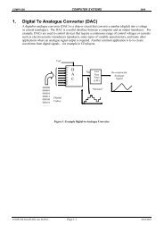
<strong>1.</strong> <strong>Introduction</strong><br />
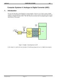
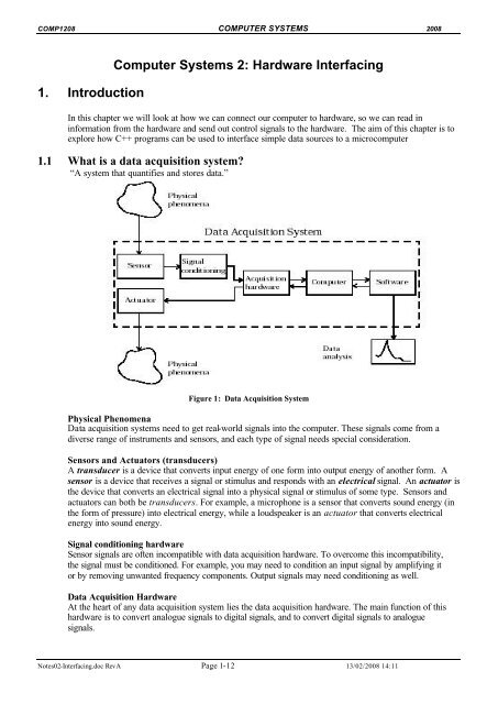
<strong>Computer</strong> <strong>Systems</strong> 2: <strong>Hardware</strong> <strong>Interfacing</strong><br />
In this chapter we will look at how we can connect our computer to hardware, so we can read in<br />
information from the hardware and send out control signals to the hardware. The aim of this chapter is to<br />
explore how C++ programs can be used to interface simple data sources to a microcomputer<br />
<strong>1.</strong>1 What is a data acquisition system<br />
“A system that quantifies and stores data.”<br />
Figure 1: Data Acquisition System<br />
Physical Phenomena<br />
Data acquisition systems need to get real-world signals into the computer. These signals come from a<br />
diverse range of instruments and sensors, and each type of signal needs special consideration.<br />
Sensors and Actuators (transducers)<br />
A transducer is a device that converts input energy of one form into output energy of another form. A<br />
sensor is a device that receives a signal or stimulus and responds with an electrical signal. An actuator is<br />
the device that converts an electrical signal into a physical signal or stimulus of some type. Sensors and<br />
actuators can both be transducers. For example, a microphone is a sensor that converts sound energy (in<br />
the form of pressure) into electrical energy, while a loudspeaker is an actuator that converts electrical<br />
energy into sound energy.<br />
Signal conditioning hardware<br />
Sensor signals are often incompatible with data acquisition hardware. To overcome this incompatibility,<br />
the signal must be conditioned. For example, you may need to condition an input signal by amplifying it<br />
or by removing unwanted frequency components. Output signals may need conditioning as well.<br />
Data Acquisition <strong>Hardware</strong><br />
At the heart of any data acquisition system lies the data acquisition hardware. The main function of this<br />
hardware is to convert analogue signals to digital signals, and to convert digital signals to analogue<br />
signals.<br />
Notes02-<strong>Interfacing</strong>.doc RevA Page 1-12 13/02/2008 14:11
COMP1208 COMPUTER SYSTEMS 2008<br />
The computer<br />
The computer provides a processor, a system clock, a bus to transfer data, and memory and disk space to<br />
store data.<br />
Software<br />
Data acquisition software allows you to exchange information between the computer and the hardware.<br />
For example, typical software allows you to configure the sampling rate of your board, and acquire a<br />
predefined amount of data.<br />
<strong>1.</strong>2 Example of System<br />
In this course we will design a simple system to control temperature on a circuit board.<br />
MOTOR<br />
HEATER<br />
OUT<br />
PORT<br />
<strong>Computer</strong><br />
TEMP<br />
sensor<br />
Analogue to<br />
Digital<br />
Converter<br />
(ADC)<br />
IN<br />
PORT<br />
Figure 2: Example – Temperature Control System<br />
A temperature sensor is connected to the computer via a Analogue to digital converter. The computer<br />
continuously monitors the temperature. If the temperature is too high, a signal is sent to the motor to turn<br />
on a fan until the temperature decreases. If the temperature is too low, a signal is sent by the computer to<br />
the heater to turn it on until the temperature rises to the required level.<br />
Notes02-<strong>Interfacing</strong>.doc RevA Page 2-12 13/02/2008 14:11
COMP1208 COMPUTER SYSTEMS 2008<br />
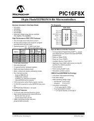
<strong>1.</strong>3 Analogue and Digital Signals<br />
Analogue signals are continuous electrical signals that vary in time as shown the figure below. An<br />
analogue signal is continuously variable and has has an infinite number of values between some<br />
maximum and minimum.<br />
25<br />
Temperature<br />
Degrees C<br />
20<br />
9 12 3 6<br />
Hour<br />
Figure 3: Analogue Signal Example<br />
Analogue signals represent some physical quantity, i.e. they are a ‘MODEL’ of the real quantity.<br />
Digital signals are non-continuous, they change in individual steps. They consist of pulses or digits with<br />
discrete levels or values. The value of each pulse is constant, but there is an abrupt change from one digit<br />
to the next. A binary signal can only have one of two levels, logic 1 or 0. For example:5 Volts -> Logic 1<br />
and 0 Volts -> Logic 0<br />
Voltage<br />
5<br />
0<br />
Time<br />
0 1 1 0 0 1 1 0 ..<br />
Figure 4: Digital Signal Example<br />
Here, then, is a summary of the advantages and disadvantages of the two systems:<br />
Analogue<br />
Advantages<br />
Produces a more 'faithful' reproduction of the physical<br />
quantity.<br />
Usually simple<br />
Disadvantages<br />
Noise and distortion problems<br />
Digital<br />
Advantages<br />
Can be very immune to noise<br />
Signal can be transmitted over long distances.<br />
Disadvantages<br />
Output subject to quantity errors from sampling<br />
Can be complex<br />
Notes02-<strong>Interfacing</strong>.doc RevA Page 3-12 13/02/2008 14:11
COMP1208 COMPUTER SYSTEMS 2008<br />
<strong>1.</strong>4 Serial vs Digital communications<br />
When we wish to connect our computer to external hardware, there are two basic types of communication<br />
ports we can use: serial and parallel.<br />
Serial Communications<br />
source<br />
1<br />
0<br />
1<br />
0<br />
1<br />
1<br />
0<br />
0<br />
1<br />
0 1 0 1 1 0 0<br />
Destination<br />
Parallel Communications<br />
source<br />
1<br />
0<br />
1<br />
0<br />
1<br />
1<br />
0<br />
0<br />
1<br />
0<br />
1<br />
0<br />
1<br />
1<br />
0<br />
0<br />
Destination<br />
Figure 5: Analogue Signal Example<br />
Serial Communications:<br />
When information is sent across a single path, one data bit at a time, this is called serial communications.<br />
There may be number of serial communications ports on your PC, for example the 'D' shaped 9-pin<br />
connector on the back of the computer. This is a serial connector typically uses 2 loops of wire (1 in each<br />
direction) for data communication, plus additional wires to control the flow of information. However, in<br />
any given direction, data is still flowing over a single wire.<br />
Parallel Communications<br />
When information is sent over more wires simultaneously, many bits at a time, this is called parallel<br />
communication. For example, the 25-pin parallel port on your PC has eight data-carrying wires so that<br />
eight bits can be sent simultaneously. Because there are 8 wires to carry the data, the data finishes being<br />
transferred eight times faster than a serial connection.<br />
Notes02-<strong>Interfacing</strong>.doc RevA Page 4-12 13/02/2008 14:11
COMP1208 COMPUTER SYSTEMS 2008<br />
2. <strong>Interfacing</strong> the Parallel Port<br />
2.1 <strong>Introduction</strong><br />
Communications between a computer and an external device require a medium, a common language (a<br />
code, such as ASCII code), and rules for the exchange of signals - called a protocol. The protocol<br />
includes such things as rate at which the exchange of data can take place and how to control the flow of<br />
data when necessary.<br />
This section gives an introduction to interfacing the parallel port.<br />
2.2 Ports<br />
A port is an eight-bit register. It can be accessed by software, but it is also physically connected to a<br />
hardware device, or more usually, it is part of a hardware device. A PC can have 65,536 ports connected<br />
to it, numbered from 0 to FFFF in hex. However, only a small number of these addresses are actually<br />
used.<br />
2.2.1 Common DOS functions in C/C++:<br />
To access a port using the C/C++ language, MicroSoft Visual C++ provides the following functions,<br />
which it should be noted do not conform to ANSI C++ standards:<br />
_inp()<br />
reads a byte from a specified port.<br />
_outp() writes a byte to a specified hardware port.<br />
• _inp(portno) reads a byte from the port with the address portno.<br />
The variable portno must be an unsigned integer between 0 and FFFF hex, and the function returns an integer<br />
value.<br />
• _outp(portno,value) writes a byte to the port with the address portno.<br />
This causes the information in value to be written to the port with the address portno. Again portno must be an<br />
unsigned integer as before, and value is also an integer.<br />
Note these functions will only work if running from DOS or Windows 98, if you are working on<br />
Windows NT/2K/XP, you will need the following .dll loaded: inpout32.dll and inpout32.lib.<br />
How to use inpout32 in VC++ 6.0 application<br />
1 Login as administrator<br />
2 Copy inpout32.dll to your Windows system directory (e.g \Windows\System32),<br />
2 Add the header information below to your VC++ code.<br />
3 Add inpout32.lib file to your project and build.<br />
The following header information is required to map the _inp and _outp functions to Inp32 and Out32<br />
respectively:<br />
// inpout32.dll function prototypes<br />
short _stdcall Inp32(short port);<br />
void _stdcall Out32(short port, short data);<br />
// For compatibility with Win9x code<br />
#define _inp Inp32<br />
#define _outp Out32<br />
Notes02-<strong>Interfacing</strong>.doc RevA Page 5-12 13/02/2008 14:11
COMP1208 COMPUTER SYSTEMS 2008<br />
3. Parallel Port<br />
3.1 <strong>Interfacing</strong> the Parallel Printer Port:<br />
A PC can be connected to a parallel printer by means of a 25-pin connector as shown in<br />
Figure 6 below.<br />
ref<br />
Figure 6: 25-way Female D-Type Connector<br />
There are three ports associated with the computer printer interface as shown.<br />
• DATA Port - access to 8 output pins<br />
• STATUS Port - access to 5 input pins (one inverted)<br />
• CONTROL Port - access to 4 input/output pins (three inverted)<br />
• the remaining 8 pins are grounded<br />
The data port is used to output the printable characters to the printer. The status port is used to input the<br />
information from the printer so that the computer will know when and if to send information to it. The<br />
control port, is used to output control information to the printer.<br />
When a computer is first turned on, the BIOS (Basic Input/Output System) will determine the number of<br />
ports that exist and assign device labels LPT1, LPT2 and LPT3 to them. LPT1 is normally assigned base<br />
address 378h, while LPT2 is assigned 278h. However this may not always be the case.<br />
Address Ports Address Ports<br />
0x378 Data Port for primary parallel port (LPT1)<br />
0x379 Status Port for primary parallel port (LPT1)<br />
0x278 Data Port for second parallel port (LPT2)<br />
0x279 Status Port for second parallel port (LPT2)<br />
0x37A Control Port for primary parallel port (LPT1) 0x27A Control Port for second parallel port (LPT2)<br />
Table 1: Port Addresses<br />
Notes02-<strong>Interfacing</strong>.doc RevA Page 6-12 13/02/2008 14:11
COMP1208 COMPUTER SYSTEMS 2008<br />
3.<strong>1.</strong>1 Software Registers for Standard Parallel Port<br />
Data Port<br />
The base address, usually called the Data Port or Data register is simply used for outputting data on the<br />
Parallel Port’s data lines (pin 2-9). This register is normally a write only port. If you read from the port,<br />
you should get the last byte sent. However, if your port is bi-directional, it is possible to receive data.<br />
The Data Port has the Port Address 0x378, the 0x indicating a hexadecimal number. The Data Port is an<br />
output port when used by the printer, but it can be used by other applications as an input port.<br />
Data register<br />
BIT7 BIT 6 BIT 5 BIT 4 BIT 3 BIT 2 BIT 1 BIT 0<br />
<br />
Pin 9 Pin 8 Pin 7 Pin 6 Pin 5 Pin 4 Pin 3 Pin 2<br />
Figure 7:<br />
Data Port Assignment<br />
Control Port<br />
The Control Port has the Port Address 0x37A and was intended as a write only port. With a printer<br />
attached to the Parallel port, four controls are used, Strobe, Auto LineFeed, Initialise and select printer.<br />
However, it is possible to use these lines for inputs also.<br />
Bit 4 and 5 are internal controls. Bit 4 will enable the IRQ and bit 5 will enable the bi-directional port,<br />
meaning you can input 8 bits using the data registers.<br />
unused unused Enable<br />
BiDir<br />
Enable<br />
IRQ<br />
____<br />
Select<br />
Printer<br />
Initialise<br />
Printer<br />
____<br />
Auto<br />
Linefeed<br />
____<br />
Strobe<br />
BIT 7 BIT 6 BIT 5 BIT 4 BIT 3 BIT 2 BIT 1 BIT 0<br />
<br />
Pin 17 Pin 16 Pin 14 Pin 1<br />
Figure 8:<br />
Control Port Assignment<br />
Status Port<br />
The third port is the Status Port and it has the Port Address 0x379 and is a read only port. Any data<br />
written to this port will be ignored. The Status port is made up of 5 input lines<br />
(Pin 10,11,12,13,15), a IRQ status register and two reserved bits.<br />
Busy<br />
____<br />
ACK<br />
Paper<br />
Out<br />
Select<br />
In<br />
____<br />
Error<br />
___<br />
IRQ<br />
(Not)<br />
Reserved<br />
Reserved<br />
BIT7 BIT 6 BIT 5 BIT 4 BIT 3 BIT 2 BIT 1 BIT 0<br />
› › › › ›<br />
Pin 11 Pin 10 Pin 12 Pin 13 Pin 15<br />
Figure 9:<br />
Status Port Assignment<br />
Notes02-<strong>Interfacing</strong>.doc RevA Page 7-12 13/02/2008 14:11
COMP1208 COMPUTER SYSTEMS 2008<br />
3.2 VC++ Examples<br />
3.2.1 Input Data from Port<br />
Consider the following example, which sets up the parallel port to read from the data port.<br />
Example: Port_in.cpp<br />
//Program to initialise parallel port to read from an Application Card<br />
#include <br />
#include <br />
using namespace std;<br />
int main()<br />
{<br />
int data;<br />
_outp(0x37A_PORT,0x20);<br />
data = _inp(0x378);<br />
// set bit 5 on Control Reg -> read data<br />
// byte read from the Data Port<br />
cout
COMP1208 COMPUTER SYSTEMS 2008<br />
This above program is modified to include a function which handles the read from parallel port and also<br />
the header is modified to include the function prototypes for the inpout32.dll required use on Windows<br />
NT/2000/XP:<br />
//Program to initialise parallel port to read from an Application Card<br />
// C/C++ Library includes<br />
#include <br />
#include <br />
using namespace std;<br />
// inpout32.dll function prototypes required for Windows NT/2000/XP<br />
short _stdcall Inp32(short port);<br />
void _stdcall Out32(short port, short data);<br />
// For compatibility with Win9x code<br />
#define _inp Inp32<br />
#define _outp Out32<br />
// Parallel Port Addresses<br />
#define CNTRL_PORT 0x37A<br />
#define DATA_PORT 0x378<br />
// Printer control port location<br />
// Printer data port location<br />
// Function Prototype<br />
int read_pport( void );<br />
int main()<br />
{<br />
int data;<br />
data = read_pport();<br />
//call function to read from the Data Port<br />
cout
COMP1208 COMPUTER SYSTEMS 2008<br />
3.2.2 Output Data to Port<br />
Consider the following example, which sets up the parallel port to write to the data port.<br />
Example: Port_out.cpp<br />
// Program to initialise parallel port to write to an Application Card<br />
// IDE: Microsoft VC 6.0<br />
// C/C++ Library includes<br />
#include <br />
#include <br />
using namespace std;<br />
// Parallel Port Addresses<br />
#define CNTRL_PORT 0x37A<br />
#define DATA_PORT 0x378<br />
int main()<br />
{<br />
_outp(CNTRL_PORT,0x01);<br />
_outp(DATA_PORT, 0xA7);<br />
return 0;<br />
}<br />
// Printer control port location<br />
// Printer data port location<br />
// set bit 0 on Control Reg -> write data<br />
// write 0xA7 to parallel port<br />
Using the _outp function, the control port is set to 0x01, i.e. 0000 0001 2.<br />
_outp(CNTRL_PORT,0x01);<br />
unused unused Enable Enable IRQ Select Initialise Auto Strobe<br />
BiDir<br />
Printer Printer Linefeed<br />
0 0 0 0 0 0 0 1<br />
This sets the parallel interface to write mode. Thus using the _outp function, data is written to the data<br />
port.<br />
_outp(DATA_PORT,0xA7);<br />
D7 D6 D5 D4 D3 D2 D1 D0<br />
1 0 1 0 0 1 1 1<br />
Notes02-<strong>Interfacing</strong>.doc RevA Page 10-12 13/02/2008 14:11
COMP1208 COMPUTER SYSTEMS 2008<br />
This above program is modified to include a function which handles the write to the parallel port and also<br />
the header is modified to include the function prototypes for the inpout32.dll required use on Windows<br />
NT/2000/XP:<br />
Example: Port_out.cpp<br />
// Program to initialise parallel port to write to an Application Card<br />
// IDE: Microsoft VC 6.0<br />
// C/C++ Library includes<br />
#include <br />
#include <br />
using namespace std;<br />
// inpout32.dll function prototypes required for Windows NT/2000/XP<br />
short _stdcall Inp32(short port);<br />
void _stdcall Out32(short port, short data);<br />
// For compatibility with Win9x code<br />
#define _inp Inp32<br />
#define _outp Out32<br />
// Parallel Port Addresses<br />
#define CNTRL_PORT 0x37A<br />
#define DATA_PORT 0x378<br />
// Printer control port location<br />
// Printer data port location<br />
// Function Prototype<br />
int write_pport( int data);<br />
int main()<br />
{<br />
write_pport(0xA7);<br />
// write 0xA7 to parallel port<br />
}<br />
return 0;<br />
// Function to write to the parallel port<br />
void write_pport( int data )<br />
{<br />
_outp(CNTRL_PORT,0x00); // reset bit 0 on Control Register<br />
_outp(CNTRL_PORT,0x01); // set bit 0 on Control Reg -> write data<br />
_outp(DATA_PORT,data); // write data to data port<br />
_outp(CNTRL_PORT,0x00); // reset bit 0 on Control Register<br />
}<br />
Notes02-<strong>Interfacing</strong>.doc RevA Page 11-12 13/02/2008 14:11
COMP1208 COMPUTER SYSTEMS 2008<br />
3.2.3 Input and Output Data<br />
Consider the following example, which reads in data from the parallel port and writes this data back out to<br />
the parallel port.<br />
Example 1: read_write_port.cpp<br />
// Program to initialise parallel port to write to and read from an<br />
// Application Card<br />
// IDE: Microsoft VC 6.0<br />
// C/C++ Library includes<br />
#include <br />
#include <br />
using namespace std;<br />
// inpout32.dll function prototypes required for Windows NT/2000/XP<br />
short _stdcall Inp32(short port);<br />
void _stdcall Out32(short port, short data);<br />
// For compatibility with Win9x code<br />
#define _inp Inp32<br />
#define _outp Out32<br />
// Parallel Port Addresses<br />
#define CNTRL_PORT 0x37A<br />
#define DATA_PORT 0x378<br />
// Printer control port location<br />
// Printer data port location<br />
int main()<br />
{<br />
int data;<br />
_outp(CNTRL_PORT,0x20);<br />
data = _inp(DATA_PORT);<br />
_outp(CNTRL_PORT,0x00);<br />
_outp(CNTRL_PORT,0x01);<br />
_outp(DATA_PORT,data);<br />
// set bit 5 on Control Reg -> read data<br />
// byte read from the Data Port<br />
// reset bit 5 on Control Register<br />
// set bit 0 on Control Reg -> write data<br />
// write data to data port<br />
}<br />
return 0;<br />
Exercise:<br />
Modify this example, to use functions for read and write to parallel port as used in the previous section/<br />
Notes02-<strong>Interfacing</strong>.doc RevA Page 12-12 13/02/2008 14:11
COMP1208 COMPUTER SYSTEMS 2008<br />
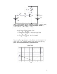
3.3 Exercises<br />
Given the following circuit diagram showing a temperature sensor connected via ADC to the parallel port<br />
of the PC, write a C++ function to read the temperature and return the temperature value as an integer to<br />
the calling function.<br />
Analog<br />
votage<br />
0-2.55V<br />
Digital 8-bit<br />
0x00 to 0xFF<br />
Parallel Port<br />
Temperature<br />
Sensor<br />
ADC<br />
Data Reg<br />
0x378<br />
Control Reg 0x37A<br />
00100000<br />
Bit 5<br />
set for input<br />
Figure 10: Applications Board Inputs<br />
Given the following circuit diagram showing a Fan and heater connected via parallel port to the PC, write<br />
two C++ functions to<br />
• turn on the heater<br />
• turn on the fan<br />
LEDS<br />
7 6 5 4 3 2 1 0<br />
Data Reg Bit 6 or 7 -> Motor on<br />
Data Reg Bit 5 ->. Heater on<br />
Direction<br />
Relay<br />
Parallel Port<br />
Data Reg<br />
0x378<br />
MOTOR<br />
HEATER<br />
Control Reg 0x37A<br />
00000001<br />
Bit 0<br />
set for<br />
output<br />
Figure 11: Applications Board Outputs<br />
Notes02-<strong>Interfacing</strong>.doc RevA Page 13-12 13/02/2008 14:11