

Human Gait-Based Bipedal Walking Robot Design in Progress - KAIST
Human Gait-Based Bipedal Walking Robot Design in Progress - KAIST
Human Gait-Based Bipedal Walking Robot Design in Progress - KAIST

Create successful ePaper yourself
Turn your PDF publications into a flip-book with our unique Google optimized e-Paper software.
International Conference on Control, Automation and Systems 2010<br />
Oct. 27-30, 2010 <strong>in</strong> KINTEX, Gyeonggi-do, Korea<br />
<strong>Human</strong> <strong>Gait</strong>-<strong>Based</strong> <strong>Bipedal</strong> <strong>Walk<strong>in</strong>g</strong> <strong>Robot</strong> <strong>Design</strong> <strong>in</strong> <strong>Progress</strong><br />
Eunchul Jeon 1 and Sungho Jo 2<br />
1 Department of Computer Science, Korea Advanced Institute of Science and Technology, Daejeon, Korea<br />
(Tel : Tel : +82-2-000-0000; E-mail: jsharp83@kaist.ac.kr)<br />
2 Department of Computer Science, Korea Advanced Institute of Science and Technology, Daejeon, Korea<br />
(Tel : +81-3-000-0000; E-mail: shjo@cs.kaist.ac.kr)<br />
Abstract: This work presents the mechanical human gait-based 3D bipedal walk<strong>in</strong>g robot. The robot mimics human<br />
walk<strong>in</strong>g through the push-off mechanism at the ankle, the passive knee bend<strong>in</strong>g mechanism, and the simple lateral balance<br />
control. To generate walk<strong>in</strong>g, it uses simple waveforms which are derived from human gait data. The prelim<strong>in</strong>ary<br />
experiment demonstrates that the robot walks stably.<br />
Keywords: <strong>Bipedal</strong> walk<strong>in</strong>g robot<br />
1. INTRODUCTION<br />
<strong>Bipedal</strong> robot locomotion has been one of daunt<strong>in</strong>g<br />
research topics <strong>in</strong> robotics society. As po<strong>in</strong>ted <strong>in</strong> [1],<br />
the biped robot design strategy can be <strong>in</strong>clusively classified<br />
<strong>in</strong> two approaches. First approach is based on precise<br />
jo<strong>in</strong>t-angle control, and ma<strong>in</strong>ly apply the zero moment<br />
po<strong>in</strong>t (ZMP) pr<strong>in</strong>ciple to realize stable walk<strong>in</strong>g.<br />
Many bipedal walkers have been designed with the control<br />
paradigm [2][3][4]. Mostly, they tend to walk with<br />
knee bend<strong>in</strong>g kept to ma<strong>in</strong>ta<strong>in</strong> stability. The pose is to<br />
m<strong>in</strong>imize weight acceptance impact dur<strong>in</strong>g the ground<br />
touch. Hip actuation is a ma<strong>in</strong> forward thrust source<br />
unlikely to humans, and ankle-level push-off is unused<br />
much because stability ma<strong>in</strong>tenance is difficult. Because<br />
they require high precision and frequent response for control,<br />
this strategy requires high energy consumption. The<br />
other approach is based on passive-dynamic pr<strong>in</strong>ciple [5].<br />
A robot <strong>in</strong> this category is called passive-dynamic walker<br />
(PDW). PDWs rule out precise jo<strong>in</strong>t angle control with<br />
large energy demands, and pursue a design powered by<br />
human-like efficient energy use. This approach may be<br />
comparable to humans <strong>in</strong> terms of gait appearance, energy<br />
use and control strategy. However, their mechanism<br />
and control strategy may h<strong>in</strong>der robust behavior implementations.<br />
This work reports the first stage result to develop a<br />
simple bipedal walk<strong>in</strong>g robot. Our mechanical design of<br />
the robot is proposed to evaluate three <strong>in</strong>terest<strong>in</strong>g po<strong>in</strong>ts:<br />
1. <strong>Human</strong> gait-based control <strong>in</strong>put trajectory<br />
2. Forward thrust at ankle region by potential energy<br />
3. Passive knee bend<strong>in</strong>g mechanism<br />
4. Simple lateral balance control<br />
2. MECHANICAL DESIGN<br />
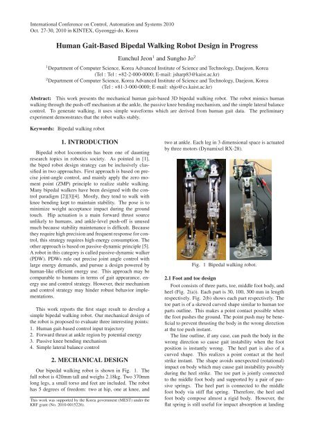
Our bipedal walk<strong>in</strong>g robot is shown <strong>in</strong> Fig. 1. The<br />
full robot is 420mm tall and weighs 2.18kg. Two 370mm<br />
long legs, a small torso and feet are <strong>in</strong>cluded. The robot<br />
has 5 degrees of freedom: two at hip, one at knee, and<br />
This work was supported by the Korea government (MEST) under the<br />
KRF grant (No. 2010-0015226).<br />
two at ankle. Each leg <strong>in</strong> 3 dimensional space is actuated<br />
by three motors (Dynamixel RX-28).<br />
Fig. 1 <strong>Bipedal</strong> walk<strong>in</strong>g robot.<br />
2.1 Foot and toe design<br />
Foot consists of three parts, toe, middle foot body, and<br />
heel (Fig. 2(a)). Each part is 30, 100, 300 mm <strong>in</strong> length<br />
respectively. Fig. 2(b) shows each part respectively. The<br />
toe part is of a skewed curved shape similar to human toe<br />
parts outl<strong>in</strong>e. This makes a po<strong>in</strong>t contact possible when<br />
the foot pushes the ground. The po<strong>in</strong>t push may be beneficial<br />
to prevent thrust<strong>in</strong>g the body <strong>in</strong> the wrong direction<br />
at the toe push <strong>in</strong>stant.<br />
The l<strong>in</strong>e outl<strong>in</strong>e, if any case, can push the body <strong>in</strong> the<br />
wrong direction so cause gait <strong>in</strong>stability when the foot<br />
position is <strong>in</strong>stantly wrong. The heel part is also of a<br />
curved shape. This realizes a po<strong>in</strong>t contact at the heel<br />
strike <strong>in</strong>stant. The shape avoids unexpected (rotational)<br />
impact on body which may cause gait <strong>in</strong>stability possibly<br />
dur<strong>in</strong>g the heel strike. The toe part is jo<strong>in</strong>tly connected<br />
to the middle foot body and supported by a pair of passive<br />
spr<strong>in</strong>gs. The heel part is connected to the middle<br />
foot body via stiff flat spr<strong>in</strong>g. Therefore, the heel and<br />
foot body compose almost a rigid body. However, the<br />
flat spr<strong>in</strong>g is still useful for impact absorption at land<strong>in</strong>g
phase. The whole foot bottom is covered by moderate<br />
sponge and rubber, which are used on table tennis rackets.<br />
They provide the damp<strong>in</strong>g effect like the foot sk<strong>in</strong>.<br />
Especially the heel part has a ticker rubber layer for stable<br />
land<strong>in</strong>g. A pair of passive spr<strong>in</strong>gs between the heel<br />
and the foot body has also a role of damp<strong>in</strong>g the body <strong>in</strong><br />
land<strong>in</strong>g (heel-strike). A pair of passive spr<strong>in</strong>gs between<br />
the toe and the foot body is critical <strong>in</strong> this robot walk<strong>in</strong>g.<br />
Dur<strong>in</strong>g stance-to-sw<strong>in</strong>g transition, the foot body is<br />
off the ground, but the toe part rema<strong>in</strong>s contacted on the<br />
ground. The lift of foot body pulls the spr<strong>in</strong>gs, therefore,<br />
the spr<strong>in</strong>gs earn the potential energy, which is released to<br />
thrust the upper body forward by push<strong>in</strong>g the ground at<br />
the moment of push-off. In terms of its role, the spr<strong>in</strong>g is<br />
similar to the archilles tendon <strong>in</strong> human body. This mimics<br />
energetically effective human walk<strong>in</strong>g mechanism to<br />
use powerful impulses at push-off [6]. Passive-dynamicsbased<br />
walk<strong>in</strong>g robots use the similar strategies to m<strong>in</strong>imize<br />
motor power requirements for push-off performance<br />
[7][8][9]. The robots usually equip the push-off spr<strong>in</strong>gs<br />
around ankle jo<strong>in</strong>t to achieve ankle-extension. However,<br />
<strong>in</strong> our robot, the push-off spr<strong>in</strong>gs operates via jo<strong>in</strong>t between<br />
the toe and the foot body. This design is due to<br />
clear reasons. Other robots generally have solid feet so<br />
there is no other choice but ankle jo<strong>in</strong>t to rotate feet. With<br />
solid feet, ankle extension <strong>in</strong> stance leg tends to require<br />
large potential energy <strong>in</strong> spr<strong>in</strong>g to lift the upper body, but<br />
it produces large forward thrust once the foot is off the<br />
ground. Therefore, it is difficult to ma<strong>in</strong>ta<strong>in</strong> gait stability.<br />
To moderate the issue, robots usually have curved<br />
foot bottoms. However, they may still be able to produce<br />
high forward thrust and require careful control to<br />
achieve stable sw<strong>in</strong>g leg motions dur<strong>in</strong>g sw<strong>in</strong>g phase and<br />
stable ground touch at sw<strong>in</strong>g-to-stance transition. For example,<br />
push-off process is mechanically constra<strong>in</strong>ed just<br />
after heel strike <strong>in</strong> [10]. In our robot, a proper amount<br />
of potential energy <strong>in</strong> spr<strong>in</strong>g is required for jo<strong>in</strong>t extension<br />
between the toe and the foot body, which is powerful<br />
enough to perform push-off. The flat feet <strong>in</strong> our robot<br />
guarantees more robust posture than curved feet aga<strong>in</strong>st<br />
external pushes.<br />
2.2 Ankle design<br />
The shank and foot are jo<strong>in</strong>ted via ankle jo<strong>in</strong>t with a<br />
motor. The motor body is rigidly attached to the end of<br />
shank and its shaft rotates the foot <strong>in</strong> the sagittal plane.<br />
Fig. 2 Foot design.<br />
From the heel strike to toe-ff, the motor helps upper body<br />
moves around the ankle jo<strong>in</strong>t of stance leg as if <strong>in</strong>verted<br />
pendulum does. It is important to note that the motor is<br />
not a major forward thrust generator for forward thrust<br />
but the spr<strong>in</strong>gs on the foot (details <strong>in</strong> previous section)<br />
is. However, ankle rotation can affect the push-off performance<br />
critically because push-off thrust is effectively<br />
obta<strong>in</strong>ed when foot rotation and body position are well<br />
timely synchronized. Therefore, the motor is a key operator<br />
for gait efficiency and stability.<br />
Fig. 3 Ankle design.<br />
The ankle motion is also <strong>in</strong>fluential on knee bend<strong>in</strong>g<br />
mechanism, which will be discussed <strong>in</strong> next section. A<br />
passive spr<strong>in</strong>g is located on each side of the ankle to buttress<br />
the shank laterally as well as damp the contact impact<br />
<strong>in</strong> the coronal plane. Space between legs is a little<br />
wider at foot than at hip. The posture is beneficial to keep<br />
lateral stability. Therefore, the foot is designed to be <strong>in</strong>wardly<br />
a little tilt by locat<strong>in</strong>g a stiffer spr<strong>in</strong>g <strong>in</strong>side than<br />
outside. Dur<strong>in</strong>g push-off, the <strong>in</strong>side spr<strong>in</strong>g helps pull a<br />
stance leg <strong>in</strong> order to keep lateral stability from outward<br />
sway. The spr<strong>in</strong>gs stiffness is decided experimentally.<br />
2.3 Knee design<br />
Lock<strong>in</strong>g mechanism is designed at knee to prevent hyperextension.<br />
Knee jo<strong>in</strong>t is locked after mid-sw<strong>in</strong>g up<br />
to the end of stance phase and unlocked dur<strong>in</strong>g the rema<strong>in</strong>der<br />
phase. As <strong>in</strong> Fig. 4, the lock<strong>in</strong>g mechanism is<br />
basically a type of latch. The latch arm is attached to the<br />
shank via h<strong>in</strong>ge with a torsion spr<strong>in</strong>g. The latch body is<br />
rigidly attached to the thigh At the tim<strong>in</strong>g of push-off, ankle<br />
angle reaches a threshold value, then, a latch arm with<br />
a hook is pulled by a str<strong>in</strong>g which is connected from the<br />
foot via two pulleys, and detached from the latch body.<br />
The pulleys allow the foot rotation (push-off) to generate<br />
l<strong>in</strong>ear pull<strong>in</strong>g force which is transferred through the<br />
str<strong>in</strong>g. The detachment allows the knee bend<strong>in</strong>g. After<br />
unlock<strong>in</strong>g, knee flexes. The tip of latch body is connected<br />
to the top of shank through a spr<strong>in</strong>g. While knee<br />
bends, the spr<strong>in</strong>g ga<strong>in</strong>s energy, which is used to hold the<br />
shank at a certa<strong>in</strong> degree. Then, <strong>in</strong>ertial force drives the<br />
shank back to the extended position dur<strong>in</strong>g forward sw<strong>in</strong>g<br />
phase. While extend<strong>in</strong>g the shank via knee jo<strong>in</strong>t, the ankle<br />
angle rema<strong>in</strong>s less than the threshold value, and str<strong>in</strong>g<br />
does not pull the latch arm. The torsion spr<strong>in</strong>g clicks the<br />
hook on the top of the latch arm <strong>in</strong>to the slit of the latch<br />
surface to engage lock<strong>in</strong>g, Then, leg is robustly extended.<br />
Both the hook and latch surfaces are of curvature. The<br />
hook moves along the latch surface with a l<strong>in</strong>e contact to<br />
m<strong>in</strong>imize friction. The str<strong>in</strong>g <strong>in</strong>cludes two spr<strong>in</strong>gs serially<br />
and <strong>in</strong>termediately. The spr<strong>in</strong>gs stra<strong>in</strong> the str<strong>in</strong>g m<strong>in</strong>-
imally even with no ankle-driven pull<strong>in</strong>g force. Therefore,<br />
they prevent the str<strong>in</strong>g from leav<strong>in</strong>g out of pulleys.<br />
This mechanically passive mechanism requires no extra<br />
electric power for operation.<br />
{<br />
locked if θa
(a)<br />
1998 IEEE International Conference on <strong>Robot</strong>ics<br />
and Automation, 1998. Proceed<strong>in</strong>gs, vol. 2, 1998.<br />
[3] S. Kajita, F. Kanehiro, K. Kaneko, K. Fujiwara,<br />
K. Harada, K. Yokoi, and H. Hirukawa, “Biped<br />
walk<strong>in</strong>g pattern generation by us<strong>in</strong>g preview control<br />
of zero-moment po<strong>in</strong>t,” <strong>in</strong> IEEE International Conference<br />
on <strong>Robot</strong>ics and Automation, vol. 2. Citeseer,<br />
2003, pp. 1620–1626.<br />
[4] I. Park, J. Kim, J. Lee, and J. Oh, “Mechanical design<br />
of humanoid robot platform khr-3 (kaist humanoid<br />
robot-3: Hubo),” <strong>in</strong> IEEE/RAS International<br />
Conference on <strong>Human</strong>oid <strong>Robot</strong>s, 2005.<br />
[5] T. McGeer, “Passive dynamic walk<strong>in</strong>g,” The International<br />
Journal of <strong>Robot</strong>ics Research, vol. 9, no. 2,<br />
p. 62, 1990.<br />
[6] J. Donelan, R. Kram, and A. Kuo, “Mechanical<br />
work for step-to-step transitions is a major determ<strong>in</strong>ant<br />
of the metabolic cost of human walk<strong>in</strong>g,”<br />
Journal of Experimental Biology, vol. 205, no. 23,<br />
p. 3717, 2002.<br />
[7] S. Coll<strong>in</strong>s, A. Ru<strong>in</strong>a, R. Tedrake, and M. Wisse,<br />
“Efficient bipedal robots based on passive-dynamic<br />
walkers,” Science, vol. 307, no. 5712, p. 1082,<br />
2005.<br />
[8] S. Coll<strong>in</strong>s and A. Ru<strong>in</strong>a, “A bipedal walk<strong>in</strong>g robot<br />
with efficient and human-like gait,” <strong>in</strong> <strong>Robot</strong>ics and<br />
Automation, 2005. ICRA 2005. Proceed<strong>in</strong>gs of the<br />
2005 IEEE International Conference on, 2005, pp.<br />
1983–1988.<br />
[9] M. Wisse, G. Feliksdal, J. Van Frankkenhuyzen,<br />
and B. Moyer, “Passive-based walk<strong>in</strong>g robot,” IEEE<br />
<strong>Robot</strong>ics & Automation Magaz<strong>in</strong>e, vol. 14, no. 2,<br />
pp. 52–62, 2007.<br />
[10] A. Kuo, “Energetics of actively powered locomotion<br />
us<strong>in</strong>g the simplest walk<strong>in</strong>g model,” Journal of<br />
Biomechanical Eng<strong>in</strong>eer<strong>in</strong>g, vol. 124, p. 113, 2002.<br />
(b)<br />
Fig. 7 (a) Snapshots of robot walk<strong>in</strong>g from front view,<br />
and (b) from side view.