Download API's catalog - Thermo/Cense Inc.
Download API's catalog - Thermo/Cense Inc.
Download API's catalog - Thermo/Cense Inc.

Create successful ePaper yourself
Turn your PDF publications into a flip-book with our unique Google optimized e-Paper software.
API 6010 G Installation and Setup<br />
AC Input<br />
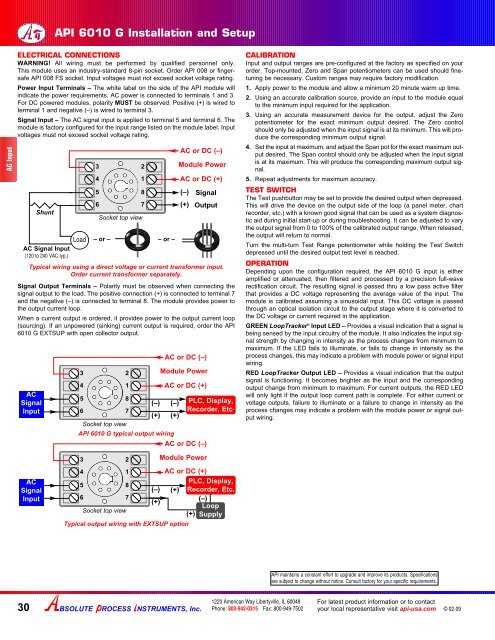
ELECTRICAL CONNECTIONS<br />
WARNING! All wiring must be performed by qualified personnel only.<br />
This module uses an industry-standard 8-pin socket. Order API 008 or fingersafe<br />
API 008 FS socket. Input voltages must not exceed socket voltage rating.<br />
Power Input Terminals – The white label on the side of the API module will<br />
indicate the power requirements. AC power is connected to terminals 1 and 3.<br />
For DC powered modules, polarity MUST be observed. Positive (+) is wired to<br />
terminal 1 and negative (–) is wired to terminal 3.<br />
Signal Input – The AC signal input is applied to terminal 5 and terminal 6. The<br />
module is factory configured for the input range listed on the module label. Input<br />
voltages must not exceed socket voltage rating.<br />
Shunt<br />
AC Signal Input<br />
(120 to 240 VAC typ.)<br />
Load<br />
3<br />
4<br />
5<br />
6<br />
Socket top view<br />
– or –<br />
AC or DC (–)<br />
Module Power<br />
AC or DC (+)<br />
(–) Signal<br />
(+) Output<br />
Signal Output Terminals – Polarity must be observed when connecting the<br />
signal output to the load. The positive connection (+) is connected to terminal 7<br />
and the negative (–) is connected to terminal 8. The module provides power to<br />
the output current loop.<br />
When a current output is ordered, it provides power to the output current loop<br />
(sourcing). If an unpowered (sinking) current output is required, order the API<br />
6010 G EXTSUP with open collector output.<br />
2<br />
1<br />
8<br />
7<br />
– or –<br />
Typical wiring using a direct voltage or current transformer input.<br />
Order current transformer separately.<br />
AC<br />
Signal<br />
Input<br />
3<br />
4<br />
5<br />
6<br />
Socket top view<br />
2<br />
1<br />
8<br />
7<br />
(–)<br />
(+)<br />
AC or DC (–)<br />
Module Power<br />
AC or DC (+)<br />
(–)<br />
(+)<br />
API 6010 G typical output wiring<br />
AC or DC (–)<br />
PLC, Display,<br />
Recorder, Etc.<br />
CALIBRATION<br />
Input and output ranges are pre-configured at the factory as specified on your<br />
order. Top-mounted, Zero and Span potentiometers can be used should finetuning<br />
be necessary. Custom ranges may require factory modification.<br />
1. Apply power to the module and allow a minimum 20 minute warm up time.<br />
2. Using an accurate calibration source, provide an input to the module equal<br />
to the minimum input required for the application.<br />
3. Using an accurate measurement device for the output, adjust the Zero<br />
potentiometer for the exact minimum output desired. The Zero control<br />
should only be adjusted when the input signal is at its minimum. This will produce<br />
the corresponding minimum output signal.<br />
4. Set the input at maximum, and adjust the Span pot for the exact maximum output<br />
desired. The Span control should only be adjusted when the input signal<br />
is at its maximum. This will produce the corresponding maximum output signal.<br />
5. Repeat adjustments for maximum accuracy.<br />
TEST SWITCH<br />
The Test pushbutton may be set to provide the desired output when depressed.<br />
This will drive the device on the output side of the loop (a panel meter, chart<br />
recorder, etc.) with a known good signal that can be used as a system diagnostic<br />
aid during initial start-up or during troubleshooting. It can be adjusted to vary<br />
the output signal from 0 to 100% of the calibrated output range. When released,<br />
the output will return to normal.<br />
Turn the multi-turn Test Range potentiometer while holding the Test Switch<br />
depressed until the desired output test level is reached.<br />
OPERATION<br />
Depending upon the configuration required, the API 6010 G input is either<br />
amplified or attenuated, then filtered and processed by a precision full-wave<br />
rectification circuit. The resulting signal is passed thru a low pass active filter<br />
that provides a DC voltage representing the average value of the input. The<br />
module is calibrated assuming a sinusoidal input. This DC voltage is passed<br />
through an optical isolation circuit to the output stage where it is converted to<br />
the DC voltage or current required in the application.<br />
GREEN LoopTracker ® Input LED – Provides a visual indication that a signal is<br />
being sensed by the input circuitry of the module. It also indicates the input signal<br />
strength by changing in intensity as the process changes from minimum to<br />
maximum. If the LED fails to illuminate, or fails to change in intensity as the<br />
process changes, this may indicate a problem with module power or signal input<br />
wiring.<br />
RED LoopTracker Output LED – Provides a visual indication that the output<br />
signal is functioning. It becomes brighter as the input and the corresponding<br />
output change from minimum to maximum. For current outputs, the RED LED<br />
will only light if the output loop current path is complete. For either current or<br />
voltage outputs, failure to illuminate or a failure to change in intensity as the<br />
process changes may indicate a problem with the module power or signal output<br />
wiring.<br />
AC<br />
Signal<br />
Input<br />
3<br />
4<br />
5<br />
6<br />
Socket top view<br />
2<br />
1<br />
8<br />
7<br />
Module Power<br />
Typical output wiring with EXTSUP option<br />
AC or DC (+)<br />
PLC, Display,<br />
(–) (+) Recorder, Etc.<br />
(+)<br />
(–)<br />
Loop<br />
(+) Supply<br />
API maintains a constant effort to upgrade and improve its products. Specifications<br />
are subject to change without notice. Consult factory for your specific requirements.<br />
30<br />
BSOLUTE ROCESS NSTRUMENTS, <strong>Inc</strong>.<br />
1220 American Way Libertyville, IL 60048<br />
Phone: 800-942-0315 Fax: 800-949-7502<br />
For latest product information or to contact<br />
your local representative visit api-usa.com<br />
© 02-09