ROTAX MOJO MAX EURO Challenge Technical Regulations ... - EIKO
ROTAX MOJO MAX EURO Challenge Technical Regulations ... - EIKO
ROTAX MOJO MAX EURO Challenge Technical Regulations ... - EIKO

Create successful ePaper yourself
Turn your PDF publications into a flip-book with our unique Google optimized e-Paper software.
<strong>ROTAX</strong> <strong>MOJO</strong> <strong>MAX</strong> <strong>EURO</strong> <strong>Challenge</strong><br />
<strong>Technical</strong> <strong>Regulations</strong> 2007<br />
(version 2006.11.01.rg2)<br />
Article 1: Categories<br />
Article 2: General Prescriptions<br />
Article 3: Kart Chassis<br />
Article 4: Kart Safety<br />
Article 5: Engines<br />
Article 6: Engine Sealing<br />
Article 7: No<br />
Article 8: No<br />
Article 9: Engine <strong>Technical</strong> Specification<br />
The CIK-FIA <strong>Technical</strong> regulation also apply for the Rotax Mojo Max Euro <strong>Challenge</strong> 2007.<br />
The English text is the authentic version.<br />
<strong>ROTAX</strong> <strong>MOJO</strong> <strong>MAX</strong> <strong>EURO</strong> CHALLENGE, reserves the right to issue additional statements concerning the<br />
<strong>Technical</strong> <strong>Regulations</strong> (previously approved by the ASN proposing the series and the CIK-FIA) from time to<br />
time following the agreement of the ASN presenting the ASN and the CIK-FIA, and all such statements will be<br />
issued to all registered competitors by way of Competitors’ Bulletins at the race meeting, or posted to the<br />
address detailed on the Series Registration Form.<br />
Article 1 - CATEGORIES<br />
Engines used in the <strong>ROTAX</strong> <strong>MOJO</strong> <strong>MAX</strong> <strong>EURO</strong> CHALLENGE divided into the following groups are:<br />
- <strong>ROTAX</strong> FR 125 Junior Max, Cylinder capacity of 125 cc<br />
- <strong>ROTAX</strong> FR 125 <strong>MAX</strong>, Cylinder capacity of 125 cc<br />
- <strong>ROTAX</strong> FR 125 <strong>MAX</strong> Master, Cylinder capacity of 125 cc<br />
- <strong>ROTAX</strong> FR 125 DD, Cylinder capacity of 125 cc, 2 - speed<br />
Article 2 – GENERAL PRESCRIPTIONS<br />
2.1 – The kart and any modification must conform to the specific regulations of the<br />
categories in which the kart is entered, or to the General Prescriptions.<br />
2.2 – Application of the General Prescriptions These General Prescriptions apply to all categories in the<br />
event that they are not subject to specific regulations.<br />
2.3 – It is the duty of every Entrant to prove to the Scrutineers and to the Stewards that his kart<br />
integrally complies with the <strong>Regulations</strong> throughout the event.<br />
2.4 – Modifications Any modification is forbidden if it is not explicitly authorised by an article of these<br />
<strong>Regulations</strong> or for safety reasons decided by the CIK-FIA. By modification are meant any operations likely<br />
to change the initial aspect, the dimensions, the drawings or the photographs of an original homologated<br />
part.
2.5 – Adjunction of material or parts Any adjunction or fixation of material or of parts is forbidden if it is<br />
not expressly authorised by an article of these <strong>Regulations</strong> or for safety reasons decided by the CIK-FIA.<br />
Removed material may not be used again. Rebuilding the frame geometry, following an accident, is<br />
authorised by adjunction of the materials necessary for the repairs (additional metal for welding, etc.);<br />
other parts which may be worn out or damaged may not be repaired by addition or fixation of material,<br />
unless an article of these <strong>Regulations</strong> authorises it exceptionally.<br />
Article 3 - KART<br />
CHASSIS Amount of equipment<br />
3.0 Scrutineering<br />
A mandatory check will be carried out before the start.<br />
It must be possible to identify the homologated equipment by the technical descriptions (drawings,<br />
dimensions, etc.) on the Homologation Form.<br />
For any used equipment, which has been homologated, every competitor shall be able to submit the<br />
relevant Homologation Forms.<br />
Identification and control It must be possible to identify the homologated equipment<br />
3.1 Drivers will be allowed one chassis only . However if damage occurs to the chassis, which has been<br />
scrutinized for the meeting, if in the opinion of the scrutineer it is not practical to repair in time, one<br />
alternative chassis of the same make as the damaged chassis may be scrutinized, in order to continue<br />
the meeting.<br />
3.2 Chassis in 125 Junior <strong>MAX</strong>, 125 <strong>MAX</strong> and 125 <strong>MAX</strong> Master<br />
must have a valid 2003 or newer CIK-Homologation, no front brakes are allowed in Max Junior<br />
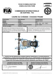
3.3 125 <strong>MAX</strong> DD2 class.<br />
Chassis approved by BRP-<strong>ROTAX</strong> only are allowed to be used. Chassis must be designed according to<br />
CIK rules for shifter classes (front and rear brakes mandatory). Brake system must have a valid<br />
CIK homologation. <strong>ROTAX</strong> Rear Tire Protection System is mandatory to be used. Approved chassis will<br />
be listed at "www.maxchallenge-rotax.com".<br />
3.4 The rear shaft (axle) must have a maximum external diameter of 50 mm and a minimum wall<br />
thickness of 1.9 mm at all points. The rear shaft thickness must at all points (except in key housings) be<br />
as a minimum:<br />
Table of equivalence according to external diameters<br />
Max. External diameter (mm) Min. thickness (mm)<br />
50 1.9<br />
49 2.0<br />
48 2.0<br />
47 2.1<br />
46 2.2<br />
45 2.3<br />
44 2.4<br />
43 2.5<br />
42 2.6<br />
41 2.8<br />
40 2.9<br />
3.5 <strong>Technical</strong> specifications<br />
Wheelbase: Minimum: 101 cm, Maximum 107 cm<br />
Overall length: 182cm maximum without a front and/or rear fairing<br />
Overall width: 140 cm maximum.<br />
Height: 65 cm maximum from the ground, seat excluded.<br />
No part may project beyond the quadrilateral formed by the front fairing, rear bumper and the wheels.<br />
3.6 Weight<br />
The weights given are absolute minima and it must be possible to check them at any moment of a<br />
competition and read on the display of the scales whatever their measuring precision, the Driver being<br />
normally equipped for the race (helmet, goggles, gloves and shoes). Any infringement found during a<br />
random check during or at the end of an event shall result in the Driver and/or Entrant being excluded<br />
from that particular Heat, Qualifying Practice or Race.
3.7 Ballast<br />
It is authorised to adjust the weight of the kart with one or several ballasts subject to their being solid<br />
blocks, fixed to the chassis or to the seat by means of tools with at least two bolts of a minimum<br />
diameter of 6 mm.<br />
3.8 Bumpers<br />
They are compulsory front, rear and side protections. These bumpers must be made of magnetic steel.<br />
For all categories they must be homologated with the bodyworks.<br />
The front bumper must consist in at least 2 steel elements.<br />
A steel upper bar with a minimum diameter of 16 mm and a steel lower bar with a minimum diameter of<br />
20 mm, both bars being connected together.<br />
These 2 elements must be independent from the attachment of the pedals.<br />
The front bumper must permit the attachment of the mandatory front fairing.<br />
It must be attached to the chassis-frame by 4 points.<br />
Front overhang: 350 mm minimum.<br />
Width of the lower bar: straight and 300 mm minimum in relation to the longitudinal axis of the kart.<br />
The attachments of the lower bar must be parallel (in both horizontal and vertical planes) to the axis of<br />
the chassis and permit a fitting (system of attachment to the chassis-frame) of 50 mm of the bumpers;<br />
they must be 450 mm apart and centred in relation to the longitudinal axis of the kart at a height of 90<br />
+/- 20 mm from the ground.<br />
Width of the upper bar: straight and 400 mm minimum in relation to the longitudinal axis of the kart.<br />
Height of the upper bar: 200 mm minimum and 250 mm maximum from the ground.<br />
The attachments of the upper bar must be 550 mm apart and centred in relation to the longitudinal axis<br />
of the kart.<br />
The attachments of the upper bar and the lower bar must be welded to the chassis-frame.<br />
3.9 Rear bumper<br />
Composed as a minimum of an anti-interlocking bar with a minimum diameter of 16 mm and of a top bar<br />
with a minimum diameter of 16 mm. The whole unit must be fastened to the frame in at least 2 points<br />
(possibly by means of a flexible system) on the 2 main tubes of the chassis.<br />
Height: the plane through the top of the front and rear wheels as a maximum; 200 mm from the ground<br />
as a minimum for the upper bar and 80 mm +/- 20 mm from the ground for the anti-interlocking bar.<br />
Minimum width: 600 mm.<br />
Rear overhang: 400 mm maximum.<br />
3.10 Rear wheel protection<br />
CIK-FIA 2006/2007 homologated rear wheel protection is obligatory to bee used.<br />
3.11 Side bumpers<br />
They must be composed of an upper bar and of a lower bar.<br />
They must allow the attachment of the mandatory side bodywork.<br />
They must have a diameter of 20 mm.<br />
They must be attached to the chassis-frame by 2 points.<br />
These 2 attachments must be parallel to the ground and perpendicular to the axis of the chassis; they<br />
must allow a fitting (system of attachment to the chassis-frame) of the bumpers of 50 mm minimum,<br />
and they must be 500 mm apart.<br />
Minimum straight length of the bars:<br />
400 mm for the lower bar<br />
300 mm for the upper bar.<br />
Height of the upper bar: minimum 160 mm from the ground.<br />
Their external width must be in relation to the longitudinal axis of the kart:<br />
500 +/- 20 mm for the lower bar<br />
500 +100/-20 mm for the upper bar.<br />
3.12 Floor tray<br />
There must be a floor tray made of rigid material that stretches only from the central strut of the frame<br />
to the front of the kart. It must be laterally edged by a tube or a rim preventing the Driver’s feet from<br />
sliding off the platform. If it is perforated, the holes must not have a diameter of more than 10 mm and<br />
they must be apart by four times their diameter as a minimum.<br />
The floor tray shall be of flat construction and must have a curved beading edge. From 23 cm ahead of<br />
the rear shaft, the floor tray may have an angle orienting it upwards<br />
(extractor). If the latter has one or two side fins, they must not protrude beyond the plane formed by the<br />
flat part of the floor tray. Neither the floor tray nor any other part of the bodywork shall in any way<br />
resemble a skirt.
3.13 Bodywork<br />
The bodywork is made up of all parts of the kart that are in contact with air, other than mechanical parts<br />
as defined under CIK-FIA Article 2.3, the fuel tank and number plates.<br />
The bodywork must be impeccably finished, in no way of a makeshift nature and without any sharp<br />
angles. The minimum radius of any angles or corners is 5 mm.<br />
Bodywork For all categories, it must be made up of two side bodyworks, one front fairing and one<br />
forward facing panel, with possible rear bodywork.<br />
The bodywork must be homologated by the CIK-FIA. No element of the bodywork may be used as fuel<br />
tank or for the attachment of ballast. No cutting of bodywork elements is allowed.<br />
In case of a “WET RACE” the sentence the following sentence of the CIK <strong>Technical</strong> regulations 7.1.4 is<br />
not valid at the Rotax Mojo Max Euro <strong>Challenge</strong> events DD2 class: ”In the case of a wet race side<br />
bodywork may not be located outside the plane passing through the outer edge of the rear wheels”. For<br />
Rotax Max Junior, Rotax Max, and Rotax Max Master class CIK <strong>Technical</strong> regulation 7.1.4. is valid.<br />
3.13.1 Materials<br />
Non-metallic; carbon fibre, Kevlar and glass fibre are forbidden. In all categories, if plastic is used, it<br />
must not be possible to splinter it and it shall not have any sharp angles as a result of a possible<br />
breakage.<br />
3.13.2 Side bodyworks<br />
They must under no circumstances be located either above the plane through the top of the front and<br />
rear tyres or beyond the plane through the external part of the front and rear wheels (with the front<br />
wheels in the straight ahead position). In the case of a “Wet race”, side bodywork may not be located<br />
outside the plane passing through the outer edge of the rear wheels.<br />
They may not be located inside the vertical plane through the two external edges of the wheels (with the<br />
front wheels in the straight ahead position) by more than 40 mm.<br />
They must have a ground clearance of 25 mm minimum and of 60 mm maximum.<br />
The surface of the side bodyworks must be uniform and smooth.<br />
Gap between the front of the side bodyworks and the front wheels: 150 mm maximum.<br />
Gap between the back of the side bodyworks and the rear wheels: 60 mm maximum.<br />
No part of the side bodyworks may cover any part of the Driver seated in his normal driving position.<br />
The side bodyworks must not overlap the chassis-frame seen from underneath.<br />
On their outer side they must comprise a vertical surface (with a tolerance of +/- 5° in relation to the<br />
theoretical vertical plane) with a minimum height of 100 mm and a minimum length of 400 mm located<br />
immediately above the ground clearance.<br />
They must not be able to hold back water, gravel or any other substance.<br />
They must be solidly attached to the side bumpers.<br />
On their rear vertical surface close to the wheels there must be a space for competition numbers.<br />
3.13.3 Front fairing<br />
It may under no circumstances be located above the plane through the top of the front wheels.<br />
It must not comprise any sharp edges.<br />
Its minimum width is 1,000 mm and its maximum width is the external width of the front wheel/axle<br />
unit.<br />
Maximum gap between the front wheels and the back of the fairing: 150 mm.<br />
Front overhang: 650 mm maximum.<br />
The fairing must comprise on its front side a vertical surface (with a tolerance of +/- 5° in relation to the<br />
theoretical vertical plane) with a minimum height of 80 mm and a minimum length of 300 mm located<br />
immediately above the ground clearance.<br />
The fairing must not be able to hold back water, gravel or any other substance.<br />
3.13.4 Front panel<br />
It must not be located above the horizontal plane through the top of the steering wheel.<br />
It must allow a gap of at least 50 mm between it and the steering wheel and it must not protrude beyond<br />
the front fairing.<br />
It must neither impede the normal functioning of the pedals nor cover any part of the feet in the normal<br />
driving position.<br />
Its width is 250 mm minimum and 300 mm maximum.<br />
Its lower part must be solidly attached to the front part of the chassis-frame directly or indirectly. Its top<br />
part must be solidly attached to the steering column support with one or several independent bar(s).<br />
A space for competition numbers must be provided for on the front panel.<br />
Bodywork, bubble-shield and wing must be of a non- metallic material. Should a complete bodywork and<br />
bubble-shield be used, the bubble-shield shall be connected to the bodywork by no more than four quick<br />
release clips and shall have no other fixing device. Should the bubble-shield be a separate structure, its
maximum width shall be 50 cm and the maximum width of its fixing frame 25 cm.<br />
The bubble-shield must neither be located above the horizontal plane passing through the top of the<br />
steering wheel nor be less than 5 cm from any part of the steering wheel. At the bottom the bubbleshield<br />
shall end symmetrically 15 cm minimum from the pedals in the normal resting position and shall<br />
expose the feet and the ankles.<br />
In all cases, when the bubble-shield is removed, no part of the bodywork shall cover any part of the<br />
Driver seated in the normal position seen from the above.<br />
The front of the nose of the bodywork must not constitute a sharp angle but must have a minimum<br />
radius of 20 mm. Front fairings must be such that it is possible for the front bumper to comply with the<br />
requirements of this article and must not be wider than the front wheels when in a straight ahead<br />
position.<br />
It shall not extend beyond either front or rear bumpers. Its width shall conform to and not exceed the<br />
dimensions of the bodywork including wings and end plates. It is not allowed to cut lightening holes in<br />
the floor tray.<br />
3.14 Transmission<br />
Shall always be to the rear wheels. The method is free but any type of differential, whether through the<br />
axle, the wheel-mounting hub or by any other means, is prohibited. Any device for chain lubrication is<br />
forbidden, except in the case of a system approved by the CIK-FIA.<br />
3.15 Chain Guard<br />
It is compulsory and must efficiently cover the sprocket and the crown-wheel down to the centre of the<br />
crown-wheel axis. In addition, it must incorporate efficient side protection.<br />
3.16 Suspension<br />
All suspension devices, either elastic or hinged, are pro- habited. Hydraulic, pneumatic or mechanical<br />
suspension devices are forbidden on all the kart.<br />
3.17 Brakes<br />
No front brakes are allowed in the Junior Max category.<br />
The brakes must be homologated by the CIK-FIA. Brakes must be hydraulic. The brake control [the link<br />
between the pedal and the pump(s)] must be doubled (if a cable is used, it must have a minimum Ø of<br />
1.8 mm and be blocked with a cable clip of the flat clip type). They must work on at least both rear<br />
wheels simultaneously. Carbon brake discs are forbidden.<br />
3.18 Steering<br />
Must be controlled by a steering wheel which a continuous rim not incorporating any reflex angles in its<br />
basic shape. The upper and lower 1/3 of the circumference may be straight or of a different radius to the<br />
rest of the wheel. Any device mounted on the steering wheel must not protrude by more than 20 mm<br />
from the plane forward of the steering wheel and must not have sharp edges.<br />
Flexible steering controls by cable or chain are forbidden.<br />
All parts of the steering must have a method of attachment offering maximum safety (split pins, selflocking<br />
nuts or burred bolts). The steering column must have a minimum diameter of 18 mm and a<br />
minimum wall thickness of 1.8 mm. It must be mounted with a safety clip system for the lower bearing<br />
restraint nut.<br />
3.19 Seat<br />
The Driver’s seat must be so designed that it is located to prevent the Driver from moving towards the<br />
sides or front when cornering or braking.<br />
All seats must also comprise metal or nylon reinforcement at all the anchorage points of the seat<br />
between the seat supports and the seat. Reinforcement must have a minimum thickness of 1.5 mm, a<br />
minimum surface of 13 sq cm or a minimum diameter of 40mm.<br />
All supports must be bolted or welded at each end.<br />
3.20 Pedals<br />
Whatever the position of the pedals, they must never protrude forward of the chassis including the<br />
bumper. Pedals must be placed in front of the master cylinder, the brake pedal and all the parts<br />
operating the master cylinder must be made of steel and must be strong enough to withstand the forces<br />
applied.<br />
3.21 Accelerator<br />
The accelerator must be triggered off by a pedal equipped with a return spring. A mechanical link is<br />
compulsory between the pedal and the carburettor.
3.22 Fuel Tank<br />
It must be securely fixed to the chassis and be designed in such a way that neither it nor the fuel pipes<br />
(which must be flexible) present any danger of leakage during the competition. A quick attachment to the<br />
chassis is strongly recommended. The tank shall in no way be shaped to act as an aerodynamic device.<br />
The tank must supply the engine only under normal atmospheric pressure (this means that, apart from<br />
the fuel pump located between the fuel tank and the carburettor, any principle or system, mechanical or<br />
not, which may have an influence on the internal pressure of the fuel tank is forbidden).<br />
Its capacity must be 8 litres minimum.<br />
3.23 Fuel<br />
Fuel will be either “Parc Ferme” status or Non “ Parc Ferme” status, it will be stated in the<br />
supplementary regulations of the meeting/event.<br />
Unleaded commercial quality from petrol station, max. 98 octane<br />
The requirements specified in these regulations are intended to ensure the use of fuels predominantly<br />
composed of compounds normally found in commercial fuel, and to prohibit the use of specific powerboosting<br />
chemical compounds.<br />
In each control method the measurement error is included in the minimum/maximum values specified in<br />
the chart and will not be added after the test.<br />
At any time the volume of fuel in the tank must be over or equal to 3 litres.<br />
3.24 Lubricant<br />
Lubricant characteristics The lubricant must in no way contribute to an improvement in fuel performance;<br />
therefore, some limitations have been set for the following criteria: The lubricant must be packaged in a<br />
sealed can when the Entrant brings it to the Servicing Parks, the mixture of different lubricants is strictly<br />
forbidden.<br />
3.25 Rims<br />
Bedding Retention The front and rear wheels must have some form of bead retention with 3 pegs<br />
minimum in the outside rim. (CIK-FIA technical <strong>Regulations</strong> Art.2.22)<br />
The attachment of the wheels to the axles must incorporate a safety locking system (such as split pins or<br />
self-locking nuts, cir-clips, etc.).<br />
3.26 Tyres<br />
3.26.1 Dry<br />
Slick tyres: <strong>MOJO</strong><br />
Type: D1<br />
Front: 4.5 x 10.0 -5 Rear: 7.1 x 11.0 –5<br />
3.26.2 Wet<br />
Wet tyres: <strong>MOJO</strong><br />
Type: W1<br />
Front: 4.0 x 10.0 -5 Rear: 6.0 x 11.0 –5<br />
3.26.3 Any modification of a tire is forbidden, in all categories, the heating and cooling of tires by any<br />
method, and/or remoulding or treating the tires with any chemical substance are forbidden.<br />
3.27 Racing Numbers (According to Art.24 of the CIK-FIA <strong>Technical</strong> <strong>Regulations</strong>)<br />
The numbers shall be black on a yellow back-ground, and they shall be at least 15 cm high and have a 2<br />
cm thick stroke and represented with an Arial type or similar font. The competition number shall be<br />
bordered by a yellow background of 1 cm minimum. They must be fitted before free practice , on both<br />
front and rear and on both sides towards the rear of the bodywork.<br />
The number plates fitted at the back of the kart shall be plane and have rounded corners (diameter of<br />
rounded corners 15 to 25 mm) with 22 cm sides. The plates shall be flexible and made of opaque plastic,<br />
and they shall always be visible (fixation without a possible displacement).<br />
Only the Promoter/ Organiser’s uniform advertising is permitted; in that case, the Promoter / Organiser<br />
must supply the number plates. This advertising must not be more than 5 cm in height and may only be<br />
affixed to the lower part of the plate. The Driver is responsible at all times for ensuring that the required<br />
numbers are clearly visible to Timekeepers and Officials.<br />
3.28 Telemetry<br />
Any system of telemetry is strictly forbidden.<br />
3.29 Data logging<br />
Any data acquisition devices for recording and displaying of any data is allowed.<br />
3.30 Radio<br />
Any radio communication system between any Driver on the track and any other body is strictly<br />
forbidden.
Article 4 Kart and Equipment Safety<br />
4.1 KART SAFETY Karts are only allowed to race if they are in a condition which meets the safety<br />
standards and if they comply with the <strong>Regulations</strong>. They must be designed and maintained in such a way<br />
as to allow the respect of the <strong>Regulations</strong> and as not to represent a danger for the Driver and other<br />
participants.<br />
4.2 EQUIPMENT SAFETY<br />
The Driver must wear:<br />
A helmet with an efficient and unbreakable protection for the eyes. For all classes, helmets must comply<br />
with the following prescriptions:<br />
- Snell Foundation, K98, K2005, SA2000 and SA2005 (USA),<br />
- British Standards Institution A-type and A/FR-type BS6658-85, including any amendments (UK),<br />
- SFI Foundation Inc., Spec. SFI 31.1A and 31.2A (USA). Any modification to the above list will be<br />
published in the CIK Bulletin. The weight of helmets may be checked at any time during an event and<br />
must not be more than 1,800 g or 1,550 g for Juniors. It must be noted that certain types of helmets<br />
must not be painted or carry adhesive material. In accordance with Appendix L to the International<br />
Sporting Code (Chapter III, Article 1.2), any addition of devices, whether aerodynamic or other, to<br />
helmets is forbidden if they have not been homologated with the helmet concerned.<br />
A pair of gloves covering the hands completely.<br />
Fabric overalls must have a «Level 2» homologation granted by the CIK-FIA bearing in a visible way the<br />
CIK- FIA homologation number. They must cover the whole body, legs and arms included.<br />
Boots must cover and protect the ankles.<br />
Article 5 ENGINES<br />
5.1 All engines registered on the Scrutineering Card, regardless whether or not the engine is defective, the seal<br />
MUST NOT be broken.<br />
5.2 The Scrutineer has the right to impound carburettor, exhaust, electronic ignition and petrol at his<br />
discretion. Should this be the case the parts impounded will be replaced with new original manufactured parts<br />
at the expense of the Promoter/Organiser.<br />
5.3 Only 2 (two) engines are allowed for each driver per event.<br />
5.4 A list of “authorised <strong>ROTAX</strong> service centres “ will be available from the series promoter.<br />
From scrutinizing Thursday to the end of racing on Sunday no engine seals may be replaced and/or<br />
broken throughout the race weekend, this includes engines which have been seized and/or hit by other<br />
defects.<br />
All engines registered on the Scrutineering Card, regardless whether or not the engine is defective, the seal<br />
MUST NOT be broken.<br />
5.5 At Rotax Mojo Max Euro <strong>Challenge</strong> races, engines which are confirm to the following technical<br />
specification only, are legal to be used.<br />
All <strong>ROTAX</strong> Authorised Distributors and their Service Centers only are allowed to check and seal engines.<br />
<strong>ROTAX</strong> will publish a list of Authorized Distributors and their Service Centers which are legal to check and seal<br />
engines.
Article 6 ENGINES SEALING<br />
6.1 Engines Sealing<br />
By sealing an engine the <strong>ROTAX</strong> Authorised Distributors and their Service Centers take over the<br />
responsibility for the conformity of the engine with according to the valid <strong>Technical</strong> Specification. Also a<br />
brand new engine must be checked according to the <strong>Technical</strong> Specification before sealing.<br />
The engines have to be sealed with specific <strong>ROTAX</strong> engine seals (black anodised aluminium seal with "<strong>ROTAX</strong><br />
"-logo and a 6 digit serial no. see attached picture). Further legal seals are, for 125 <strong>MAX</strong> class, black<br />
anodised aluminium seals with "JAG"- logo and 6 digit serial no. and for 125 Junior <strong>MAX</strong> class, red anodised<br />
aluminium seals with "JAG"-logo and 6 digit serial no.<br />
By means of the steel cable the engine must be sealed on one Allen screw (1) of the intake flange, on one<br />
stud screw (2) of cylinder and one Allen screw (3) of the cylinder head cover (see attached pictures).<br />
3<br />
2<br />
1<br />
At every new sealing of an engine the authority (<strong>ROTAX</strong> Authorised Distributor or their Service Centers)<br />
that checks and seals an engine is responsible for following indications at the Engine Identity Card which<br />
belongs to the owner of the engine.<br />
● Serial no. of the engine<br />
●<br />
●<br />
Serial no. of the engine seal<br />
Stamp and signature of the company to be able to detect at scrutineering which authority has checked<br />
and sealed the engine.<br />
At scrutineering the driver has to present<br />
● the engine(s) with the undamaged engine seal(s)<br />
● the Engine Identity Card(s), showing the matching engine serial no.(s), the matching engine seal<br />
no.(s) and the stamp(s) and signature(s) of the authority(ies) that has (have) checked and sealed the<br />
engine(s).
During <strong>ROTAX</strong> <strong>MOJO</strong> <strong>MAX</strong> <strong>EURO</strong> CHALLENGE Authorised Distributors and their Service Cents are not<br />
allowed to re-seal an engine between scrutineering and the final.<br />
The sealing of engines helps to reduce the times for scrutineering at races as during the race event just the<br />
accessories (carburettor, exhaust, radiator…..) must be checked. Of course scrutineers can request to open<br />
and re-check an engine according to the <strong>Technical</strong> Specification, before or after a race or in case of a protest.<br />
If an engine seal has been broken (for which reason ever), the engine has to be checked completely<br />
according to the <strong>Technical</strong> Specification and must then be re-sealed by an <strong>ROTAX</strong> Authorised Distributor or<br />
one of its Service Centers.<br />
Genuine <strong>ROTAX</strong> components only, that are specifically designed and supplied for the<br />
125 Junior <strong>MAX</strong>-, the 125 <strong>MAX</strong>- and the 125 <strong>MAX</strong> DD2 engine are legal, unless otherwise specified.<br />
Neither the engine nor any of its ancillaries may be modified in any way. "Modified" is defined as any change<br />
in form, content or function that represents a condition of difference from that originally designed. This is to<br />
include the addition and/or omission of parts and/or material from the engine package assembly unless<br />
specifically allowed within these rules. The adjustment of elements specifically designed for that purpose shall<br />
not be classified as modifications, i.e. carburetor and exhaust valve adjustment screws.<br />
Internal additions:<br />
No additional material may be added except in the case of engine repairs and shall only restore the engine or<br />
components to original specifications.<br />
The use of thermal barrier coatings/ceramic coatings on or in the engine and on or in the exhaust system is<br />
prohibited.<br />
The use of anti-friction coatings in or on the engine/engine components is prohibited.<br />
Legal additions:<br />
Chain guard, engine mount, temperature gauge and tachometer/hour meter, inline fuel filter, catch can<br />
mounting brackets and supplemental ignition coil mounting brackets, within the limits specified in this<br />
document.<br />
Non-tech items:<br />
Non-original fasteners, circlips, washers, electrical mass cable, throttle cable housing,<br />
fuel and pulse line (type and size) are allowed unless otherwise specified.”<br />
Note:<br />
When taking any dimensional reading, of the following technical regulation, in the order of accuracy of 0,1<br />
mm or even more precise, the temperature of the part must be between +10°C and +30°C.
9.1 <strong>Technical</strong> Specification (within the engine seal) for <strong>ROTAX</strong> kart engines<br />
125 Junior <strong>MAX</strong> (15 kW)<br />
125 <strong>MAX</strong> (21 kW).<br />
Squish gap 1.1<br />
1.2<br />
Combustion chamber<br />
insert<br />
2.1<br />
2.2<br />
125 Junior <strong>MAX</strong> 1,20 mm - 1,80 mm<br />
125 <strong>MAX</strong> 1,00 mm - 1,50 mm<br />
The squish gap must be measured with a certified slide<br />
gauge and by using a 2 mm tin wire. The crankshaft<br />
must be turned by hand slowly over TDC (top dead<br />
center) to squeeze the tin wire.<br />
The squish gap must be measured on the left and right<br />
side in the direction of the piston pin.<br />
The average value of the two measurements counts.<br />
Cast identification code has to be "223 889" or<br />
"223 389 1" or "223 389 2"<br />
Coasted wording "<strong>ROTAX</strong>" and/or "MADE IN AUSTRIA"<br />
must be shown.<br />
2.3<br />
Heights of combustion chamber insert have to be 27,55<br />
mm with a tolerance of +0,0/-0,1 mm (A) and 28,80 mm<br />
with a tolerance of +/- 0,2 mm (B).<br />
A<br />
B<br />
2.4 The profile of the combustion chamber insert has to be<br />
checked with a template (<strong>ROTAX</strong> part no. 277 390).<br />
The crack of light between the template and the profile<br />
of the combustion chamber insert has to be the same<br />
over the whole profile.
Piston with ring assy. 3.1<br />
3.2<br />
Original, coated or uncoated, aluminium, cast piston<br />
with one piston ring. The piston has to show on the<br />
inside the cast wording "ELKO" (1) and "MADE IN<br />
AUSTRIA" (2).<br />
Machined areas are: Top end of piston, outside<br />
diameter, groove for the piston ring, bore for the piston<br />
pin, inside diameter at bottom end of piston and some<br />
pre-existing factory removal (3) of flashing at the cut out<br />
of the piston skirt. All other surfaces are not machined<br />
and have cast surface.<br />
1<br />
2<br />
3<br />
3.3 Original, 1 mm, magnetic, rectangular piston ring.<br />
Piston ring is marked either with "E CRY K" or "<strong>ROTAX</strong><br />
215 547".<br />
Gudgeon pin 4.1<br />
4.2<br />
Gudgeon pin is made out of magnetic steel.<br />
Dimensions must be according to the drawing.
Cylinder 5.1<br />
5.2<br />
5.3<br />
5.4<br />
5.5.1<br />
5.5.2<br />
Light-alloy-cylinder with GILNISIL-plating. Any re-plating<br />
of cylinder is not allowed.<br />
Cylinder with one main exhaust port.<br />
Maximum bore of cylinder = 54,035 mm (measured 10<br />
mm above the exhaust port).<br />
Cylinder has to be marked with the "<strong>ROTAX</strong>" logo (see<br />
pictures below).<br />
125 Junior <strong>MAX</strong><br />
Cylinder without pneumatic timed exhaust valve.<br />
Cylinder has to be marked with the identification code<br />
223 999.<br />
125 <strong>MAX</strong><br />
Cylinder with pneumatic timed exhaust valve. Cylinder<br />
has to be marked with the identification code 223 997.<br />
5.6<br />
Height of cylinder has to be 87 mm -0,05/+0,1 mm.<br />
5.7<br />
All transfer ports and passages have cast finish surface<br />
except some pre-existing , factory removal of flashing<br />
from inlet and exhaust port and passages. All ports<br />
have chamfered edges to prevent ring snagging. Any<br />
additional machining is not permitted.<br />
The top edge of exhaust port may show some preexisting<br />
machining from the manufacturer.<br />
The sealing flange for the exhaust socket may show<br />
signs of machining from the manufacturer.
5.8 The "exhaust port timing" (distance from the top of the<br />
cylinder to the top of the exhaust port) has to be<br />
checked by means of the template (<strong>ROTAX</strong> part no.<br />
277 397). Insert the template into the cylinder, that the<br />
template is touching the cylinder wall and that the finger<br />
of the template is located in the middle of the exhaust<br />
port (highest point). Move the template upwards, until<br />
the finger is touching the top edge of the exhaust port.<br />
Insert a filler gauge between the top of the cylinder and<br />
the filler gauge. It may not be possible to use a filler<br />
gauge thicker than 0,70 mm (it may not be possible to<br />
insert a filler gauge with 0,75 mm).<br />
NOTE: Take care to use the corresponding gauge of<br />
the template (Junior, <strong>MAX</strong> or DD2) for the respective<br />
cylinder!<br />
5.9 (For 125 <strong>MAX</strong> only) If the piston is covering completely<br />
the exhaust port, it must be possible to insert the<br />
exhaust valve gauge (<strong>ROTAX</strong> part no.<br />
277 030) until it stops at the surface of the cylinder (no<br />
gap allowed).
Inlet system 6.1<br />
Inlet manifold is marked with the name "<strong>ROTAX</strong>" and<br />
the identification code "267 915".<br />
6.2<br />
6.3<br />
6.4<br />
Crankshaft 7.1<br />
7.2<br />
Some factory flash removal may be present at the<br />
conjunction of the inside contour and the carburettor<br />
stop mounting face. This is a manual trimming<br />
operation consisting of a small corner break of less than<br />
1 mm in width. No additional grinding or machining is<br />
permitted.<br />
The reed valve assy. is equipped with 2 pedal stops<br />
and 2 reeds, each having 3 pedals.<br />
The thickness of the reeds is 0,6 mm +/- 0,08 mm.<br />
Stroke 54,5 mm +/-0,1 mm<br />
Con rod has to show forged numbers "213", "365" or<br />
"367" on shaft.<br />
7.3<br />
Shaft of con rod is not machined (copper plated).<br />
Grinding of polishing of shaft of con rod is not<br />
permitted.
Balance shaft 8.1<br />
8.2<br />
8.3<br />
8.4<br />
8.5<br />
Balance shaft and balance gears must be installed.<br />
Different configurations of part no. 237 945 and<br />
237 949 (equal with 237 948) are legal.<br />
Surface (1) is not machined and must show cast<br />
surface.<br />
Measurement from center of balance shaft to outer<br />
diameter of fly weight of balance shaft at defined length<br />
must not be lower than specified.<br />
The minimum weigh of the dry balance shaft must not<br />
be lower than<br />
355 grams for balance shaft <strong>ROTAX</strong> part<br />
no. 237 945 and<br />
255 grams for balance shaft <strong>ROTAX</strong> part<br />
no. 237 949 (equal with 237 948).<br />
Crankcase 9.1 As supplied by the manufacturer. No<br />
grinding/polishing is permitted in the two main transfer<br />
passages as well as in the crank area.
9.2 <strong>Technical</strong> Specification (outside the engine seal) for <strong>ROTAX</strong> kart engines<br />
125 Junior <strong>MAX</strong> (15 kW)<br />
125 <strong>MAX</strong> (21 kW).<br />
It is the responsibility of the competitor to check his equipment (all components outside<br />
the engine seal and mentioned below), to assure that his equipment is in line with the<br />
technical specification below!<br />
Balance drive 10.1 Balance gears must be installed and must be aligned<br />
according to the instruction in the repair manual.<br />
Ignition system 11.1<br />
11.2<br />
11.3<br />
11.4<br />
11.5<br />
DENSO digital battery ignition, variable ignition timing,<br />
no adjustment necessary and possible.<br />
Race officials may request at any time that the<br />
competitor replace the ignition coil with a new unit<br />
provided by the race administration.<br />
The casting of the ignition coil has to show the following<br />
in casting "129000-" and "DENSO".<br />
Ignition coil must show 3 pins at the terminal.<br />
The ignition coil has to be fixed by means of 2 original<br />
silent blocks to the gearbox cover. Only in case of<br />
chassis component interference with the original<br />
mounting location of the ignition coil, a supplementary<br />
extension bracket, rigidly constructed and fabricated of<br />
solid metal, of minimum dimensions and attached to the<br />
original case mounting holes, is permitted for mounting<br />
of the coil.<br />
The pick up must be marked with the numbers<br />
029900-0710, followed by a variable production code in<br />
the 2nd line.<br />
11.6<br />
11.7<br />
Spark plug: DENSO Iridium IW 24 or 27 or 29 or 31 or<br />
34<br />
Spark plug cap must be marked with<br />
"NGK TB05EMA".
11.8<br />
11.9<br />
Original battery must be used,<br />
FIAMM-GS type FG20651 or FG20722 or FGHL 20722<br />
or FGH 20902 or<br />
YUASA 6,5 or<br />
<strong>ROTAX</strong> RX7-12B<br />
Battery must be fitted with the original battery clamp and battery<br />
cover (see illustration below) and must be fixed to the chassis<br />
with at least 2 screws.<br />
Position of the battery is free.<br />
Exhaust valve<br />
12.1<br />
12.2<br />
12.3<br />
Configuration 125 <strong>MAX</strong> only!<br />
As supplied by the manufacturer with no modification allowed.<br />
Compression spring must be fitted.<br />
Length of the exhaust valve is 36,5 mm +0,20 mm<br />
/-0,30 mm.<br />
Width of collar is 4,8 mm +/-0,3 mm<br />
Centrifugal clutch 13.1 Dry centrifugal clutch, engagement r.p.m. maximum at<br />
3.000 r.p.m.<br />
That means, that the kart (without driver) must start to move<br />
latest at an engine speed of maximum 3.000 r.p.m.
Intake silencer 14.1 Version 1 or version 2 of intake silencer with integrated,<br />
washable air filter has to be used with all parts as<br />
shown at illustration and has to be mounted on the<br />
support bracket with two screws (in dry and wet race<br />
condition).<br />
Version 1<br />
Version 2<br />
14.2<br />
14.3<br />
14.4<br />
14.5<br />
At version 1 it is allowed to drill one hole with 8 mm<br />
diameter in the lower part of the intake silencer (in the<br />
center of the plastic injection mark) to automatically<br />
drain the intake silencer in case of heavy rain. This hole<br />
may stay unsealed also in dry condition.<br />
At version 2 the intake silencer case, bottom is marked<br />
on the inside with the <strong>ROTAX</strong> part no.<br />
225 015.<br />
At version 2 the intake silencer case, top is marked on<br />
the inside with the <strong>ROTAX</strong> part no. 225 025.<br />
Air filter must be installed as shown in illustrations<br />
above.
Carburettor 15.1<br />
15.2<br />
15.3<br />
15.4<br />
15.5<br />
15.6<br />
15.7<br />
15.8<br />
15.8.1<br />
15.8.2<br />
15.9<br />
15.10<br />
15.11<br />
15.12<br />
15.13<br />
DELL’ORTO carburettor<br />
”VHSB 34” cast in the housing of the carburettor.<br />
”QD” or “QS” stamped in the housing of the carburettor.<br />
The complete inlet bore in the casing of the carburettor<br />
must show cast surface<br />
Needle jet stamped with ”FN 266”<br />
The carburettor slide must show with size “40” in<br />
casting and the bottom end of the slide must show cast<br />
surface.<br />
Jet needle stamped with ”K27” or “K98”<br />
Following two combination of floats and idle jets are<br />
legal:<br />
Combination 1:<br />
Floats are marked with “gr 5.2”<br />
Idle jet is stamped with the digits “30”<br />
Idle jet insert is stamped with the digits “30”<br />
Combination 2:<br />
Floats are marked with “gr 3.6”<br />
Idle jet is stamped with the digits “60”<br />
Idle jet insert is stamped with the digits “60”<br />
Start jet is stamped with the digits “60”<br />
Settings of the carburettor adjustment screws are<br />
free.<br />
Main jets smaller than size 160 or bigger than 200 are<br />
not recommended by <strong>ROTAX</strong><br />
Main jets smaller than size 160 and bigger than size<br />
200 are legal also if they are not available from <strong>ROTAX</strong>.<br />
A minimum required size of main jet may be determined<br />
for each race event by a “Supplementary Regulation”.<br />
Fuel pump 16.1 MIKUNI diaphragm pump, must be mounted on the<br />
support bracket (on the bottom or sideways) for the<br />
intake silencer.<br />
Fuel filter 17.1 The original fuel filter only (see attached picture) is<br />
allowed to be fitted between the fuel tank and the fuel<br />
pump.<br />
Any non original fuel filter has to be fitted between the<br />
fuel pump and the carburettor.
Radiator 18.1<br />
18.2<br />
18.3<br />
18.4<br />
18.5<br />
18.6<br />
18.7<br />
Single aluminium radiator as shown in illustration<br />
Cooling area: Height = 290 mm, width = 133 mm<br />
Thickness of radiator = 32 mm<br />
Place of fixing the radiator is on right side of engine.<br />
Radiator must be mounted with all components as<br />
shown in the illustration either like version 1 or like<br />
version 2.<br />
No additional cooling device is allowed. Tape applied<br />
around the radiator is the only allowed air flow control.<br />
Tape may not be removed from the radiator during<br />
operation on the track. All other means of air flow<br />
control through the radiator are prohibited.<br />
The removal of the thermostat from the cylinder head<br />
cover is an acceptable configuration.<br />
Version 1<br />
Version 2
Radiator coolant 19.1 As glycol coolants are prohibited, plain water without<br />
any additives has to be used.<br />
Exhaust system 20.1<br />
20.2<br />
20.3<br />
Must be as supplied by <strong>ROTAX</strong> and cannot be modified<br />
except for the replacement of the silencer absorption<br />
material and the use of threaded fasteners in place of<br />
the rivets for securing the silencer end<br />
cap.<br />
Standard exhaust socket must be used.<br />
Exhaust pipe with after muffler as shown in illustration.<br />
20.4<br />
20.5<br />
20.6<br />
20.7<br />
20.8<br />
20.9<br />
20.10<br />
20.11<br />
Length of inlet cone: 592 mm +/-5 mm (measured on<br />
outside from beginning of exhaust pipe until beginning<br />
of cylindrical part).<br />
Length of cylindrical part of exhaust pipe:<br />
125 mm +/-5 mm.<br />
Length of end cone: 225 mm, +/-5 mm<br />
Outside diameter of 180° bent tube:<br />
41mm +1,5 mm/–1,0 mm (measured at beginning and<br />
end of bend).<br />
Just one piece of original isolating mat is allowed to be<br />
used.<br />
The original exhaust system (tuned pipe and silencer)<br />
may not be modified, except for the addition of extra<br />
elements for further noise reduction.<br />
For measuring the exhaust gas temperature, it is<br />
allowed to weld on a socket on top of the exhaust, 50<br />
mm from the ball joint.<br />
The use of maximum 4 pieces of original <strong>ROTAX</strong><br />
exhaust springs to fix the exhaust to the cylinder is<br />
allowed. (no safety wire allowed in exhaust flange area).
Noise emissions 21.1<br />
21.2<br />
Noise isolating mat (see illustration exhaust system)<br />
has to be replaced by a original <strong>ROTAX</strong> spare part, if<br />
the noise emission is exceeding 92 dB (A).<br />
Noise emission measuring procedure:<br />
The measuring place has to be at section of the track<br />
where the engine is operated under full load and at a<br />
rpm range of 11.000 to 12.000 rpm.<br />
The microphone has to be installed 1 meter above the<br />
level of the track in a rectangular angle to the track.<br />
The distance between the microphone and the kart on<br />
the ideal line on the track has to be 7,5 meters.<br />
The kart has to be operated under full load at the ideal<br />
line on the track.
9.3 <strong>Technical</strong> Specification (within the engine seal) for <strong>ROTAX</strong> kart engine<br />
125 <strong>MAX</strong> DD2 (24 kW).<br />
Squish gap 1.1 125 <strong>MAX</strong> DD2 0,90 mm - 1,30 mm<br />
Combustion chamber<br />
insert<br />
2.1<br />
2.2<br />
The squish gap must be measured with a certified slide<br />
gauge and by using a 2 mm tin wire. The crankshaft<br />
must be turned by hand slowly over TDC (top dead<br />
center) to squeeze the tin wire.<br />
The squish gap must be measured on the left and right<br />
side in the direction of the piston pin.<br />
The average value of the two measurements counts.<br />
Cast identification code has to be "223 889" or<br />
"223 389 1" or "223 389 2"<br />
Casted wording "<strong>ROTAX</strong>" and/or "MADE IN AUSTRIA"<br />
must be shown.<br />
2.3<br />
Heights of combustion chamber insert have to be 27,55<br />
mm with a tolerance of +0,0/-0,1 mm (A) and 28,80 mm<br />
with a tolerance of +/- 0,2 mm (B).<br />
A<br />
B<br />
2.4 The profile of the combustion chamber insert has to be<br />
checked with a template (<strong>ROTAX</strong> part no. 277 390).<br />
The crack of light between the template and the profile<br />
of the combustion chamber insert has to be the same<br />
over the whole profile.
Piston with ring assy. 3.1<br />
3.2<br />
Original, coated or uncoated, aluminium, cast piston<br />
with one piston ring. The piston has to show on the<br />
inside the cast wording "ELKO" (1) and "MADE IN<br />
AUSTRIA" (2).<br />
Machined areas are: Top end of piston, outside<br />
diameter, groove for the piston ring, bore for the piston<br />
pin, inside diameter at bottom end of piston and some<br />
pre-existing factory removal (3) of flashing at the cut out<br />
of the piston skirt. All other surfaces are not machined<br />
and have cast surface.<br />
1<br />
2<br />
3<br />
3.3 Original, 1 mm, magnetic, rectangular piston ring.<br />
Piston ring is marked either with "E CRY K" or "<strong>ROTAX</strong><br />
215 547".<br />
Gudgeon pin 4.1<br />
4.2<br />
Gudgeon pin is made out of magnetic steel.<br />
Dimensions must be according to the drawing.
Cylinder 5.1<br />
5.2<br />
5.3<br />
5.4<br />
5.5<br />
Light-alloy-cylinder with GILNISIL-plating. Any re-plating<br />
of cylinder is not allowed.<br />
Cylinder with one main exhaust port and two side<br />
exhaust ports.<br />
Maximum bore of cylinder = 54,035 mm (measured 10<br />
mm above the exhaust port).<br />
Cylinder has to be marked with the "<strong>ROTAX</strong>" logo (see<br />
picture below).<br />
Cylinder with pneumatic timed exhaust valve. Cylinder<br />
has to be marked with the identification code 613 930.<br />
5.6<br />
Height of cylinder has to be 86,7 mm -0,05/+0,1 mm.<br />
5.7<br />
All transfer ports and passages have cast finish surface<br />
except some pre-existing , factory removal of flashing<br />
from inlet and exhaust port and passages. All ports<br />
have chamfered edges to prevent ring snagging. Any<br />
additional machining is not permitted.<br />
The top edge of exhaust port may show some preexisting<br />
machining from the manufacturer.<br />
The sealing flange for the exhaust socket may show<br />
signs of machining from the manufacturer.
5.8 The "exhaust port timing" (distance from the top of the<br />
cylinder to the top of the exhaust port) has to be<br />
checked by means of the template (<strong>ROTAX</strong> part no.<br />
277 397). Insert the template into the cylinder, that the<br />
template is touching the cylinder wall and that the finger<br />
of the template is located in the middle of the exhaust<br />
port (highest point). Move the template upwards, until<br />
the finger is touching the top edge of the exhaust port.<br />
Insert a filler gauge between the top of the cylinder and<br />
the filler gauge. It may not be possible to use a filler<br />
gauge thicker than 0,70 mm (it may not be possible to<br />
insert a filler gauge with 0,75 mm).<br />
NOTE: Take care to use the corresponding gauge of<br />
the template (Junior, <strong>MAX</strong> or DD2) for the respective<br />
cylinder!<br />
5.9 If the piston is covering completely the exhaust port, it<br />
must be possible to insert the exhaust valve gauge<br />
(<strong>ROTAX</strong> part no. 277 030) until it stops at the surface of<br />
the cylinder (no gap allowed).
Inlet system 6.1<br />
Inlet manifold is marked with the name "<strong>ROTAX</strong>" and<br />
the identification code "267 410".<br />
6.2<br />
6.3<br />
6.4<br />
Crankshaft 7.1<br />
7.2<br />
Some factory flash removal may be present at the<br />
conjunction of the inside contour and the carburettor<br />
stop mounting face. This is a manual trimming<br />
operation consisting of a small corner break of less than<br />
1 mm in width. No additional grinding or machining is<br />
permitted.<br />
The reed valve assy. is equipped with 2 pedal stops<br />
and 2 reeds, each having 3 pedals.<br />
The thickness of the reeds is 0,6 mm +/- 0,08 mm.<br />
Stroke 54,5 mm +/-0,1 mm<br />
Con rod has to show forged numbers "213", "365" or<br />
"367" on shaft.<br />
7.3<br />
Shaft of con rod is not machined (copper plated).<br />
Grinding of polishing of shaft of con rod is not<br />
permitted.<br />
2-speed gearbox 8.1<br />
8.2<br />
8.3<br />
Primary shaft with 19 teeth for 1st gear and 24 teeth for<br />
2nd gear.<br />
Idle gear for 1st gear has to have 81 teeth.<br />
Idle gear for 2nd gear has to have 77 teeth.<br />
Crankcase 9.1 As supplied by the manufacturer. No<br />
grinding/polishing is permitted in the two main transfer<br />
passages as well as in the crank area.
9.4 <strong>Technical</strong> Specification (outside the engine seal) for <strong>ROTAX</strong> kart engine<br />
125 <strong>MAX</strong> DD2 (24 kW)<br />
It is the responsibility of the competitor to check his equipment (all components outside<br />
the engine seal and mentioned below), to assure that his equipment is in line with the<br />
technical specification below!<br />
Ignition system 10.1<br />
10.2<br />
10.3<br />
10.4<br />
10.5<br />
DENSO digital battery ignition, variable ignition timing,<br />
no adjustment necessary and possible.<br />
Race officials may request at any time that the<br />
competitor replace the ignition coil with a new unit<br />
provided by the race administration.<br />
The casting of the ignition coil has to show the following<br />
in casting "129000-" and "DENSO".<br />
Ignition coil must show 4 or 6 pins at the terminal.<br />
The ignition coil has to be fixed by means of 2 original<br />
silent blocks to the crankcase. Only in case of chassis<br />
component interference with the original mounting<br />
location of the ignition coil, a supplementary extension<br />
bracket, rigidly constructed and fabricated of solid<br />
metal, of minimum dimensions and attached to the<br />
original case mounting holes, is permitted for mounting<br />
of the coil.<br />
The pick up must be marked with the numbers<br />
029900-0710, followed by a variable production code in<br />
the 2nd line.<br />
10.6<br />
10.7<br />
10.8<br />
Spark plug: DENSO Iridium IW 24 or 27 or 29 or 31 or<br />
34<br />
Spark plug cap must be marked with<br />
"NGK TB05EMA".<br />
Original battery must be used,<br />
FIAMM-GS type FG20651 or FG20722 or FGHL 20722<br />
or FGH 20902 or<br />
YUASA 6,5 or<br />
<strong>ROTAX</strong> RX7-12B
10.9 Battery must be fitted with the original battery clamp<br />
and battery cover (see illustration below) and must be<br />
fixed to the chassis with at least 2 screws.<br />
Position of the battery is free.<br />
RM1 kart has to have fitted the battery on the left side in<br />
front of the radiator. Original battery clamp and battery<br />
cover must be used.<br />
Exhaust valve 11.1<br />
11.2<br />
11.3<br />
As supplied by the manufacturer with no modification<br />
allowed. Compression spring must be fitted.<br />
Length of the exhaust valve is 36,5 mm +0,20 mm<br />
/-0,30 mm.<br />
Width of collar is 4,8 mm +/-0,3 mm
Balance drive 12.1<br />
12.2<br />
12.3<br />
Balance drive gear must be fitted on crank shaft.<br />
Balance gear must be fitted on primary shaft and must<br />
be aligned with the balance drive gear according to the<br />
instruction in the repair manual.<br />
Fly weight of balance gear must show cast surface (see<br />
picture below).<br />
Centrifugal clutch 13.1 Centrifugal clutch in oil bath, engagement r.p.m.<br />
maximum at 4.000 r.p.m.<br />
That means, that the kart (without driver) must start to<br />
move latest at an engine speed of maximum 4.000<br />
r.p.m.<br />
Primary drive 14.1<br />
Original primary drive gears of following gear ratio<br />
options must be used.<br />
Drive gear Driven gear<br />
32 65<br />
33 64<br />
34 63<br />
35 62<br />
36 61<br />
37 60<br />
38 59<br />
14.2<br />
A specific primary gear ratio may be determined for<br />
each race event by a “Supplementary Regulation”.
Gear shifting 15.1<br />
15.2<br />
15.3<br />
The 2-speed gearbox has to be operated with the<br />
original supplied shift paddle (pos. 23) on the steering<br />
wheel via the two cable bowden (pos. 6 + pos. 7).<br />
Cutting of the original shift paddle or adding of pads to<br />
the shift paddle is allowed to adjust the paddle to<br />
specific steering wheels.<br />
Original hub for steering wheel (pos. 27) must be used.<br />
Intake silencer 16.1<br />
16.2<br />
16.3<br />
16.4<br />
16.5<br />
Intake silencer with integrated, washable air filter as<br />
shown in illustration below.<br />
The intake silencer case is marked on the inside with<br />
the <strong>ROTAX</strong> part no. 225 012.<br />
The intake silencer cover is marked on the inside with<br />
the <strong>ROTAX</strong> part no. 225 022.<br />
The air filter is marked with the <strong>ROTAX</strong> part no.<br />
225 052.<br />
The air filter must be assembled between the intake<br />
silencer case and the intake silencer cover that the<br />
whole area of the intake silencer case is covered.
Carburettor 17.1<br />
17.2<br />
17.3<br />
17.4<br />
17.5<br />
17.6<br />
17.7<br />
17.8<br />
17.8.1<br />
17.8.2<br />
17.9<br />
17.10<br />
17.11<br />
17.12<br />
17.13<br />
DELL’ORTO carburettor<br />
”VHSB 34” cast in the housing of the carburettor.<br />
”QD” or “QS” stamped in the housing of the carburettor.<br />
The complete inlet bore in the casing of the carburettor<br />
must show cast surface<br />
Needle jet stamped with ”FN 266”<br />
The carburettor slide must show with size “40” in<br />
casting and the bottom end of the slide must show cast<br />
surface.<br />
Jet needle stamped with ”K27” or “K98”<br />
Following two combination of floats and idle jets are<br />
legal:<br />
Combination 1:<br />
Floats are marked with “gr 5.2”<br />
Idle jet is stamped with the digits “30”<br />
Idle jet insert is stamped with the digits “30”<br />
Combination 2:<br />
Floats are marked with “gr 3.6”<br />
Idle jet is stamped with the digits “60”<br />
Idle jet insert is stamped with the digits “60”<br />
Start jet is stamped with the digits “60”<br />
Settings of the carburettor adjustment screws are<br />
free.<br />
Main jets smaller than size 160 or bigger than 200 are<br />
not recommended by <strong>ROTAX</strong><br />
Main jets smaller than size 160 and bigger than size<br />
200 are legal also if they are not available from <strong>ROTAX</strong>.<br />
A minimum required size of main jet may be determined<br />
for each race event by a “Supplementary Regulation”.<br />
Fuel pump 18.1<br />
Original diaphragm fuel pump (grey or black colour)<br />
must be fitted by means of two original silent blocks to<br />
the chassis or the engine.<br />
18.2<br />
Center line of fuel pump may not be higher than the<br />
center line of the carburettor.
Fuel filter 19.1 The original fuel filter only (see attached picture) is<br />
allowed to be fitted between the fuel tank and the fuel<br />
pump.<br />
Radiator 20.1<br />
20.2<br />
20.3<br />
20.4<br />
20.5<br />
20.6<br />
20.7<br />
20.8<br />
Any non original fuel filter has to be fitted between the<br />
fuel pump and the carburettor.<br />
Single aluminium radiator (see illustration below).<br />
Name "<strong>ROTAX</strong>" is stamped in the top of the radiator.<br />
Cooling area: Height = 284 mm, width = 202 mm<br />
Thickness of radiator = 32 mm<br />
The radiator must be mounted on the left side of the<br />
kart beside the seat.<br />
The highest point of the radiator with cap may not be<br />
higher than 400 mm above the main tube of the kart<br />
chassis.<br />
No additional cooling device is allowed. Tape applied<br />
around the radiator is the only allowed air flow control.<br />
Tape may not be removed from the radiator during<br />
operation on the track. All other means of air flow<br />
control through the radiator are prohibited.<br />
The removal of the thermostat from the cylinder head<br />
cover is an acceptable configuration.<br />
Radiator coolant 21.1 As glycol coolants are prohibited, plain water without<br />
any additives has to be used.
Exhaust system 22.1<br />
22.2<br />
22.3<br />
Must be as supplied by <strong>ROTAX</strong> and cannot be modified<br />
except for the replacement of the silencer absorption<br />
material and the use of threaded fasteners in place of<br />
the rivets for securing the silencer end cap.<br />
Standard exhaust socket must be used.<br />
Exhaust pipe with after muffler (see illustration below).<br />
22.4<br />
22.5<br />
22.6<br />
22.7<br />
22.8<br />
Diameter of hole of end cap of (pos 5, illustration<br />
above): 19,6 mm +/-0,2 mm.<br />
Just one piece of original isolating mat is allowed to be<br />
used.<br />
The original exhaust system (tuned pipe and silencer)<br />
may not be modified, except for the addition of extra<br />
elements for further noise reduction.<br />
For measuring the exhaust gas temperature, it is<br />
allowed to weld on a socket on top of the exhaust, 50<br />
mm from the ball joint.<br />
The use of maximum 4 pieces of original <strong>ROTAX</strong><br />
exhaust springs to fix the exhaust to the cylinder is<br />
allowed. (no safety wire allowed in exhaust flange area).
Noise emissions 23.1<br />
23.2<br />
Noise isolating mat (see illustration exhaust system)<br />
has to be replaced by a original <strong>ROTAX</strong> spare part, if<br />
the noise emission is exceeding 94 dB (A).<br />
Noise emission measuring procedure:<br />
The measuring place has to be at section of the track<br />
where the engine is operated under full load and at a<br />
rpm range of 11.000 to 12.000 rpm.<br />
The microphone has to be installed 1 meter above the<br />
level of the track in a rectangular angle to the track.<br />
The distance between the microphone and the kart on<br />
the ideal line on the track has to be 7,5 meters.<br />
The kart has to be operated under full load at the ideal<br />
line on the track.