

meister meister
meister meister
meister meister

Create successful ePaper yourself
Turn your PDF publications into a flip-book with our unique Google optimized e-Paper software.
Operating instruction DKM<br />
-1-<br />
-4-<br />
<strong>meister</strong><br />
strömungstechnik<br />
gmbh<br />
Operating instruction DKM<br />
<strong>meister</strong><br />
strömungstechnik<br />
gmbh<br />
9 Specifications<br />
Operating Data DKM-1 DKM-2<br />
Pressure: brass PN 250 bar PN 300 bar<br />
Pressure: stainl. steel PN 300 bar PN 350 bar<br />
Pressure drop: 0,02 - 0,4 bar 0,02 - 0,2 bar<br />
Temperature max.<br />
Accuracy:<br />
Viscosity range:<br />
120°C (optional 160°C)<br />
±10% of final value<br />
30 - 600 cSt<br />
Electrical Data: SPST N.O. SPDT SPST N.O. SPDT<br />
IP65 (plug connection DIN43650 Form A or C)<br />
IP67 (with 1m sealed in cable)<br />
M 12x1 plug<br />
Temperature max. 85°C<br />
SPS<br />
ATEX II 2 G Ex mb II T6<br />
ATEX II 2 D Ex tD A21 IP67 T80°C<br />
ATEX II 2 G Ex mb II T5<br />
ATEX II 2 D Ex tD A21 IP67 T100°C<br />
Output signal:<br />
Power supply:<br />
max. 250V • 3A •<br />
100 VA<br />
max. 250V • 2A •<br />
60VA<br />
max. 250V • 2A •<br />
60VA<br />
not available<br />
max. 250V • 1,5A •<br />
50VA (1)<br />
max. 250V • 1A •<br />
30VA<br />
max. 250V • 1A •<br />
30VA<br />
max. 250V • 1A •<br />
60VA<br />
max. 230V • 3A •<br />
60VA<br />
max. 125V • 3A •<br />
60VA<br />
max. 250V • 2A •<br />
60VA<br />
max. 250V • 2A •<br />
60VA<br />
The contact switches off, if minimum flow is below setpoint<br />
not necessary (reed contacts)<br />
Cable diameter for IP65: 6 - 8 mm 4 - 6,5 mm<br />
Grade of pollution: 2 (EN 61058-1)<br />
Other plug types or cable lengths on request<br />
Materials brass stainl. st.<br />
Wetted parts: brass 1.4571 (316 ti)<br />
Spring (wetted parts) 1.4571 (316 ti)<br />
Magnets (wetted parts) hard-ferrite<br />
max. 250V • 1,5A •<br />
50VA (1)<br />
max. 125V • 1,5A<br />
• 50VA<br />
max. 250V • 1A •<br />
30VA<br />
max. 250V • 1A •<br />
30VA<br />
max. 250V • 1A •<br />
60VA (2)<br />
Seals (with reducers only) Viton (other on request) Viton (other on request)<br />
(1) Minimum load 3VA<br />
(2) Only with plug connection<br />
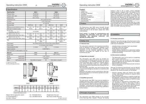
SW D B G DN T L<br />
DKM-2 27 31 52 1/2“ 15 14 90<br />
DKM-1<br />
34<br />
3/4“ 20 21 152<br />
40 76<br />
40<br />
1“ 25 17 130<br />
Overall dimensions mm<br />
DKM-1<br />
DKM-2<br />
Meister Strömungstechnik GmbH Tel. +49 6096 9720-0 info@<strong>meister</strong>-flow.com<br />
Im Gewerbegebiet 2 Fax +49 6096 9720-30 http://www.<strong>meister</strong>-flow.com<br />
DE-63831 Wiesen<br />
All rights reserved<br />
B DKM 0009 03-11 E M<br />
Content<br />
1 Preface ....................................... 1<br />
2 Safety hints ..................... 1<br />
3 Principle of operation ................. 1<br />
4 Installation ...................................... 1<br />
5 Electrical connection ................... 2<br />
6 Switch point adjustment ......... 3<br />
7 Maintenance ........................ 3<br />
8 Fault finding hints ........................... 3<br />
9 Specifications ............................... 4<br />
1 Preface<br />
The flowmonitors type DKM prove themself through<br />
reliability and simple handling. To use the advantages<br />
of the instrument to the full extent, please take notice<br />
of the following:<br />
Every person, in charge of commissioning and<br />
operating this instrument, must have read and<br />
understand this operating instruction and<br />
specially the safety hints!<br />
2 Safety hints<br />
2.1 General hints<br />
The instructions contained in the operating instructions<br />
must be followed to ensure a safe operation of the<br />
instrument. Further, the additional Legal- and safetyregulations<br />
for the individual application must be<br />
observed. Accordingly this applies for the use of<br />
accessories as well.<br />
2.2 Application as directed<br />
The instruments, type DKM, serve as monitors for<br />
continuous flow of viscous liquids. Any other use counts<br />
as nondirected. If not indicated otherwise, the scaling<br />
of the instruments refer to mineral oil. Special applications,<br />
where intermittent loads (e.a. cyclic operation)<br />
could occur, should be discussed and checked with our<br />
technical Staff.<br />
The instruments, type DKM, must not be used as single<br />
source to avoid dangerous situations on machinery and<br />
in plants.<br />
Machinery and plants must be constructed in that way,<br />
that faulty conditions do not lead the operators into dangerous<br />
situations.<br />
2.3 Qualified personnel<br />
The instruments, type DKM, must only be installed by<br />
qualified personnel, which is capable of using these instruments<br />
in a professional manner. Qualified personnel<br />
are such persons, which are familier with the erection,<br />
installation, commissioning and operation of these instruments<br />
and which hold a corresponding qualification<br />
for this function.<br />
3 Principle of operation<br />
The instruments type DKM operate on the principle<br />
of the float type flow indicator. Through the flowing<br />
medium a float is set in motion, whose integrated<br />
magnets create a magnetic field. The position of the<br />
float is detected with the switch contact. The float is<br />
reseted to the starting point by means of a spring, which<br />
allows the installation in any position in a system. The<br />
instruments are adjusted for the installation with flow<br />
from bottom to top. The weight of the float influences the<br />
measuring result, therefore a different mounting position<br />
will show discrepancies to the actual flow<br />
The instruments are viscosity compensated for a range<br />
from 30 to 600 cSt, this means, that occuring differences<br />
within this range, due to viscosity changes, will remain<br />
within the stated measuring tolerance.<br />
4 Installation<br />
4.1 Process connection<br />
Caution! To avoid the damage of the flowmonitor or the<br />
installation the following requirements must be fulfilled<br />
under any circumstances:<br />
- suitable process connection has to be provided<br />
- connection size to be checked<br />
- thread depth to be checked<br />
- suitable sealing material to be used (liquid sealing<br />
material will damage the flowmonitor if it gets inside)<br />
- professional sealing<br />
4.2 Enviroment conditions<br />
- The flowmonitor must not be used as a supporting<br />
part in a pipe construction.<br />
- The medium must not contain any solid particles.<br />
Magnetic particles will accumulate at the magnetic<br />
float and effect the function.<br />
- Before employment of anti-freeze and anti-corrosive<br />
check compatibility.<br />
Warning! The following requirements must be adhered<br />
to, otherwise the function of the flowmonitor will be<br />
affected or the measuring results will be falsified:<br />
- External magnetic fields will influence the switch<br />
contact. Keep sufficient distance to magnetic fields<br />
(e.a. Electricmotors).<br />
- Piping, process connections or supports made from<br />
ferromagnetic material influence the magnetic field<br />
of the flowmonitor. Keep a space of 100mm to those<br />
materials (e.a. steel).<br />
- The accuracy is influenced by cross-section changes,<br />
branches or elbows in the piping. Provide a<br />
straightening section of 10x DN upstream and 5x<br />
DN downstream of the instrument. Never reduce the<br />
pipe diameter direct ahead of the instrument!<br />
- With liquids ensure through suitable steps the deareation<br />
of the instrument.
Operating instruction DKM<br />
-2-<br />
<strong>meister</strong><br />
strömungstechnik<br />
gmbh<br />
Operating instruction DKM<br />
-3-<br />
<strong>meister</strong><br />
strömungstechnik<br />
gmbh<br />
5 Electrical connection<br />
The switch contacts are potential free and do not need<br />
any supply.<br />
Attention! Switch contact and unit are matched. After<br />
the exchange of a switch contact a readjustment must<br />
be made. Kindly request the relevant instruction.<br />
Switch position under No flow condition:<br />
2<br />
2<br />
3<br />
DIN 43650<br />
DIN 43650<br />
Connection: normally open<br />
1<br />
Connection: change over<br />
1<br />
5.1 Standard switch contact<br />
Pin-allocation of the supplied socket (DIN 43650 Form<br />
A or C). The Ground-pin is not used.<br />
Important instruction:<br />
When using the socket DIN 43650, the ingress protection<br />
IP65 is only warranted in connection with a<br />
suitable cablediameter.<br />
For infos on this subject please refer to page 4.<br />
5.2 Switch contact with cable<br />
The individual cores of the cable are marked according<br />
to the above connection diagram.<br />
4<br />
2<br />
4<br />
M 12x1<br />
M 12x1<br />
M 12x1<br />
1<br />
1<br />
The danger of overloads exist by means of:<br />
- inductive loads<br />
- capacitive loads<br />
- resistive loads<br />
Inductive load<br />
This kind of load will be caused by:<br />
- contactors, relais<br />
- solenoid valves<br />
- electricmotors<br />
Danger:<br />
Voltage peaks during switch off<br />
(up to 10-times of the nominal voltage)<br />
Precautionary measure: (sample)<br />
+<br />
V – D L<br />
-<br />
Capacitive load<br />
This kind of load will be caused by:<br />
-extrem long leads<br />
-capacitive consumption<br />
Danger:<br />
High current peaks during switch on of the switch<br />
contact<br />
(exceeding the nominal current)<br />
Precautionary measure: (sample)<br />
Limiting the current by means of a resistor<br />
Resistive load<br />
+<br />
V ~<br />
V –<br />
-<br />
+<br />
V ~<br />
V –<br />
-<br />
R<br />
R<br />
C<br />
C<br />
L<br />
Connection to SPS<br />
For the connection to high resistance devices (like SPS)<br />
a protection circuit is not necessary.<br />
6 Switchpoint adjustment<br />
- Loosen the lock screw of the switch contact<br />
- Shift the switch contact until the arrow on the switch<br />
contact is in coincidence with the desired switch<br />
point.<br />
- Tighten the look screw of the switch contact.<br />
Hints:<br />
- The adjusted switch point corresponds to the switch<br />
off point of the switch contact with decreasing flow.<br />
- The actual switch position can be checked by means<br />
of an universal tester.<br />
- The above description of the adjustment refers to the<br />
normally open contact.<br />
7 Maintenance<br />
Due to the few moving parts the instruments do not<br />
require much service.<br />
A functional check and service on a regular base will<br />
not only increase the lifetime and reliability of the<br />
instrument, but of the entire plant.<br />
The service intervals depend on<br />
- the pollution of the media<br />
- environmental conditions (e.a. vibrations)<br />
During maintenance at least the following points<br />
should be checked:<br />
- operation of the switch contact<br />
- leakage test of the instrument<br />
- free movement of the float<br />
It is the obligation of the user to lay down appropriate<br />
service intervals depending on the application.<br />
8 Fault finding hints<br />
The switch contact does not react:<br />
● The switch contact is permanent in break position<br />
╟ 1. No flow<br />
║<br />
╟<br />
║<br />
║<br />
║<br />
║<br />
► check for medium flow<br />
2. Flow to low or switch contact adjusted to<br />
high<br />
► Adjust switch point to a lower flow<br />
► Use instrument with different range<br />
╟ 3. Incorrect reduced (pipe diameter to small)<br />
║ ► reduce according to section 4<br />
╟ 4. Float got stuck (polluted)<br />
║<br />
║<br />
► Clean the instrument and ensure free movement<br />
of the float<br />
╙ 5. Switch contact faulty<br />
► Eliminate the reason for the fault (short<br />
circuit, overload)<br />
► Exchange switch contact, refer section 5<br />
● The switch contact is permanent in made position<br />
╟<br />
║<br />
║<br />
║<br />
║<br />
1. Flow to high and switch contact adjusted to<br />
low<br />
► Reduce flow<br />
► Adjust switch contact to a higher flow<br />
╟ 2. Float got stuck (polluted)<br />
║<br />
║<br />
► Clean the instrument and ensure free movement<br />
of the float<br />
╟ 3. Switch contact faulty<br />
║<br />
║<br />
╙<br />
► Eliminate the reason for the fault (short circuit,<br />
overload)<br />
► Exchange switch contact, refer section 5<br />
5.3 Special design<br />
On request special designed switch contacts (socket,<br />
ready-made cable) can be supplied.<br />
5.4 EEx-proof switch contacts<br />
Attention!<br />
For the connection of EEx-proof switch units special<br />
instructions apply, which must be followed! Pay attention<br />
to the hints in the separate operating instruction for<br />
EEx-proof switch contacts!<br />
5.5 Contact protection arrangement<br />
Attention!<br />
The following requirements must be adhered to under<br />
any circumstances, otherwise the switch contact will<br />
be destroyed!<br />
The reed-contacts employed in the switch contacts<br />
are, due to their construction, very fragile against over<br />
load. Non of the values voltage, current and wattage<br />
must be exceeded (Not even for a fractional moment).<br />
This kind of load will be caused by:<br />
- incandescent bulbs<br />
- Motor start up<br />
Danger:<br />
High current peaks during switch on of the switch contact,<br />
because the filament has low resistance at low<br />
temperatures.<br />
Precautionary measure: (sample)<br />
+<br />
V ~<br />
V –<br />
-<br />
R<br />
Limiting the current by means of a resistor or heating<br />
of the filament.<br />
+<br />
V ~<br />
V –<br />
-<br />
R<br />
Hints:<br />
- The free movement of the float and the operation of<br />
the switch contact can be checked by varying the<br />
flow and observing the switch contact status.<br />
- In most cases a purification can be achieved by flushing<br />
the instrument with clean media. In obstinate<br />
cases (e.a. calcareous deposits) cleaning can be<br />
done with commercial purifier, as long as the purifier<br />
is not aggressive against the material of the instrument.<br />
● Switch point does not match with actual flow<br />
╟ 1. No medium specific scale<br />
║<br />
║<br />
╟ 2. Incorrect reduced<br />
║ ► reduce according to section 4<br />
► Request a correction table or medium specific<br />
scale<br />
╟ 3. Instrument polluted<br />
║ ► clean the instrument<br />
╙ 4. Instrument defect<br />
► Return instrument for repair and calibration to<br />
manufacturer