Vogele Basic Training Hydraulics & Electrics
Vogele Basic Training Hydraulics & Electrics
Vogele Basic Training Hydraulics & Electrics

Create successful ePaper yourself
Turn your PDF publications into a flip-book with our unique Google optimized e-Paper software.
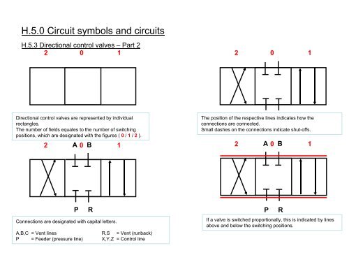
H.5.0 Circuit symbols and circuits<br />
H.5.3 Directional control valves – Part 2<br />
2 0 1 2 0 1<br />
Directional control valves are represented by individual<br />
rectangles.<br />
The number of fields equates to the number of switching<br />
positions, which are designated with the figures ( 0 / 1 / 2 ).<br />
A B<br />
2 0 1<br />
The position of the respective lines indicates how the<br />
connections are connected.<br />
Small dashes on the connections indicate shut-offs.<br />
A B<br />
2 0 1<br />
P R<br />
Connections are designated with capital letters.<br />
A,B,C = Vent lines<br />
R,S = Vent (runback)<br />
P = Feeder (pressure line) X,Y,Z = Control line<br />
P R<br />
If a valve is switched proportionally, this is indicated by lines<br />
above and below the switching positions.