SA 1940 Air Powered Rotary Hand Lancing Tool
SA 1940 Air Powered Rotary Hand Lancing Tool
SA 1940 Air Powered Rotary Hand Lancing Tool

Create successful ePaper yourself
Turn your PDF publications into a flip-book with our unique Google optimized e-Paper software.
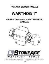
<strong>SA</strong> <strong>1940</strong> <strong>Air</strong> <strong>Powered</strong> <strong>Rotary</strong> <strong>Hand</strong> <strong>Lancing</strong> <strong>Tool</strong><br />
Description:<br />
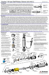
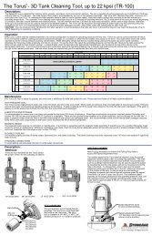
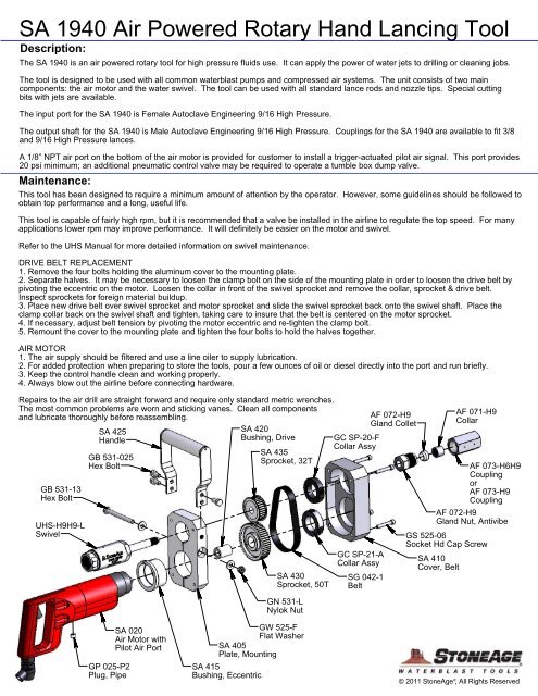
The <strong>SA</strong> <strong>1940</strong> is an air powered rotary tool for high pressure fluids use. It can apply the power of water jets to drilling or cleaning jobs.<br />
The tool is designed to be used with all common waterblast pumps and compressed air systems. The unit consists of two main<br />
components: the air motor and the water swivel. The tool can be used with all standard lance rods and nozzle tips. Special cutting<br />
bits with jets are available.<br />
The input port for the <strong>SA</strong> <strong>1940</strong> is Female Autoclave Engineering 9/16 High Pressure.<br />
The output shaft for the <strong>SA</strong> <strong>1940</strong> is Male Autoclave Engineering 9/16 High Pressure. Couplings for the <strong>SA</strong> <strong>1940</strong> are available to fit 3/8<br />
and 9/16 High Pressure lances.<br />
A 1/8” NPT air port on the bottom of the air motor is provided for customer to install a trigger-actuated pilot air signal. This port provides<br />
20 psi minimum; an additional pneumatic control valve may be required to operate a tumble box dump valve.<br />
Maintenance:<br />
This tool has been designed to require a minimum amount of attention by the operator. However, some guidelines should be followed to<br />
obtain top performance and a long, useful life.<br />
This tool is capable of fairly high rpm, but it is recommended that a valve be installed in the airline to regulate the top speed. For many<br />
applications lower rpm may improve performance. It will definitely be easier on the motor and swivel.<br />
Refer to the UHS Manual for more detailed information on swivel maintenance.<br />
DRIVE BELT REPLACEMENT<br />
1. Remove the four bolts holding the aluminum cover to the mounting plate.<br />
2. Separate halves. It may be necessary to loosen the clamp bolt on the side of the mounting plate in order to loosen the drive belt by<br />
pivoting the eccentric on the motor. Loosen the collar in front of the swivel sprocket and remove the collar, sprocket & drive belt.<br />
Inspect sprockets for foreign material buildup.<br />
3. Place new drive belt over swivel sprocket and motor sprocket and slide the swivel sprocket back onto the swivel shaft. Place the<br />
clamp collar back on the swivel shaft and tighten, taking care to insure that the belt is centered on the motor sprocket.<br />
4. If necessary, adjust belt tension by pivoting the motor eccentric and re-tighten the clamp bolt.<br />
5. Remount the cover to the mounting plate and tighten the four bolts to hold the halves together.<br />
AIR MOTOR<br />
1. The air supply should be filtered and use a line oiler to supply lubrication.<br />
2. For added protection when preparing to store the tools, pour a few ounces of oil or diesel directly into the port and run briefly.<br />
3. Keep the control handle clean and working properly.<br />
4. Always blow out the airline before connecting hardware.<br />
Repairs to the air drill are straight forward and require only standard metric wrenches.<br />
The most common problems are worn and sticking vanes. Clean all components<br />
and lubricate thoroughly before reassembling.<br />
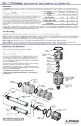
GB 531-13<br />
Hex Bolt<br />
UHS-H9H9-L<br />
Swivel<br />
<strong>SA</strong> 425<br />
<strong>Hand</strong>le<br />
GB 531-025<br />
Hex Bolt<br />
<strong>SA</strong> 420<br />
Bushing, Drive<br />
<strong>SA</strong> 435<br />
Sprocket, 32T<br />
<strong>SA</strong> 430<br />
Sprocket, 50T<br />
GN 531-L<br />
Nylok Nut<br />
GC SP-20-F<br />
Collar Assy<br />
GC SP-21-A<br />
Collar Assy<br />
SG 042-1<br />
Belt<br />
AF 072-H9<br />
Gland Collet<br />
AF 072-H9<br />
Gland Nut, Antivibe<br />
<strong>SA</strong> 410<br />
Cover, Belt<br />
AF 071-H9<br />
Collar<br />
GS 525-06<br />
Socket Hd Cap Screw<br />
AF 073-H6H9<br />
Coupling<br />
or<br />
AF 073-H9<br />
Coupling<br />
GP 025-P2<br />
Plug, Pipe<br />
<strong>SA</strong> 020<br />
<strong>Air</strong> Motor with<br />
Pilot <strong>Air</strong> Port<br />
GW 525-F<br />
Flat Washer<br />
<strong>SA</strong> 405<br />
Plate, Mounting<br />
<strong>SA</strong> 415<br />
Bushing, Eccentric<br />
®<br />
© 2011 StoneAge , All Rights Reserved
Form A223C<br />
Date 6-00/B<br />
Page 1 of 2<br />
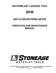
PARTS LIST FOR<br />
1464, 1465, 1465-1/2, 1466, & 1467 AIR DRILL<br />
(SERIAL 11221 UP TO B)<br />
(SERIAL B100 & UP)<br />
1<br />
Printed In U.S.A.
PARTS LIST FOR<br />
1464, 1465, 1465-1/2, 1466, & 1467 AIR DRILL<br />
(SERIAL 11221 UP TO B)<br />
(SERIAL B100 & UP)<br />
Fig. Part<br />
No. No. Description<br />
1. 30011 Key-Chuck<br />
2. 21002 Chuck-3/8" Capacity (1465)<br />
21137 Chuck-1/2" Capacity (1464, 1465-1/2, 1466,<br />
1467)<br />
3. 44493 Retainer<br />
4. 10198 Bearing-Ball<br />
5. 44494 Support-Spindle<br />
6. 43327 Ass’y-Planetary Gear (1465, 1466,1467)<br />
63583 Ass’y-Planetary Gear (1464)<br />
7. 19197 Gear-Ring<br />
8. 35128 Washer<br />
9. 35134 Washer<br />
10. 30467 Pin<br />
11. 63349 Ass’y-Side <strong>Hand</strong>le<br />
12. 12299 Case-Gear<br />
13. 30356 Fitting-Grease<br />
14. 10042 Bearing-Needle<br />
15. 19461 Gear & Pinion (1465)<br />
19462 Gear & Pinion (i466, 1467)<br />
19493 Gear & Pinion (1464)<br />
16. 21531 Ring-Lock<br />
17. 19324 Ass’y-Gear & Bearing (2)*(1465, 1466, 1467)<br />
19325 Ass’y-Gear & Bearing (2)*(1464)<br />
18. 10028 Bearing-Needle (4)*<br />
19. 22640 Spindle-Chuck (1465, 1466, 1467)<br />
64184 Spindle-Chuck (1464)<br />
20. 21524 Ring-Retaining (Used on Some Models)<br />
21753 Ring-Retaining (1464)<br />
21. 10044 Bearing-Needle<br />
22. 10203 Bearing-Ball<br />
23. 25976 Washer<br />
24. 43133 Ass’y-Swivel<br />
25. 21523 Ring-Retaining<br />
26. 13201 Swivel<br />
27. 34819 Pin<br />
28. 43334 Ass’y-Swivel Body<br />
29. 14312 Ring-”O” (3)*<br />
30. 33998 Ass’y-Throttle Valve<br />
31. 33993 Ass’y-<strong>Air</strong> Screen<br />
32. 14307 Ring-”O”<br />
33. 14274 Ring-”O”<br />
34. 30424 Pin<br />
35. 30375 Fitting-Grease<br />
36. 30347 Pin (2)*<br />
37. 33967 Ass’y-Trigger<br />
Fig. Part<br />
No. No. Description<br />
38. 07129 Screw (4)*<br />
39. Q9724 Washer-Lock (4)*<br />
40. 43073 Ass’y-<strong>Hand</strong>le (Incl. Fig. 24-37, 41-45, 55, 56)<br />
41. 44253 Oiler Screw & “O” Ring<br />
42. 14369 Ring-”O”<br />
43. 43664 Ass’y-Governor Valve<br />
44. 09704 Washer-Lock (2)*<br />
45. 06325 Screw (2)*<br />
46. 35067 Washer-Wave<br />
47. 10520 End Plate-Rear<br />
48. 33997 Vane-Rotor (Set of 4)<br />
49. 12276 Housing<br />
50. 33979 Cylinder<br />
51. 10521 Plate-Front End (Up to Ser. No. B)<br />
10531 Plate-Front End (Ser. No. B -100 & up)<br />
52. 10203 Bearing-Ball (Up to Ser. No. B)<br />
10228 Bearing-Ball (Ser. No. B -100 & up)<br />
53. 44219 Key-Rotor<br />
54. 22641 Spindle-Rotor (1464, 1465)<br />
22642 Spindle-Rotor (1466, 1467)<br />
55. 14750 Retainer-Screw (2)*<br />
56. 44245 Retainer-Governor Valve<br />
57. 14751 Gasket<br />
58. 43672 Ass’y-Governor (1464, 1465, & 1466)<br />
43670 Ass’y-Governor (1467)<br />
59. 10241 Bearing-Ball<br />
60. 44220 Rotor<br />
61. 06000 Screw (2)*<br />
62. 20368R Plate-Name<br />
63. 44379 Spacer-Governor (1465, 1466, 1464)(4)*<br />
44218 Spacer-Governor (1467)(4)*<br />
64. 30336 Pin-Roll (2)*<br />
65. 21411 Spring-Governor (Red)(1465, 1466, 1464)<br />
21416 Spring-Governor (Green)(1467)<br />
66. 13183 Nut-Governor Adjusting<br />
67. 35069 Weight-Governor (1465, 1464,<br />
1466)(4)*(1467)(6)*<br />
68. 43666 Ass’y-Bearing Support & Spindle<br />
69. 44222 Frame-Governor<br />
70. 19206 Gear-Pinion (1464)<br />
71. 30467 Pin (1465, 1466, 1467)(2)*<br />
30369 Pin (1464)(2)*<br />
72. 35260 Washer (1464)<br />
*Order Quantity As Required<br />
FURNISH CATALOG, SERIAL, AND MODEL NUMBER WHEN<br />
ORDERING PARTS<br />
2<br />
Printed In U.S.A.
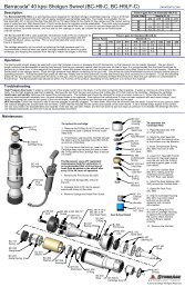
40 kpsi UHS Swivel (UHS-H9H9, UHS-H9H9-L)<br />
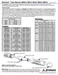
Description:<br />
The UHS swivel was designed to convey high pressure water from a stationary<br />
line to a powered rotating or twisting assembly. It is typically used on lancing<br />
machines, surface cleaning machines, and hose reels. The swivel requires a<br />
torque of 15 to 50 in-lb to overcome the rotational drag of the high pressure seal<br />
while operating at working pressure.<br />
The UHS swivel is rated for 40,000 psi (2800 bar) working pressure, and a<br />
maximum rotation speed of 1500 rpm. It has a flow capacity rating of Cv = .3.<br />
To determine pressure loss thru the swivel at a given flow, divide the flow by<br />
the Cv and square the result. This is the pressure drop in psi.<br />
Maximum Operating Pressure<br />
Inlet Connection<br />
Rotation Speed, Max<br />
Shaft Connection<br />
Torque Required<br />
Flow Rating<br />
40,000 (2800 bar)<br />
9/16 HP<br />
1,500 rpm<br />
9/16 HP<br />
15 - 50 in-lb<br />
0.3 Cv<br />
A single high pressure seal is used to provide leak free operation. The seal life will vary depending on the rotation speed. Higher rotation<br />
speeds result in shorter seal life. The high pressure seal is considered a wear item, and can be replaced easily and inexpensively.<br />
The UHS swivel has a 9/16 High Pressure Autoclave female inlet connection, and the outlet has a 9/16 High Pressure Autoclave LH male<br />
shaft connection.<br />
Operation:<br />
If the swivel will be used at rotation speeds above 500 rpm, the swivel should be allowed a 1/2 hour break-in period where the swivel is<br />
run at operating pressure, but with a maximum rotation speed of 500 rpm. The swivel should never be rotated without water passing thru.<br />
Use anti-seize on all threaded connections to prevent galling. Grease the swivel whenever the H.P Seal needs replacement, depending on<br />
rotation speed and service conditions.<br />
Troubleshooting:<br />
Seal Leak: the swivel seal may intermittently leak a little bit. If the leak becomes continuous at operating pressure, the high pressure seal<br />
should be replaced.<br />
Seals wear out quickly: inspect the portion of the shaft that passes through the bronze backup. If it appears galled, or the inside of the<br />
backup is galled, the shaft needs to be lightly polished to remove the bronze buildup (but not polished enough to remove the coating) and<br />
the bronze backup needs to be replaced. If seals are wearing quickly but the above has not happened, the bronze backup is worn oversize<br />
and needs to be replaced.<br />
Maintenance:<br />
*Blow out all water with compressed air before storing tool!<br />
UHS 002-H9<br />
Inlet Nut<br />
High Pressure Seal Maintenance:<br />
1. Unscrew the Inlet Nut from the Body.<br />
2. The H.P. Seal will likely stay inside the Inlet Nut.<br />
3. Use a 3/16 nail head or 10-24 screw to pull the<br />
H.P. Seal out of the Inlet Nut.<br />
4. Apply grease to the outside of a new H.P. Seal, and<br />
apply grease to the shaft end where the seal will sit.<br />
5. Push the H.P. Seal into the Inlet Nut, just until flush<br />
with face of nut. The chamfered end should face out.<br />
6. Carefully insert the Inlet Nut with H.P. Seal over the<br />
end of the shaft and screw it into the body. Tighten to<br />
40 ft-lbs.<br />
3/16 nail head<br />
or 10-24 screw<br />
chamfered end<br />
UHS 012-TO<br />
H.P. Seal<br />
& O-Ring<br />
UHS 002-H9<br />
Inlet Nut<br />
UHS 002-H9<br />
Inlet Nut<br />
UHS 012-TO<br />
H.P. Seal & O-Ring<br />
UHS 004<br />
Backup<br />
RJ 008<br />
O-Ring<br />
RJ 029<br />
Shaft Seal<br />
RJ 009<br />
Bearing<br />
UHS 001<br />
Shaft<br />
UHS 001-L<br />
Shaft, Long<br />
UHS 005<br />
Ring, Spacer<br />
RJ 007<br />
Bearing (2)<br />
UHS 003<br />
Body<br />
AF 072-H9<br />
Antivibe Gland<br />
AF 071-H9<br />
Collar<br />
RJ 029<br />
Shaft Seal<br />
®<br />
© 2010 StoneAge , All Rights Reserved
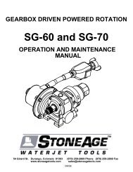
40 kpsi UHS Swivel (UHS-H9H9, UHS-H9H9-L)<br />
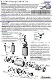
Disassembly:<br />
UHS 002-H9<br />
Inlet Nut<br />
1. Remove the Inlet Nut (UHS 004-H9)<br />
from the Body (UHS 003). The High<br />
Pressure Seal (UHS 012-TO) will likely<br />
stay inside the Inlet Nut.<br />
2. Remove the Collar (AF 071-H9) and<br />
the Antivibe Gland (AF 072-H9) from the<br />
Shaft.<br />
3. Use a 3/16 nail head or 10-24 screw<br />
to hook the back side of the H.P. Seal<br />
and pull the H.P. Seal out of the Inlet<br />
Nut.<br />
3/16 nail head<br />
or 10-24 screw<br />
UHS 012-TO<br />
H.P. Seal & O-Ring<br />
4. Push the Shaft (UHS 001 or 001-L)<br />
out of the Body. The bearings should<br />
come out with the shaft.<br />
5. Remove the Backup (UHS 004) from<br />
the Shaft.<br />
5. Press the bearings (RJ 009 & 2x RJ<br />
007) and the Spacer Ring (UHS 005)<br />
off of the Shaft. Be careful not to<br />
damage the coated surface of the shaft<br />
(the smaller diameter shiny portion).<br />
6. Inspect the coated portion of the<br />
shaft for wear or grooving. Replace if<br />
badly grooved.<br />
7. Inspect the Shaft Seals (RJ 029) in<br />
the Backup and the Body for damage.<br />
Remove them only if they need<br />
replacing.<br />
8. Inspect the O-Ring (RJ 008) in the<br />
groove on the outside of the Backup.<br />
Remove if it is damaged.<br />
UHS 004<br />
Backup<br />
RJ 008<br />
O-Ring<br />
RJ 029<br />
Shaft Seal<br />
RJ 009<br />
Bearing<br />
UHS 003<br />
Body<br />
UHS 002-H9<br />
Inlet Nut<br />
Shaft w/ bearings<br />
UHS 001<br />
Shaft<br />
UHS 001-L<br />
Shaft. Long<br />
RJ 029<br />
Shaft Seal<br />
UHS 005<br />
Spacer Ring<br />
AF 072-H9<br />
Antivibe Gland<br />
UHS 003<br />
Body<br />
RJ 007<br />
Bearings<br />
AF 071-H9<br />
Collar<br />
Assembly:<br />
1. Install Shaft Seal (RJ 029) into the Body.<br />
Note the lip with the spring goes in last.<br />
Grease the lips of the Seal.<br />
2. Install Shaft Seal (RJ 029) into the<br />
Backup. Note the lip with the spring goes in<br />
first. Grease the lips of the Seal.<br />
3. Place the O-Ring (RJ 008) into the groove<br />
on the outside of the Backup. Grease the<br />
outside of the O-Ring.<br />
UHS 003<br />
Body<br />
4. Prior to installation, pack bearings<br />
liberally with grease on both sides.<br />
5. Install Bearings (RJ 009 & 2x RJ<br />
007) and Spacer (UHS 005) onto Shaft<br />
(UHS 001 or 001-L). Note that the two<br />
lower bearings (RJ 007) must be<br />
installed with the wide inner race in the<br />
correct direction.<br />
6. Carefully slide the Backup onto the<br />
Shaft with the Shaft Seal towards the<br />
bearings.<br />
7. Gently slide the Shaft assembly with Bearings<br />
into the Body.<br />
8. Apply grease to the outside of the H.P. Seal and<br />
press into the Inlet Nut, just until flush with face of<br />
nut. The chamfered end should face out.<br />
9. Apply grease to the seal surface of the shaft<br />
(small diameter).<br />
10. Apply antisieze to the threads on the Inlet Nut.<br />
Carefully insert the Inlet Nut with H.P. Seal over the<br />
end of shaft and screw it into the Body. Tighten to<br />
40 ft-lbs.<br />
UHS 002-H9<br />
Inlet Nut<br />
RJ 009<br />
Bearing<br />
11. Slide Antivibe Gland (AF 072-H9) onto shaft,<br />
and screw the Collar (AF 071-H9) on until shaft<br />
threads are just visible past the cone of the shaft.<br />
UHS 012-TO<br />
H.P. Seal<br />
chamfered end<br />
UHS 002-H9<br />
Inlet Nut<br />
RJ 029<br />
Shaft Seal<br />
lip with spring<br />
UHS 001<br />
Shaft<br />
UHS 001-L<br />
Shaft, Long<br />
RJ 029<br />
Shaft Seal<br />
UHS 005<br />
Spacer Ring<br />
Shaft w/ bearings<br />
AF 072-H9<br />
Antivibe Gland<br />
lip with spring<br />
wide inner race<br />
RJ 008<br />
O-Ring<br />
UHS 004<br />
Backup<br />
wide inner race<br />
Body<br />
AF 071<br />
Collar<br />
wide inner race<br />
RJ 007<br />
Bearings<br />
wide outer race<br />
RJ 007 Bearing Detail<br />
®<br />
© 2010 StoneAge , All Rights Reserved