Aruba Mobility Controllers and Deployment Models ... - Mayflex
Aruba Mobility Controllers and Deployment Models ... - Mayflex
Aruba Mobility Controllers and Deployment Models ... - Mayflex

Create successful ePaper yourself
Turn your PDF publications into a flip-book with our unique Google optimized e-Paper software.
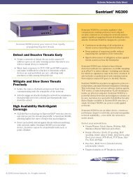
<strong>Aruba</strong> <strong>Mobility</strong> <strong>Controllers</strong><br />
<strong>and</strong> <strong>Deployment</strong> <strong>Models</strong><br />
Validated Reference Design<br />
Version 5.0<br />
Solution Guide
Copyright<br />
© 2010 <strong>Aruba</strong> Networks, Inc. AirWave®, <strong>Aruba</strong> Networks®, <strong>Aruba</strong> <strong>Mobility</strong> Management System®, Bluescanner, For Wireless That<br />
Works®, Mobile Edge Architecture®, People Move. Networks Must Follow®, RFprotect®, The All Wireless Workplace Is Now Open For<br />
Business, Green Isl<strong>and</strong>, <strong>and</strong> The Mobile Edge Company® are trademarks of <strong>Aruba</strong> Networks, Inc. All rights reserved. <strong>Aruba</strong> Networks<br />
reserves the right to change, modify, transfer, or otherwise revise this publication <strong>and</strong> the product specifications without notice. While<br />
<strong>Aruba</strong> uses commercially reasonable efforts to ensure the accuracy of the specifications contained in this document, <strong>Aruba</strong> will assume<br />
no responsibility for any errors or omissions.<br />
Open Source Code<br />
Certain <strong>Aruba</strong> products include Open Source software code developed by third parties, including software code subject to the GNU<br />
General Public License (“GPL”), GNU Lesser General Public License (“LGPL”), or other Open Source Licenses. The Open Source code<br />
used can be found at this site:<br />
http://www.arubanetworks.com/open_source<br />
Legal Notice<br />
ARUBA DISCLAIMS ANY AND ALL OTHER REPRESENTATIONS AND WARRANTIES, WEATHER EXPRESS, IMPLIED, OR<br />
STATUTORY, INCLUDING WARRANTIES OF MERCHANTABILITY, FITNESS FOR A PARTICULAR PURPOSE, TITLE,<br />
NONINFRINGEMENT, ACCURACY AND QUET ENJOYMENT. IN NO EVENT SHALL THE AGGREGATE LIABILITY OF ARUBA EXCEED<br />
THE AMOUNTS ACUTALLY PAID TO ARUBA UNDER ANY APPLICABLE WRITTEN AGREEMENT OR FOR ARUBA PRODUCTS OR<br />
SERVICES PURSHASED DIRECTLY FROM ARUBA, WHICHEVER IS LESS.<br />
www.arubanetworks.com<br />
1344 Crossman Avenue<br />
Sunnyvale, California 94089<br />
Phone: 408.227.4500<br />
Fax 408.227.4550<br />
<strong>Aruba</strong> <strong>Mobility</strong> <strong>Controllers</strong> <strong>and</strong> <strong>Deployment</strong> <strong>Models</strong> VRD | Solution Guide August 2010
Contents<br />
Chapter 1 Introduction 7<br />
<strong>Aruba</strong> Reference Architectures 7<br />
Reference Documents 7<br />
Chapter 2 Summary of Recommendations 9<br />
Campus <strong>Deployment</strong>s 9<br />
Remote <strong>Deployment</strong>s 11<br />
Branch Offices 13<br />
Small Offices with Single Sites 15<br />
Chapter 3 Underst<strong>and</strong>ing the <strong>Aruba</strong> <strong>Mobility</strong> Controller <strong>and</strong> AWMS 17<br />
Controller Overview 19<br />
<strong>Aruba</strong> 6000 Chassis <strong>and</strong> M3 Blade 19<br />
<strong>Aruba</strong> 3000 Series 19<br />
600 Series 20<br />
Next Steps 20<br />
Underst<strong>and</strong>ing <strong>Mobility</strong> Controller Master/Local Model 20<br />
Underst<strong>and</strong>ing the Master <strong>Mobility</strong> Controller 21<br />
Underst<strong>and</strong>ing the Local <strong>Mobility</strong> Controller 23<br />
Underst<strong>and</strong>ing the Role of the AirWave Wireless Management Suite 26<br />
<strong>Mobility</strong> Controller <strong>Deployment</strong> Options 28<br />
Campus <strong>Deployment</strong>s 28<br />
St<strong>and</strong>-Alone <strong>Mobility</strong> Controller Operation 29<br />
Branch Office Controller 30<br />
RAP <strong>and</strong> IPsec Gateway 31<br />
Wired Gateway 32<br />
All Masters with AWMS 33<br />
Distributed All Masters 33<br />
Campus All Masters 34<br />
Chapter 4 Controller Licensing 35<br />
License Descriptions 35<br />
Underst<strong>and</strong>ing the Functionality of PEF-NG <strong>and</strong> PEFV 36<br />
Licensing Requirements <strong>and</strong> Recommendations 36<br />
Matching AP-Based Licenses 36<br />
Master <strong>Mobility</strong> Controller Licensing Requirements 37<br />
Local <strong>Mobility</strong> Controller Licensing Requirements 37<br />
Chapter 5 AP Forwarding Modes 39<br />
Campus <strong>Deployment</strong>s 40<br />
Tunnel Mode 40<br />
Decrypt-Tunnel Mode 41<br />
Bridge Mode 42<br />
Forwarding Mode Client Limits 43<br />
Campus Forwarding Mode Recommendations 43<br />
<strong>Aruba</strong> <strong>Mobility</strong> <strong>Controllers</strong> <strong>and</strong> <strong>Deployment</strong> <strong>Models</strong> VRD | Solution Guide Contents | 3
RAP <strong>Deployment</strong>s 44<br />
Tunnel Mode 44<br />
Decrypt-Tunnel Mode 45<br />
Bridge Mode 46<br />
Policy-based Forwarding (Split-tunnel) Mode 47<br />
Remote Forwarding Mode Recommendations 48<br />
Control Plane Security 48<br />
IPsec Connections <strong>and</strong> Certificates 49<br />
Campus AP White List 51<br />
AP <strong>and</strong> Controller Tunnels 52<br />
Trust Anchors 53<br />
Considerations in CPsec <strong>Deployment</strong>s 54<br />
Chapter 6 Physical <strong>Deployment</strong> Considerations 55<br />
<strong>Mobility</strong> Controller <strong>Deployment</strong>s 56<br />
Data Center 56<br />
Core 57<br />
Distribution Layer 57<br />
Access Layer 58<br />
DMZ 59<br />
AirWave <strong>Deployment</strong>s 60<br />
Local Data Center 60<br />
Remote Data Center 60<br />
Physical <strong>Deployment</strong> Considerations <strong>and</strong> Recommendations 60<br />
Considerations for Local <strong>Mobility</strong> Controller Physical <strong>Deployment</strong>s 60<br />
Physical <strong>Deployment</strong> Recommendation 61<br />
Chapter 7 Regulatory Compliance for International <strong>Deployment</strong>s 63<br />
Controller Compliance 63<br />
Recommendations for International <strong>Deployment</strong>s 64<br />
Chapter 8 Logical <strong>Deployment</strong> Considerations 65<br />
User VLANs 66<br />
User VLANs in Tunnel <strong>and</strong> Decrypt-Tunnel Modes 66<br />
User VLANs in CAP Bridge Mode 68<br />
User VLANs in Remote AP Bridge Mode 68<br />
User VLANs in Split-Tunnel Mode 69<br />
Guest VLANs 70<br />
Dedicated AP VLANs 73<br />
Quarantine VLANs 75<br />
VLAN Pools 77<br />
Packet Sizing 79<br />
Default Gateways <strong>and</strong> Routes 79<br />
Layer 2 <strong>Deployment</strong>s 79<br />
Layer 3 <strong>Deployment</strong>s 80<br />
Static Routes <strong>and</strong> OSPF 81<br />
Logical Design Recommendations 82<br />
Campus Logical Design Recommendations 82<br />
Chapter 9 <strong>Mobility</strong> 85<br />
Layer 2 <strong>Mobility</strong> (VLAN <strong>Mobility</strong>) 85<br />
Roaming Between APs in Bridge Mode 86<br />
Layer 3 <strong>Mobility</strong> (Mobile IP) 87<br />
<strong>Mobility</strong> Domains 87<br />
4 | Contents <strong>Aruba</strong> <strong>Mobility</strong> <strong>Controllers</strong> <strong>and</strong> <strong>Deployment</strong> <strong>Models</strong> VRD | Solution Guide
<strong>Mobility</strong> Recommendations 89<br />
Chapter 10 Redundancy <strong>Models</strong> 91<br />
Master Redundancy 92<br />
Local Redundancy 93<br />
Active-Active (1:1) 93<br />
Active-St<strong>and</strong>by (1+1) 95<br />
Many-to-One (N+1) 96<br />
Comparison of Local Redundancy <strong>Models</strong> 98<br />
AirWave Redundancy 99<br />
Data Center Redundancy 100<br />
No Redundancy 103<br />
Master <strong>Mobility</strong> Controller – No Redundancy 103<br />
Local <strong>Mobility</strong> Controller – No Redundancy 105<br />
AWMS – No Redundancy 105<br />
Data Center – No Redundancy 105<br />
<strong>Aruba</strong> Recommendations for Redundancy 105<br />
Chapter 11 <strong>Mobility</strong> Controller Selection 107<br />
Information Gathering 107<br />
Controller Selection Formula – Local <strong>Controllers</strong> 108<br />
Controller Scalability Table 108<br />
Local <strong>Mobility</strong> Controller – Campus or Branch <strong>Deployment</strong> 109<br />
Local <strong>Mobility</strong> Controller - Remote Access Point <strong>Deployment</strong> 110<br />
Local <strong>Mobility</strong> Controller - VIA <strong>Deployment</strong>s 111<br />
Calculating RAP <strong>and</strong> VIA Clients on the Same <strong>Mobility</strong> Controller 111<br />
Controller Selection Formula – Master <strong>Mobility</strong> Controller 112<br />
Redundancy Considerations for Controller Count 112<br />
When to Consider a <strong>Mobility</strong> Controller Upgrade 112<br />
<strong>Mobility</strong> Controller 113<br />
AWMS 115<br />
Chapter 12 Putting It All Together 117<br />
Appendix A CPsec Scalability 119<br />
Appendix B AP Failover Times 121<br />
Appendix C Scalability in the All Masters <strong>Deployment</strong> Model 123<br />
Contents<br />
9<br />
Appendix D <strong>Aruba</strong> Contact Information 125<br />
Contacting <strong>Aruba</strong> Networks 125<br />
<strong>Aruba</strong> <strong>Mobility</strong> <strong>Controllers</strong> <strong>and</strong> <strong>Deployment</strong> <strong>Models</strong> VRD | Solution Guide Contents | 5
6 | Contents <strong>Aruba</strong> <strong>Mobility</strong> <strong>Controllers</strong> <strong>and</strong> <strong>Deployment</strong> <strong>Models</strong> VRD | Solution Guide
Chapter 1<br />
Introduction<br />
<strong>Aruba</strong> Reference Architectures<br />
The <strong>Aruba</strong> Validated Reference Design (VRD) series is a collection of technology deployment guides<br />
that include descriptions of <strong>Aruba</strong> technology, recommendations for product selections, network<br />
design decisions, configuration procedures, <strong>and</strong> best practices for deployment. Together these guides<br />
comprise a reference model for common customer deployment scenarios. Each <strong>Aruba</strong> VRD network<br />
design has been constructed in a lab environment <strong>and</strong> thoroughly tested by <strong>Aruba</strong> engineers. Our<br />
customers use these proven designs to rapidly deploy <strong>Aruba</strong> solutions in production with the assurance<br />
that they will perform <strong>and</strong> scale as expected.<br />
The VRD in this guide discusses deployment models <strong>and</strong> mobility controller selection. This guide<br />
describes:<br />
• Operating modes for the mobility controller<br />
• Licensing<br />
• Forwarding modes<br />
• Logical <strong>and</strong> physical deployment<br />
• Redundancy<br />
• How to select the appropriate mobility controller based on scalability requirements<br />
This guide will help you underst<strong>and</strong> the capabilities <strong>and</strong> options you have when deploying an <strong>Aruba</strong><br />
<strong>Mobility</strong> Controller. Other guides in the series will build specific deployments using the information in<br />
this guide.<br />
Reference Documents<br />
This VRD is the first in a series of new guides in a revised format, <strong>and</strong> it is intended to provide the most<br />
current information about the mobility controller technology <strong>and</strong> deployment models introduced in<br />
<strong>Aruba</strong>OS 5.0. Other guides in the series will cover 802.11n <strong>and</strong> AP deployments, user roles <strong>and</strong> firewall<br />
policies, outdoor deployments, <strong>and</strong> configurations for specific deployments such as campus or remote<br />
networks. This guide is a foundation-level guide, <strong>and</strong> therefore it will not cover the configuration of the<br />
<strong>Aruba</strong> system. Instead, it is intended to provide the baseline knowledge that a wireless engineer must<br />
use to deploy an architecture that is based on the mobility controller.<br />
For specific deployment configuration details, see the 3.X series of VRDs on the <strong>Aruba</strong> website at<br />
http://www.arubanetworks.com/vrd. The existing VRDs will be updated to follow this new format.<br />
The complete suite of <strong>Aruba</strong> technical documentation is available for download from the <strong>Aruba</strong> support<br />
site. These documents present complete, detailed feature <strong>and</strong> functionality explanations beyond the<br />
scope of the VRD series. The <strong>Aruba</strong> support site is located at:<br />
https://support.arubanetworks.com/.<br />
For more training on <strong>Aruba</strong> products or to learn about <strong>Aruba</strong> certifications, visit our training <strong>and</strong><br />
certification page on our public website. This page contains links to class descriptions, calendars, <strong>and</strong><br />
test descriptions: http://www.arubanetworks.com/training.php<br />
<strong>Aruba</strong> hosts a user forum site <strong>and</strong> user meetings called Airheads. The forum contains discussions of<br />
deployments, products, <strong>and</strong> troubleshooting tips. Airheads is an invaluable resource that allows<br />
<strong>Aruba</strong> <strong>Mobility</strong> <strong>Controllers</strong> <strong>and</strong> <strong>Deployment</strong> <strong>Models</strong> VRD | Solution Guide Introduction | 7
network administrators to interact with each other <strong>and</strong> <strong>Aruba</strong> experts. Announcements for Airheads<br />
meetings are also available on the site: http://airheads.arubanetworks.com/<br />
The VRD series assumes a working knowledge of Wi-Fi®, <strong>and</strong> more specifically dependent AP-based<br />
architectures. For more information about wireless technology fundamentals, visit the Certified<br />
Wireless Network Professional (CWNP) site at http://www.cwnp.com<br />
8 | Introduction <strong>Aruba</strong> <strong>Mobility</strong> <strong>Controllers</strong> <strong>and</strong> <strong>Deployment</strong> <strong>Models</strong> VRD | Solution Guide
Chapter 2<br />
Summary of<br />
Recommendations<br />
This VRD explains the recommendations that <strong>Aruba</strong> provides for deploying a scalable, mobility<br />
controller-based wireless LAN (WLAN) system. The details of the system occasionally require lengthy<br />
explanations <strong>and</strong> diagrams to sufficiently convey the details of the solution. This section provides an<br />
overview of the <strong>Aruba</strong> recommendations for mobility controller deployments, which are explained in<br />
detail in the following sections.<br />
Campus <strong>Deployment</strong>s<br />
Campus-based deployments are networks that require more than a single controller to cover a<br />
contiguous space. Examples of campus-based deployments are corporate campuses, large hospitals,<br />
<strong>and</strong> higher-education campuses. In these deployments, the WLAN is often the primary access method<br />
for the network, <strong>and</strong> it is typically used by multiple classes of users <strong>and</strong> devices.<br />
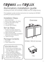
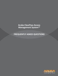
Figure 1 Typical campus deployment with redundancy<br />
Data Center<br />
AWMS<br />
Server<br />
Master<br />
active<br />
Master<br />
st<strong>and</strong>by<br />
POS<br />
File<br />
PBX<br />
RADIUS<br />
Internet<br />
Local<br />
<strong>Mobility</strong> Controller<br />
Local<br />
<strong>Mobility</strong><br />
Controller<br />
Air Monitor<br />
arun_0279<br />
<strong>Aruba</strong> <strong>Mobility</strong> <strong>Controllers</strong> <strong>and</strong> <strong>Deployment</strong> <strong>Models</strong> VRD | Solution Guide Summary of Recommendations | 9
The following table summarizes the recommendations for campus-based deployments.<br />
Table 1 Campus <strong>Deployment</strong> Recommendations<br />
Feature or Function<br />
Master/local or all masters<br />
Physical location of the master mobility<br />
controller<br />
Master mobility controller redundancy<br />
Physical location of the local mobility<br />
controller<br />
Local mobility controller redundancy<br />
Local mobility controller load<br />
Control plane security (CPsec)<br />
AirWave Wireless Management Suite<br />
(AWMS)<br />
Recommendation<br />
Use a master/local configuration.<br />
Put the master mobility controller in the network data center.<br />
Use master redundancy with a st<strong>and</strong>by master.<br />
Put the local mobility controller in the distribution layer or the data<br />
center, depending on the traffic patterns in the organization <strong>and</strong><br />
the location of the Internet drop.<br />
Use active-active with two mobility controllers <strong>and</strong> two instances<br />
of the Virtual Router Redundancy Protocol (VRRP). Each mobility<br />
controller should be the primary on one of the VRRP instances,<br />
<strong>and</strong> back-up for the other. Half of the APs should terminate on<br />
each of the two VRRP instances.<br />
AP <strong>and</strong> user load to 40% capacity, which results in 80% load in a<br />
failure condition.<br />
Off by default, but when network administrators plan the network,<br />
ensure that future CPsec operation is possible.<br />
Deploy AWMS for management, configuration, reporting, <strong>and</strong><br />
troubleshooting. Deploy AWMS in the network data center.<br />
Licenses • AP capacity equal to the number of campus access points<br />
(CAPs) <strong>and</strong> air monitors (AMs) supported during a failover<br />
scenario.<br />
• Policy Enforcement Firewall – Next Generation (PEF-NG) for<br />
user roles, firewall policy equal to AP capacity supported<br />
during a failover scenario.<br />
• Wireless Intrusion Prevention (WIP) for advanced wireless<br />
intrusion protection <strong>and</strong> rogue detection, equal to AP capacity<br />
supported during a failover scenario.<br />
• xSec for Federal <strong>and</strong> other Government deployments.<br />
10 | Summary of Recommendations <strong>Aruba</strong> <strong>Mobility</strong> <strong>Controllers</strong> <strong>and</strong> <strong>Deployment</strong> <strong>Models</strong> VRD | Solution Guide
Remote <strong>Deployment</strong>s<br />
For deployments that cover remote access, two solutions exist. The remote access point (RAP)<br />
provides secure, clientless access to the small branch, home office, <strong>and</strong> fixed telecommuter. These<br />
deployments are typically characterized by the need for multiple network components, such as Voice<br />
over IP (VoIP) phones, wireless printers, <strong>and</strong> local disk storage. For the highly mobile user, the <strong>Aruba</strong><br />
Virtual Internet Access (VIA) IPsec client provides seamless connectivity without the need for local<br />
infrastructure. The VIA client works over Wi-Fi, Ethernet, <strong>and</strong> cellular connections.<br />
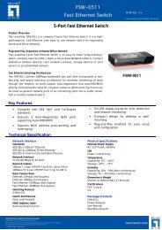
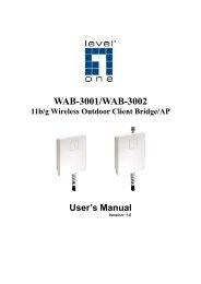
Figure 2 Remote deployment with RAPs <strong>and</strong> VIA clients<br />
DMZ<br />
Local<br />
active<br />
From Data Center<br />
Public Access Sites<br />
Local<br />
active<br />
Internet or<br />
WAN<br />
Public<br />
Hotspot<br />
Branch Office Sites<br />
Fixed<br />
Telecommuter<br />
Sites<br />
Broadb<strong>and</strong><br />
Carrier<br />
3G<br />
EVDO/GSM<br />
Carrier<br />
Cable<br />
Provider<br />
3G<br />
EVDO/GSM<br />
Carrier<br />
RAP-5WN<br />
RAP-5<br />
RAP-2WG<br />
RAP-5WN<br />
Medium Branch<br />
Small Branch<br />
Remote Call<br />
Center Agent<br />
RNSG_120<br />
Fixed Telecommuter<br />
arun_0208<br />
<strong>Aruba</strong> <strong>Mobility</strong> <strong>Controllers</strong> <strong>and</strong> <strong>Deployment</strong> <strong>Models</strong> VRD | Solution Guide Summary of Recommendations | 11
The following table summarizes the recommendations for RAP <strong>and</strong> VIA-based deployments.<br />
Table 2 Remote <strong>Deployment</strong> Recommendations<br />
Feature or Function<br />
Master/local or all masters<br />
Physical location of the master mobility<br />
controller<br />
Master mobility controller redundancy<br />
Physical location of the local mobility<br />
controller<br />
Local mobility controller redundancy<br />
Local mobility controller load<br />
VIA agents<br />
AirWave Wireless Management Suite<br />
Recommendation<br />
Use a master/local configuration.<br />
Network data center: Put the master mobility controller in the<br />
network data center if the <strong>Aruba</strong> deployment is pervasive.<br />
DMZ: Put the master mobility controller in the DMZ if <strong>Aruba</strong> is<br />
used only for remote networking.<br />
Use master redundancy with a st<strong>and</strong>by master.<br />
Put the local mobility controller in the network DMZ.<br />
Use active-active, with two mobility controllers <strong>and</strong> two instances<br />
of the VRRP. Each mobility controller should be the primary on<br />
one of the VRRP instances, <strong>and</strong> back-up for the other. Half of the<br />
APs should terminate on each of the two VRRP instances.<br />
AP <strong>and</strong> user load to 40% capacity, which results in 80% load in a<br />
failure condition.<br />
Use the VIA agent on laptops that need to communicate over<br />
untrusted connections where a RAP deployment is not feasible.<br />
Deploy AWMS for management, configuration, reporting, <strong>and</strong><br />
troubleshooting. Deploy AWMS in the network data center.<br />
Licenses • AP capacity equal to the number of RAPs supported during a<br />
failover scenario.<br />
• PEF-NG for user roles, firewall policy, equal to the number of<br />
RAPs supported during a failover scenario.<br />
• PEF-V for VIA client firewall policy.<br />
• WIP for advanced wireless intrusion protection <strong>and</strong> rogue<br />
detection, equal to the number of RAPs supported during a<br />
failover scenario.<br />
12 | Summary of Recommendations <strong>Aruba</strong> <strong>Mobility</strong> <strong>Controllers</strong> <strong>and</strong> <strong>Deployment</strong> <strong>Models</strong> VRD | Solution Guide
Branch Offices<br />
The branch office is an extension of a larger organization. Typically, the branch office has a data center<br />
located at a remote site where additional services are provided. The branch office is characterized by<br />
being large enough to require multiple APs to service local clients. Often the branch office has a<br />
requirement for survivability in the event of a WAN outage.<br />
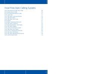
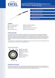
Figure 3 Branch office controller deployment with guest access<br />
To DMZ<br />
Internet or<br />
WAN<br />
To Internet<br />
Destinations<br />
3G<br />
WWAN<br />
DSL<br />
MPLS<br />
Frame<br />
Relay<br />
Enterprise<br />
IP Address Pool<br />
Voice<br />
SSID<br />
BOC<br />
RAP<br />
IP Address Pool<br />
(Local DHCP)<br />
Pre-Shared<br />
Key SSID<br />
Enterprise<br />
SSID<br />
Guest<br />
SSID<br />
VLAN 177<br />
192.168.177.0/24<br />
Enterprise<br />
Wired Access<br />
HTTPS<br />
Application<br />
Server<br />
Guest<br />
Wired Access<br />
arun_0207<br />
<strong>Aruba</strong> <strong>Mobility</strong> <strong>Controllers</strong> <strong>and</strong> <strong>Deployment</strong> <strong>Models</strong> VRD | Solution Guide Summary of Recommendations | 13
The following table summarizes the recommendations for branch office deployments, with the<br />
assumption that a central corporate site exists elsewhere.<br />
Table 3 Branch Office Recommendations<br />
Feature or Function<br />
Master/local or all masters<br />
Location of the master mobility controller<br />
Master mobility controller redundancy<br />
Location of the local mobility controller<br />
Local mobility controller redundancy<br />
Local mobility controller load<br />
VIA agents<br />
AirWave Wireless Management Suite<br />
Recommendation<br />
Use an all masters configuration.<br />
Put the master mobility controller in the networking closet.<br />
Use master redundancy using a st<strong>and</strong>by-master, or N+1 for larger<br />
branches with private WAN connections.<br />
N/A<br />
N/A<br />
N/A<br />
Use the VIA agent on laptops that need to communicate over<br />
untrusted connections where a RAP deployment is not feasible.<br />
Deploy AWMS for management, configuration, reporting, <strong>and</strong><br />
troubleshooting. Deploy AWMS in the network data center.<br />
Licenses • AP capacity equal to the number of RAPs supported during a<br />
failover scenario.<br />
• PEF-NG for user roles, firewall policy, equal to the number of<br />
RAPs supported during a failover scenario.<br />
• PEF-V for VIA client firewall policy.<br />
• WIP for advanced wireless intrusion protection <strong>and</strong> rogue<br />
detection, equal to the number of RAPs supported during a<br />
failover scenario.<br />
14 | Summary of Recommendations <strong>Aruba</strong> <strong>Mobility</strong> <strong>Controllers</strong> <strong>and</strong> <strong>Deployment</strong> <strong>Models</strong> VRD | Solution Guide
Small Offices with Single Sites<br />
In some cases, an organization is small enough that a single mobility controller is sufficient to h<strong>and</strong>le<br />
the networking needs of the organization. Typical cases include doctors offices, law firms, design firms,<br />
<strong>and</strong> architects offices. Typically the organization either has no other site, or they are few in number <strong>and</strong><br />
can be h<strong>and</strong>led by RAPs <strong>and</strong> VIA clients that terminate on the same mobility controller.<br />
Figure 4 Small branch deployment with a mobility controller onsite<br />
Small<br />
Site<br />
Master<br />
active<br />
Data<br />
Air Monitor<br />
arun_0280<br />
The following table summarizes the recommendations for small organizations.<br />
Table 4 Small Office <strong>Deployment</strong> Recommendations<br />
Feature or Function<br />
Master/local or all masters<br />
Location of the master mobility controller<br />
Master mobility controller redundancy<br />
Location of the local mobility controller<br />
Local mobility controller redundancy<br />
Local mobility controller load<br />
VIA agents<br />
AirWave Wireless Management Suite<br />
(AWMS)<br />
Recommendation<br />
Use an all masters configuration.<br />
Put the master mobility controller in the networking closet.<br />
Use master redundancy, using a st<strong>and</strong>by-master if possible.<br />
N/A<br />
N/A<br />
N/A<br />
Use VIA agents on laptops that need to communicate over untrusted<br />
connections where a RAP deployment is not feasible.<br />
If possible, deploy AWMS for management, configuration,<br />
reporting, <strong>and</strong> troubleshooting. Deploy AWMS in the network<br />
data center.<br />
<strong>Aruba</strong> <strong>Mobility</strong> <strong>Controllers</strong> <strong>and</strong> <strong>Deployment</strong> <strong>Models</strong> VRD | Solution Guide Summary of Recommendations | 15
Table 4 Small Office <strong>Deployment</strong> Recommendations (Continued)<br />
Feature or Function<br />
Recommendation<br />
Licenses • AP capacity equal to the number of RAPs supported during a<br />
failover scenario.<br />
• PEF-NG for user roles, firewall policy, equal to the number of<br />
RAPs supported during a failover scenario.<br />
• PEF-V for VIA client firewall policy.<br />
• WIP for advanced wireless intrusion protection <strong>and</strong> rogue<br />
detection, equal to the number of RAPs supported during a<br />
failover scenario.<br />
16 | Summary of Recommendations <strong>Aruba</strong> <strong>Mobility</strong> <strong>Controllers</strong> <strong>and</strong> <strong>Deployment</strong> <strong>Models</strong> VRD | Solution Guide
Chapter 3<br />
Underst<strong>and</strong>ing the<br />
<strong>Aruba</strong> <strong>Mobility</strong> Controller<br />
<strong>and</strong> AWMS<br />
The <strong>Aruba</strong> <strong>Mobility</strong> Controller is the heart of the <strong>Aruba</strong> dependent access point (AP) WLAN<br />
architecture. The mobility controller is responsible for many of the operations that traditionally would<br />
be h<strong>and</strong>led by the AP in an autonomous AP deployment. The mobility controller acts as a comm<strong>and</strong><strong>and</strong>-control<br />
point for the network as a whole. The mobility controller operates as an access network<br />
with APs <strong>and</strong> as a wireless intrusion prevention (WIP) system with dedicated AMs that perform<br />
scanning <strong>and</strong> containment operations on the WLAN.<br />
The <strong>Aruba</strong> <strong>Mobility</strong> Controller goes far beyond managing dependent APs. The mobility controller is<br />
capable of fulfilling many of the roles that traditionally were h<strong>and</strong>led by dedicated appliances. The<br />
functionality that the mobility controller provides includes:<br />
• Acting as a user-based stateful firewall<br />
• Terminating user-encrypted sessions from wireless devices<br />
• Performing Layer 2 switching <strong>and</strong> Layer 3 routing<br />
• Providing clientless Layer 3 mobility<br />
• Acting as an IPsec virtual private network (VPN) concentrator for site-to-site <strong>and</strong> client-based VPNs<br />
• Providing certificate-based IPsec security to protect control channel information<br />
• Terminating Internet-based RAPs<br />
• Providing wired firewall services<br />
• Performing user authentication with 802.1X <strong>and</strong> captive portal authentication, among others<br />
• Providing guest access <strong>and</strong> provisioning services<br />
• Providing advanced RF services with Adaptive Radio Management (ARM) <strong>and</strong> spectrum analysis<br />
• Providing location services <strong>and</strong> RF coverage “heat maps” of the deployment<br />
• Performing rogue detection <strong>and</strong> containment<br />
• Providing self-contained management by way of a master/local hierarchy with one controller<br />
pushing configuration to other mobility controllers to reduce administrative overhead<br />
• Delivering AP software updates automatically when the mobility controller is upgraded<br />
This level of seamless, integrated functionality eliminates many of the challenges experienced with<br />
traditional systems integration for these services. Network administrators need to learn only one<br />
interface, which reduces complexity <strong>and</strong> speeds problem resolution across a broad range of solutions.<br />
For larger or more distributed organizations, the <strong>Aruba</strong> AirWave Wireless Management Suite (AWMS)<br />
provides overall configuration <strong>and</strong> reporting capabilities to complement the management tools that are<br />
built into the controller. Features include configuration across multiple master/local clusters, long-term<br />
reporting, location services, <strong>and</strong> advanced rogue AP detection tools in a highly scalable solution.<br />
<strong>Aruba</strong> <strong>Mobility</strong> <strong>Controllers</strong> <strong>and</strong> <strong>Deployment</strong> <strong>Models</strong> VRD | Solution Guide Underst<strong>and</strong>ing the <strong>Aruba</strong> <strong>Mobility</strong> Controller <strong>and</strong> AWMS | 17
The <strong>Aruba</strong> system has a logical four-tier operating model that consists of four layers: management,<br />
network services, aggregation, <strong>and</strong> network access. <strong>Controllers</strong> operate at the network services <strong>and</strong><br />
aggregation layers, APs operate at the network access layer, <strong>and</strong> AWMS operates at the management<br />
level. This model is used throughout the VRD program to describe the logical deployment of the <strong>Aruba</strong><br />
solution.<br />
Figure 5 Logical four-tier operating model<br />
Management<br />
AWMS<br />
Server<br />
Data Center<br />
Network<br />
Services<br />
Master<br />
active<br />
Master<br />
st<strong>and</strong>by<br />
POS<br />
File<br />
PBX<br />
RADIUS<br />
Control<br />
Aggregation<br />
Local<br />
active<br />
Local<br />
active<br />
Data<br />
Network<br />
Access<br />
Retail_107<br />
Air<br />
Monitor<br />
Air<br />
Monitor<br />
arun_0202<br />
18 | Underst<strong>and</strong>ing the <strong>Aruba</strong> <strong>Mobility</strong> Controller <strong>and</strong> AWMS <strong>Aruba</strong> <strong>Mobility</strong> <strong>Controllers</strong> <strong>and</strong> <strong>Deployment</strong> <strong>Models</strong> VRD | Solution Guide
Controller Overview<br />
The mobility controllers are available in modular chassis models <strong>and</strong> as network appliances that scale<br />
to meet the needs of the largest organizations. This section introduces the current generation of<br />
mobility controllers.<br />
<strong>Aruba</strong> 6000 Chassis <strong>and</strong> M3 Blade<br />
Figure 6 <strong>Aruba</strong> 6000 Chassis with four M3 <strong>Mobility</strong> Controller Blades<br />
The <strong>Aruba</strong> 6000 Chassis is designed to address a wide range of wireless <strong>and</strong> wired network mobility,<br />
security, <strong>and</strong> remote networking requirements for corporate headquarters <strong>and</strong> large campus<br />
deployments. The <strong>Aruba</strong> 6000 is easy to install without disrupting the existing wired network. Edge<br />
services are virtualized <strong>and</strong> implemented in cost-effective APs at the network edge. The APs move user<br />
traffic to data center controllers through secure IP tunnels over a public or private transport network.<br />
The <strong>Aruba</strong> 6000 runs the <strong>Aruba</strong>OS operating system <strong>and</strong> comes st<strong>and</strong>ard with advanced authentication,<br />
encryption, wireless radio management, secure enterprise wireless mesh, <strong>and</strong> Layer 2 <strong>and</strong> Layer 3<br />
networking features. Optional <strong>Aruba</strong>OS software modules deliver additional functionality, including<br />
policy enforcement firewall, VPN server, remote access gateway, <strong>and</strong> WIP.<br />
<strong>Aruba</strong> 3000 Series<br />
Figure 7 <strong>Aruba</strong> 3000 Series <strong>Mobility</strong> <strong>Controllers</strong><br />
The <strong>Aruba</strong> 3200 <strong>Mobility</strong> Controller is designed for the small <strong>and</strong> branch offices, <strong>and</strong> the <strong>Aruba</strong> 3400<br />
<strong>and</strong> <strong>Aruba</strong> 3600 <strong>Mobility</strong> <strong>Controllers</strong> are designed for medium <strong>and</strong> large enterprise or dense office<br />
<strong>Aruba</strong> <strong>Mobility</strong> <strong>Controllers</strong> <strong>and</strong> <strong>Deployment</strong> <strong>Models</strong> VRD | Solution Guide Underst<strong>and</strong>ing the <strong>Aruba</strong> <strong>Mobility</strong> Controller <strong>and</strong> AWMS | 19
deployments. Edge services are virtualized <strong>and</strong> implemented in cost-effective APs at the network edge.<br />
The APs move user traffic to data center controllers through secure IP tunnels over a public or private<br />
transport network. The <strong>Aruba</strong> 3000 Series runs the <strong>Aruba</strong>OS operating system <strong>and</strong> comes st<strong>and</strong>ard with<br />
advanced authentication, encryption, wireless radio management, secure enterprise wireless mesh, <strong>and</strong><br />
Layer 2 <strong>and</strong> Layer 3 networking features. Optional <strong>Aruba</strong>OS software modules deliver additional<br />
functionality, including policy enforcement firewall, VPN server, remote access gateway, <strong>and</strong> WIP.<br />
600 Series<br />
Figure 8 651 Controller Branch Office Controller with Integrated AP<br />
The <strong>Aruba</strong> 600 Series of controllers are integral components of the <strong>Aruba</strong> distributed enterprise<br />
network, which uses central controllers in the data center to manage complex <strong>and</strong> processing-intensive<br />
management <strong>and</strong> security functions. Edge services are virtualized <strong>and</strong> implemented in cost-effective<br />
edge devices, which move user traffic to data center controllers through secure IP tunnels over a public<br />
or private transport network. The <strong>Aruba</strong> 600 Series provides local wireless services when used in<br />
conjunction with any <strong>Aruba</strong> AP, or they can operate as wired-only devices. The controllers also include<br />
print server <strong>and</strong> network-attached storage capabilities to enable local network printing <strong>and</strong> mass<br />
storage.<br />
Next Steps<br />
The next three sections discuss the deployment operating modes <strong>and</strong> deployment options for the<br />
system components. The first section describes the different operating modes of the <strong>Aruba</strong> <strong>Mobility</strong><br />
<strong>Controllers</strong> <strong>and</strong> explains the functions of the master <strong>and</strong> local controller. The second section explains<br />
the advantages of adding AWMS to the WLAN to increase management capabilities. Finally, the third<br />
section describes the various deployment models that allow <strong>Aruba</strong> WLANs to scale from the largest<br />
campus to the smallest home office.<br />
Underst<strong>and</strong>ing <strong>Mobility</strong> Controller Master/Local Model<br />
All <strong>Aruba</strong> <strong>Mobility</strong> <strong>Controllers</strong> are capable of assuming two operating roles in the system: master or<br />
local mobility controller. This hierarchy allows organizations to build scalable WLAN networks without<br />
requiring additional management platforms when the network is contained to a single master/local<br />
cluster.<br />
The master mobility controller is the central point of coordination <strong>and</strong> configuration of the network.<br />
The master mobility controller processes all wireless security events <strong>and</strong> sends policy-based<br />
20 | Underst<strong>and</strong>ing the <strong>Aruba</strong> <strong>Mobility</strong> Controller <strong>and</strong> AWMS <strong>Aruba</strong> <strong>Mobility</strong> <strong>Controllers</strong> <strong>and</strong> <strong>Deployment</strong> <strong>Models</strong> VRD | Solution Guide
configuration to the local mobility controllers. The local mobility controllers manage the CAPs, air<br />
monitors (AMs), RAPs, VPN clients, <strong>and</strong> devices attached to the WLAN. APs connect directly to the<br />
local mobility controller over an IP-based network, <strong>and</strong> in most deployments, all traffic from devices is<br />
sent to the local mobility controller for processing.<br />
Underst<strong>and</strong>ing the Master <strong>Mobility</strong> Controller<br />
The role of the master mobility controller in an <strong>Aruba</strong> WLAN is to provide a single point of policy<br />
configuration <strong>and</strong> coordination for the WLAN in smaller deployments. The master mobility controller<br />
can receive configuration <strong>and</strong> coordination information from the AWMS for larger or more distributed<br />
deployments. A typical master/local cluster consists of one master mobility controller <strong>and</strong> one or more<br />
local mobility controllers. However, in smaller deployments the master also can h<strong>and</strong>le all functions of<br />
the local. The communication channel between the master <strong>and</strong> locals is protected using IPsec. The<br />
master mobility controller typically does not terminate any clients or APs directly.<br />
Figure 9 Network services layer<br />
Management<br />
AWMS<br />
Server<br />
Data Center<br />
Network<br />
Services<br />
Master<br />
active<br />
Master<br />
st<strong>and</strong>by<br />
POS<br />
File<br />
PBX<br />
RADIUS<br />
Internet<br />
Aggregation<br />
Local<br />
<strong>Mobility</strong> Controller<br />
Local<br />
<strong>Mobility</strong><br />
Controller<br />
Network<br />
Access<br />
at the<br />
APs<br />
Air Monitor<br />
arun_042<br />
arun_0283<br />
<strong>Aruba</strong> <strong>Mobility</strong> <strong>Controllers</strong> <strong>and</strong> <strong>Deployment</strong> <strong>Models</strong> VRD | Solution Guide Underst<strong>and</strong>ing the <strong>Aruba</strong> <strong>Mobility</strong> Controller <strong>and</strong> AWMS | 21
Master mobility controllers are responsible for the following functions in the WLAN:<br />
• Policy configuration: Configuration in the <strong>Aruba</strong> solution is split between policy <strong>and</strong> local<br />
configurations. Local configuration deals with things such as physical interfaces, IP networking, <strong>and</strong><br />
VLANs. Policy configuration is centered on the operation of APs <strong>and</strong> users, including AP settings<br />
such as the SSID name, encryption, regulatory domain, channel, power, <strong>and</strong> ARM settings. Policy<br />
configuration extends beyond APs <strong>and</strong> also covers user authentication, firewall policy, mobility<br />
domains (IP mobility), IPsec settings, <strong>and</strong> system management. The policy is pushed to all local<br />
mobility controllers in the form of profiles, <strong>and</strong> profiles combine to create the configuration for the<br />
dependant APs.<br />
• AP white lists: Two types of white lists exist in the system, one for RAPs <strong>and</strong> one for CAPs that use<br />
CPsec. These lists determine which APs can connect to the mobility controllers <strong>and</strong> in which<br />
method of operation. These lists give organizations additional levels of control. Unauthorized<br />
devices are prevented from connecting to the network, <strong>and</strong> provisioning of the system is simplified.<br />
• WIP coordination: Wireless intrusion prevention (WIP) activities involve looking for rogue<br />
(unauthorized) APs <strong>and</strong> monitoring for attacks on the WLAN infrastructure or clients. The master<br />
controller processes all data collected by <strong>Aruba</strong> Wi-Fi sensors known as AMs. Instructions to disable<br />
a rogue AP or blacklist a client from the network are issued through the master mobility controller.<br />
• Valid AP list: Separate from the concept of the white list, all of the legitimate APs operating on the<br />
WLAN must also be known to all mobility controllers in the network, <strong>and</strong> they must be marked as<br />
being valid APs. This list prevents valid APs from being falsely flagged as rogue APs when APs that<br />
are attached to two different local mobility controllers are close enough to hear each other’s<br />
transmissions on a single site. This list also helps ARM to differentiate between APs that generate<br />
noise (third-party or not under control of the mobility controller) <strong>and</strong> those that are part of the valid<br />
coverage area, but are generating co-channel interference. Unlike traditional wireless intrusion<br />
detection system (WIDS) solutions, the master controller automatically generates the valid AP list<br />
without network administrator intervention. All <strong>Aruba</strong> APs are automatically learned <strong>and</strong> added to<br />
the list, but valid third-party APs must be added manually. If more than one master/local cluster<br />
exists, AirWave should be deployed to coordinate APs between clusters.<br />
• RF visualization: Unlike traditional wired networks, RF requires additional tools to visualize<br />
network coverage. The <strong>Aruba</strong> RF visualization tools provide a real-time view of the network<br />
coverage. The entire network or coverage in a particular b<strong>and</strong>, channel, or speed can be selected.<br />
This information is based on the AP channel <strong>and</strong> power settings <strong>and</strong> the data collected from AMs<br />
<strong>and</strong> APs listening to transmissions during their scanning periods. This information provides a<br />
realistic picture of the actual RF coverage as opposed to predictive planning tools. Predictive tools<br />
cannot provide anything more than a model of what should occur in the network based on estimates<br />
using AP placement <strong>and</strong> wall materials.<br />
• Location: Much like visualization, locating users in the WLAN is more difficult with mobile clients<br />
<strong>and</strong> IP mobility. The WLAN is not only serving clients but is also scanning off channel, so it is<br />
possible to triangulate users <strong>and</strong> rogue devices to within a small area. This information is displayed<br />
on the master <strong>and</strong> allows for devices to be located quickly, which is critically important for physical<br />
security <strong>and</strong> advanced services such as E911 calling.<br />
• Initial AP configuration: When an AP first boots up, it contacts its master mobility controller to<br />
receive the configuration generated by the master. The AP can use DNS lookup, DHCP option 43,<br />
broadcast, multicast, or static configurations to locate the master, which creates a “plug-<strong>and</strong>-play”<br />
experience when APs are added to the network. The master compares the AP name <strong>and</strong> determines<br />
its group assignment, <strong>and</strong> then redirects that AP to the proper local mobility controller. The most<br />
common methods are DNS <strong>and</strong> DHCP options, which allow changes to propagate quickly through<br />
the system <strong>and</strong> eliminate the need for Layer 2 connectivity to the master.<br />
• Control plane security: When CPsec is enabled, the master mobility controller generates the selfsigned<br />
certificate <strong>and</strong> acts as the certificate authority (CA) for the network. The master mobility<br />
controller issues certificates to all local mobility controllers in the network as well. If more than one<br />
22 | Underst<strong>and</strong>ing the <strong>Aruba</strong> <strong>Mobility</strong> Controller <strong>and</strong> AWMS <strong>Aruba</strong> <strong>Mobility</strong> <strong>Controllers</strong> <strong>and</strong> <strong>Deployment</strong> <strong>Models</strong> VRD | Solution Guide
master exists in the network, the network administrator assigns a single master as the trust anchor<br />
for that network. The trust anchor issues certificates to the other master controllers in the network.<br />
• Authentication <strong>and</strong> roles: User authentication methods <strong>and</strong> role assignments are created on the<br />
master mobility controller <strong>and</strong> then propagated to local mobility controllers throughout the<br />
network. A database exists to authenticate users in small deployments or for guest access<br />
credentials that can be leveraged by all the mobility controllers in the network. Additionally, the<br />
master can also proxy requests for the network to a RADIUS or LDAP server.<br />
Underst<strong>and</strong>ing the Local <strong>Mobility</strong> Controller<br />
The local mobility controller controls its logically attached APs <strong>and</strong> h<strong>and</strong>les user sessions on the<br />
network. The locals process the majority of the traffic on the network. When the locals terminate CAPs,<br />
the locals are typically deployed either in the distribution layer or network data center, depending on<br />
the distribution of traffic in the enterprise. In the case of RAPs, Branch Office <strong>Controllers</strong> (BOCs), <strong>and</strong><br />
VIA agents, the locals are typically located in the network DMZ.<br />
Figure 10 Aggregation layer<br />
Management<br />
AWMS<br />
Server<br />
Data Center<br />
Network<br />
Services<br />
Master<br />
active<br />
Master<br />
st<strong>and</strong>by<br />
POS<br />
File<br />
PBX<br />
RADIUS<br />
Internet<br />
Aggregation<br />
Local<br />
<strong>Mobility</strong> Controller<br />
Local<br />
<strong>Mobility</strong><br />
Controller<br />
Network<br />
Access<br />
at the<br />
APs<br />
Air Monitor<br />
arun_0205<br />
<strong>Aruba</strong> <strong>Mobility</strong> <strong>Controllers</strong> <strong>and</strong> <strong>Deployment</strong> <strong>Models</strong> VRD | Solution Guide Underst<strong>and</strong>ing the <strong>Aruba</strong> <strong>Mobility</strong> Controller <strong>and</strong> AWMS | 23
Local mobility controllers are responsible for the following functions in the WLAN:<br />
• AP <strong>and</strong> AM configuration <strong>and</strong> software updates: All <strong>Aruba</strong> APs are dependent APs, which<br />
means they do not in most instances store configuration settings in the way that a traditional<br />
autonomous AP would. Instead, at boot time each AP downloads its current configuration from the<br />
local mobility controller. When changes are made in the system configuration, they are<br />
automatically pushed to all APs. Whenever an AP boots, it will always have the current<br />
configuration, <strong>and</strong> changes are reflected immediately throughout the network. When the software<br />
on the mobility controller is updated, the APs automatically download a new image from the<br />
mobility controller <strong>and</strong> upgrade themselves. This software check, like the configuration download,<br />
is part of the AP boot process, <strong>and</strong> it insures that each AP has the current operating image <strong>and</strong><br />
configuration without user intervention.<br />
• AP <strong>and</strong> AM termination: The local mobility controller is the location where the AP terminates<br />
after it contacts the master mobility controller. The local upgrades the APs operating system as<br />
necessary, <strong>and</strong> it pushes the APs configuration to it. In the majority of campus deployments, all user<br />
traffic is sent from the AP to the local mobility controller <strong>and</strong> the local h<strong>and</strong>les the decryption of the<br />
wireless frame. AMs also terminate on the local, but their traffic is sent directly to the master<br />
mobility controller to h<strong>and</strong>le WIP coordination between AMs <strong>and</strong> APs. In an <strong>Aruba</strong> system, user<br />
traffic is sent over GRE tunnels to the local mobility controller. Control traffic also uses the GRE<br />
tunnel, but if CPsec is enabled, control traffic uses a separate IPsec tunnel.<br />
• User session termination: An <strong>Aruba</strong> network is focused on the client devices, which are<br />
commonly referred to as users. User sessions are any information transmitted from a client device<br />
across the WLAN, from actual human users on a wireless device to wireless IP cameras to medical<br />
equipment <strong>and</strong> scanner guns. Every user in an <strong>Aruba</strong> system is identified when they authenticate to<br />
the system (by WLAN, IPsec, or wired with captive portal), <strong>and</strong> their login information is used to<br />
place the user in the appropriate role based on that login. The user’s role defines what that user is<br />
allowed to do on the network. This definition is enforced by an ICSA 1 certified stateful firewall, with<br />
a role-based policy applied to every user. By applying the policy to the individual users, <strong>Aruba</strong><br />
eliminates the need to focus on ports as a security mechanism. Instead security moves to the user<br />
level, which allows multiple users to share a single AP or wired port <strong>and</strong> receive the appropriate<br />
level of security based on whom they are, not where they connect.<br />
• ARM assignments <strong>and</strong> load balancing: <strong>Aruba</strong> ARM controls aspects of AP <strong>and</strong> client<br />
performance. All WLANs operate in unlicensed space, so the chance that something will interfere is<br />
very high. <strong>Aruba</strong> has developed a system to automatically work around interference <strong>and</strong> help clients<br />
have a better operating experience. These features include automatically tuning the WLAN by<br />
automatically configuring AP power <strong>and</strong> channel settings, as well as scanning for better settings <strong>and</strong><br />
avoiding interference. ARM also h<strong>and</strong>les AP load balancing <strong>and</strong> co-channel interference from other<br />
APs <strong>and</strong> clients, as well as airtime fairness to ensure that slower speed clients do not bring down the<br />
throughput of higher-speed clients. Using b<strong>and</strong> steering, when the system detects a client is capable<br />
of operating on the 5 GHz b<strong>and</strong> (the majority of modern clients), the system automatically attempts<br />
to steer that client to the cleaner b<strong>and</strong>.<br />
• WIP enforcement <strong>and</strong> blacklisting: While the master h<strong>and</strong>les the processing of WIP information,<br />
the local directs the actions of the AMs for enforcement of WIP policy. Enforcement can take<br />
different shapes, including containing rogue APs by performing denial-of-service (DoS) attacks<br />
wirelessly, ARP cache poisoning on the wire, shielding valid clients from connecting to rogue APs,<br />
<strong>and</strong> blacklisting clients so that they are unable to attach to the WLAN.<br />
1. ICSA labs provides vendor neutral testing of products <strong>and</strong> certifies them in compliance with a set of common tests <strong>and</strong><br />
criteria. ICSA is on the web at http://www.icsalabs.com/<br />
24 | Underst<strong>and</strong>ing the <strong>Aruba</strong> <strong>Mobility</strong> Controller <strong>and</strong> AWMS <strong>Aruba</strong> <strong>Mobility</strong> <strong>Controllers</strong> <strong>and</strong> <strong>Deployment</strong> <strong>Models</strong> VRD | Solution Guide
• CPsec AP certification: When CPsec is enabled in the WLAN, the AP <strong>and</strong> local mobility controller<br />
establish an IPsec tunnel between the two devices using certificates. The local mobility controller is<br />
responsible for issuing these certificates, <strong>and</strong> in some instances adding APs to the white list. When<br />
the AP boots up <strong>and</strong> tries to contact the local mobility controller, the certificates are used to build<br />
an IPsec tunnel between the devices.<br />
• <strong>Mobility</strong>: Supports both Layer 2 (VLAN) mobility as well as Layer 3 (IP) mobility, allowing users to<br />
seamlessly roam between APs on different mobility controllers without session interruption. This is<br />
a key component to support VoIP sessions, where sessions must be preserved.<br />
• Quality of service (QoS): The mobility controllers support QoS on the wired <strong>and</strong> wireless side.<br />
This support includes translating DiffServ <strong>and</strong> ToS bits set on packets into Wi-Fi Multimedia<br />
(WMM®) markings <strong>and</strong> back. The <strong>Aruba</strong> policy enforcement firewall (PEF) also allows the<br />
administrator to mark packets with the appropriate level of QoS, <strong>and</strong> to change markings on packets<br />
entering the system.<br />
<strong>Aruba</strong> <strong>Mobility</strong> <strong>Controllers</strong> <strong>and</strong> <strong>Deployment</strong> <strong>Models</strong> VRD | Solution Guide Underst<strong>and</strong>ing the <strong>Aruba</strong> <strong>Mobility</strong> Controller <strong>and</strong> AWMS | 25
Underst<strong>and</strong>ing the Role of the AirWave Wireless Management<br />
Suite<br />
The management framework built in to the master mobility controller was developed to allow smallscale<br />
networks to operate without the need of a dedicated management platform. When the system was<br />
first developed, Wi-Fi networks were convenience networks that were used only in meeting rooms <strong>and</strong><br />
usually by guests. As Wi-Fi moved from providing only guest access to being the primary connection<br />
medium, the mission-critical nature dem<strong>and</strong>ed new tools to manage the network.<br />
Figure 11 Management layer<br />
Management<br />
AWMS<br />
Server<br />
Data Center<br />
Network<br />
Services<br />
Master<br />
active<br />
Master<br />
st<strong>and</strong>by<br />
POS<br />
File<br />
PBX<br />
RADIUS<br />
Internet<br />
Aggregation<br />
Local<br />
<strong>Mobility</strong> Controller<br />
Local<br />
<strong>Mobility</strong><br />
Controller<br />
Network<br />
Access<br />
at the<br />
APs<br />
Air Monitor<br />
arun_042<br />
arun_0204<br />
26 | Underst<strong>and</strong>ing the <strong>Aruba</strong> <strong>Mobility</strong> Controller <strong>and</strong> AWMS <strong>Aruba</strong> <strong>Mobility</strong> <strong>Controllers</strong> <strong>and</strong> <strong>Deployment</strong> <strong>Models</strong> VRD | Solution Guide
The AirWave Wireless Management Suite (AWMS) fills this role by providing best-in-breed network<br />
management. AWMS enhances the features that are already delivered by the master controller <strong>and</strong><br />
allows the WLAN to scale to much larger deployments. AirWave increases the functionality <strong>and</strong><br />
usability of the <strong>Aruba</strong> <strong>Mobility</strong> Controller control plane in the following ways:<br />
• Historical data: The largest <strong>Aruba</strong> <strong>Mobility</strong> Controller contains 512 MB of flash memory, <strong>and</strong> an<br />
AirWave appliance contains multiple hard drives with 100+ GB of capacity. The <strong>Aruba</strong> <strong>Mobility</strong><br />
Controller can typically store 1-4 days of data, <strong>and</strong> an AirWave appliance can store 1+ year.<br />
• Scalability: A master <strong>Aruba</strong> <strong>Mobility</strong> Controller can effectively manage up to 50,000 objects<br />
including APs, clients, <strong>and</strong> local mobility controllers. To avoid overloading a master mobility<br />
controller, real-time user information is also limited in larger networks. The controller polls for realtime<br />
data on-dem<strong>and</strong> rather than continuously collecting it. The AirWave Master Console can be<br />
used to manage over 75,000 APs, hundreds of controllers, <strong>and</strong> hundreds of thous<strong>and</strong>s of users. Data<br />
is collected continuously <strong>and</strong> in real time so that problems can be diagnosed after the fact by using<br />
historical data.<br />
• Reporting: To assess performance <strong>and</strong> network capacity, it is not enough to look at real-time<br />
network data in isolation. Trend data from months or years can help to determine how current<br />
conditions compare to previous levels <strong>and</strong> how changing usage patterns may impact network<br />
performance. AWMS provides up to 2 years of actionable information, including network<br />
performance data <strong>and</strong> user roaming patterns. AWMS also provides the detailed capacity reports that<br />
are needed to plan for adequate coverage across the current network, network expansion, or<br />
802.11n upgrades. Reports can be scheduled to run automatically <strong>and</strong> are emailed out, which<br />
eliminates the need to manually generate reports or log into the server to check status.<br />
• Alerting: Automated alerts can be sent using SNMP, syslog, or email, <strong>and</strong> the alerts can be<br />
configured to cover the entire system or only portions of the network. Alerting is available for a<br />
range of issues including radio state, user b<strong>and</strong>width, <strong>and</strong> rogue AP detection.<br />
• Advanced RF tools: AWMS can provide real-time views of the RF coverage in an organization <strong>and</strong><br />
provide “heat maps” of that coverage on floor plans where APs <strong>and</strong> AMs are deployed. Additionally,<br />
these same maps can be used to locate client stations, rogue APs, <strong>and</strong> 802.11 RFID tags. Additional<br />
tools make it possible to plan network deployments using VisualRF Plan to do AP deployment<br />
planning software, without the need for more expensive manual surveys in many cases. This<br />
planning is backed up by VisualRF, which delivers a real-time view of the network as it operates.<br />
• Managing multiple master/local clusters: An AWMS can monitor <strong>and</strong> control multiple master<br />
<strong>Aruba</strong> <strong>Mobility</strong> <strong>Controllers</strong> <strong>and</strong> their associated local mobility controllers. Configuration auditing<br />
<strong>and</strong> reporting is also available to ensure that all devices are configured as expected, <strong>and</strong> that<br />
changes to the system are recorded. In addition, software can be pushed to the mobility controllers<br />
along with scheduled reboots to upgrade the system.<br />
• Executive <strong>and</strong> help desk monitoring views: The <strong>Aruba</strong>OS WebUI is primarily intended for<br />
network engineers to conduct configuration <strong>and</strong> monitoring. An AirWave Management Suite<br />
provides multiple customized interfaces appropriate to different roles in the organization. AWMS<br />
also allows for multiple user roles with different permissions on the system, as well as the ability to<br />
group devices to provide permissions to a subset of the network. Open APIs allow for integration<br />
into existing network management <strong>and</strong> trouble ticket systems.<br />
• Management of third-party devices – The AWMS is the premiere multivendor wireless<br />
management suite on the market. Many large organizations have a mixture of wireless equipment,<br />
new <strong>and</strong> old, <strong>and</strong> are slowly migrating from one system to the other. The AWMS allows network<br />
managers to transition from legacy platforms to the <strong>Aruba</strong> solution using a single interface for<br />
management.<br />
• Wired network rogue AP scans: The AirWave RAPIDS module can scan networks for rogue APs<br />
even when no wireless sensors are present. When the RAPIDS module is combined with the<br />
<strong>Aruba</strong>OS WIP module, comprehensive rogue detection <strong>and</strong> containment is provided.<br />
<strong>Aruba</strong> <strong>Mobility</strong> <strong>Controllers</strong> <strong>and</strong> <strong>Deployment</strong> <strong>Models</strong> VRD | Solution Guide Underst<strong>and</strong>ing the <strong>Aruba</strong> <strong>Mobility</strong> Controller <strong>and</strong> AWMS | 27
• Wired network management: AWMS is capable of monitoring <strong>and</strong> managing wired switches <strong>and</strong> it<br />
can detect rogue APs <strong>and</strong> troubleshoot AP connection issues from a single, integrated platform.<br />
<strong>Mobility</strong> Controller <strong>Deployment</strong> Options<br />
With a solid underst<strong>and</strong>ing of master/local operation, it is now possible to look at the various<br />
deployment models that the system allows. The mobility controller is flexible enough to be deployed in<br />
multiple settings. In some cases the master/local functionality is collapsed into a single device for a<br />
small deployment, <strong>and</strong> in other cases the mobility controller acts as a gateway for remote devices.<br />
Campus <strong>Deployment</strong>s<br />
Campus deployments are extremely common for <strong>Aruba</strong> solutions. The highly scalable nature of the<br />
system allows for larger deployments of multiple systems, where users can roam between floors <strong>and</strong><br />
buildings <strong>and</strong> remain connected. Advanced services such as voice <strong>and</strong> video distribution are often<br />
integrated into these networks, which delivers an experience previously possible only with wired<br />
devices. Most deployments involve multiple local mobility controllers with redundancy deployed either<br />
in the distribution layer or data center. These deployments also have redundant master mobility<br />
controllers <strong>and</strong> AWMS in the data center.<br />
Figure 12 Campus deployment model<br />
Data Center<br />
AWMS<br />
Server<br />
Master<br />
active<br />
Master<br />
st<strong>and</strong>by<br />
POS<br />
File<br />
PBX<br />
RADIUS<br />
Internet<br />
Local<br />
<strong>Mobility</strong> Controller<br />
Local<br />
<strong>Mobility</strong><br />
Controller<br />
Air Monitor<br />
arun_0279<br />
28 | Underst<strong>and</strong>ing the <strong>Aruba</strong> <strong>Mobility</strong> Controller <strong>and</strong> AWMS <strong>Aruba</strong> <strong>Mobility</strong> <strong>Controllers</strong> <strong>and</strong> <strong>Deployment</strong> <strong>Models</strong> VRD | Solution Guide
St<strong>and</strong>-Alone <strong>Mobility</strong> Controller Operation<br />
The st<strong>and</strong>-alone mobility controller option is a hybrid of the master <strong>and</strong> local mobility controller<br />
functionality. In this case, the mobility controller is configured as a master mobility controller, but it is<br />
also responsible for all local functionality. These devices are typically deployed in smaller organizations<br />
where only a single controller is required, <strong>and</strong> redundancy is not needed or cost effective.<br />
Figure 13 St<strong>and</strong>-alone mobility controller model<br />
Network Services<br />
Aggregation<br />
Master<br />
active<br />
Data<br />
Wireless<br />
Access<br />
arun_0206<br />
<strong>Aruba</strong> <strong>Mobility</strong> <strong>Controllers</strong> <strong>and</strong> <strong>Deployment</strong> <strong>Models</strong> VRD | Solution Guide Underst<strong>and</strong>ing the <strong>Aruba</strong> <strong>Mobility</strong> Controller <strong>and</strong> AWMS | 29
Branch Office Controller<br />
In the distributed enterprise network, branch offices of many sizes exist. When a branch office grows<br />
beyond the capabilities of a RAP deployment, a smaller scale mobility controller that can h<strong>and</strong>le<br />
multiple APs can be deployed. The <strong>Aruba</strong> product line includes scaled versions of the mobility<br />
controller family with additional branch features to fill the need of the small branch office. These<br />
mobility controllers include additional functionality for local printers, NAS devices, <strong>and</strong> 3G dial backup<br />
connections using USB modems. These devices can be deployed in st<strong>and</strong>-alone mode, as local<br />
controllers with a centralized master, or an independent master/local cluster that uses the AWMS to<br />
synchronize configurations across sites.<br />
Figure 14 Branch office controller model<br />
To DMZ<br />
Internet or<br />
WAN<br />
To Internet<br />
Destinations<br />
3G<br />
WWAN<br />
DSL<br />
MPLS<br />
Frame<br />
Relay<br />
Enterprise<br />
IP Address Pool<br />
Voice<br />
SSID<br />
BOC<br />
RAP<br />
IP Address Pool<br />
(Local DHCP)<br />
Pre-Shared<br />
Key SSID<br />
Enterprise<br />
SSID<br />
Guest<br />
SSID<br />
VLAN 177<br />
192.168.177.0/24<br />
Enterprise<br />
Wired Access<br />
HTTPS<br />
Application<br />
Server<br />
Guest<br />
Wired Access<br />
arun_0207<br />
30 | Underst<strong>and</strong>ing the <strong>Aruba</strong> <strong>Mobility</strong> Controller <strong>and</strong> AWMS <strong>Aruba</strong> <strong>Mobility</strong> <strong>Controllers</strong> <strong>and</strong> <strong>Deployment</strong> <strong>Models</strong> VRD | Solution Guide
RAP <strong>and</strong> IPsec Gateway<br />
The <strong>Aruba</strong> VIA agent, RAPs, site-to-site VPNs, <strong>and</strong> third-party IPsec clients typically terminate on local<br />
mobility controllers in the network DMZ. If this <strong>Aruba</strong> deployment is the only one in the organization,<br />
mobility controllers may be deployed in a master/local cluster in the DMZ. Smaller deployments may<br />
operate with redundancy between the local <strong>and</strong> the master, with APs <strong>and</strong> clients failing over to the<br />
master in the event of an outage. Much like how campus-based APs <strong>and</strong> AMs are terminated, these<br />
mobility controllers terminate these remote devices coming in over the Internet with IPsec-protected<br />
sessions.<br />
Organizations may also provide guest access on an <strong>Aruba</strong> solution <strong>and</strong> want to have guest user sessions<br />
tunneled to an <strong>Aruba</strong> <strong>Mobility</strong> Controller over GRE. The RAP <strong>and</strong> IPsec gateway can fill that role. Guest<br />
user sessions are tunneled out of the internal network inside a GRE tunnel, <strong>and</strong> then routed normally<br />
from the DMZ.<br />
Figure 15 Remote access model<br />
DMZ<br />
Local<br />
active<br />
From Data Center<br />
Public Access Sites<br />
Local<br />
active<br />
Internet or<br />
WAN<br />
Public<br />
Hotspot<br />
Branch Office Sites<br />
Fixed<br />
Telecommuter<br />
Sites<br />
Broadb<strong>and</strong><br />
Carrier<br />
3G<br />
EVDO/GSM<br />
Carrier<br />
Cable<br />
Provider<br />
3G<br />
EVDO/GSM<br />
Carrier<br />
RAP-5WN<br />
RAP-5<br />
RAP-2WG<br />
RAP-5WN<br />
Medium Branch<br />
Small Branch<br />
Remote Call<br />
Center Agent<br />
RNSG_120<br />
Fixed Telecommuter<br />
arun_0208<br />
<strong>Aruba</strong> <strong>Mobility</strong> <strong>Controllers</strong> <strong>and</strong> <strong>Deployment</strong> <strong>Models</strong> VRD | Solution Guide Underst<strong>and</strong>ing the <strong>Aruba</strong> <strong>Mobility</strong> Controller <strong>and</strong> AWMS | 31
Wired Gateway<br />
The <strong>Aruba</strong> <strong>Mobility</strong> <strong>Controllers</strong> can also act as wired gateways. The mobility controller can be a<br />
dedicated wired gateway, or it can also service remote or campus clients at the same time. By deploying<br />
a wired gateway, the organization can provide the same role-based access control (RBAC) used on the<br />
wireless network for the wired side, including secure guest access <strong>and</strong> authentication. For wired<br />
gateways, <strong>Aruba</strong> recommends that the <strong>Aruba</strong> 6000 chassis with M3 blades be used for maximum<br />
throughput. The <strong>Aruba</strong> 6000 supports up to 20 Gbps of firewall throughput per M3, <strong>and</strong> it can reach a<br />
maximum of 80 Gbps per chassis when fully populated with four M3 mobility controllers.<br />
Figure 16 Wired gateway model<br />
Management<br />
AWMS<br />
Server<br />
Data Center<br />
Network Services<br />
Master<br />
active<br />
Master<br />
st<strong>and</strong>by<br />
Web<br />
File<br />
PBX<br />
RADIUS<br />
Aggregation<br />
Local<br />
Server<br />
Control<br />
Local<br />
Server<br />
GRE Tunnel<br />
(1 per MUX port)<br />
Data<br />
Access<br />
Wired<br />
Switch<br />
Wired<br />
Switch<br />
VLAN 300<br />
VLAN 300<br />
Guest<br />
VLAN 100<br />
Wired 802.1x<br />
Supplicant<br />
VLAN 200<br />
arun_046mux<br />
arun_0209<br />
32 | Underst<strong>and</strong>ing the <strong>Aruba</strong> <strong>Mobility</strong> Controller <strong>and</strong> AWMS <strong>Aruba</strong> <strong>Mobility</strong> <strong>Controllers</strong> <strong>and</strong> <strong>Deployment</strong> <strong>Models</strong> VRD | Solution Guide
All Masters with AWMS<br />
The <strong>Aruba</strong> concept of having master/local clusters was designed to give administrators a built-in<br />
mechanism for deploying scalable WLANs without additional tools. When AWMS is included, the<br />
network hierarchy of some deployments can be flattened by having all of the mobility controllers<br />
operate as master mobility controllers. This is not appropriate or recommended for all deployments at<br />
this time. The following sections outline how the solution is deployed.<br />
Distributed All Masters<br />
In distributed organizations where only a single controller will be at any one location, the preferred<br />
method of deployment is distributed all masters. This deployment essentially provides a st<strong>and</strong>-alone<br />
mobility controller that connects back to a central site. In this case, AirWave provides the consistent<br />
configuration <strong>and</strong> monitoring across the network that would have been provided by a traditional master<br />
mobility controller. This configuration simplifies the operation of the network. The site operates in a<br />
locally autonomous manner by providing local AP <strong>and</strong> device termination, but it still benefits from<br />
centralized configuration <strong>and</strong> monitoring.<br />
Figure 17 An all masters deployment on, separate sites<br />
Data Center<br />
AWMS Server<br />
Core<br />
Switches<br />
DMZ<br />
Master<br />
Master<br />
Internet<br />
IPsec Tunnels<br />
Master<br />
Master<br />
arun_0210<br />
<strong>Aruba</strong> <strong>Mobility</strong> <strong>Controllers</strong> <strong>and</strong> <strong>Deployment</strong> <strong>Models</strong> VRD | Solution Guide Underst<strong>and</strong>ing the <strong>Aruba</strong> <strong>Mobility</strong> Controller <strong>and</strong> AWMS | 33
Campus All Masters<br />
When two or more mobility controllers must coexist, additional challenges arise to the deployments if<br />
the mobility controllers are deployed as all masters. Today <strong>Aruba</strong> recommends only all master<br />
networks where the controllers are not co-located, or where all of the APs <strong>and</strong> mobility controllers in<br />
the network can be managed by a single AWMS installation. Before considering a campus-based allmaster<br />
network, see Appendix C, “Scalability in the All Masters <strong>Deployment</strong> Model” on page 123, which<br />
discusses the scalability <strong>and</strong> functionality of the WLAN in a co-located all master mobility controller<br />
network based on <strong>Aruba</strong>OS 5.0 <strong>and</strong> AWMS 7.0. If these features are not required <strong>and</strong> the total device<br />
count is less than the AWMS maximum, an all master deployment can be considered.<br />
Figure 18 An all masters deployment, co-located controllers on a single campus<br />
AWMS<br />
Server<br />
Master 1 Master 2<br />
Master 3<br />
arun_0211<br />
34 | Underst<strong>and</strong>ing the <strong>Aruba</strong> <strong>Mobility</strong> Controller <strong>and</strong> AWMS <strong>Aruba</strong> <strong>Mobility</strong> <strong>Controllers</strong> <strong>and</strong> <strong>Deployment</strong> <strong>Models</strong> VRD | Solution Guide
Chapter 4<br />
Controller Licensing<br />
The <strong>Aruba</strong>OS base operating system contains many features <strong>and</strong> extensive functionality for the<br />
enterprise WLAN network. <strong>Aruba</strong> uses a licensing mechanism to enable additional features <strong>and</strong> to<br />
enable AP capacity on controllers. By licensing functionality, organizations are able to deploy the<br />
network <strong>and</strong> functionality in a manner that best suits their goals.<br />
License Descriptions<br />
• AP Capacity: AP capacity relates to how many APs, AMs, RAPs, <strong>and</strong> mesh points that serve clients<br />
can connect to a particular mobility controller. This license covers any AP (campus, remote, <strong>and</strong><br />
mesh) that will broadcast a user SSID <strong>and</strong> any AMs. For mesh APs, where wireless is used for wired<br />
traffic backhaul, the mesh links that do not broadcast an SSID are not counted against this license. If<br />
the AP acts as a mesh node <strong>and</strong> an access point for users, the AP counts against the AP capacity<br />
license. <strong>Controllers</strong> can be purchased with the AP capacity already installed, <strong>and</strong> it can be upgraded<br />
later as the network grows. When planning for redundancy, the AP capacity must match the<br />
maximum number of APs that could potentially terminate on the mobility controller.<br />
• Policy Enforcement Firewall–Next Generation (PEF-NG): The <strong>Aruba</strong> PEF-NG module for<br />
<strong>Aruba</strong>OS provides identity-based controls to enforce application-layer security, prioritization, traffic<br />
forwarding, <strong>and</strong> network performance policies for wired <strong>and</strong> wireless networks. Organization use<br />
PEF-NG to enforce network access policies that specify who may access the network, which areas<br />
of the network they may access, <strong>and</strong> the performance thresholds of various applications.<br />
Administrators can build a unified, integrated system for network policy enforcement by leveraging<br />
the open APIs of PEF-NG to external services such as content security appliances, network access<br />
control (NAC) policy engines, performance monitors, <strong>and</strong> authentication/authorization servers.<br />
PEF-NG is licensed by AP count, <strong>and</strong> the number of licensed APs must be equal to the AP capacity<br />
license of the mobility controller. To enable PEF-NG on wired-only gateways, a single AP PEF-NG<br />
license is required.<br />
• Policy Enforcement Firewall–VPN (PEFV): The PEFV license provides the same features <strong>and</strong><br />
functionality that PEF-NG does, but it is applied to users coming in over VPN connections as<br />
opposed to wireless users. The user role <strong>and</strong> policy are enforced on the mobility controller <strong>and</strong> thus<br />
only affects centralized traffic. Without this license, users of VPN software, either the <strong>Aruba</strong> VIA<br />
client or any third-party software, will be given what essentially amounts to an “allow all” role that<br />
cannot be modified. The PEF-VPN license is purchased as a single license that enables the<br />
functionality up to the full user capacity of the mobility controller.<br />
• Wireless Intrusion Protection (WIP): The <strong>Aruba</strong> WIP module protects the network against<br />
wireless threats to network security by incorporating WIP into the network infrastructure <strong>and</strong><br />
eliminating the need for a separate overlay system of RF sensors <strong>and</strong> security appliances. The WIP<br />
module is integrated into the WLAN system, so it provides unmatched wireless network visibility<br />
<strong>and</strong> simplicity of operation for network administrators, <strong>and</strong> thwarts malicious wireless attacks,<br />
impersonations, <strong>and</strong> unauthorized intrusions. Clients <strong>and</strong> APs are already a part of the system, so no<br />
valid AP or user list must be maintained, because the network already knows which users <strong>and</strong><br />
devices belong there. Additionally, many of the traditional features <strong>and</strong> attacks that are reported by<br />
traditional WIDS vendors are unnecessary due to the WIP integration with the WLAN itself. WIP is<br />
licensed by AP count, <strong>and</strong> the number of licensed APs must be equal to the AP capacity license of<br />
the mobility controller.<br />
<strong>Aruba</strong> <strong>Mobility</strong> <strong>Controllers</strong> <strong>and</strong> <strong>Deployment</strong> <strong>Models</strong> VRD | Solution Guide Controller Licensing | 35
• Content Security Service (CSS): <strong>Aruba</strong> CSS provides cloud-based security for branch offices <strong>and</strong><br />
teleworkers. CSS seamlessly integrates with the RAP <strong>and</strong> BOC product families to provide highthroughput,<br />
low-latency content security with centralized reporting <strong>and</strong> management. CSS leverages<br />
data centers around the world <strong>and</strong> provides complete protection including advanced URL filtering,<br />
P2P control, anti-virus/anti-malware, botnet detection, <strong>and</strong> data loss prevention. High-speed web<br />
logs in CSS provide a flexible <strong>and</strong> powerful way to view broad trends <strong>and</strong> per-user drill-downs of<br />
Internet activity. CSS licensing is based on three components: total user count, feature bundles, <strong>and</strong><br />
contract length (1 or 3 years). The CSS licenses are installed on the cloud-based service platform.<br />
• xSec (XSC): xSec is a highly secure data link layer (Layer 2) protocol that provides a unified<br />
framework for securing all wired <strong>and</strong> wireless connections using strong encryption <strong>and</strong><br />
authentication. xSec provides a Federal Information Processing St<strong>and</strong>ard (FIPS)-compliant<br />
mechanism to provide identity-based security to government agencies <strong>and</strong> commercial entities that<br />
need to transmit extremely sensitive information over wireless networks. xSec provides greater<br />
security than other Layer 2 encryption technologies through the use of longer keys, FIPS–validated<br />
encryption algorithms (AES-CBC-256 with HMAC-SHA1), <strong>and</strong> the encryption of Layer 2 header<br />
information that includes MAC addresses. xSec was jointly developed by <strong>Aruba</strong> <strong>and</strong> Funk<br />
Software®, which is a division of Juniper Networks®. xSec is licensed on a per-user basis.<br />
Underst<strong>and</strong>ing the Functionality of PEF-NG <strong>and</strong> PEFV<br />
The functionality contained in the two different firewall licenses can be confusing. The following table<br />
highlights the features that are enabled by each of the firewall licenses as they are installed, <strong>and</strong> how<br />
they interact with one another.<br />
Table 5 PEF-NG <strong>and</strong> PEFV Comparison Chart<br />
PEF-NG NG<br />
License<br />
PEF-NG<br />
VPN/VIA<br />
License<br />
Wireless<br />
Users<br />
VIA/VPN<br />
Users<br />
Wired/<br />
Third-Party<br />
AP Users<br />
Controller Port<br />
ACLs<br />
Installed Not Installed Yes No Yes Yes<br />
Installed Installed Yes Yes Yes Yes<br />
Not Installed Installed No Yes No Yes<br />
Not Installed Not Installed No No No Only MAC, EtherType,<br />
<strong>and</strong> Extended ACLs<br />
are supported<br />
Licensing Requirements <strong>and</strong> Recommendations<br />
Different license capacities are required for cloud services <strong>and</strong> on each mode of mobility controller,<br />
depending on its operational requirements. Each license type should be reviewed to determine if the<br />
features <strong>and</strong> functionality meet the goals of the organization, <strong>and</strong> from there the feature licensing levels<br />
can be determined. For complete descriptions of the features enabled by these licenses, visit the <strong>Aruba</strong><br />
website at http://www.arubanetworks.com/.<br />
Matching AP-Based Licenses<br />
AP-based licenses should always have the same AP count when in use. Licenses that are required for<br />
backup mobility controllers must be included in this count. These licenses are AP capacity, PEF-NG,<br />
<strong>and</strong> WIP. If the mobility controller is licensed for more than one of these functions, the licensing rule is:<br />
AP capacity = PEF-NG = WIP<br />
36 | Controller Licensing <strong>Aruba</strong> <strong>Mobility</strong> <strong>Controllers</strong> <strong>and</strong> <strong>Deployment</strong> <strong>Models</strong> VRD | Solution Guide
As an example, if 64 AP capacity license was purchased <strong>and</strong> the organization wants to deploy PEF-NG<br />
<strong>and</strong> WIP, those licenses should be purchased to match the 64 AP capacity. The final license count<br />
would be 64 AP capacity, 64 PEF-NG, <strong>and</strong> 64 WIP.<br />
Master <strong>Mobility</strong> Controller Licensing Requirements<br />
The master mobility controller must manage the functionality for all other platforms, so the master<br />
must have the same license types as the local mobility controllers. Licensing unlocks configuration<br />
capabilities on the system. However, the master will not terminate APs or devices, so the master can be<br />
licensed at a much lower level than the local mobility controller where APs, AMs, <strong>and</strong> devices will be<br />
serviced.<br />
The recommended licensing levels for masters that do not terminate users are listed in the following<br />
table. Note that only the functionality that is being enabled needs to be licensed. As an example, xSec is<br />
primarily only deployed in Federal Government <strong>and</strong> military installations, <strong>and</strong> it is not required unless it<br />
will be in use at the organization.<br />
Table 6 Master <strong>Mobility</strong> Controller Minimum Licensing Levels<br />
License<br />
Capacity<br />
AP Capacity 0<br />
PEF-NG 1<br />
PEFV 1<br />
WIP 1<br />
CSS<br />
N/A<br />
xSec 1<br />
Local <strong>Mobility</strong> Controller Licensing Requirements<br />
Local controllers must be licensed according to the number of devices or users that consume licenses.<br />
The license consumption table that follows describes how the different licenses are consumed on local<br />
mobility controllers that terminate user sessions <strong>and</strong> APs.<br />
<strong>Mobility</strong> controllers should be licensed at the maximum expected capacity for that mobility controller.<br />
For instance, in a failover scenario the backup controller must be licensed to accept all the APs that it<br />
could potentially end up hosting if a failure occurs, even if that is not the normal operating level.<br />
As an example, a pair of <strong>Aruba</strong> 3600 Series <strong>Mobility</strong> <strong>Controllers</strong> is operating as local mobility<br />
controllers. Each terminates a 40% load of APs, but acts as the backup for the APs on the other<br />
controller. Each mobility controller must be licensed to 80% of maximum capacity. If one mobility<br />
controller fails, the other must be able to add the additional APs from the failed controller. Therefore,<br />
the mobility controllers must be licensed up to the maximum capacity.<br />
Table 7 Local <strong>Mobility</strong> Controller Licensing Levels<br />
License<br />
AP Capacity<br />
PEF-NG<br />
Capacity<br />
Any AP (campus, mesh, or remote) broadcasting an SSID, or any active AM. Mesh<br />
APs that do not broadcast an SSID (such as a point-to-point bridge) do not count<br />
against this limit.<br />
Any active AP (campus, mesh, or remote) or AM, this license must be equal to the<br />
AP capacity of the network.<br />
<strong>Aruba</strong> <strong>Mobility</strong> <strong>Controllers</strong> <strong>and</strong> <strong>Deployment</strong> <strong>Models</strong> VRD | Solution Guide Controller Licensing | 37
Table 7 Local <strong>Mobility</strong> Controller Licensing Levels (Continued)<br />
License<br />
PEFV<br />
CSS<br />
xSec<br />
Capacity<br />
PEF-VPN is licensed by box capacity, so licenses are not consumed by individual<br />
sessions. Instead, after the license is installed, all sessions up to the box limit will<br />
have a firewall policy applied to them.<br />
Users in the organization that have signed into the CSS service.<br />
User sessions using xSec.<br />
38 | Controller Licensing <strong>Aruba</strong> <strong>Mobility</strong> <strong>Controllers</strong> <strong>and</strong> <strong>Deployment</strong> <strong>Models</strong> VRD | Solution Guide
Chapter 5<br />
AP Forwarding Modes<br />
The <strong>Aruba</strong> dependent AP architecture originally operated in a strictly centralized design, with all traffic<br />
from users encapsulated in GRE <strong>and</strong> forwarded through GRE tunnels to the mobility controller for<br />
decryption <strong>and</strong> processing. While that model is still the preferred model for campus operation, the<br />
architecture now allows for multiple forwarding modes for user traffic. Modes differ based on the<br />
whether the AP is operating as a CAP or RAP. These modes are SSID dependent, <strong>and</strong> can be “mixed<strong>and</strong>-matched”<br />
to suit the needs of the organization. These modes determine how user traffic is h<strong>and</strong>led,<br />
including where decryption occurs <strong>and</strong> where role-based firewall policies are applied.<br />
In all cases, the number of SSIDs should be minimized. The decision to add an SSID should be based on<br />
the need for one of three things:<br />
• a new authentication type<br />
• a new encryption type<br />
• a new forwarding mode<br />
In all cases, the organization should seek to limit the SSIDs to four or less per radio on each AP.<br />
Limiting SSIDs helps preserve airtime for data transmission by limiting the number of beacons per<br />
radio. Complexity is reduced for end users <strong>and</strong> network administrators.<br />
The nature of forwarding modes can limit the capabilities of certain features. Please see the <strong>Aruba</strong>OS<br />
User Guide for a complete list of features available in each forwarding mode. The user guide is<br />
available on the <strong>Aruba</strong> support site at https://support.arubanetworks.com/. The following table lists the<br />
modes that are available depending on if the AP is deployed as a CAP or RAP.<br />
Table 8 AP Forwarding Modes<br />
Feature Campus Remote<br />
Tunnel Mode Yes Yes<br />
Decrypt-Tunnel Mode<br />
Yes a<br />
Yes<br />
Bridge Mode Yes a Yes<br />
Split-Tunnel Mode No Yes<br />
a. Requires that CPsec be enabled.<br />
NOTE<br />
CAPs that use bridge mode <strong>and</strong> decrypt-tunnel mode must have CPsec enabled on all APs. For<br />
CAPs deployed in the traditional tunnel mode of operation, CPsec is currently optional. This feature<br />
enables certificate-based encryption <strong>and</strong> AP white listing for CAPs to increase the security <strong>and</strong><br />
authorization aspects of an <strong>Aruba</strong> system. CPsec is covered later in this document, <strong>and</strong> <strong>Aruba</strong><br />
highly recommends that organizations plan their network such that the ability to turn CPsec on in<br />
the future is possible without reconfiguration. In the future it is likely that some features will depend<br />
on CPsec being operational in the network. Also note that CPsec is not required or deployable for<br />
RAPs connecting over the Internet. These APs are already protected by an IPsec session that is<br />
established using either certificates or a pre-shared key (PSK).<br />
<strong>Aruba</strong> <strong>Mobility</strong> <strong>Controllers</strong> <strong>and</strong> <strong>Deployment</strong> <strong>Models</strong> VRD | Solution Guide AP Forwarding Modes | 39
Campus <strong>Deployment</strong>s<br />
Tunnel Mode<br />
Tunnel mode is traditional method <strong>Aruba</strong> uses to move traffic between the AP <strong>and</strong> the mobility<br />
controller. In this mode, a GRE tunnel is established between the AP <strong>and</strong> the mobility controller. When<br />
an AP receives a wireless frame, the AP encapsulates the frame into GRE without decrypting or<br />
modifying it. The AP sends the frame to the mobility controller. When the mobility controller receives<br />
the frame, it performs the decryption operation, applies the user’s firewall policy, <strong>and</strong> forwards or<br />
filters the frame as appropriate. By centralizing encryption <strong>and</strong> decryption at the mobility controller,<br />
network security is enhanced because encryption keys are never sent to the APs. The keys are securely<br />
stored on the mobility controller.<br />
Figure 19 CAP tunnel mode deployment<br />
Data Center<br />
<strong>Mobility</strong><br />
Controller<br />
Web<br />
File<br />
Distribution<br />
Switches<br />
PBX<br />
RADIUS<br />
Internet<br />
Firewall<br />
Core<br />
Distribution<br />
Access<br />
Edge<br />
APs<br />
arun_0212<br />
Employee<br />
SSID<br />
Application<br />
SSID<br />
Guest<br />
SSID<br />
arun_0276<br />
The traffic is not bridged directly onto Ethernet, so user VLANs need only be available at the mobility<br />
controller, as opposed to setting up trunked VLANs to each AP. APs are deployed directly into existing<br />
edge switches with no special VLANs required as long as the mobility controller IP is routable from the<br />
40 | AP Forwarding Modes <strong>Aruba</strong> <strong>Mobility</strong> <strong>Controllers</strong> <strong>and</strong> <strong>Deployment</strong> <strong>Models</strong> VRD | Solution Guide
edge of the network. Tunnel mode also offers a higher level of security, because traffic is encrypted<br />
from the client to the mobility controller.<br />
Decrypt-Tunnel Mode<br />
Decrypt-tunnel mode is similar to tunnel mode in that all traffic transits back to the mobility controller.<br />
The difference is that the decryption of user traffic occurs on the AP before the traffic is encapsulated<br />
in GRE. This mode is primarily used to allow inline security appliances to view traffic as it flows<br />
through the network before it is filtered by the mobility controller. Users of this functionality include<br />
banking <strong>and</strong> government organizations with strict data recording m<strong>and</strong>ates. Decrypt-tunnel mode can<br />
also be used for debugging by allowing traffic to be captured <strong>and</strong> inspected between the AP <strong>and</strong> the<br />
mobility controller. To enable decrypt-tunnel mode, CPsec must be enabled in the network. CPsec<br />
protects the encryption keys as they move between the controller <strong>and</strong> the AP.<br />
Figure 20 CAP decrypt-tunnel mode deployment<br />
Data Center<br />
<strong>Mobility</strong><br />
Controller<br />
Web<br />
File<br />
Distribution<br />
Switches<br />
PBX<br />
RADIUS<br />
Internet<br />
Traffic tunneled<br />
but not encrypted<br />
Firewall<br />
Core<br />
Distribution<br />
Access<br />
Edge<br />
APs<br />
arun_0214<br />
Employee<br />
SSID<br />
Application<br />
SSID<br />
Guest<br />
SSID<br />
arun_0277<br />
<strong>Aruba</strong> <strong>Mobility</strong> <strong>Controllers</strong> <strong>and</strong> <strong>Deployment</strong> <strong>Models</strong> VRD | Solution Guide AP Forwarding Modes | 41
Bridge Mode<br />
Bridge mode allows the AP to bridge traffic directly on to the LAN, with firewall policies applied at the<br />
AP. This deployment model is typically used in a deployment with a small number of users <strong>and</strong> APs on a<br />
single /24 subnet. <strong>Aruba</strong> supports no more than 32 APs at a single Layer 2 network without a controller<br />
being present <strong>and</strong> reverting to one of the other two forwarding modes.<br />
This is not a mobility controller limitation, but a limitation in the number of devices that should<br />
reasonably be deployed in a single Layer 2 network. Most network administrators will keep Layer 2<br />
segments limited to /24 subnets to control broadcast domain size. This limitation fits with the expected<br />
network size, providing approximately 222 station addresses, or approximately seven stations per AP.<br />
As an example, where multiple buildings exist in a small area, such as a school, if each building is a<br />
separate Layer 2 network, each building can have up to 32 APs deployed.<br />
The APs still require access to the mobility controller to function, though the controller does not need<br />
to be in the same location as the APs. If the mobility controller is remotely located, the APs need a<br />
secure connection (VPN) between the sites with low latency. All processing is performed on the AP, so<br />
certain centralized features are not available. To enable bridge mode, CPsec must be enabled in the<br />
network.<br />
Figure 21 CAP bridge mode deployment<br />
Data Center<br />
<strong>Mobility</strong><br />
Controller<br />
Web<br />
File<br />
Distribution<br />
Switches<br />
PBX<br />
RADIUS<br />
Internet<br />
Firewall<br />
Core<br />
Distribution<br />
Access<br />
Edge<br />
APs<br />
arun_034<br />
Employee<br />
SSID<br />
Application<br />
SSID<br />
Guest<br />
SSID<br />
arun_0216<br />
42 | AP Forwarding Modes <strong>Aruba</strong> <strong>Mobility</strong> <strong>Controllers</strong> <strong>and</strong> <strong>Deployment</strong> <strong>Models</strong> VRD | Solution Guide
Forwarding Mode Client Limits<br />
Encryption keys must be stored on the AP itself in decrypt-tunnel <strong>and</strong> bridge modes, so those modes<br />
support a lower number of clients per AP. Even with this reduction, the number of supported clients<br />
still far exceeds the recommended client density per AP.<br />
Table 9 Client Limits Per AP<br />
Number of Clients Per AP by Forwarding Mode <strong>and</strong> Encryption Type<br />
AES TKIP WEP Open SSID<br />
Centralized Encryption/<br />
Decryption (Tunnel Mode)<br />
Distributed Encryption/<br />
Decryption (Decrypt-Tunnel<br />
<strong>and</strong> Bridge Modes)<br />
256 256 256 256<br />
Note: For centralized encryption/decryption, 256 clients is the per-AP<br />
platform limit across all radios.<br />
110 54 124 124<br />
Note: Client counts are lower for AES <strong>and</strong> TKIP due to key slot constraints.<br />
Campus Forwarding Mode Recommendations<br />
The following table summarizes the <strong>Aruba</strong> recommendations for forwarding mode selections based on<br />
campus deployments.<br />
Table 10 Campus <strong>Deployment</strong> Forwarding Mode Recommendations<br />
Forwarding Mode <strong>Aruba</strong> Recommendation CPsec<br />
Tunnel Recommended deployment model for the campus. Not required a<br />
Decrypt-Tunnel<br />
Bridge<br />
Recommended only when security requirements m<strong>and</strong>ate clear<br />
text for capture or enforcement, or when troubleshooting network<br />
issues where clear text traffic between the AP <strong>and</strong> controller is<br />
considered useful.<br />
Recommended only where a controller cannot be local to the<br />
network, but access to local network resources is still required<br />
<strong>and</strong> RAP is not a feasible option.<br />
Required<br />
Required<br />
a. Though CPsec is not required for campus tunnel-mode deployments, the network should be designed such that<br />
CPsec could be enabled at a later date. This means that master mobility controller redundancy should be planned for.<br />
Also plan for a trust anchor if required due to network size where multiple master/local clusters are required. CPsec<br />
may be required in later revisions of code to enable new features <strong>and</strong> the network administrator should include this in<br />
the planning design.<br />
<strong>Aruba</strong> <strong>Mobility</strong> <strong>Controllers</strong> <strong>and</strong> <strong>Deployment</strong> <strong>Models</strong> VRD | Solution Guide AP Forwarding Modes | 43
RAP <strong>Deployment</strong>s<br />
Tunnel Mode<br />
Tunnel mode on a RAP works in the same manner as a campus deployment, except that the RAP is<br />
operating over IPsec across the public Internet. The frame is still in its encrypted form, typically in AES-<br />
CBC in the case of 802.11i/WPA2, so IPsec places an authentication header on the packet. However,<br />
IPsec does not re-encrypt the packet, though this option is available. The packet already has been<br />
encrypted for transmission over the wireless medium, <strong>and</strong> enabling re-encryption adds overhead <strong>and</strong><br />
processing time but yields no additional security.<br />
Figure 22 RAP tunnel mode deployment<br />
Remote Location<br />
LAN<br />
PC<br />
Shared Use<br />
Printer<br />
Enterprise LAN<br />
Guest/Family<br />
SSID<br />
Websites<br />
Enterprise<br />
SSID<br />
Internet Traffic<br />
Enterprise<br />
SSID<br />
Voice<br />
SSID<br />
RAP<br />
(no<br />
firewall)<br />
Enterprise<br />
IP Phone<br />
IPsec Tunnel<br />
Internet<br />
or WAN<br />
Firewall /<br />
NAT-T<br />
Voice<br />
SSID<br />
RNSG_122<br />
arun_0213<br />
Re-encryption is recommended for any networks using weak encryption. Wired equivalent privacy<br />
(WEP) is known to be insecure <strong>and</strong> easily broken, but it is still in widespread use in many retail<br />
networks. The temporal key integrity protocol (TKIP) was introduced as a part of Wi-Fi Protected<br />
Access (WPA) as a stopgap until stronger encryption was available. However, TKIP is starting to show<br />
some vulnerability, <strong>and</strong> is on track to be removed from products certified by the Wi-Fi Alliance. <strong>Aruba</strong><br />
recommends that use of these protocols be discontinued. While they are in use, <strong>Aruba</strong> recommends<br />
that re-encryption be enabled. Encryption must be performed for wired traffic, <strong>and</strong> the encryption is<br />
performed on the RAP.<br />
44 | AP Forwarding Modes <strong>Aruba</strong> <strong>Mobility</strong> <strong>Controllers</strong> <strong>and</strong> <strong>Deployment</strong> <strong>Models</strong> VRD | Solution Guide
Decrypt-Tunnel Mode<br />
Decrypt-tunnel mode is not recommended for deployment on RAPs except where an existing VPN is in<br />
place to secure traffic. RAPs are deployed across the Internet <strong>and</strong> when decrypt-tunnel mode is<br />
enabled, the traffic is tunneled back to the controller in clear text. This mode is typically enabled on<br />
RAPs to deal with packets that arrive out of sequence due to traffic policies on the existing VPN<br />
connection between sites. An existing site-to-site VPN, such as an MPLS VPN link or dedicated VPN<br />
hardware running across the public Internet, must be in place to secure traffic between the AP <strong>and</strong> the<br />
mobility controller.<br />
Figure 23 RAP decrypt-tunnel mode deployment<br />
Remote Location<br />
LAN<br />
PC<br />
Shared Use<br />
Printer<br />
Websites<br />
Enterprise LAN<br />
Guest/Family<br />
SSID<br />
Internet Traffic<br />
Internet<br />
or WAN<br />
Enterprise<br />
SSID<br />
Enterprise<br />
SSID<br />
Voice<br />
SSID<br />
RAP<br />
(no<br />
firewall)<br />
Private WAN<br />
or Existing<br />
IPsec VPN<br />
Firewall /<br />
NAT-T<br />
Voice<br />
SSID<br />
Enterprise<br />
IP Phone<br />
RAP tunnel<br />
not encrypted<br />
arun_0215<br />
<strong>Aruba</strong> <strong>Mobility</strong> <strong>Controllers</strong> <strong>and</strong> <strong>Deployment</strong> <strong>Models</strong> VRD | Solution Guide AP Forwarding Modes | 45
Bridge Mode<br />
Bridge mode is available for RAP deployments, usually to provide local guest access or a connection for<br />
the user’s family to leverage a single Internet connection <strong>and</strong> single AP. As with a CAP, the RAP still<br />
bridges all traffic directly to the local LAN. Even if a secure tunnel exists, users are not able to access<br />
centralized resources. Bridge mode connections on a RAP are limited to PSK authentication, <strong>and</strong> all<br />
users share a common user role <strong>and</strong> set of firewall policies.<br />
Figure 24 RAP bridge mode deployment<br />
Remote<br />
Location<br />
Bridge<br />
SSID<br />
LAN PC<br />
Shared<br />
Use<br />
Printer<br />
IPsec/AES-CCM Encrypted Control Channel<br />
Enterprise HQ<br />
Locally<br />
Bridged<br />
Data<br />
Websites<br />
Firewall /<br />
NAT-T<br />
Enterprise<br />
SSID<br />
Enterprise<br />
SSID<br />
RAP<br />
(with firewall)<br />
Internet or<br />
WAN<br />
Voice<br />
SSID<br />
Voice SSID<br />
RNSG_123<br />
arun_0217<br />
Bridge mode devices are not able to initiate communication with devices in tunnel or policy-based<br />
forwarding mode. They may initiate communication only with other bridge-mode devices, <strong>and</strong> they may<br />
not place traffic into the encrypted tunnel to the mobility controller. If policy allows, users in policybased<br />
forwarding mode may initiate communication with bridge mode clients, such as servers or locally<br />
attached storage, <strong>and</strong> communication may occur within the bounds of the enforcement by the stateful<br />
firewall.<br />
46 | AP Forwarding Modes <strong>Aruba</strong> <strong>Mobility</strong> <strong>Controllers</strong> <strong>and</strong> <strong>Deployment</strong> <strong>Models</strong> VRD | Solution Guide
Policy-based Forwarding (Split-tunnel) Mode<br />
On RAPs only, a fourth mode of forwarding is available, called policy-based forwarding. This mode has<br />
its roots in traditional split tunneling. However, instead of a simple “in the tunnel or out of the tunnel”<br />
routing decision, policy-based forwarding allows the administrator to create forwarding rules that<br />
match the internal security requirements.<br />
Each RAP runs the same stateful firewall software that exists on the mobility controllers that<br />
determines how traffic leaves the RAP <strong>and</strong> what can enter through the RAPs Internet-facing interface.<br />
Administrators can allow certain types of traffic in the tunnel, to the local LAN, or out to the Internet.<br />
Figure 25 RAP policy-based forwarding (split-tunnel) mode deployment<br />
IPsec/AES-CCM Encrypted Control Channel<br />
Remote<br />
Location<br />
Family SSID<br />
(Bridge Mode-PSK)<br />
Family<br />
PC<br />
Shared Use<br />
Printer<br />
Websites<br />
Enterprise HQ<br />
RAP<br />
(with firewall) Firewall /<br />
NAT-T<br />
Enterprise<br />
SSID<br />
Enterprise<br />
SSID<br />
(Split Tunnel<br />
Mode-802.1x)<br />
Internet or<br />
WAN<br />
Voice<br />
SSID<br />
Voice SSID<br />
(Full Tunnel<br />
Mode-PSK)<br />
Enterprise<br />
IP Phone<br />
RNSG_124<br />
arun_0219<br />
This level of granularity means that an administrator might allow printing to the local LAN segment to<br />
allow the use of a Wi-Fi enabled printer, but might block all access to the Internet directly. Traffic<br />
would be required to go through the IPsec tunnel <strong>and</strong> back to the corporate data center.<br />
Figure 26 Policy based-forwarding with CSS traffic inspection <strong>and</strong> enforcement<br />
External<br />
Websites<br />
Content Security Service<br />
arun_0220<br />
<strong>Aruba</strong> <strong>Mobility</strong> <strong>Controllers</strong> <strong>and</strong> <strong>Deployment</strong> <strong>Models</strong> VRD | Solution Guide AP Forwarding Modes | 47
Additionally, policy-based forwarding allows for advanced cloud services such as the CSS to be enabled<br />
by identifying <strong>and</strong> acting on traffic classes to secure traffic. In this model, policy-based forwarding is<br />
used to redirect external web traffic to the <strong>Aruba</strong> CSS, which examines the request <strong>and</strong> content <strong>and</strong><br />
enforces policy in the cloud.<br />
NOTE<br />
Policy-based Forwarding mode operates partially independent of the mobility controller for certain<br />
features, so some functionality is not available. This is because the APs lack visibility into the rest of<br />
the network that the mobility controller would have in a campus deployment. Please see the<br />
<strong>Aruba</strong>OS User Guide for a complete list of features available for Policy-based Forwarding. The user<br />
guide is available on the <strong>Aruba</strong> support site at https://support.arubanetworks.com/.<br />
Remote Forwarding Mode Recommendations<br />
The following table summarizes the <strong>Aruba</strong> recommendations for forwarding mode selections based on<br />
remote deployments.<br />
Table 11 Remote <strong>Deployment</strong> Forwarding Mode Recommendations<br />
Forwarding Mode<br />
Tunnel<br />
Decrypt-Tunnel<br />
Bridge<br />
Policy-Based Forwarding<br />
<strong>Aruba</strong> Recommendation<br />
Recommended when all traffic is destined for a single central location <strong>and</strong> no<br />
local or Internet access is required unless it is first through the centralized site. a<br />
Recommended only when an existing VPN infrastructure is in place to secure<br />
traffic, <strong>and</strong> all traffic is bound for the centralized mobility controller, as with the<br />
tunnel mode use case. a<br />
Recommended when providing guest access, or when a RAP is deployed in an<br />
employee’s home <strong>and</strong> the family members will also use the RAP to access local<br />
resources <strong>and</strong> the Internet. No traffic crosses the IPsec connection to the<br />
central site from the bridge mode connection.<br />
Recommended for employees. This mode provides granular control at the<br />
edge <strong>and</strong> access to local <strong>and</strong> Internet resources. This mode must be enabled<br />
when using the CSS cloud-based product. Guest access with captive portal<br />
authentication must also use this forwarding mode.<br />
a. This model does not allow for the use of the <strong>Aruba</strong> CSS directly from the AP. Traffic must first be forwarded to the<br />
mobility controller in the DMZ at the central site, <strong>and</strong> then it must be redirected to the <strong>Aruba</strong> CSS.<br />
Control Plane Security<br />
Control plane security (CPsec) is a certificate-based mechanism for protecting control plane traffic<br />
using IPsec, <strong>and</strong> optionally authorizing APs to the <strong>Aruba</strong> system. CPsec is required for campus bridge<br />
<strong>and</strong> decrypt-tunnel modes of operation. <strong>Controllers</strong> use a certificate that is issued by the master<br />
mobility controller, which uses a self-signed certificate that is unique to the local network. Each AP<br />
uses either the certificate in the Trusted Platform Module (TPM) (AP-120 Series, AP-105, AP-90 Series,<br />
<strong>and</strong> RAP-5) of the AP or has a certificate issued to the AP (AP-60/AP-61, AP-65/AP-65-wb, AP-70, <strong>and</strong><br />
AP-85).<br />
For very large networks with more than one master mobility controller, the networks should be linked<br />
together so that the network has a common trust anchor. The trust anchor makes white list<br />
management <strong>and</strong> AP failover between devices more simple. To enable this feature, one master should<br />
be selected to act as the trust anchor for the rest of the network. The other masters connect to the trust<br />
anchor <strong>and</strong> download a copy of the root certificate.<br />
48 | AP Forwarding Modes <strong>Aruba</strong> <strong>Mobility</strong> <strong>Controllers</strong> <strong>and</strong> <strong>Deployment</strong> <strong>Models</strong> VRD | Solution Guide
When CPsec is run in the network, <strong>Aruba</strong> strongly recommends that master redundancy be enabled on<br />
the master mobility controller, with a st<strong>and</strong>by master mobility controller deployed. SeeChapter 10,<br />
“Redundancy <strong>Models</strong> ” on page 91 for specific recommendations for CPsec.<br />
IPsec Connections <strong>and</strong> Certificates<br />
When CPsec is enabled, encryption between the AP <strong>and</strong> the controller is always on. Each AP uses its<br />
built-in or controller-issued certificate to authenticate itself to the mobility controller <strong>and</strong> vice versa.<br />
When authentication is complete, the two sides construct an IPsec tunnel to protect the control channel<br />
data between the AP <strong>and</strong> the mobility controller. The traffic that is placed in the encrypted channel<br />
includes AP configuration, user encryption keys, <strong>and</strong> AP firmware updates. User traffic is not placed in<br />
this tunnel.<br />
Figure 27 Process for establishing CPsec between mobility controllers <strong>and</strong> APs<br />
IKE PSK-based IPsec Tunnel<br />
GRE Tunnel (Data Plane<br />
one per VAP for .1x,<br />
tunnel/tunnel SSIDs)<br />
Cert-based IPsec Tunnel<br />
(Control Plane)<br />
Master – CPsec Trust Anchor<br />
1<br />
2<br />
3<br />
Local<br />
4<br />
Local<br />
5 6<br />
TPM-enabled APs<br />
NonTPM APs<br />
arun_0221<br />
When CPsec is enabled, the following steps occur:<br />
1. CPsec is configured on the master mobility controller.<br />
2. Save configuration / write memory occurs, which causes the configuration to be pushed to the local<br />
mobility controllers.<br />
3. The local mobility controllers stop processing AP traffic <strong>and</strong> request certificates from the master<br />
mobility controller over a PSK-based connection to the master mobility controller.<br />
4. When the local mobility controller has its certificate, it downloads the white list of authorized APs<br />
(if configured).<br />
5. The local mobility controller begins processing requests for certificates from APs that have a<br />
certificate <strong>and</strong> are in the white list maintained by the master. The master is responsible for<br />
synchronization of all APs added to the white list from any mobility controller in the cluster.<br />
<strong>Aruba</strong> <strong>Mobility</strong> <strong>Controllers</strong> <strong>and</strong> <strong>Deployment</strong> <strong>Models</strong> VRD | Solution Guide AP Forwarding Modes | 49
6. If APs in the network do not have certificates, the local mobility controller issues certificates to<br />
those APs. The APs receive their certificates, establish a link to the local mobility controller, <strong>and</strong><br />
begin broadcasting SSIDs <strong>and</strong> accepting clients.<br />
NOTE<br />
When CPsec is first enabled, it can take some time to authorize all of the APs <strong>and</strong> issue all the<br />
required certificates. <strong>Aruba</strong> recommends that the organization schedule an outage window in which<br />
this provisioning can occur. Expect at least 30 minutes of downtime before all APs are certified <strong>and</strong><br />
recovered. Schedule a maintenance window before starting a CPsec rollout in the organization.<br />
The following tables summarize the AP types <strong>and</strong> certificates that those models of APs will use in a<br />
CPsec environment.<br />
Table 12 Certificate Table for 802.11n APs<br />
AP Type Certificate Type Key Length Notes<br />
AP-92/<br />
AP-93<br />
AP-105<br />
AP-120 Series<br />
RAP-5/<br />
RAP-5WN<br />
Factory installed, key<br />
stored in TPM<br />
Factory installed, key<br />
stored in TPM<br />
Factory installed, key<br />
stored in TPM<br />
Factory installed, key<br />
stored in TPM<br />
2048 20-year validity period starts from the date of<br />
manufacture.<br />
2048 20-year validity period starts from the date of<br />
manufacture.<br />
2048 20-year validity period starts from the date of<br />
manufacture.<br />
2048 20-year validity period starts from the date of<br />
manufacture. This AP is NOT supported in<br />
campus deployments.<br />
Table 13 Certificate Table for 802.11a/b/g APs<br />
AP Type Certificate Type Key Length Notes<br />
AP-60<br />
AP-61<br />
AP-65/<br />
AP-65-WB<br />
AP-70<br />
AP-80<br />
AP-85<br />
RAP-2WG<br />
Issued <strong>and</strong> certified by<br />
master mobility controller<br />
Issued <strong>and</strong> certified by<br />
master mobility controller<br />
Issued <strong>and</strong> certified by<br />
master mobility controller<br />
Issued <strong>and</strong> certified by<br />
master mobility controller<br />
Issued <strong>and</strong> certified by<br />
master mobility controller<br />
Issued certified by master<br />
mobility controller<br />
Factory installed, key<br />
stored in flash<br />
2048 20-year validity period starts from the master<br />
mobility controller start time.<br />
2048 20-year validity period starts from the master<br />
mobility controller start time.<br />
2048 20-year validity period starts from the master<br />
mobility controller start time.<br />
2048 20-year validity period starts from the master<br />
mobility controller start time.<br />
2048 20-year validity period starts from the master<br />
mobility controller start time.<br />
2048 20-year validity period starts from the master<br />
mobility controller start time.<br />
2048 20-year validity period starts from the date of<br />
manufacture. This AP is NOT supported in<br />
campus deployments.<br />
50 | AP Forwarding Modes <strong>Aruba</strong> <strong>Mobility</strong> <strong>Controllers</strong> <strong>and</strong> <strong>Deployment</strong> <strong>Models</strong> VRD | Solution Guide
Campus AP White List<br />
The campus access point (CAP) white list feature enables the organization to limit which CAPs are<br />
allowed to connect to controllers in the network. By default, when any <strong>Aruba</strong> CAP is plugged into a<br />
network, it attempts to establish a connection to the master mobility controller. Many organizations<br />
want to disable this capability <strong>and</strong> instead create a white list of accepted APs for their network.<br />
The CAP white list is always on when CPsec is enabled, but it can be configured to allow any <strong>Aruba</strong><br />
CAP to attach to the network. Allowing any <strong>Aruba</strong> CAP to attach is the recommended operating mode<br />
for CAPs unless the organization has a security policy that m<strong>and</strong>ates use of the white list. Using a white<br />
list places more burden on administrators deploying the network. If the organization wants to control<br />
the CAPs that can attach to the network, then auto-certification should be disabled following initial<br />
CAP provisioning. Auto-certification simplifies CAP deployments <strong>and</strong> allows the system to continue to<br />
operate in the traditional <strong>Aruba</strong> deployment model.<br />
The following table summarizes the features <strong>and</strong> default state of the CAP white list feature.<br />
Table 14 Control Plane Security Features <strong>and</strong> States<br />
Feature<br />
Control Plane Security<br />
Auto Cert Provisioning<br />
Addresses Allowed for<br />
AutoCert – All<br />
Addresses Allowed for<br />
AutoCert – By Subnet<br />
Initial State <strong>and</strong> Description<br />
Disabled by default.<br />
Disabled by default. If this feature is enabled, the controller sends<br />
certificates to all associate CAPs.<br />
Enabled by default. All the CAPs that are associated receive automatic<br />
certificate provisioning. CPsec must be enabled for this option to take<br />
effect.<br />
Disabled by default. Send certificates to a specified group of CAPs within<br />
the specified IP range.<br />
When auto cert provisioning is enabled, the local mobility controller adds new APs to the AP white list<br />
<strong>and</strong> propagates these APs to the master’s central list. This central list is then redistributed to the other<br />
mobility controllers in the network.<br />
<strong>Aruba</strong> <strong>Mobility</strong> <strong>Controllers</strong> <strong>and</strong> <strong>Deployment</strong> <strong>Models</strong> VRD | Solution Guide AP Forwarding Modes | 51
AP <strong>and</strong> Controller Tunnels<br />
When the AP has its certificate, it attempts to establish a connection to the local mobility controller.<br />
The local controller checks the white list to ensure that the AP is authorized, <strong>and</strong> then presents its<br />
certificate to the AP. Both sides trust the certificates because the same authority signs them, <strong>and</strong> they<br />
use the certificates to establish an IPsec connection between the devices.<br />
Figure 28 CPsec tunnels between the mobility controller, AM, AP, <strong>and</strong> mesh points<br />
Controller – CPsec Trust Anchor<br />
Cert-based IPsec Tunnel<br />
(Control Plane)<br />
Mesh<br />
Portal<br />
Mesh<br />
Portal<br />
Air Monitor<br />
PSK encrypted<br />
Data Plane traffic<br />
Mesh<br />
Point<br />
Mesh<br />
Point<br />
arun_0222<br />
When IPsec is established, the AP receives its configuration. A GRE tunnel is established for user<br />
authentication, traffic, <strong>and</strong> monitoring to the local mobility controller for each SSID on the CAP. At this<br />
point the AP is operational, <strong>and</strong> the local mobility controller has at least two tunnels established for<br />
each AP.<br />
52 | AP Forwarding Modes <strong>Aruba</strong> <strong>Mobility</strong> <strong>Controllers</strong> <strong>and</strong> <strong>Deployment</strong> <strong>Models</strong> VRD | Solution Guide
Trust Anchors<br />
When the CPsec-enabled network exp<strong>and</strong>s beyond a single master/local cluster, a single master<br />
mobility controller must act as the trust anchor for the entire network. The trust anchor provides the<br />
ability to have a single white list <strong>and</strong> a single set of certificates, which makes the network more flexible<br />
in terms of failover of components.<br />
Figure 29 CPsec on st<strong>and</strong>-alone master, master/local cluster,<br />
<strong>and</strong> multiple clusters without a common trust anchor<br />
Master Local <strong>Deployment</strong><br />
St<strong>and</strong>alone Master<br />
CPSec<br />
Trust Anchor<br />
CPSec<br />
Trust Anchor<br />
Local<br />
Local<br />
Multiple Master/Local Clusters<br />
Master<br />
Master<br />
Master<br />
Local<br />
Local<br />
Local<br />
Local<br />
arun_0223<br />
<strong>Aruba</strong> <strong>Mobility</strong> <strong>Controllers</strong> <strong>and</strong> <strong>Deployment</strong> <strong>Models</strong> VRD | Solution Guide AP Forwarding Modes | 53
This illustration shows a series of master mobility controllers operating as independent CPsec clusters.<br />
In this mode of operation, if an AP fails between clusters, it is added to that cluster’s white list <strong>and</strong> a<br />
new certificate is provisioned from the new master mobility controller.<br />
Figure 30 CPsec between multiple master/local clusters with a common trust anchor<br />
CPSec Trust Anchor<br />
Master<br />
Secure<br />
Secure<br />
Master<br />
Master<br />
Local<br />
Local<br />
Local<br />
Local<br />
arun_0224<br />
This illustration shows that all the master mobility controllers use a single trust anchor to deploy<br />
certificates to the rest of the network. In this case, all mobility controllers on the network share a<br />
common white list <strong>and</strong> one mobility controller issues certificates. All components of the network share<br />
a common certificate root <strong>and</strong> a common AP white list.<br />
Considerations in CPsec <strong>Deployment</strong>s<br />
The following table lists the pros <strong>and</strong> cons of deploying CPsec in the organization, independent of the<br />
forwarding mode.<br />
Table 15 CPsec <strong>Deployment</strong> Considerations<br />
Feature On Off<br />
Forwarding mode All modes are available. Only tunnel mode is available.<br />
Control traffic encryption Yes No<br />
Certificates required for<br />
AP operation<br />
Boot time<br />
Permanent master failure<br />
Yes<br />
Some additional boot time required,<br />
see Appendix B, “AP Failover Times”<br />
on page 121 for more information<br />
After the new master is back online<br />
<strong>and</strong> restored, all APs must recertify,<br />
approximately a 10-30 minute outage<br />
depending on AP type. (See Appendix<br />
A, “CPsec Scalability” on page 119 for<br />
times.)<br />
No<br />
No additional boot time required.<br />
Master must be restored, all APs<br />
continue to function.<br />
54 | AP Forwarding Modes <strong>Aruba</strong> <strong>Mobility</strong> <strong>Controllers</strong> <strong>and</strong> <strong>Deployment</strong> <strong>Models</strong> VRD | Solution Guide
Chapter 6<br />
Physical <strong>Deployment</strong><br />
Considerations<br />
When discussing the deployment of physical hardware, <strong>Aruba</strong> uses a traditional multitier model to<br />
define the possible locations where equipment can be placed. The model consists of an access layer,<br />
distribution layer, core, data center, <strong>and</strong> DMZ.<br />
Figure 31 Physical deployment overview of mobility controllers<br />
Data Center<br />
AWMS Server<br />
Primary<br />
Master<br />
Controller<br />
Backup<br />
Master<br />
Controller<br />
Voice<br />
Server<br />
DHCP<br />
DNS<br />
Video<br />
Server<br />
Mail<br />
Directory<br />
DMZ<br />
Core<br />
Local 4<br />
RAP/VIA/IPsec<br />
Local 3<br />
RAP/VIA/IPsec<br />
Distribution<br />
Local 1<br />
CAPs<br />
Internet<br />
Local 2<br />
CAPs<br />
CSS<br />
Access<br />
Medium Branch with Branch<br />
Office Controller (BOC)<br />
BOC<br />
Small Office<br />
with RAP-5<br />
RAP-5WN<br />
Laptop<br />
with VIA<br />
Home Office<br />
with RAP-2<br />
RAP-2WG<br />
arun_0225<br />
<strong>Aruba</strong> <strong>Mobility</strong> <strong>Controllers</strong> <strong>and</strong> <strong>Deployment</strong> <strong>Models</strong> VRD | Solution Guide Physical <strong>Deployment</strong> Considerations | 55
APs are always deployed at the access layer of the network, but there are more choices to be made<br />
when it comes to deploying the other components of the system.<br />
<strong>Mobility</strong> Controller <strong>Deployment</strong>s<br />
<strong>Mobility</strong> controllers can be located in many different places, depending on the network <strong>and</strong> traffic<br />
patterns. This section explains which controllers are commonly located in each location.<br />
Data Center<br />
The most common <strong>Aruba</strong> component deployed in the network data center is the master mobility<br />
controller. These controllers are commonly outside the user data path, <strong>and</strong> they provide control plane<br />
functionality <strong>and</strong> services for the network. These controllers do not need to be in the data path to<br />
perform their functions, so it is best to deploy them in the data center.<br />
Figure 32 Redundant masters deployed in the data center with redundant links between switches<br />
Master<br />
active<br />
Periodic Database<br />
Synchronization<br />
Master<br />
st<strong>and</strong>by<br />
VRRP Keepalives<br />
arun_0226<br />
It is also common to deploy local mobility controllers in the data center in two cases:<br />
• When the connection to the Internet is through the data center network<br />
• When the majority of traffic is destined for the data center <strong>and</strong> not the Internet<br />
Figure 33 Redundant masters <strong>and</strong> locals in the data center<br />
Master<br />
active<br />
Periodic Database<br />
Synchronization<br />
Master<br />
st<strong>and</strong>by<br />
Local<br />
Controller<br />
VRRP Keepalives<br />
Local<br />
Controller<br />
arun_0227<br />
56 | Physical <strong>Deployment</strong> Considerations <strong>Aruba</strong> <strong>Mobility</strong> <strong>Controllers</strong> <strong>and</strong> <strong>Deployment</strong> <strong>Models</strong> VRD | Solution Guide
Core<br />
<strong>Mobility</strong> controllers are typically not located on core routers, because interfaces are unavailable <strong>and</strong><br />
network administrators want to keep the core layer as clean as possible. If the organization wants to<br />
place the controllers here, such as to move them as close as possible to an Internet connection off the<br />
core, only local mobility controllers are recommended.<br />
Figure 34 Redundant locals deployed at the network core<br />
Internet<br />
Local<br />
Controller<br />
Local<br />
Controller<br />
arun_0228<br />
Distribution Layer<br />
The distribution layer is the most common layer in which to deploy local mobility controllers. Typically,<br />
the distribution layer is close enough to the APs that traffic is not being switched deep into the core.<br />
This layer also gives an appropriate offload point for Internet <strong>and</strong> data center traffic, assuming that<br />
Internet traffic does not need to transit the data center network.<br />
Figure 35 Redundant locals deployed at the distribution layer<br />
Internet<br />
Local<br />
Controller<br />
Local<br />
Controller<br />
arun_0229<br />
<strong>Aruba</strong> <strong>Mobility</strong> <strong>Controllers</strong> <strong>and</strong> <strong>Deployment</strong> <strong>Models</strong> VRD | Solution Guide Physical <strong>Deployment</strong> Considerations | 57
Access Layer<br />
The access layer is the point at which end user devices directly connect to the network. In the majority<br />
of deployments, only <strong>Aruba</strong> APs, AMs, <strong>and</strong> wired APs are plugged in at the access layer. <strong>Aruba</strong> does not<br />
recommend deploying mobility controllers here unless they are providing direct, wired access <strong>and</strong><br />
there is a requirement that users not be able to communicate with one another until they have passed<br />
through the mobility controller firewall. Such a deployment could include conference rooms where<br />
both guests <strong>and</strong> employees will use the wired network. In the majority of cases it is more cost effective<br />
to deploy a traditional wired switch <strong>and</strong> then trunk users back to the mobility controller.<br />
Figure 36 <strong>Mobility</strong> controllers deployed at the access layer<br />
Local<br />
<strong>Controllers</strong><br />
Air Monitor<br />
arun_0230<br />
The access layer is always the appropriate choice in these two situations:<br />
• The mobility controllers are in small, st<strong>and</strong>-alone offices where power-over-Ethernet (PoE) from the<br />
mobility controller is being provided.<br />
• The organization is small enough that the mobility controller is the only LAN device on the site.<br />
Figure 37 St<strong>and</strong>-alone mobility controller at the access layer<br />
<strong>Mobility</strong><br />
Controller<br />
Air Monitor<br />
arun_0231<br />
58 | Physical <strong>Deployment</strong> Considerations <strong>Aruba</strong> <strong>Mobility</strong> <strong>Controllers</strong> <strong>and</strong> <strong>Deployment</strong> <strong>Models</strong> VRD | Solution Guide
DMZ<br />
The DMZ typically houses mobility controllers for terminating RAPs, client sessions from the VIA agent,<br />
VPN connections from third-party software, <strong>and</strong> site-to-site VPN connections from other controllers or<br />
networking devices. In most organizations, this deployment consists of one or more pairs of redundant<br />
local mobility controllers <strong>and</strong> the master controllers in the data center.<br />
Figure 38 Local mobility controllers in the DMZ for remote access<br />
DMZ<br />
Local<br />
RAP/VIA/IPsec<br />
Local<br />
RAP/VIA/IPsec<br />
arun_0232<br />
In some cases, the local <strong>and</strong> master mobility controllers are located in the DMZ. This configuration is<br />
typical of an organization that is just running <strong>Aruba</strong> as their remote access solution, or where the<br />
organization has a large enough remote <strong>and</strong> campus population to require a separate master/local<br />
cluster in the DMZ. This configuration is also common in large deployments for remote access, where<br />
the organization may have different change control windows or procedures for remote networks vs. the<br />
campus network. Deploying masters in the DMZ strictly for remote networking allows the organization<br />
to run different versions of code on their remote networks <strong>and</strong> campus, <strong>and</strong> upgrade them separately.<br />
These clusters can either be created with a separate set of masters to control multiple locals, or with<br />
only two controllers, one as a local <strong>and</strong> one as a master that backs up the local.<br />
Figure 39 Redundant master/local cluster in the DMZ for remote access<br />
DMZ<br />
Primary<br />
Master<br />
Backup<br />
Master<br />
Local<br />
RAP/VIA/IPsec<br />
Local<br />
RAP/VIA/IPsec<br />
arun_0233<br />
<strong>Aruba</strong> <strong>Mobility</strong> <strong>Controllers</strong> <strong>and</strong> <strong>Deployment</strong> <strong>Models</strong> VRD | Solution Guide Physical <strong>Deployment</strong> Considerations | 59
AirWave <strong>Deployment</strong>s<br />
The AirWave Wireless Management Suite (AWMS) is the top tier of management in an <strong>Aruba</strong> WLAN<br />
system, <strong>and</strong> it runs on a server appliance. This device is always outside the data path, so <strong>Aruba</strong><br />
recommends that the AWMS appliance be deployed in the data center.<br />
Local Data Center<br />
When deployed locally, no special actions must be taken other than to ensure that the AWMS can reach<br />
the mobility controllers it is managing. See the AirWave Wireless Management Suite 7.0 User Guide<br />
for a complete list of ports that must be open between the AWMS server <strong>and</strong> <strong>Aruba</strong> WLAN components.<br />
Remote Data Center<br />
If the AWMS system is going to monitor mobility controllers at remote sites, a VPN connection must be<br />
established between the sites to allow AWMS to monitor the mobility controllers securely.<br />
Figure 40 AWMS access to a remote branch office controller via a site-to-site VPN connection<br />
Data Center<br />
AWMS<br />
Server<br />
DMZ<br />
<strong>Mobility</strong><br />
Controller<br />
Site-to-Site VPN Tunnel<br />
Remote Office<br />
BOC<br />
AWMS<br />
Traffic Flow<br />
arun_0235<br />
Physical <strong>Deployment</strong> Considerations <strong>and</strong> Recommendations<br />
Considerations for Local <strong>Mobility</strong> Controller Physical <strong>Deployment</strong>s<br />
The following table lists the pros <strong>and</strong> cons of the different deployment locations. This table covers the<br />
local mobility controller, because the master <strong>and</strong> AWMS server should be deployed only in the data<br />
center.<br />
Table 16 Physical <strong>Deployment</strong> Considerations<br />
Location Pro Con<br />
Data center • Centralized location with protected<br />
access<br />
• Encryption edge-to-core in tunnel<br />
mode<br />
• Simplified network if Internet access is<br />
also through the data center<br />
• May require a “U-turn” if traffic is not<br />
destined for the data center<br />
60 | Physical <strong>Deployment</strong> Considerations <strong>Aruba</strong> <strong>Mobility</strong> <strong>Controllers</strong> <strong>and</strong> <strong>Deployment</strong> <strong>Models</strong> VRD | Solution Guide
Table 16 Physical <strong>Deployment</strong> Considerations (Continued)<br />
Location Pro Con<br />
Core • Fast connections<br />
• Works well when multiple data centers<br />
<strong>and</strong> Internet access are not co-located<br />
Distribution • Good balance between fast access to<br />
data center(s) <strong>and</strong> Internet<br />
• Ideal for organizations with multiple<br />
data centers on a single campus<br />
• Leverage existing redundancy in the<br />
distribution layer<br />
• Common deployment location for<br />
services infrastructure<br />
Access • Offload at the edge from the mobility<br />
controller<br />
• No need for additional PoE switches at<br />
the edge<br />
DMZ • Ideal placement for locals serving as<br />
secure gateways for RAP, VIA clients,<br />
IPsec clients, <strong>and</strong> site-to-site VPNs<br />
• Master mobility controllers may also be<br />
placed here to separate remote<br />
deployments from the campus<br />
• Can be used for GRE termination from<br />
internal switches to force guests out<br />
through the DMZ<br />
• Potentially limited port interfaces for<br />
devices<br />
• Lack of end-to-end encryption for high<br />
security organizations<br />
• Often organizations resist placing<br />
“bump-in-the-line” devices in the core<br />
• Lack of end-to-end encryption for high<br />
security organizations<br />
• High cost to provide enough mobility<br />
controllers to power APs in large<br />
numbers vs. switched infrastructure<br />
with PoE<br />
• No redundancy possible without<br />
additional switching infrastructure<br />
• Higher security often means separate<br />
change control procedures must be<br />
followed<br />
Physical <strong>Deployment</strong> Recommendation<br />
The following table summarizes the <strong>Aruba</strong> recommendations for where the mobility controller, AP, <strong>and</strong><br />
AWMS should be placed.<br />
Table 17 Physical <strong>Deployment</strong> Recommendations<br />
Device<br />
Master mobility controller<br />
Local mobility controllers<br />
APs, AMs, wired APs, RAPs<br />
AirWave Wireless<br />
Management Suite<br />
<strong>Deployment</strong> Recommendation<br />
Master mobility controllers should be placed in the organization’s data<br />
center. For organizations that have very small or very large remote access<br />
needs, masters may also be deployed in the DMZ.<br />
Local mobility controllers should be placed as close to the destination of<br />
the majority of user traffic as possible. This location is commonly either in<br />
the distribution layer (more Internet-bound traffic) or in the data center<br />
itself.<br />
These devices should be deployed at the access layer, where they are<br />
accessible for user connectivity.<br />
The AWMS server appliance should be placed in the network data center.<br />
<strong>Aruba</strong> <strong>Mobility</strong> <strong>Controllers</strong> <strong>and</strong> <strong>Deployment</strong> <strong>Models</strong> VRD | Solution Guide Physical <strong>Deployment</strong> Considerations | 61
62 | Physical <strong>Deployment</strong> Considerations <strong>Aruba</strong> <strong>Mobility</strong> <strong>Controllers</strong> <strong>and</strong> <strong>Deployment</strong> <strong>Models</strong> VRD | Solution Guide
Chapter 7<br />
Regulatory Compliance for<br />
International <strong>Deployment</strong>s<br />
AP radios must meet government regulatory compliance requirements in the countries where they are<br />
installed. This regulatory requirement is based on the mobility controller in the <strong>Aruba</strong> solution, so care<br />
must be taken to select the correct controller for the deployment. The geographical areas of the world<br />
for regulatory compliance purposes are broken down as follows:<br />
• USA<br />
• Israel<br />
• Rest of World (ROW)<br />
In addition, certain <strong>Aruba</strong> <strong>Mobility</strong> Controller models are prohibited from being shipped to or<br />
operated in other countries.<br />
Figure 41 US <strong>and</strong> ROW mobility controller management domains<br />
Rest-Of-World Controller<br />
Managing APs in<br />
Multiple Regional Domains<br />
UK_AP_group<br />
FRG_AP_group<br />
ROW<br />
Controller<br />
USA<br />
Controller<br />
France_AP_group<br />
Region-Specific Country Code<br />
Italy_AP_group<br />
Spain_AP_group<br />
arun_0236<br />
Controller Compliance<br />
When ordering an <strong>Aruba</strong> <strong>Mobility</strong> Controller, customers specify a geographic region: United States,<br />
Israel, or ROW.<br />
<strong>Aruba</strong> <strong>Mobility</strong> <strong>Controllers</strong> sold in the United States or Israel are physically restricted from managing<br />
mobility controllers, APs, <strong>and</strong> RAPs in other regulatory domains. Administrators cannot assign another<br />
regulatory domain to the mobility controllers, APs, or RAPs that terminate at these controllers.<br />
However, a ROW mobility controller can properly manage mobility controllers, APs, <strong>and</strong> RAPs from any<br />
unrestricted country <strong>and</strong> enforce the correct regulatory radio rules.<br />
For example, a US-based mobility controller may not terminate or manage mobility controllers, APs, or<br />
RAPs based in Canada or Mexico, nor can it fail over using VRRP to a non-US mobility controller. But a<br />
<strong>Aruba</strong> <strong>Mobility</strong> <strong>Controllers</strong> <strong>and</strong> <strong>Deployment</strong> <strong>Models</strong> VRD | Solution Guide Regulatory Compliance for International <strong>Deployment</strong>s | 63
ROW mobility controller may fail over to an identically configured ROW mobility controller for<br />
redundancy purposes.<br />
Figure 42 ROW mobility controller managing APs in multiple domains<br />
UK_AP_group<br />
FRG_AP_group<br />
ROW<br />
Controller<br />
Rest of World Controller<br />
Managing APs in<br />
Multiple Regional Domains<br />
France_AP_group<br />
Italy_AP_group<br />
Spain_AP_group<br />
arun_0237<br />
A single ROW <strong>Aruba</strong> <strong>Mobility</strong> Controller can manage mobility controllers, APs, <strong>and</strong> RAPs in France,<br />
Germany, Italy, <strong>and</strong> Spain as long as the APs in each country are properly assigned to separate AP<br />
groups. Each AP group must be assigned an RF management profile with the correct country code that<br />
corresponds to the physical location of the APs.<br />
Recommendations for International <strong>Deployment</strong>s<br />
Use this checklist to verify that your <strong>Aruba</strong> design complies with the host country laws <strong>and</strong> regulations:<br />
1. Review all mobility controllers that participate in VRRP clusters to confirm that all models have<br />
identical country SKUs.<br />
2. Review all mobility controllers, APs, <strong>and</strong> RAPs that terminate on US-based mobility controllers <strong>and</strong><br />
make sure that they are all in the US.<br />
3. Review all mobility controllers, APs, <strong>and</strong> RAPs that terminate on Israel-based mobility controllers<br />
<strong>and</strong> verify that they are all in Israel.<br />
4. Make lists of all mobility controllers, APs, or RAPs by country to create the proper Regulatory<br />
Domain profiles when you configure the system.<br />
5. Purchase any additional mobility controllers necessary to achieve regulatory compliance.<br />
64 | Regulatory Compliance for International <strong>Deployment</strong>s <strong>Aruba</strong> <strong>Mobility</strong> <strong>Controllers</strong> <strong>and</strong> <strong>Deployment</strong> <strong>Models</strong> VRD | Solution Guide
Chapter 8<br />
Logical <strong>Deployment</strong><br />
Considerations<br />
The <strong>Aruba</strong> <strong>Mobility</strong> <strong>Controllers</strong>, APs, <strong>and</strong> AirWave management platform fall into four logical layers:<br />
management, network services, aggregation, <strong>and</strong> network access.<br />
Figure 43 Logical deployment overview<br />
Management<br />
Network<br />
Services<br />
AWMS<br />
Server<br />
Primary<br />
Master<br />
Controller<br />
Backup<br />
Master<br />
Controller<br />
Voice<br />
Server<br />
DHCP<br />
DNS<br />
Data Center<br />
Video<br />
Server<br />
Mail<br />
Directory<br />
DMZ<br />
Core<br />
Switches<br />
Aggregation<br />
Local 4<br />
RAP/VIA/IPsec<br />
Local 3<br />
RAP/VIA/IPsec<br />
CSS<br />
Internet<br />
Local 2<br />
CAPs<br />
Distribution<br />
Switches<br />
Access Switches<br />
Local 1<br />
CAPs<br />
Medium Branch with Branch<br />
Office Controller (BOC)<br />
Small Office<br />
with RAP-5<br />
Laptop<br />
with VIA<br />
RAP-5WN<br />
BOC<br />
Home Office<br />
with RAP-2<br />
Network<br />
Access<br />
RAP-2WG<br />
arun_0238<br />
<strong>Aruba</strong> <strong>Mobility</strong> <strong>Controllers</strong> <strong>and</strong> <strong>Deployment</strong> <strong>Models</strong> VRD | Solution Guide Logical <strong>Deployment</strong> Considerations | 65
• Management: The management layer consists of the AWMS server. The AWMS provides a single<br />
point of management for the WLAN, including reporting, heat maps, centralized configuration, <strong>and</strong><br />
troubleshooting.<br />
• Network Services: The network services layer provides a control plane for the <strong>Aruba</strong> system that<br />
spans the physical geography of the wired network. This layer consists of master mobility<br />
controllers. The control plane does not directly deal with user traffic or APs, but instead it provides<br />
services such as white list coordination, valid AP lists, CPsec certificates, WIP coordination, <strong>and</strong><br />
RADIUS or AAA proxy.<br />
• Aggregation: The aggregation layer is the interconnect point where the AP, AM, wired AP, <strong>and</strong> RAP<br />
traffic that is destined for the enterprise network is aggregated. This layer provides a logical point<br />
for enforcement of roles <strong>and</strong> policies on centralized traffic that enters or exits the enterprise LAN.<br />
• Network Access: The network access layer is comprised of APs, AMs, wired APs, RAPs, <strong>and</strong><br />
physical controller ports that work together with the aggregation layer controllers to overlay the<br />
<strong>Aruba</strong> system. When policy-based or bridge forwarding modes are used, firewall policies are applied<br />
at AP. Bridge mode traffic never reaches the controller, while split-tunnel traffic is forwarded only<br />
to the aggregation layer for enterprise destinations <strong>and</strong> traffic not directly bridged.<br />
User VLANs<br />
The VLANs that support user traffic <strong>and</strong> that the client device uses to receive its IP addressing<br />
information are not always that same as the VLAN that the AP is plugged in to. In many cases, the user<br />
VLAN has nothing to do with the VLAN that the AP is connecting through. The user VLAN assignment<br />
varies depending on forwarding mode, so each forwarding mode is examined.<br />
User VLANs in Tunnel <strong>and</strong> Decrypt-Tunnel Modes<br />
In the tunnel <strong>and</strong> decrypt-tunnel forwarding modes, user traffic flows transparently across the network<br />
in a GRE tunnel. The user traffic is not converted to an Ethernet frame <strong>and</strong> placed in a VLAN until it<br />
reaches the mobility controller. The user VLAN does not exist at the AP that is providing access, so the<br />
VLAN the user is actually placed into does not need to exist there either.<br />
The wireless traffic is processed at the AP, but because it is sent over a GRE tunnel, the user does not<br />
need to be in the same VLAN as the AP. The easiest way to think of this construct is that the user<br />
essentially is connected directly to the mobility controller. IP addressing is based off of a logical design<br />
for the user, as opposed to the physical port that the AP is plugged in to, as is the case with bridge mode<br />
APs. The following figure shows an AP attached to an edge switch with a VLAN that extends to the<br />
mobility controller.<br />
Figure 44 AP plugged into a local switch, accessing the mobility controller<br />
Local<br />
<strong>Mobility</strong><br />
Controller<br />
100<br />
100<br />
arun_053a<br />
100<br />
arun_0239<br />
66 | Logical <strong>Deployment</strong> Considerations <strong>Aruba</strong> <strong>Mobility</strong> <strong>Controllers</strong> <strong>and</strong> <strong>Deployment</strong> <strong>Models</strong> VRD | Solution Guide
In this case, the VLANs that the users are assigned to do not exist at the AP. Those VLANs exist only on<br />
the mobility controller itself. This configuration simplifies the edge of the network, because all user<br />
VLANs are not required to reside at the edge switches <strong>and</strong> they need only be trunked to the mobility<br />
controller. The following figure shows the actual VLAN of the users, which exists only from the mobility<br />
controller through the switch to the router.<br />
Figure 45 User VLAN, logical connection<br />
200<br />
Local<br />
<strong>Mobility</strong><br />
Controller<br />
200<br />
arun_0240<br />
The advantage of this design is a simplification of the network <strong>and</strong> flexibility of terminating users. When<br />
the organization needs additional user VLANs, these can be created only at the switch that connects to<br />
the mobility controllers, <strong>and</strong> no change needs to be made to the APs or the network edge.<br />
<strong>Aruba</strong> <strong>Mobility</strong> <strong>Controllers</strong> <strong>and</strong> <strong>Deployment</strong> <strong>Models</strong> VRD | Solution Guide Logical <strong>Deployment</strong> Considerations | 67
User VLANs in CAP Bridge Mode<br />
When APs are used in bridge mode, the user VLAN <strong>and</strong> the AP VLAN are typically the same VLAN,<br />
because this model operates only on a flat Layer 2 network. In this case, the AP is h<strong>and</strong>ling the traffic<br />
exclusively for the user <strong>and</strong> bridging it locally instead of sending the traffic back to the mobility<br />
controller for processing.<br />
Figure 46 Users <strong>and</strong> APs in a bridge mode deployment share the same VLAN<br />
AP2<br />
VLAN 100<br />
VLAN 100<br />
AP1<br />
VLAN<br />
100<br />
VLAN 100<br />
AP3<br />
VLAN 100<br />
Client<br />
arun_0241<br />
User VLANs in Remote AP Bridge Mode<br />
In RAP mode, the RAP can be configured to act as the local DHCP server for any clients that are<br />
attached to bridge mode SSIDs or ports. In this case, a VLAN must be defined on the RAP <strong>and</strong> the<br />
controller, <strong>and</strong> an associated DHCP pool must be configured. This configuration is pushed down to the<br />
RAP <strong>and</strong> is used by any clients that associate to the RAP on a bridge mode connection. The DHCP<br />
scope is local to the RAP itself, so the RAP must perform NAT translation on all traffic leaving the<br />
upstream interface just as a typical home router would.<br />
Figure 47 User VLANs in RAP bridge mode<br />
Remote<br />
Location<br />
Guest/Family<br />
SSID<br />
(Bridge Mode-PSK)<br />
LAN PC<br />
Shared<br />
Use<br />
Printer<br />
IPsec/AES-CCM Encrypted Control Channel<br />
Enterprise HQ<br />
Locally<br />
Bridged<br />
Data<br />
Websites<br />
Firewall /<br />
NAT-T<br />
Enterprise<br />
SSID<br />
Enterprise<br />
SSID<br />
RAP<br />
(with firewall)<br />
Internet or<br />
WAN<br />
Voice<br />
SSID<br />
Voice SSID<br />
arun_0243<br />
68 | Logical <strong>Deployment</strong> Considerations <strong>Aruba</strong> <strong>Mobility</strong> <strong>Controllers</strong> <strong>and</strong> <strong>Deployment</strong> <strong>Models</strong> VRD | Solution Guide
User VLANs in Split-Tunnel Mode<br />
Split-tunnel mode is similar in operation to the tunnel <strong>and</strong> decrypt-tunnel modes, except that the AP<br />
applies firewall policy at the edge <strong>and</strong> makes routing decisions for the client. IP addressing is supplied<br />
from the mobility controller centrally. The AP also exists in a local subnet, though this may not be<br />
defined as a VLAN.<br />
Figure 48 User VLANs in split-tunnel mode<br />
IPsec/AES-CCM Encrypted Control Channel<br />
Remote<br />
Location<br />
Family SSID<br />
(Bridge Mode-PSK)<br />
Family<br />
PC<br />
Shared Use<br />
Printer<br />
Websites<br />
Enterprise HQ<br />
RAP<br />
(with firewall) Firewall /<br />
NAT-T<br />
Enterprise<br />
SSID<br />
Enterprise<br />
SSID<br />
(Split Tunnel<br />
Mode-802.1x)<br />
Internet or<br />
WAN<br />
Voice<br />
SSID<br />
Voice SSID<br />
(Full Tunnel<br />
Mode-PSK)<br />
Enterprise<br />
IP Phone<br />
RNSG_124<br />
arun_0244<br />
<strong>Aruba</strong> <strong>Mobility</strong> <strong>Controllers</strong> <strong>and</strong> <strong>Deployment</strong> <strong>Models</strong> VRD | Solution Guide Logical <strong>Deployment</strong> Considerations | 69
Guest VLANs<br />
Dedicated guest VLANs are common in networks to limit guest access to other parts of the network <strong>and</strong><br />
they take two forms:<br />
• VLANs to the DMZ: Limit guest access by using a management construct.<br />
• VLANs just at the mobility controller: Limit guest access by using firewall policy.<br />
When the VLAN is run from the controller to the DMZ, users are placed in this VLAN <strong>and</strong> sent to the<br />
DMZ. Routers in the network forward traffic only to the DMZ <strong>and</strong> do not allow the users to route to<br />
other VLANs. This action protects the local infrastructure if the VLAN design is secure, but it does<br />
nothing to stop users from interacting with one another on the same guest VLAN.<br />
Figure 49 Guest VLANs without firewall enforcement<br />
DMZ<br />
Internet<br />
VLAN 200<br />
Chat or<br />
File Sharing<br />
arun_0245<br />
70 | Logical <strong>Deployment</strong> Considerations <strong>Aruba</strong> <strong>Mobility</strong> <strong>Controllers</strong> <strong>and</strong> <strong>Deployment</strong> <strong>Models</strong> VRD | Solution Guide
When the <strong>Aruba</strong> PEF is used, the guest VLAN typically exists only on the local mobility controller. The<br />
local will act as the DHCP server, <strong>and</strong> the firewall policy is used to limit user traffic. A typical policy will<br />
allow the user to receive DHCP <strong>and</strong> DNS from the local network, but will then prevent all other traffic<br />
destined to the local network <strong>and</strong> allow only Internet access. Typically guest users in this scenario<br />
receive a private, nonroutable IP address <strong>and</strong> NAT is performed as their traffic leaves the controller on<br />
a public VLAN.<br />
Figure 50 Guest VLANs with firewall blocking traffic between devices, allowing Internet access<br />
DMZ<br />
Internet<br />
arun_0246<br />
<strong>Aruba</strong> <strong>Mobility</strong> <strong>Controllers</strong> <strong>and</strong> <strong>Deployment</strong> <strong>Models</strong> VRD | Solution Guide Logical <strong>Deployment</strong> Considerations | 71
These two delivery mechanisms are not a “one or the other” decision, <strong>and</strong> they can be combined. <strong>Aruba</strong><br />
recommends that role-based firewall policies be applied to guest users even when using a dedicated<br />
VLAN that is routed to the DMZ. For more security, users may want to use GRE instead of a VLAN to<br />
force clients to the DMZ controller.<br />
Figure 51 Guest VLANs using firewall to prevent device communication,<br />
GRE to external DMZ controller<br />
DMZ<br />
Internet<br />
GRE Tunnel<br />
arun_0234<br />
arun_0246<br />
72 | Logical <strong>Deployment</strong> Considerations <strong>Aruba</strong> <strong>Mobility</strong> <strong>Controllers</strong> <strong>and</strong> <strong>Deployment</strong> <strong>Models</strong> VRD | Solution Guide
Dedicated AP VLANs<br />
Early in the deployment of wireless networks, dedicated AP VLANs were used to segregate the wireless<br />
traffic from other wired traffic. This segregation was done to force wireless traffic through firewalls <strong>and</strong><br />
IPsec concentrators to secure wireless connections after WEP was broken.<br />
Figure 52 Historical AP VLAN model<br />
DMZ<br />
IPsec<br />
Concentrator<br />
Data Center<br />
Distribution<br />
File<br />
Server<br />
Wireless<br />
Client<br />
arun_0247<br />
<strong>Aruba</strong> <strong>Mobility</strong> <strong>Controllers</strong> <strong>and</strong> <strong>Deployment</strong> <strong>Models</strong> VRD | Solution Guide Logical <strong>Deployment</strong> Considerations | 73
This method not only leads to management overhead to ensure that each AP is plugged into an “AP<br />
port” on the switch, but also that the switch is configured correctly. The other downside to this<br />
approach is that AMs become less effective, because they can no longer see user traffic that may be<br />
exiting a rogue AP on the wired side of the network.<br />
Figure 53 802.1X, user passes, AP fails <strong>and</strong> is assigned a VLAN t<br />
hat is only routable to the mobility controller<br />
VLAN 100<br />
VLAN 100<br />
Network<br />
802.1X<br />
VLAN 300<br />
802.1X<br />
fails<br />
VLAN<br />
300<br />
Network<br />
arun_0248<br />
The only recommended use for a separate AP VLAN is in networks where 802.1X is configured on the<br />
edge switch to do link layer authentication of users. The AP does not support an 802.1X supplicant, so it<br />
is recommended that the wired switch be configured to place “failed” devices in a special AP VLAN that<br />
only is only routable to the mobility controller.<br />
74 | Logical <strong>Deployment</strong> Considerations <strong>Aruba</strong> <strong>Mobility</strong> <strong>Controllers</strong> <strong>and</strong> <strong>Deployment</strong> <strong>Models</strong> VRD | Solution Guide
Quarantine VLANs<br />
Quarantine VLANs are common in networks where network access control (NAC) has been integrated.<br />
This VLAN is used for devices that have failed their health check <strong>and</strong> are put into the quarantine VLAN<br />
until the device can be brought in-line with policy. The problem with this traditional method is that a set<br />
of infected stations in the same VLAN tends to lead to more infections. If the users are able to<br />
remediate, they must then be moved back to the “production” VLAN <strong>and</strong> receive a new IP address.<br />
Figure 54 Quarantine VLAN does nothing to stop cross-device infection<br />
DMZ<br />
Internet<br />
Remediation<br />
Server<br />
Some<br />
attempted<br />
traffic<br />
Distribution<br />
200<br />
200<br />
Access<br />
Viruses<br />
Viruses<br />
arun_0249<br />
<strong>Aruba</strong> <strong>Mobility</strong> <strong>Controllers</strong> <strong>and</strong> <strong>Deployment</strong> <strong>Models</strong> VRD | Solution Guide Logical <strong>Deployment</strong> Considerations | 75
Instead, <strong>Aruba</strong> recommends that the PEF-NG firewall be used to put users into a quarantine role. This<br />
role should allow stations to access only remediation resources, either locally or on the Internet. These<br />
resources could include anti-virus vendors, operating system vendors, <strong>and</strong> software vendors. All other<br />
traffic should be denied, which removes the ability of the station to infect other users. After the station<br />
is remediated, it does not need to reboot or renew its IP address because the station does not switch<br />
VLANs. The user simply is placed in the production role <strong>and</strong> allowed to use the network fully.<br />
Figure 55 Using the firewall to limit the spread of viruses in the remediation role<br />
DMZ<br />
Internet<br />
Traffic<br />
Remediation<br />
Server<br />
Distribution<br />
200<br />
Access<br />
200<br />
arun_0250<br />
76 | Logical <strong>Deployment</strong> Considerations <strong>Aruba</strong> <strong>Mobility</strong> <strong>Controllers</strong> <strong>and</strong> <strong>Deployment</strong> <strong>Models</strong> VRD | Solution Guide
VLAN Pools<br />
Network administrators prefer to keep subnet sizes down to a Class C size network. This network has a<br />
subnet mask of /24, which yields up to 253 user devices per subnet. This size is considered manageable<br />
<strong>and</strong> helps to limit the broadcast domain size. In networks where this subdivision needs to be logical as<br />
opposed to physical, VLANs are employed to limit broadcast domain size. The issue arises when enough<br />
users exist to exceed a single subnet, which is a common occurrence because the WLAN has gone from<br />
a convenience network to a part of the critical network infrastructure.<br />
The traditional methodology for dividing up large groups of wireless users is to place a set of APs in a<br />
VLAN <strong>and</strong> have all users associated with those APs placed into that single VLAN. This method works if<br />
the user count never goes above the subnet user count limit <strong>and</strong> if users have no need to roam outside<br />
of the AP group. This method limits the size of a subnet, <strong>and</strong> it is typically deployed only in small<br />
networks with a single subnet.<br />
Figure 56 VLANs spread across groups of APs<br />
<strong>Mobility</strong><br />
Controller<br />
VLAN 10 VLAN 40<br />
VLAN 20<br />
VLAN 30<br />
arun_048<br />
arun_0251<br />
However, this method tends to fail when large groups of users need to meet in a single location like a<br />
lecture hall, or an “all h<strong>and</strong>s” meeting, or where roaming across APs is likely to occur.<br />
<strong>Aruba</strong> <strong>Mobility</strong> <strong>Controllers</strong> <strong>and</strong> <strong>Deployment</strong> <strong>Models</strong> VRD | Solution Guide Logical <strong>Deployment</strong> Considerations | 77
The <strong>Aruba</strong> VLAN Pooling feature allows a set of VLANs to be assigned to a designated set of virtual APs.<br />
These VLANs can be configured as a noncontiguous set, a contiguous range, or a combination of the<br />
two. As an example, the set could be VLAN numbers 10, 20, <strong>and</strong> 30. The set could also be VLAN<br />
numbers 2 through 5. These methods can be combined to provide a set such as 3, 5, <strong>and</strong> 7 through 10.<br />
This flexibility allows you to assign users to VLANs that may already exist in the enterprise. VLAN pools<br />
are the method that <strong>Aruba</strong> recommends for h<strong>and</strong>ling user VLANs any time two or more user VLANs are<br />
needed to h<strong>and</strong>le the user load from a single set of APs going to a single mobility controller.<br />
Figure 57 VLAN pools distribute users across VLANs<br />
<strong>Mobility</strong><br />
Controller<br />
VLANs 10, 20, 30, 40<br />
arun_049<br />
arun_0252<br />
The system works by placing users in one of the VLANs in the pool. VLAN placement is determined<br />
using the user MAC address <strong>and</strong> running it through a hash algorithm. The output of this algorithm<br />
places the user into one of the VLANs in the pool <strong>and</strong> ensures that the user is always placed into the<br />
same pool during a roaming event. As the user associates with the next AP, their address is hashed <strong>and</strong><br />
they are placed into the same VLAN on the new AP. The user can continue to use their existing IP<br />
address with no break in their user sessions. This feature requires that the same VLAN pools be<br />
deployed on all controllers that will service these clients.<br />
78 | Logical <strong>Deployment</strong> Considerations <strong>Aruba</strong> <strong>Mobility</strong> <strong>Controllers</strong> <strong>and</strong> <strong>Deployment</strong> <strong>Models</strong> VRD | Solution Guide
Packet Sizing<br />
Wherever possible the network should be configured to support jumbo frames to avoid fragmentation<br />
of the packets. When this configuration is not possible due to lack of hardware support, the maximum<br />
MTU should be configured on all devices. This setting is especially important for video transmissions,<br />
because the loss of key video frames can cause the entire packet to be retransmitted. It is also<br />
important that transmitters are aware of the frame size limitations. For instance, video servers should<br />
be configured to use the maximum MTU of the network to limit their packet size to the networksupported<br />
maximum <strong>and</strong> avoid fragmentation.<br />
Default Gateways <strong>and</strong> Routes<br />
Users terminate on the <strong>Aruba</strong> <strong>Mobility</strong> Controller, so there can be some debate about where the default<br />
gateway should exist <strong>and</strong> how routing table updates should occur. This section describes the options<br />
for deploying the mobility controller as the default Layer 3 gateway as opposed to a Layer 2 device. Also<br />
discussed is how user subnets should be routed if the controller is selected as the gateway.<br />
Layer 2 <strong>Deployment</strong>s<br />
In a Layer 2 deployment, the mobility controller is a “bump in the line” for user traffic. Wireless sessions<br />
are inspected by the firewall <strong>and</strong> forwarded to the appropriate VLAN, but the mobility controller is not<br />
the default gateway. This deployment model is typically used in campus networks where an existing<br />
Layer 3 switch is already functioning as the default gateway <strong>and</strong> makes routing decisions for the<br />
network. This deployment model is recommended where multicast routing will occur.<br />
Figure 58 <strong>Mobility</strong> controller in a Layer 2 deployment<br />
Router<br />
10.1.100.1<br />
Default<br />
Gateway<br />
100, 101, 102, 103, 200<br />
Default Gateway<br />
10.1.100.1<br />
arun_0253<br />
<strong>Aruba</strong> <strong>Mobility</strong> <strong>Controllers</strong> <strong>and</strong> <strong>Deployment</strong> <strong>Models</strong> VRD | Solution Guide Logical <strong>Deployment</strong> Considerations | 79
Layer 3 <strong>Deployment</strong>s<br />
The other alternative is a Layer 3 deployment where the mobility controller is the default gateway for<br />
the subnet. This deployment is common for remote networking, where the users receive their IP<br />
addressing from the mobility controller, <strong>and</strong> for site-to-site VPN applications to the branch office.<br />
Figure 59 <strong>Mobility</strong> controller as the default gateway<br />
Default<br />
Gateway<br />
Controller<br />
10.1.100.1<br />
Default Gateway<br />
10.1.100.1<br />
arun_0254<br />
When a RAP is deployed, all addressing is delivered from the mobility controller to the client machines.<br />
Machines on the same site may receive different addresses from different pools, which would make<br />
routing difficult for a traditional routed network to manage. The mobility controller is the one vending<br />
the addressing, so it is logical for it to also act as the default gateway for those subnets.<br />
Figure 60 <strong>Mobility</strong> controller as the default gateway for branch offices<br />
Data Center<br />
OSPF<br />
Core<br />
Router<br />
VPN Tunnel<br />
Branch Office<br />
Internet<br />
VPN Tunnel<br />
arun_0255<br />
80 | Logical <strong>Deployment</strong> Considerations <strong>Aruba</strong> <strong>Mobility</strong> <strong>Controllers</strong> <strong>and</strong> <strong>Deployment</strong> <strong>Models</strong> VRD | Solution Guide
The mobility controller can also terminate VPN sessions, including site-to-site VPNs from other mobility<br />
controllers in branch office deployments. In these cases, the local branch typically has a DHCP server<br />
local to the site. The mobility controller that establishes the VPN connection is the default router for<br />
that site. The mobility controller that acts as the VPN head end will be the gateway for the rest of the<br />
network to the branch office.<br />
Figure 61 <strong>Mobility</strong> controller providing guest services as the Layer 3 gateway<br />
Internet<br />
10.1.100.1<br />
Controller<br />
192.168.0.1<br />
Layer 3 Gateway<br />
DHCP Server<br />
NAT Device<br />
Services<br />
Guest<br />
SSID<br />
Guest Laptop<br />
192.168.0.2<br />
arun_0256<br />
The final case where the controller is typically the Layer 3 device is when it exists as the default router<br />
for a nonroutable guest network. When a guest network is deployed in private IP space <strong>and</strong> is not<br />
routable from the general network, the mobility controller is normally configured to act as both the<br />
DHCP server <strong>and</strong> NAT device for the guests.<br />
Static Routes <strong>and</strong> OSPF<br />
When the controller is deployed as the default gateway for a particular subnet, routers in the network<br />
need to know how to reach that gateway. The two methods for h<strong>and</strong>ling these advertisements are static<br />
routes <strong>and</strong> dynamic routing protocols. Network managers prefer to avoid static routes where possible,<br />
because any change to the network topology requires an update to the static routing table. When<br />
dynamic routing protocols are used, no manual updates must be made to routing tables.<br />
Figure 62 OSPF running between routers <strong>and</strong> the mobility controller<br />
OSPF Routing<br />
Domain<br />
OSPF<br />
OSPF<br />
arun_0257<br />
The <strong>Aruba</strong> <strong>Mobility</strong> Controller supports running the dynamic routing protocol called Open Shortest<br />
Path First (OSPF). The implementation allows the mobility controller to operate in either stub or totally<br />
stub mode. This capability allows the mobility controller to advertise its routes into the network<br />
without the overhead of maintaining the full routing table.<br />
<strong>Aruba</strong> <strong>Mobility</strong> <strong>Controllers</strong> <strong>and</strong> <strong>Deployment</strong> <strong>Models</strong> VRD | Solution Guide Logical <strong>Deployment</strong> Considerations | 81
Logical Design Recommendations<br />
Due to the flexible nature of the <strong>Aruba</strong> deployment models, logical design recommendations depend on<br />
the type of deployment, either campus or remote.<br />
Table 18 Logical Design Recommendations for Campus <strong>and</strong> Remote<br />
Service Campus Remote<br />
User VLANs Use VLAN pools to control subnet size. Use VLAN pools to control subnet size.<br />
Guest VLANs<br />
Not needed except on the controller, use<br />
NAT <strong>and</strong> PEF-NG to control access.<br />
Not needed except on the controller, use<br />
NAT <strong>and</strong> PEF-NG to control access.<br />
AP VLANs Do not use dedicated AP VLANs. Do not use dedicated AP VLANs.<br />
Quarantine VLANs<br />
Jumbo Frames<br />
Default Gateway<br />
Not needed, use PEF-NG to control<br />
access.<br />
Enable jumbo frames if possible, or the<br />
largest frame size available. Make sure<br />
servers are configured to use the<br />
maximum size possible frame to avoid<br />
fragmentation.<br />
Not for user VLANs.<br />
The controller should be the default<br />
gateway for guest VLANs.<br />
Not needed, use PEF-NG to control<br />
access.<br />
N/A<br />
The controller should be the default<br />
gateway for all user subnets.<br />
Campus Logical Design Recommendations<br />
• User VLANs: If more than one user VLAN is required, <strong>Aruba</strong> recommends that VLAN pools be used<br />
to distribute users more evenly across the pools. By using multiple VLANs in a VLAN pool, the size<br />
of broadcast domains are reduced <strong>and</strong> the configuration is simplified for the network manager.<br />
• Guests VLANs: Though guest VLANs are common in many deployments for historical reasons,<br />
guest VLANs that cross the internal network to the DMZ are not needed in the <strong>Aruba</strong> system. <strong>Aruba</strong><br />
recommends that organizations consider deploying guests on a nonroutable network with a VLAN<br />
that exists only on the <strong>Aruba</strong> <strong>Mobility</strong> Controller. Consider having the mobility controller act as the<br />
DHCP <strong>and</strong> NAT server for this self-contained VLAN. The guest role should be locked down so that<br />
guest users have limited or preferably no access to internal resources <strong>and</strong> only limited access to<br />
Internet protocols.<br />
• AP VLANs: <strong>Aruba</strong> strongly recommends that edge access VLANs should not be dedicated to APs<br />
except in environments where 802.1X is a requirement on the wired edge. The APs should use the<br />
existing edge VLANs as long as they have the ability to reach the mobility controller. Deploying the<br />
APs in the existing VLANs allows for the full use of the <strong>Aruba</strong> rogue detection capabilities.<br />
The one exception to this rule is for AMs. The AMs must be connected to a trunk port that contains<br />
all VLANs that appear on any wired access port within range of the AM. This connection is required<br />
for the AM to do wireless-to-wired correlation when tracking rogue APs.<br />
• Quarantine VLANs: <strong>Aruba</strong> also recommends against the use of a quarantine VLAN unless it is<br />
required by security policy. Instead, <strong>Aruba</strong> recommends that the integrated firewall <strong>and</strong> user roles<br />
are used to lock down users with a quarantine role. The locations <strong>and</strong> communications capabilities<br />
of the quarantined device are limited more effectively with a quarantine role than with a shared<br />
VLAN.<br />
82 | Logical <strong>Deployment</strong> Considerations <strong>Aruba</strong> <strong>Mobility</strong> <strong>Controllers</strong> <strong>and</strong> <strong>Deployment</strong> <strong>Models</strong> VRD | Solution Guide
• Default Router: In most campus environments, the <strong>Aruba</strong> <strong>Mobility</strong> Controller is deployed as a<br />
Layer 2 device to provide mobile access <strong>and</strong> security policy, but not to act as the default gateway for<br />
the user subnets. The default gateways typically already exist <strong>and</strong> are already set in DHCP scopes.<br />
To continue to use these devices provides the least disruption to the existing network.<br />
• <strong>Aruba</strong> does recommend that the mobility controller act as both default gateway <strong>and</strong> DHCP<br />
server for guest VLANs in all deployments where the VLAN exists only on the mobility controller,<br />
<strong>and</strong> for user VLANs in remote access deployments. In these deployments, the mobility controller<br />
is the only networking device with clear visibility into the user subnets, <strong>and</strong> as such should be<br />
deployed as the default gateway.<br />
<strong>Aruba</strong> <strong>Mobility</strong> <strong>Controllers</strong> <strong>and</strong> <strong>Deployment</strong> <strong>Models</strong> VRD | Solution Guide Logical <strong>Deployment</strong> Considerations | 83
84 | Logical <strong>Deployment</strong> Considerations <strong>Aruba</strong> <strong>Mobility</strong> <strong>Controllers</strong> <strong>and</strong> <strong>Deployment</strong> <strong>Models</strong> VRD | Solution Guide
Chapter 9<br />
<strong>Mobility</strong><br />
<strong>Aruba</strong>OS provides seamless wireless connectivity as users move throughout the network through its<br />
different client mobility services. The purpose of mobility is to allow seamless roaming across the<br />
infrastructure without breaking stateful sessions such as voice <strong>and</strong> video. These methods allow users to<br />
keep the same IP addresses <strong>and</strong> connectivity as long as their station is active <strong>and</strong> moving through a<br />
contiguous coverage area. <strong>Mobility</strong> comes in two forms, Layer 2 (VLAN mobility) <strong>and</strong> Layer 3 (Mobile<br />
IP).<br />
Layer 2 <strong>Mobility</strong> (VLAN <strong>Mobility</strong>)<br />
Layer 2 mobility is the simplest form of mobility, <strong>and</strong> it involves a user roaming between mobility<br />
controllers that contain the same Layer 2 VLANs. In this case, though the user has transitioned between<br />
APs <strong>and</strong> mobility controllers, the Layer 2 network remains the same <strong>and</strong> allows them uninterrupted<br />
roaming. The downside to Layer 2 mobility is its limited size, because the same VLAN typically only<br />
exists over a small area <strong>and</strong> a limited number of users, even when VLAN pooling is used. VLAN mobility<br />
is often deployed only where the number of controllers is relatively small, typically two or less, or a<br />
special VLAN is required for nonroutable protocols, typically voice.<br />
Figure 63 Layer 2 mobility<br />
Data Center<br />
100<br />
100<br />
Client Roaming<br />
arun_0258<br />
After VLAN mobility is enabled on a virtual AP, any future association to the APs that share that profile<br />
causes the mobility controller to look in its bridge table to determine if the device is already assigned a<br />
VLAN. If an entry is found, the VLAN membership of the device is preserved, <strong>and</strong> the BSSID is added to<br />
that VLAN. If no bridge entry is found, the station is assigned to the default VLAN of the BSSID or VLAN<br />
pool, if any.<br />
<strong>Aruba</strong> <strong>Mobility</strong> <strong>Controllers</strong> <strong>and</strong> <strong>Deployment</strong> <strong>Models</strong> VRD | Solution Guide <strong>Mobility</strong> | 85
The bridge table is aged slowly to preserve the VLAN membership. All controllers that participate in<br />
VLAN mobility must be members of the same VLANs (at Layer 2). Use static generic routing<br />
encapsulation (GRE) tunnels if there are topological restrictions.<br />
Roaming Between APs in Bridge Mode<br />
Roaming between bridge mode APs is a special case of Layer 2 roaming. In both bridge mode<br />
deployment models (campus <strong>and</strong> remote), it is possible that more than one AP could be deployed in a<br />
single location. All of the user session information is stored on the AP itself instead of at the mobility<br />
controller, so the users need a way to roam across APs without interrupting their active sessions. To<br />
facilitate roaming, <strong>Aruba</strong> has developed a mechanism for APs to communicate <strong>and</strong> share user state as<br />
the user roams from AP to AP. This mechanism is always enabled when an AP is set to bridge mode,<br />
<strong>and</strong> it requires that all of the APs where roaming will occur be on the same Layer 2 segment.<br />
Figure 64 Bridge mode Layer 2 mobility<br />
Client has FW sessions built at AP1<br />
Client roams to AP2<br />
Client FW Sessions<br />
AP1<br />
entry1<br />
entry2<br />
entry3<br />
1<br />
AP1<br />
AP2<br />
Client<br />
AP3<br />
Client<br />
SSID: Employee<br />
VLAN 100<br />
AP1<br />
2<br />
HAP<br />
session-req<br />
Resp<br />
Ack<br />
3<br />
4<br />
AP2<br />
HAP<br />
session-req<br />
2<br />
Client<br />
Client FW Sessions<br />
moved to AP2<br />
entry1<br />
entry2<br />
entry3<br />
AP3<br />
SSID: Employee<br />
VLAN 100<br />
arun_0218<br />
The roaming process occurs as follows:<br />
1. The client begins to roam from AP1 to AP2, which starts an association with AP2.<br />
2. AP2 sends a broadcast message to all APs on the local segment asking if anyone has a current state<br />
for the client, identified by its MAC address.<br />
3. Only AP1 responds to the broadcast, <strong>and</strong> it sends the current session table of the client.<br />
4. AP2 acknowledges the receipt of the session table.<br />
5. AP1 deletes the session state of the client.<br />
86 | <strong>Mobility</strong> <strong>Aruba</strong> <strong>Mobility</strong> <strong>Controllers</strong> <strong>and</strong> <strong>Deployment</strong> <strong>Models</strong> VRD | Solution Guide
6. Roaming is complete.<br />
NOTE<br />
Bridge mode operates independently of the mobility controller, so some functionality is not available<br />
because the APs lack visibility into the rest of the network. Please see the <strong>Aruba</strong>OS User Guide for a<br />
complete list of features available for bridge mode forwarding. The user guide is available on the<br />
<strong>Aruba</strong> support site at https://support.arubanetworks.com/.<br />
Layer 3 <strong>Mobility</strong> (Mobile IP)<br />
<strong>Aruba</strong>OS integrates proxy Mobile IP <strong>and</strong> proxy DHCP functions, which let users roam between subnets,<br />
APs, <strong>and</strong> mobility controllers without special client software bringing IP mobility to any IP-based Wi-Fi<br />
device. The Mobile IP system is the only one that can scale after the system moves beyond a few<br />
mobility controllers. After multiple subnets <strong>and</strong> VLANs exist on different mobility controllers, Layer 3<br />
mobility is required if users must roam between APs that are connected to the different mobility<br />
controllers.<br />
With Mobile IP, the <strong>Aruba</strong>OS automatically tunnels traffic between a roaming client’s original mobility<br />
controller (the “home agent”) <strong>and</strong> the mobility controller where the user currently terminates (“foreign<br />
agent”). With Mobile IP <strong>and</strong> automatic tunneling, users are able to roam the enterprise without a change<br />
of IP address even when they are connected to mobility controllers where their original subnet does not<br />
exist.<br />
<strong>Mobility</strong> Domains<br />
The <strong>Aruba</strong>OS <strong>Mobility</strong> Domain is the implementation of Mobile IP addressing that is specified in RFC<br />
3344, also known as Layer 3 roaming. Roaming with a Mobile IP device allows the client to stay<br />
connected to services <strong>and</strong> removes the necessity to reauthenticate Layer 3 services as the point of<br />
attachment to the network changes. The <strong>Aruba</strong> solution extends the RFC functionality in that it requires<br />
no special software to be loaded on the wireless client. The <strong>Aruba</strong> <strong>Mobility</strong> Controller automatically<br />
h<strong>and</strong>les the location changes without client intervention or client-side software configuration.<br />
Figure 65 Layer 3 mobility<br />
Server<br />
Roaming<br />
Client<br />
arun_050<br />
Home<br />
Network<br />
Foreign<br />
Network<br />
Traffic to client<br />
Traffic from client<br />
arun_0259<br />
An <strong>Aruba</strong> <strong>Mobility</strong> Domain is a logical construct that defines a group of controllers physically close<br />
enough to one another that it could be reasonable that a user would roam between them in a single<br />
session. You can scale your mobility domain from a single domain on a limited number of mobility<br />
<strong>Aruba</strong> <strong>Mobility</strong> <strong>Controllers</strong> <strong>and</strong> <strong>Deployment</strong> <strong>Models</strong> VRD | Solution Guide <strong>Mobility</strong> | 87
controllers to multiple domains. Each controller can h<strong>and</strong>le a separate country, campus, or building<br />
depending on your network design <strong>and</strong> business needs.<br />
<strong>Mobility</strong> controllers can exist in one or more mobility domains at the same time, much the way a border<br />
area router exists in more than one Area in OSPF, but this is not recommended. If a mobility controller<br />
can allow a client to roam between two mobility domains, it is better to simply configure the entire<br />
network to be a single mobility domain. If a client roams past the last mobility controller that is part of<br />
their orginal mobility domain, they will enter a new mobility domain. The client is then forced to receive<br />
a new IP address, which breaks any stateful sessions. The mobility domain must be explicitly<br />
configured to allow roaming between the various controllers.<br />
Figure 66 Layer 3 mobility domain<br />
Los Angeles<br />
Home<br />
Agent<br />
LAN<br />
Foreign<br />
Agent<br />
MD1<br />
172.16.20.1<br />
172.16.20.1<br />
arun_073<br />
Client travels<br />
arun_0260<br />
When the client roams off of its “home” network to another network, the client is said to be attached to<br />
a “foreign” network. The foreign network is defined as a network managed by a different <strong>Aruba</strong><br />
<strong>Mobility</strong> Controller than the one managing the client’s home network, but still within the same mobility<br />
domain. The IP address (either VRRP address or controller IP address) of the <strong>Aruba</strong> <strong>Mobility</strong> Controller<br />
on the foreign network becomes the client’s “care-of address.” This address is passed to the <strong>Aruba</strong><br />
<strong>Mobility</strong> Controller on the home network, where the home agent keeps a map of clients <strong>and</strong> care-of<br />
addresses. The home agent learns the care-of address from a similar process on the foreign network<br />
known as the foreign agent.<br />
From an IP perspective, the client still appears to be attached to its home network, so all data bound for<br />
that client is routed to its home agent. When the home agent sees packets bound for the client, it<br />
tunnels those packets in an IP-IP tunnel to the foreign agent for delivery to the client. Any traffic<br />
generated by the client is sent directly from the foreign agent using st<strong>and</strong>ard IP routing <strong>and</strong> delivery<br />
mechanisms. Routing tables remain intact, <strong>and</strong> the client can continue to use the IP address that it<br />
acquired in its home network.<br />
88 | <strong>Mobility</strong> <strong>Aruba</strong> <strong>Mobility</strong> <strong>Controllers</strong> <strong>and</strong> <strong>Deployment</strong> <strong>Models</strong> VRD | Solution Guide
<strong>Mobility</strong> domains take some amount of planning, but they generally follow the physical layout of the<br />
network. For a centralized network that is located in a single building or campus, it may be possible to<br />
design a network that has only a single mobility domain. The main design consideration should always<br />
be “can the user realistically expect to roam between the subnets <strong>and</strong> controllers in a single session”<br />
This roaming is possible in the same building or on a campus with coverage between buildings;<br />
however, roaming between an office in Los Angeles <strong>and</strong> an office in New York is not possible.<br />
Figure 67 Separate mobility domains for geographically dispersed sites<br />
Los Angeles<br />
New York<br />
MD1<br />
LAN<br />
Foreign<br />
Agent<br />
MD2<br />
LAN<br />
Foreign<br />
Agent<br />
Home<br />
Agent<br />
Home<br />
Agent<br />
Client travels<br />
Client travels<br />
172.16.20.1 172.16.20.1<br />
10.100.2.1 10.100.2.1<br />
arun_074<br />
172.16.20.2<br />
Client travels<br />
10.100.2.10<br />
arun_0261<br />
To plan a mobility domain, begin by looking at the physical topology of the network <strong>and</strong> the network<br />
map, <strong>and</strong> focus on the APs <strong>and</strong> controllers. Generally, these elements provide the information you need<br />
to develop a logical grouping of mobility domains. Where outdoor coverage exists between buildings on<br />
a campus, it is recommended that the heat maps of the network are also examined. Determine if the<br />
coverage areas provide enough connectivity <strong>and</strong> overlap to allow your clients to transition buildings.<br />
Outdoor APs may extend this coverage between buildings <strong>and</strong> provide a larger mobility domain.<br />
<strong>Mobility</strong> Recommendations<br />
<strong>Aruba</strong> recommends Layer 3 mobility any time more than two mobility controllers are present in the<br />
network. While this configuration creates more overhead for the administrator initially, it leads to a<br />
cleaner network design where VLANs exist in fewer places <strong>and</strong> are less likely to be overloaded.<br />
For one or two mobility controller networks, the recommendation is to use Layer 2 mobility. In these<br />
deployments, VLANs need not span large numbers of controllers, so nothing is gained from configuring<br />
Layer 3 mobility. All user VLANs must exist on all mobility controllers, <strong>and</strong> typically these mobility<br />
controllers are configured to be redundant.<br />
<strong>Aruba</strong> <strong>Mobility</strong> <strong>Controllers</strong> <strong>and</strong> <strong>Deployment</strong> <strong>Models</strong> VRD | Solution Guide <strong>Mobility</strong> | 89
90 | <strong>Mobility</strong> <strong>Aruba</strong> <strong>Mobility</strong> <strong>Controllers</strong> <strong>and</strong> <strong>Deployment</strong> <strong>Models</strong> VRD | Solution Guide
Chapter 10<br />
Redundancy <strong>Models</strong><br />
As WLAN moves from a convenience network to a mission-critical application, the need for availability<br />
<strong>and</strong> redundancy also increases. <strong>Aruba</strong> provides several redundancy models for local <strong>and</strong> master<br />
mobility controllers. Each of these options, including the choice to forgo redundancy, must be<br />
understood so that the correct choice can be made for each deployment model.<br />
Redundancy is always a tradeoff between the cost of building a redundant network <strong>and</strong> the risk of the<br />
network being unavailable if an outage occurs. For each organization, the tradeoffs must be weighed<br />
between the cost of implementing a redundancy solution <strong>and</strong> the cost of an outage. In some cases,<br />
multiple types of redundancy are possible, <strong>and</strong> it is up to the organization to gauge its tolerance for risk<br />
given the pros <strong>and</strong> cons of each redundancy model.<br />
Figure 68 Scale of redundancy for mobility controllers<br />
Master<br />
St<strong>and</strong>by<br />
Master Local 1<br />
Local n<br />
Fully Redundant<br />
Local 2<br />
Redundant Aggregation<br />
Master<br />
Local 1<br />
Local 2<br />
Local n<br />
Master<br />
Local<br />
Hot St<strong>and</strong>by<br />
Master<br />
No Redundancy<br />
Local<br />
arun_0275<br />
The scale of redundancy has different levels:<br />
• Having no redundancy at all<br />
• Adding redundancy between a set of mobility controllers<br />
• Adding redundancy for aggregation level mobility controllers<br />
• Having a completely redundant network<br />
<strong>Aruba</strong> <strong>Mobility</strong> <strong>Controllers</strong> <strong>and</strong> <strong>Deployment</strong> <strong>Models</strong> VRD | Solution Guide Redundancy <strong>Models</strong> | 91
At each level, the cost <strong>and</strong> complexity increases, <strong>and</strong> the chance of the network being unusable due to a<br />
network outage decreases. The following sections discuss redundancy at each level <strong>and</strong> what the<br />
consequences are of running a network without redundancy.<br />
Master Redundancy<br />
The master mobility controller is the center of the control plane. The master controller h<strong>and</strong>les initial<br />
AP boot up in Layer 3 deployments, policy configuration <strong>and</strong> push to the local mobility controllers,<br />
local database access, <strong>and</strong> services such as WIP coordination <strong>and</strong> location. Additionally, if CPsec is<br />
enabled on the network, the master is responsible for certificate generation.<br />
Figure 69 Master redundancy using VRRP <strong>and</strong> database synchronization<br />
Master<br />
active<br />
Periodic Database<br />
Dynchronization<br />
Master<br />
st<strong>and</strong>by<br />
VRRP<br />
Keepalives<br />
RNSG_043<br />
arun_0262<br />
To achieve high availability of the master mobility controller, use the master redundancy method. In<br />
this scenario, two controllers are used at the management layer, <strong>and</strong> one controller configured as an<br />
active master <strong>and</strong> one configured as a st<strong>and</strong>by master. The two master mobility controllers operate in a<br />
hot st<strong>and</strong>by redundancy model. One master is the active primary, <strong>and</strong> the second is a st<strong>and</strong>by that<br />
receives updates from the master about the state of the network.<br />
• The two masters synchronize databases <strong>and</strong> run a VRRP instance between them. The virtual IP (VIP)<br />
address configured in the VRRP instance is also used to communicate with the current primary<br />
master. This address is given to the local mobility controllers, wired APs, <strong>and</strong> wireless APs that<br />
attempt to discover a mobility controller. The VIP is also used for network administration.<br />
Figure 70 Master redundancy failure scenario for the local mobility controller<br />
Primary<br />
Master<br />
Backup<br />
Master<br />
Local<br />
Controller<br />
arun_0263<br />
When the primary master becomes unreachable for the timeout period, the backup master promotes<br />
itself to be the primary master <strong>and</strong> uses the VRRP IP address. All traffic from local mobility controllers<br />
<strong>and</strong> APs to the master automatically switches to the new primary.<br />
<strong>Aruba</strong> does not recommend enabling preemption on the master redundancy model. If preemption is<br />
enabled <strong>and</strong> a failover occurs, the new primary remains the primary even when the original master<br />
comes back online. The new primary does not revert to a backup unless it is forced to by an<br />
administrator.<br />
92 | Redundancy <strong>Models</strong> <strong>Aruba</strong> <strong>Mobility</strong> <strong>Controllers</strong> <strong>and</strong> <strong>Deployment</strong> <strong>Models</strong> VRD | Solution Guide
Local Redundancy<br />
Three types of local mobility controller redundancy are available. Each type of local redundancy is<br />
appropriate in a particular scenario, <strong>and</strong> sometimes they operate together.<br />
Active-Active (1:1)<br />
In the <strong>Aruba</strong> active-active redundancy model, two local mobility controllers share a set of APs, divide<br />
the load, <strong>and</strong> act as a backup for the other mobility controller. When two controllers operate together,<br />
they must run two instances of VRRP <strong>and</strong> each controller acts as the primary for one instance <strong>and</strong><br />
backup for the other.<br />
Figure 71 Active-active redundancy, both mobility controllers reachable<br />
Local<br />
Keepalives<br />
Local<br />
Active VIP<br />
St<strong>and</strong>by VIP<br />
Active VIP<br />
St<strong>and</strong>by VIP<br />
arun_044<br />
Air Monitor<br />
arun_0264<br />
<strong>Aruba</strong> <strong>Mobility</strong> <strong>Controllers</strong> <strong>and</strong> <strong>Deployment</strong> <strong>Models</strong> VRD | Solution Guide Redundancy <strong>Models</strong> | 93
Using this model, two local controllers terminate APs on two separate VRRP VIP addresses. Each<br />
<strong>Aruba</strong> <strong>Mobility</strong> Controller is the active local controller for one VIP address <strong>and</strong> the st<strong>and</strong>by local<br />
controller for the other VIP. The controllers each terminate half of the APs in this redundancy group.<br />
The APs are configured in two different AP groups, each with a different VIP as the local management<br />
switch (LMS) IP address for that AP group.<br />
Figure 72 Active-active redundancy, mobility controller unreachable<br />
Local<br />
Local<br />
Active VIP<br />
Active VIP<br />
Unreachable<br />
arun_045<br />
Air Monitor<br />
arun_0265<br />
When one active local controller becomes unreachable, APs connected to the unreachable controller<br />
fail over to the st<strong>and</strong>by local mobility controller. That controller now terminates all of the APs in the<br />
redundancy group. Therefore each controller must have sufficient processing power <strong>and</strong> licenses to<br />
accommodate all of the APs served by the entire cluster.<br />
In this model, preemption should be disabled so that APs are not to forced to fail back to the original<br />
primary when it comes back online. APs will not fail back, so this model requires that the mobility<br />
controller be sized appropriately to carry the entire planned failover AP capacity for an extended period<br />
of time. See the following note for a discussion of appropriate scaling.<br />
NOTE<br />
When determining the AP load for active-active, some thought should be given (from a capacity<br />
st<strong>and</strong>point) to what will happen to the backup controller when the APs fail over. If each mobility<br />
controller is at 50% of total capacity, when a failure occurs, the mobility controller that the APs fail<br />
over to will now be at 100% capacity. As with any system component, it is never a good idea to run<br />
the system at maximum capacity. <strong>Aruba</strong> recommends that each mobility controller be run at 40%<br />
capacity, so that when a failover occurs, the surviving mobility controller will only be at an 80% load.<br />
This load gives the mobility controller the room to operate under the failover conditions for a longer<br />
period of time. An 80% load also reduces the time for APs to fail over from the primary mobility<br />
controller to the backup mobility controller.<br />
94 | Redundancy <strong>Models</strong> <strong>Aruba</strong> <strong>Mobility</strong> <strong>Controllers</strong> <strong>and</strong> <strong>Deployment</strong> <strong>Models</strong> VRD | Solution Guide
Active-St<strong>and</strong>by (1+1)<br />
The active-st<strong>and</strong>by model also has two controllers, but in this case one controller sits idle while the<br />
primary controller supports the full load of APs <strong>and</strong> users.<br />
Figure 73 Active-st<strong>and</strong>by redundancy, primary mobility controller reachable<br />
Local<br />
Local<br />
Active VIP<br />
Backup VIP<br />
Air Monitor<br />
arun_0266<br />
When a failure occurs in the active-st<strong>and</strong>by model, all of the APs <strong>and</strong> users must fail over to the backup<br />
controller. This model has a larger failure domain <strong>and</strong> will have some increased latency as the full load<br />
of APs fails over <strong>and</strong> users reauthenticate. This form of redundancy uses the LMS <strong>and</strong> backup LMS<br />
configuration for the AP. Alternatively, a single VRRP instance could be run between the two<br />
controllers, <strong>and</strong> all APs for the pair would terminate against this VRRP IP address.<br />
Figure 74 Active-st<strong>and</strong>by controller, primary mobility controller unreachable<br />
Local<br />
Local<br />
Backup VIP<br />
Active VIP<br />
arun_045<br />
Air Monitor<br />
arun_0267<br />
The active-st<strong>and</strong>by model is primarily used when the two mobility controllers are separated by a Layer<br />
3 boundary, which makes it impossible to run VRRP, which operates at Layer 2, between the two<br />
<strong>Aruba</strong> <strong>Mobility</strong> <strong>Controllers</strong> <strong>and</strong> <strong>Deployment</strong> <strong>Models</strong> VRD | Solution Guide Redundancy <strong>Models</strong> | 95
mobility controllers. <strong>Mobility</strong> controllers are typically separated by a Layer 3 boundary when they are<br />
deployed in separate data centers.<br />
As with active-active, when the active local mobility controller becomes unreachable, all of the APs that<br />
are connected to the unreachable controller fail over to the st<strong>and</strong>by local mobility controller. That<br />
controller carries the full AP load of both mobility controllers for the duration of the outage. Therefore<br />
each controller must have sufficient processing power <strong>and</strong> licenses to accommodate all of the APs<br />
served by the entire cluster.<br />
Many-to-One (N+1)<br />
The many-to-one model is typically used in remote networks where branch offices have local mobility<br />
controllers, but redundancy on site is not feasible. It is possible to use N+1 on the campus as well, but<br />
here consideration should be given to the ratio <strong>and</strong> likelihood that sections of the campus might<br />
become unreachable, which would cause a multiple controller failover. This scenario requires that a<br />
secure connection be established between the sites that is independent of the local mobility controller,<br />
<strong>and</strong> that the connection should have high b<strong>and</strong>width <strong>and</strong> low latency.<br />
Figure 75 N+1 redundancy, local mobility controller active<br />
Data Center<br />
Master<br />
active<br />
Master<br />
st<strong>and</strong>by<br />
POS<br />
File<br />
AWMS<br />
Server<br />
PBX<br />
RADIUS<br />
Private WAN<br />
or Site-to-Site VPN<br />
N+1 Redundancy N+1 Redundancy N+1 Redundancy<br />
Local<br />
Local<br />
Local<br />
arun_0268<br />
96 | Redundancy <strong>Models</strong> <strong>Aruba</strong> <strong>Mobility</strong> <strong>Controllers</strong> <strong>and</strong> <strong>Deployment</strong> <strong>Models</strong> VRD | Solution Guide
When the local mobility controller at the remote site fails, the APs fails back to the backup LMS<br />
configured for that purpose, just as in the active-st<strong>and</strong>by scenario.<br />
Figure 76 N+1 redundancy, local mobility controller failed, AP connected across the WAN<br />
Data Center<br />
Master<br />
active<br />
Master<br />
st<strong>and</strong>by<br />
POS<br />
File<br />
AWMS<br />
Server<br />
PBX<br />
RADIUS<br />
Private WAN<br />
or Site-to-Site VPN<br />
N+1 Redundancy N+1 Redundancy<br />
N+1 Redundancy<br />
Local<br />
Local<br />
Local<br />
arun_0269<br />
The difference in the N+1 scenario is that this failure is typically across a WAN link, <strong>and</strong> the backup<br />
controller should be large enough to h<strong>and</strong>le multiple site failures at the same time. Though a typical<br />
small site might have a h<strong>and</strong>ful of APs on a smaller mobility controller, the central site must have a<br />
much larger mobility controller with increased licensing to h<strong>and</strong>le the expected number of failures of<br />
locals. In typical designs, only a single failure is anticipated, but some organizations require more<br />
resiliency against failure of multiple sites. Common cases include retail stores, where more than a<br />
single store may have an outage at any one time due to the sheer number of sites <strong>and</strong> the fact that the<br />
controller may be in user-accessible space.<br />
<strong>Aruba</strong> strongly recommends that preemption be enabled in this scenario. Due to the limited capacity of<br />
the redundant mobility controller <strong>and</strong> the possible delay introduced by failing over to a remote site, it is<br />
recommended that APs be moved back to their original mobility controller as soon as service is<br />
restored.<br />
<strong>Aruba</strong> <strong>Mobility</strong> <strong>Controllers</strong> <strong>and</strong> <strong>Deployment</strong> <strong>Models</strong> VRD | Solution Guide Redundancy <strong>Models</strong> | 97
Comparison of Local Redundancy <strong>Models</strong><br />
The following table summarizes the pros <strong>and</strong> cons of each redundancy model, which allows the<br />
network manager to make the proper redundancy decision for their network.<br />
Table 19 Comparison of Redundancy <strong>Models</strong><br />
Redundancy Type Pro Con<br />
Active-Active (1:1) • Smaller failure domain, because<br />
fewer APs must fail over in the event<br />
of an outage<br />
• Outage duration is smaller, because<br />
fewer APs will take less time to<br />
recover, typically about half as long<br />
as failing over a fully loaded mobility<br />
controller<br />
• All mobility controllers in use at all<br />
times<br />
• Reduced load on each mobility<br />
controller<br />
Active-St<strong>and</strong>by (1:1) • If APs fail to the backup controller,<br />
essentially nothing has changed in<br />
the network except where the APs<br />
<strong>and</strong> users are hosted<br />
Many-to-One (N+1) • Cost-optimized model, fewer<br />
redundant mobility controllers are<br />
required, <strong>and</strong> need only be licensed<br />
<strong>and</strong> scaled to h<strong>and</strong>le the maximum<br />
number of failed mobility controllers<br />
• Typically only one redundant mobility<br />
controller is deployed<br />
• More expensive, because all mobility<br />
controllers must be licensed to<br />
h<strong>and</strong>le the full compliment of APs in<br />
the failure domain. <strong>Aruba</strong><br />
recommends that this load be<br />
planned to 80% of each mobility<br />
controller’s maximum capacity<br />
• Twice as many mobility controllers<br />
are required vs. no redundancy<br />
• Has the same cost structure as the<br />
active-active redundancy model,<br />
with two sets of mobility controllers<br />
<strong>and</strong> two sets of licenses<br />
• Larger failure domain, all APs must<br />
fail to the backup mobility controller,<br />
typically takes twice as long as<br />
active-active<br />
• Outage duration will be longer,<br />
because more APs must be<br />
recovered<br />
• Multiple failures can overwhelm the<br />
redundant mobility controller, which<br />
causes a network down scenario<br />
• Preemption must be enabled to clear<br />
APs back to the primary mobility<br />
controller as soon as it is recovered,<br />
which results in a second unplanned<br />
outage<br />
<strong>Aruba</strong> recommends using active-active redundancy wherever possible. Active-active provides the<br />
fastest recovery time in the event of a network outage with the least disruption to the end user. <strong>Aruba</strong><br />
also recommends in all models that mobility controllers not be loaded past the 80% mark to help<br />
increase stability of the network.<br />
98 | Redundancy <strong>Models</strong> <strong>Aruba</strong> <strong>Mobility</strong> <strong>Controllers</strong> <strong>and</strong> <strong>Deployment</strong> <strong>Models</strong> VRD | Solution Guide
AirWave Redundancy<br />
The AWMS sits above the mobility controllers in the network hierarchy <strong>and</strong> provides the management<br />
of the network. When AWMS is used as the monitoring <strong>and</strong> configuration system for the network,<br />
redundancy should also be considered. AWMS servers are made redundant through a special license<br />
installed on one or more servers. These redundant servers then monitor a set of active AWMS servers<br />
by polling to check that the servers are up <strong>and</strong> offloading the daily backup file.<br />
Figure 77 AWMS servers <strong>and</strong> AWMS backup server, with Master Console<br />
AWMS<br />
Master<br />
Console<br />
AWMS<br />
Server<br />
AWMS<br />
Server<br />
Backup<br />
AWMS<br />
Server<br />
arun_0270<br />
If an active AWMS system becomes unreachable by the redundant system, the redundant system<br />
restores the last backup for that active server <strong>and</strong> begins polling the devices that were previously<br />
monitored by that server. No automatic failback occurs if the original AWMS server recovers. Network<br />
administrators must manually restore the server if they decide to restore the original AWMS server to<br />
production.<br />
<strong>Aruba</strong> <strong>Mobility</strong> <strong>Controllers</strong> <strong>and</strong> <strong>Deployment</strong> <strong>Models</strong> VRD | Solution Guide Redundancy <strong>Models</strong> | 99
Data Center Redundancy<br />
If the data center of an organization experiences an outage, where all mobility controllers at a<br />
particular site are offline but the network continues to operate, the APs can, in theory, fail over to a<br />
redundant set of mobility controllers in another location. The redundant controllers can be either in the<br />
same data center but connected by discrete power <strong>and</strong> data connections, or in a remote data center that<br />
is reachable by a private WAN or IPsec link.<br />
Figure 78 Active-active plus LMS <strong>and</strong> st<strong>and</strong>by backup LMS<br />
LMS A & B<br />
Backup LMS C & D<br />
Primary A<br />
Backup B<br />
Primary B<br />
Backup A<br />
Primary C<br />
Backup D<br />
Primary D<br />
Backup C<br />
Controller<br />
A<br />
Controller<br />
B<br />
Controller<br />
C<br />
Controller<br />
D<br />
LMS A<br />
Backup LMS C<br />
LMS B<br />
Backup LMS D<br />
arun_0271<br />
Figure 79 Two active-active pairs, with LMS <strong>and</strong> backup LMS all serving APs<br />
Primary A<br />
Backup B<br />
Primary B<br />
Backup A<br />
Primary C<br />
Backup D<br />
Primary D<br />
Backup C<br />
Controller<br />
A<br />
Controller<br />
B<br />
Controller<br />
C<br />
Controller<br />
D<br />
LMS A<br />
Backup LMS C<br />
LMS B<br />
Backup LMS D<br />
LMS C<br />
Backup LMS A<br />
LMS D<br />
Backup LMS B<br />
arun_0281<br />
100 | Redundancy <strong>Models</strong> <strong>Aruba</strong> <strong>Mobility</strong> <strong>Controllers</strong> <strong>and</strong> <strong>Deployment</strong> <strong>Models</strong> VRD | Solution Guide
Data center redundancy consists of four total controllers <strong>and</strong> four instances of VRRP. The APs can be<br />
set up either to split between two of the mobility controllers (active-active) with a pair in hot st<strong>and</strong>by,<br />
or spread evenly across all four mobility controllers. In this model, the APs are set up so that they<br />
operate on the VIP of their primary pair of mobility controllers, <strong>and</strong> their backup is one of the two VIPs<br />
on the second pair of mobility controllers.<br />
Figure 80 Failure of single primary mobility controller in active-active with LMS <strong>and</strong> backup LMS<br />
LMS A & B<br />
Backup LMS C & D<br />
Primary B<br />
Backup A<br />
Primary B<br />
Backup A<br />
Primary C<br />
Backup D<br />
Primary D<br />
Backup C<br />
Controller A<br />
(unreachable)<br />
Controller<br />
B<br />
Controller<br />
C<br />
Controller<br />
D<br />
LMS A<br />
Backup LMS C<br />
LMS B<br />
Backup LMS D<br />
arun_0272<br />
Figure 81 Failure of primary the primary data center in active-active with LMS <strong>and</strong> backup LMS<br />
LMS A & B<br />
Backup LMS C & D<br />
Primary A<br />
Backup B<br />
Primary B<br />
Backup A<br />
Primary C<br />
Backup D<br />
Primary D<br />
Backup C<br />
Controller A<br />
(unreachable)<br />
Controller B<br />
(unreachable)<br />
Controller<br />
C<br />
Controller<br />
D<br />
LMS A<br />
Backup LMS C<br />
LMS B<br />
Backup LMS D<br />
arun_0282<br />
<strong>Aruba</strong> <strong>Mobility</strong> <strong>Controllers</strong> <strong>and</strong> <strong>Deployment</strong> <strong>Models</strong> VRD | Solution Guide Redundancy <strong>Models</strong> | 101
In a failure scenario, the failure of one mobility controller in a pair results in typical active-active<br />
failover. If the second mobility controller in the pair fails, the APs fail over to their backup pair of<br />
controllers <strong>and</strong> split between the two VIP instances. In either deployment model, all four mobility<br />
controllers must be licensed <strong>and</strong> capable of supporting the full AP load.<br />
Figure 82 Failure series, active-active with LMS <strong>and</strong> st<strong>and</strong>by backup LMS<br />
LMS A & B<br />
Backup LMS C & D<br />
LMS A & B<br />
Backup LMS C & D<br />
Primary A<br />
Backup B<br />
Primary B<br />
Backup A<br />
Primary C<br />
Backup D<br />
Primary D<br />
Backup C<br />
Primary B<br />
Backup A<br />
Primary B<br />
Backup A<br />
Primary C<br />
Backup D<br />
Primary D<br />
Backup C<br />
Controller<br />
A<br />
Controller<br />
B<br />
Controller<br />
C<br />
Controller<br />
D<br />
Controller A<br />
(unreachable)<br />
Controller<br />
B<br />
Controller<br />
C<br />
Controller<br />
D<br />
LMS A<br />
Backup LMS C<br />
LMS B<br />
Backup LMS D<br />
LMS A<br />
Backup LMS C<br />
LMS B<br />
Backup LMS D<br />
Primary A<br />
Backup B<br />
Primary B<br />
Backup A<br />
Primary C<br />
Backup D<br />
Primary D<br />
Backup C<br />
Primary A<br />
Backup B<br />
Primary B<br />
Backup A<br />
Primary C<br />
Backup D<br />
Primary D<br />
Backup C<br />
Controller A<br />
(unreachable)<br />
Controller B<br />
(unreachable)<br />
Controller<br />
C<br />
Controller<br />
D<br />
Controller A<br />
(unreachable)<br />
Controller B<br />
(unreachable)<br />
Controller C<br />
(unreachable)<br />
Controller<br />
D<br />
LMS A<br />
Backup LMS C<br />
LMS B<br />
Backup LMS D<br />
LMS A<br />
Backup LMS C<br />
LMS B<br />
Backup LMS D<br />
arun_0273<br />
Scenario 1:<br />
1. 412 APs were split across two active M3 mobility controllers (206 APs each), with each group active<br />
on one of the two VRRP instances in the first pair of mobility controllers <strong>and</strong> the second pair<br />
st<strong>and</strong>ing by to receive APs.<br />
2. In the first failure (A), the APs on the failed mobility controller fail over to the active backup<br />
mobility controller (B). This change results in 412 APs on the backup mobility controller, <strong>and</strong> 0 APs<br />
on each mobility controller in the second cluster.<br />
3. When the second mobility controller in the group (B) fails, the 412 APs from the failed cluster<br />
distribute themselves evenly across the two mobility controllers that are still active in the second<br />
cluster (C & D). This change results in 206 APs on each mobility controller.<br />
4. If a third mobility controller fails (C), all 412 APs become active on the remaining mobility controller<br />
(D).<br />
5. As a result, each mobility controller must be licensed to support all 412 APs if three of the other<br />
mobility controllers become unreachable.<br />
102 | Redundancy <strong>Models</strong> <strong>Aruba</strong> <strong>Mobility</strong> <strong>Controllers</strong> <strong>and</strong> <strong>Deployment</strong> <strong>Models</strong> VRD | Solution Guide
Figure 83 Failure series, active-active with LMS <strong>and</strong> backup LMS also in use<br />
Primary A<br />
Backup B<br />
Primary B<br />
Backup A<br />
Primary C<br />
Backup D<br />
Primary D<br />
Backup C<br />
Primary A<br />
Backup B<br />
Primary B<br />
Backup A<br />
Primary C<br />
Backup D<br />
Primary D<br />
Backup C<br />
Controller<br />
A<br />
Controller<br />
B<br />
Controller<br />
C<br />
Controller<br />
D<br />
Controller A<br />
(unreachable)<br />
Controller<br />
B<br />
Controller<br />
C<br />
Controller<br />
D<br />
LMS A<br />
Backup LMS C<br />
LMS B<br />
Backup LMS D<br />
LMS C<br />
Backup LMS A<br />
LMS D<br />
Backup LMS B<br />
LMS A<br />
Backup LMS C<br />
LMS B<br />
Backup LMS D<br />
LMS C<br />
Backup LMS A<br />
LMS D<br />
Backup LMS B<br />
Primary A<br />
Backup B<br />
Primary B<br />
Backup A<br />
Primary C<br />
Backup D<br />
Primary D<br />
Backup C<br />
Primary A<br />
Backup B<br />
Primary B<br />
Backup A<br />
Primary C<br />
Backup D<br />
Primary D<br />
Backup C<br />
Controller A<br />
(unreachable)<br />
Controller B<br />
(unreachable)<br />
Controller<br />
C<br />
Controller<br />
D<br />
Controller A<br />
(unreachable)<br />
Controller B<br />
(unreachable)<br />
Controller C<br />
(unreachable)<br />
Controller<br />
D<br />
LMS A<br />
Backup LMS C<br />
LMS B<br />
Backup LMS D<br />
LMS C<br />
Backup LMS A<br />
LMS D<br />
Backup LMS B<br />
LMS A<br />
Backup LMS C<br />
LMS B<br />
Backup LMS D<br />
LMS C<br />
Backup LMS A<br />
LMS D<br />
Backup LMS B<br />
arun_0274<br />
Scenario 2:<br />
1. 412 APs were split across four active M3 mobility controllers (103 APs each), <strong>and</strong> each group was<br />
active on one VRRP.<br />
2. In the first failure, the APs on the failed mobility controller (A) fail over to the active backup<br />
mobility controller. This change results in 206 APs on the backup mobility controller (B), <strong>and</strong> 103<br />
APs on each mobility controller (C & D) in the second cluster.<br />
3. When the second mobility controller (B) in the group fails, the 206 APs from the failed cluster<br />
distribute themselves evenly across the two mobility controllers (C & D) that are still active in the<br />
second cluster. This change results in 206 APs on each mobility controller.<br />
4. If a third mobility controller (C) fails, all 412 APs become active on the remaining mobility controller<br />
(D).<br />
5. As a result, each mobility controller must be licensed to support all 412 APs if three of the other<br />
mobility controllers become unreachable.<br />
No Redundancy<br />
In early WLAN deployments, redundancy was often viewed as a luxury, because the network was not<br />
deemed to be mission critical. Not having redundancy is still considered acceptable to some<br />
organizations, though it is not recommended by <strong>Aruba</strong>. This section describes what is lost when a<br />
component of the system fails without redundancy enabled.<br />
Master <strong>Mobility</strong> Controller – No Redundancy<br />
If the master mobility controller fails without a backup, the following services stop working:<br />
• AP boot: During the AP boot cycle, the AP must discover <strong>and</strong> connect to a provisioning mobility<br />
controller. In almost all deployments this is the master mobility controller, because that mobility<br />
controller typically is not serving APs <strong>and</strong> is able to be a single source for AP provisioning. It is also<br />
far easier to configure either DNS lookup or a single DHCP option to find a single mobility controller<br />
than to manage multiple lookups or scopes. It is also possible to use Layer 2 discovery mechanisms<br />
to find a local mobility controller, but this is not realistic in larger deployments. If the master is<br />
<strong>Aruba</strong> <strong>Mobility</strong> <strong>Controllers</strong> <strong>and</strong> <strong>Deployment</strong> <strong>Models</strong> VRD | Solution Guide Redundancy <strong>Models</strong> | 103
unreachable, in certain cases the APs may not be able to reboot until the master is restored or their<br />
boot process is modified:<br />
• In situations where DHCP option 43 is used, the APs will not be able to boot until a new master is<br />
in place or the DHCP scope option is modified to point at either a new master mobility controller,<br />
or to a local mobility controller.<br />
• If DNS is used to locate the master, the APs will be down unless a second IP is also returned in<br />
the DNS response that points to a local mobility controller. Note that this configuration results in<br />
a protracted outage, <strong>and</strong> the local mobility controller must have AP capacity to bring up <strong>and</strong> then<br />
redirect the APs as they fail to the backup DNS response. This outage is longer in duration, with<br />
each AP taking approximately 4-5 minutes to fail to the backup. Depending on the AP capacity on<br />
the backup, several attempts may be needed before the AP is able to connect <strong>and</strong> be properly<br />
redirected.<br />
• APs that are relying on <strong>Aruba</strong> Discovery Protocol (ADP) will continue to operate as long as a<br />
local mobility controller is capable of answering their ADP request. These APs require Layer 2<br />
connectivity to the local mobility controller for ADP to function.<br />
• In all cases, APs that are currently operating will continue to do so in the event that the master<br />
becomes unreachable until they are rebooted or power cycled.<br />
• Local mobility controller policy configuration: Configuration, done either on the master or<br />
AirWave, requires that the master is operational to push configurations to the local mobility<br />
controllers. If the master is not available, changes to the network policy configuration will not be<br />
possible without manually modifying each mobility controller separately, though local configuration<br />
at the IP level will still be possible.<br />
• Local database access is lost: If the master becomes unreachable, guest access using the local<br />
database, as well as when roaming between locals when machine authentication is enabled, will be<br />
lost.<br />
• Monitoring, heat maps, <strong>and</strong> location: If AirWave is not present in the network, centralized<br />
network monitoring, heat map generation, <strong>and</strong> location services will all be down.<br />
• Valid AP table: When the master is down, the valid AP table will no longer be available for updates.<br />
The local mobility controllers will continue to function with cached data until that ages out, at which<br />
time other APs in the network will be seen as “unknown” instead of valid, interfering, rogue, etc.<br />
When this occurs, adaptive radio management (ARM) increases power to the edge APs on both sides<br />
in an attempt to increase coverage <strong>and</strong> work around the now unknown AP. At AP border areas,<br />
overlapping channels <strong>and</strong> power will lead to increased interference.<br />
• WIP coordination: When the master is down, wireless intrusion prevention (WIP) will lose its<br />
coordination capabilities between locals. Any new APs showing up will be classified as “unknown”,<br />
which prevents automatic containment from functioning. Existing data will still remain until it ages<br />
out, at which point all of the APs will begin to be reclassified as “unknown.” If protection of valid<br />
stations is enabled, clients will be prevented from joining any AP that is not valid, which after some<br />
time will be all APs that a mobility controller can see that are not directly attached.<br />
• AP white lists: The two varieties of white lists are the CAP <strong>and</strong> Remote AP (RAP) white lists. For<br />
the CAP white list, all mobility controllers share a copy of the white list, but without the master, they<br />
lose the capability to synchronize the lists. The RAP white list must be manually exported to the<br />
local mobility controller to ensure that operations continue, but no additional APs can be authorized<br />
while the master is unreachable.<br />
• CPsec: Failure to have a backup for CPsec will result in the same failures as a master mobility<br />
controller, with the additional problem. If the master physically must be replaced, as soon as it is<br />
brought online, the entire network will go back through the recertification list. In addition, the AP<br />
white list will need to be rebuilt.<br />
104 | Redundancy <strong>Models</strong> <strong>Aruba</strong> <strong>Mobility</strong> <strong>Controllers</strong> <strong>and</strong> <strong>Deployment</strong> <strong>Models</strong> VRD | Solution Guide
Local <strong>Mobility</strong> Controller – No Redundancy<br />
If a local mobility controller becomes unreachable <strong>and</strong> has no backups configured for the APs, all APs<br />
assigned to that mobility controller will be down <strong>and</strong> no users will be able to connect. Any AMs<br />
associated to the controller will also be down, which eliminates the capability to scan for threats <strong>and</strong><br />
contain rogue devices. This situation will continue until the APs are reprovisioned <strong>and</strong> assigned to<br />
another mobility controller or the original or replacement local becomes reachable again.<br />
AWMS – No Redundancy<br />
If an AWMS appliance becomes unreachable without a failover server in place, no monitoring, logging,<br />
or reporting will be available for any of the mobility controllers, APs, or users that the AWMS was<br />
monitoring. In addition, other functionality may be lost depending on the configuration of the AWMS<br />
system:<br />
• Configuration: If the AWMS system is the configuration point for the network, policy-based<br />
configuration will be down for the duration of the outage. Configuration is still possible on the<br />
master mobility controller, but when AWMS is restored, the configuration files will be out of sync.<br />
• WMS Offload: If the WLAN Management Suite (WMS) database offload is enabled to move the<br />
WMS database from the master to the AWMS server, the valid AP list will be lost in the same manner<br />
as if the master had failed without a backup. All controllers will keep the valid list for some period<br />
until it ages out, at which point the effects described under the master mobility controller section for<br />
ARM <strong>and</strong> WIP will begin to take effect.<br />
Data Center – No Redundancy<br />
Data center redundancy is commonly only deployed by organizations with extremely high availability<br />
requirements <strong>and</strong> the ability to have the APs connect through a separate set of infrastructure to the<br />
second set of controllers. Each organization must make a decision about the acceptable level of risk vs.<br />
cost around this higher level of redundancy.<br />
<strong>Aruba</strong> Recommendations for Redundancy<br />
Wireless networks are no longer convenience networks. They are now mission-critical components of<br />
the network. As such, they need to be treated like any other mission-critical system. <strong>Aruba</strong> recommends<br />
redundancy at all levels of the system to ensure a highly available network for users.<br />
Table 20 Redundancy Recommendations<br />
Controller Campus Branch Office<br />
Remote Access<br />
(DMZ)<br />
Data Center<br />
Master Master redundancy N/A Master redundancy Master redundancy<br />
Local<br />
Active-active<br />
redundancy, each<br />
mobility controller<br />
loaded at 40% of<br />
capacity, licensed to<br />
80% of capacity<br />
Active-active<br />
redundancy where<br />
possible, N+1<br />
redundancy<br />
minimum<br />
Active-active<br />
redundancy, each<br />
mobility controller<br />
loaded at 40% of<br />
capacity, licensed to<br />
80% of capacity<br />
Active-active<br />
redundancy, each<br />
mobility controller<br />
loaded at 40% of<br />
capacity, licensed to<br />
80% of capacity<br />
AirWave<br />
At least one<br />
redundant server per<br />
network<br />
N/A N/A At least one<br />
redundant server per<br />
network<br />
<strong>Aruba</strong> <strong>Mobility</strong> <strong>Controllers</strong> <strong>and</strong> <strong>Deployment</strong> <strong>Models</strong> VRD | Solution Guide Redundancy <strong>Models</strong> | 105
106 | Redundancy <strong>Models</strong> <strong>Aruba</strong> <strong>Mobility</strong> <strong>Controllers</strong> <strong>and</strong> <strong>Deployment</strong> <strong>Models</strong> VRD | Solution Guide
Chapter 11<br />
<strong>Mobility</strong> Controller Selection<br />
The selection of the proper mobility controller depends greatly on the application <strong>and</strong> usage model for<br />
the network. This section examines the network usage considerations that must be taken into account,<br />
controller scaling, <strong>and</strong> selection criteria.<br />
Information Gathering<br />
Selecting the proper mobility controller for the deployment depends on a number of factors, including<br />
forwarding mode, usage model, <strong>and</strong> AP count. Take these factors into account to select the proper<br />
mobility controller for the application.<br />
• AP count: The most common selection criteria for many organizations, the number of APs, often<br />
dictates a minimum controller scale. To determine the required AP count, a planning tool such as<br />
the <strong>Aruba</strong> VisualRF Plan or a traditional site survey will determine the number of CAPs <strong>and</strong> AMs<br />
necessary to provide adequate coverage. For remote access solutions, use the number of RAPs <strong>and</strong>/<br />
or the number of VIA agent or VPN users. Mixed environments require additional planning to ensure<br />
that the combined CAP <strong>and</strong> RAP counts do not exceed the maximum supported limits on the<br />
mobility controller.<br />
• User count: Each platform has a maximum user count that limits the maximum users that can<br />
associate with each controller. Look at the number of users that will use the WLAN at each site.<br />
Include employees, guests, contractors, smart phones, <strong>and</strong> autonomous systems. For most<br />
organizations, an individual person should count as two devices in the user count calculation. This<br />
count can be increased if additional IP-based devices, such as wireless desk phones <strong>and</strong> tablets, are<br />
also in use.<br />
• VIA users: If the VIA agent will be deployed, the number of users must be known so that the<br />
deployment can be scaled appropriately. Additionally, the decision to make SSL fallback available<br />
for the VIA agents has an impact on the system <strong>and</strong> must be taken into account when selecting the<br />
appropriate mobility controller model <strong>and</strong> quantity.<br />
• Forwarding modes <strong>and</strong> CPsec: The forwarding mode selected for the mobility controller affect<br />
how much traffic <strong>and</strong> how many tunnels the AP will generate. In addition, CPsec processing adds<br />
additional processing overhead during boot up <strong>and</strong> when APs are being certified. Remember that<br />
CPsec is required for some modes of operation.<br />
• Data throughput: As with any networking device, each mobility controller has a maximum<br />
platform throughput, which is also affected by encryption <strong>and</strong> firewall processing. <strong>Aruba</strong><br />
recommends that baseline assessments of the data throughput of the organization be gathered to<br />
use in the mobility controller selection process. If a WLAN is already in place, use the AWMS before<br />
the <strong>Aruba</strong> WLAN is installed to help underst<strong>and</strong> the average user throughput from wireless devices.<br />
If a WLAN is not currently in place, the network management system in place should be used to<br />
underst<strong>and</strong> the size of traffic flows in the system.<br />
• <strong>Mobility</strong> controller role: The role of the mobility controller in the system greatly affects the<br />
selection, because a master mobility controller has different requirements than a local mobility<br />
controller on the campus or a local mobility controller terminating RAPs or VIA clients. The most<br />
critical aspect to consider for master mobility controllers is the control processing power. However,<br />
local mobility controllers have greater concerns around data throughput <strong>and</strong> AP <strong>and</strong> user scaling.<br />
<strong>Aruba</strong> <strong>Mobility</strong> <strong>Controllers</strong> <strong>and</strong> <strong>Deployment</strong> <strong>Models</strong> VRD | Solution Guide <strong>Mobility</strong> Controller Selection | 107
<strong>Aruba</strong> recommends that information be gathered on a site-level basis during the planning process so<br />
that better choices are made for each site. Use the following table to keep track of this information.<br />
Table 21 Planning Guide<br />
Metric Campus Remote VIA/VPN<br />
AP Count<br />
AM Count<br />
RAP Count<br />
N/A<br />
N/A<br />
N/A<br />
Device Count<br />
VIA User Count N/A N/A<br />
VIA SSL Fallback N/A N/A<br />
Avg. Data Throughput<br />
Table 22 Controller Scalability Table<br />
Controller Selection Formula – Local <strong>Controllers</strong><br />
Use the information gathered in the previous section to help determine the number <strong>and</strong> type of mobility<br />
controllers needed to meet the network goals of the organization. The local mobility controller tables<br />
that follow can be used for the majority of deployments, <strong>and</strong> will result in a correct mobility controller<br />
selection. A set of conditions is attached to each deployment model. If the deployment model fits within<br />
those conditions, the table should be used for mobility controller selection.<br />
If the site has more devices or more APs than a single mobility controller can h<strong>and</strong>le, increase the<br />
number of mobility controllers until sufficient capacity is attained. When redundancy is enabled, the<br />
number of controllers must be increased to account for redundant mobility controllers. The<br />
redundancy calculations are available at the end of this section.<br />
Controller Scalability Table<br />
The following table summarizes the key factors in selecting the proper mobility controller for the<br />
network.<br />
<strong>Controllers</strong><br />
Features<br />
620<br />
Controller<br />
650<br />
Controller<br />
651<br />
Controller<br />
<strong>Aruba</strong><br />
3200<br />
<strong>Aruba</strong><br />
3400<br />
<strong>Aruba</strong><br />
3600<br />
M3 Blade<br />
Fully<br />
Loaded<br />
Chassis<br />
(4 x M3)<br />
Max number of campusconnected<br />
APs per controller<br />
Max number of RAPs<br />
per controller<br />
8 16 17 32 64 128 512 2048<br />
32 64 64 128 256 512 1024 4096<br />
MAC addresses 2048 2048 2048 64000 64000 64000 64000 256000<br />
Max number of users or<br />
devices per controller<br />
Maximum number of<br />
concurrent tunnels<br />
256 512 512 2048 4096 8192 8192 32768<br />
256 512 512 2048 4096 4096 4096 16384<br />
108 | <strong>Mobility</strong> Controller Selection <strong>Aruba</strong> <strong>Mobility</strong> <strong>Controllers</strong> <strong>and</strong> <strong>Deployment</strong> <strong>Models</strong> VRD | Solution Guide
Table 22 Controller Scalability Table (Continued)<br />
<strong>Controllers</strong><br />
Features<br />
620<br />
Controller<br />
650<br />
Controller<br />
651<br />
Controller<br />
<strong>Aruba</strong><br />
3200<br />
<strong>Aruba</strong><br />
3400<br />
<strong>Aruba</strong><br />
3600<br />
M3 Blade<br />
Fully<br />
Loaded<br />
Chassis<br />
(4 x M3)<br />
Max number of VIA clients per<br />
controller (no SSL fallback)<br />
Max number of VIA clients per<br />
controller (with SSL fallback)<br />
Maximum number of<br />
VLAN IP interfaces<br />
256 512 512 2048 4096 4096 4096 16384<br />
128 256 256 1024 2048 2048 2048 8192<br />
128 128 128 128 256 512 1400 5600<br />
Maximum firewall throughput 800 Mbps 2 Gbps 2 Gbps 3 Gbps 4 Gbps 4 Gbps 20 Gbps 80 Gbps<br />
Maximum encrypted<br />
throughput (3DES, AESCBC256)<br />
Maximum encrypted<br />
throughput (AES-CCM)<br />
400 Mbps 1.6 Gbps 1.6 Gbps 1.6 Gbps 4 Gbps 8 Gbps 8 Gbps 32 Gbps<br />
320 Mbps 800 Mbps 800 Mbps 800 Mbps 2 Gbps 4 Gbps 4 Gbps 16 Gbps<br />
NOTE<br />
This table <strong>and</strong> those that follow contain the maximum supported values for the mobility controllers.<br />
As with any other piece of networking equipment, caution should be exercised with any system that<br />
is approaching the maximum supported load. <strong>Aruba</strong> does not recommend that devices be run at full<br />
capacity except in extreme circumstances.<br />
Local <strong>Mobility</strong> Controller – Campus or Branch <strong>Deployment</strong><br />
In a campus or branch deployment, the two most important factors are the required number of CAPs<br />
<strong>and</strong> AMs, <strong>and</strong> the required number of users on the campus. To select the proper controller, simply<br />
select the number of users on the site <strong>and</strong> the number of APs generated by VisualRF Plan or a<br />
traditional site survey.<br />
Table 23 Local <strong>Mobility</strong> Controller – Campus <strong>Deployment</strong><br />
CAP Count<br />
8 16 17 32 64 128 512<br />
256<br />
620<br />
Controller<br />
650<br />
Controller<br />
651<br />
Controller<br />
<strong>Aruba</strong><br />
3200<br />
<strong>Aruba</strong><br />
3400<br />
<strong>Aruba</strong><br />
3600<br />
M3<br />
512<br />
650<br />
Controller<br />
650<br />
Controller<br />
651<br />
Controller<br />
<strong>Aruba</strong><br />
3200<br />
<strong>Aruba</strong><br />
3400<br />
<strong>Aruba</strong><br />
3600<br />
M3<br />
Device Count<br />
2048<br />
4096<br />
8192<br />
<strong>Aruba</strong><br />
3200<br />
<strong>Aruba</strong><br />
3400<br />
<strong>Aruba</strong><br />
3600<br />
<strong>Aruba</strong><br />
3200<br />
<strong>Aruba</strong><br />
3400<br />
<strong>Aruba</strong><br />
3600<br />
<strong>Aruba</strong><br />
3200<br />
<strong>Aruba</strong><br />
3400<br />
<strong>Aruba</strong><br />
3600<br />
<strong>Aruba</strong><br />
3200<br />
<strong>Aruba</strong><br />
3400<br />
<strong>Aruba</strong><br />
3600<br />
<strong>Aruba</strong><br />
3400<br />
<strong>Aruba</strong><br />
3400<br />
<strong>Aruba</strong><br />
3600<br />
<strong>Aruba</strong><br />
3600<br />
<strong>Aruba</strong><br />
3600<br />
<strong>Aruba</strong><br />
3600<br />
M3<br />
M3<br />
M3<br />
<strong>Aruba</strong> <strong>Mobility</strong> <strong>Controllers</strong> <strong>and</strong> <strong>Deployment</strong> <strong>Models</strong> VRD | Solution Guide <strong>Mobility</strong> Controller Selection | 109
110 | <strong>Mobility</strong> Controller Selection <strong>Aruba</strong> <strong>Mobility</strong> <strong>Controllers</strong> <strong>and</strong> <strong>Deployment</strong> <strong>Models</strong> VRD | Solution Guide<br />
Local <strong>Mobility</strong> Controller - Remote Access Point <strong>Deployment</strong><br />
Selecting a mobility controller for a RAP deployment is more complex than selecting a campus mobility controller. The selection process<br />
is complex, because the RAP acts as a user of the system when it sets up the IPsec connection, <strong>and</strong> there are overall limits to the number<br />
of IPsec sessions on the system.<br />
Table 24 Local <strong>Mobility</strong> Controller – Remote <strong>Deployment</strong><br />
Total Number of Devices<br />
1<br />
2<br />
4<br />
8<br />
16<br />
32<br />
64<br />
128<br />
256<br />
512<br />
1024<br />
2048<br />
4096<br />
8192<br />
Recommended Controller for RAPs (Not Redundant)<br />
RAP Count<br />
1 2 4 8 16 32 64 128 256 512 1024<br />
620 Controller 620 Controller 620 Controller 620 Controller 620 Controller 620 Controller 650 Controller/<br />
651 Controller<br />
620 Controller 620 Controller 620 Controller 620 Controller 620 Controller 620 Controller 650 Controller/<br />
651 Controller<br />
620 Controller 620 Controller 620 Controller 620 Controller 620 Controller 620 Controller 650 Controller/<br />
651 Controller<br />
620 Controller 620 Controller 620 Controller 620 Controller 620 Controller 620 Controller 650 Controller/<br />
651 Controller<br />
620 Controller 620 Controller 620 Controller 620 Controller 620 Controller 620 Controller 650 Controller/<br />
651 Controller<br />
620 Controller 620 Controller 620 Controller 620 Controller 620 Controller 620 Controller 650 Controller/<br />
651 Controller<br />
620 Controller 620 Controller 620 Controller 620 Controller 620 Controller 620 Controller 650 Controller/<br />
651 Controller<br />
620 Controller 620 Controller 620 Controller 620 Controller 620 Controller 620 Controller 650 Controller/<br />
651 Controller<br />
650 Controller/<br />
651 Controller<br />
650 Controller/<br />
651 Controller<br />
650 Controller/<br />
651 Controller<br />
650 Controller/<br />
651 Controller<br />
650 Controller/<br />
651 Controller<br />
650 Controller/<br />
651 Controller<br />
650 Controller/<br />
651 Controller<br />
<strong>Aruba</strong> 3200 <strong>Aruba</strong> 3400 <strong>Aruba</strong> 3600 <strong>Aruba</strong> 3600<br />
x 2<br />
<strong>Aruba</strong> 3200 <strong>Aruba</strong> 3400 <strong>Aruba</strong> 3600 <strong>Aruba</strong> 3600<br />
x 2<br />
<strong>Aruba</strong> 3200 <strong>Aruba</strong> 3400 <strong>Aruba</strong> 3600 <strong>Aruba</strong> 3600<br />
x 2<br />
<strong>Aruba</strong> 3200 <strong>Aruba</strong> 3400 <strong>Aruba</strong> 3600 <strong>Aruba</strong> 3600<br />
x 2<br />
<strong>Aruba</strong> 3200 <strong>Aruba</strong> 3400 <strong>Aruba</strong> 3600 <strong>Aruba</strong> 3600<br />
x 2<br />
<strong>Aruba</strong> 3200 <strong>Aruba</strong> 3400 <strong>Aruba</strong> 3600 <strong>Aruba</strong> 3600<br />
x 2<br />
<strong>Aruba</strong> 3200 <strong>Aruba</strong> 3400 <strong>Aruba</strong> 3600 <strong>Aruba</strong> 3600<br />
x 2<br />
<strong>Aruba</strong> 3200 <strong>Aruba</strong> 3400 <strong>Aruba</strong> 3600 <strong>Aruba</strong> 3600<br />
x 2<br />
<strong>Aruba</strong> 3200 <strong>Aruba</strong> 3400 <strong>Aruba</strong> 3600 <strong>Aruba</strong> 3600<br />
x 2<br />
<strong>Aruba</strong> 3200 <strong>Aruba</strong> 3200 <strong>Aruba</strong> 3200 <strong>Aruba</strong> 3200 <strong>Aruba</strong> 3200 <strong>Aruba</strong> 3200 <strong>Aruba</strong> 3200 <strong>Aruba</strong> 3200 <strong>Aruba</strong> 3400 <strong>Aruba</strong> 3600 <strong>Aruba</strong> 3600<br />
x 2<br />
<strong>Aruba</strong> 3400 <strong>Aruba</strong> 3400 <strong>Aruba</strong> 3400 <strong>Aruba</strong> 3400 <strong>Aruba</strong> 3400 <strong>Aruba</strong> 3400 <strong>Aruba</strong> 3400 <strong>Aruba</strong> 3400 <strong>Aruba</strong> 3400 <strong>Aruba</strong> 3600 <strong>Aruba</strong> 3600<br />
x 2<br />
<strong>Aruba</strong> 3600 <strong>Aruba</strong> 3600 <strong>Aruba</strong> 3600 <strong>Aruba</strong> 3600 <strong>Aruba</strong> 3600 <strong>Aruba</strong> 3600 <strong>Aruba</strong> 3600 <strong>Aruba</strong> 3600 <strong>Aruba</strong> 3600 <strong>Aruba</strong> 3600 <strong>Aruba</strong> 3600<br />
x 2
<strong>Aruba</strong> does not typically recommend the M3 mobility controller in remote access deployments. The<br />
reasons for this are practical (cost of the mobility controller <strong>and</strong> interface compatibility) as well as<br />
operational (increased user to RAP ratio as well as smaller failure domain with fewer RAPs on the<br />
<strong>Aruba</strong> 3600). M3s can be deployed as the RAP mobility controller. Simply replace the <strong>Aruba</strong> 3600s with<br />
M3s in the table. The quantity of each should remain the same.<br />
Local <strong>Mobility</strong> Controller - VIA <strong>Deployment</strong>s<br />
For VIA user support, consider two factors: the number of devices <strong>and</strong> the use of SSL fallback. The<br />
following table shows the supported mobility controller based on device count, with <strong>and</strong> without SSL<br />
fallback enabled.<br />
Table 25 Local <strong>Mobility</strong> Controller – VIA <strong>Deployment</strong><br />
Mode<br />
620<br />
Controller<br />
650<br />
Controller<br />
651<br />
Controller<br />
<strong>Aruba</strong><br />
3200<br />
<strong>Aruba</strong><br />
3400<br />
<strong>Aruba</strong><br />
3600<br />
M3 Blade<br />
Max number of VIA clients per<br />
controller (no SSL fallback)<br />
256 512 512 2048 4096 4096 4096<br />
Max number of VIA clients per<br />
controller (with SSL fallback)<br />
128 256 256 1024 2048 2048 2048<br />
Calculating RAP <strong>and</strong> VIA Clients on the Same <strong>Mobility</strong> Controller<br />
<strong>Aruba</strong> recommends that VIA <strong>and</strong> RAP deployments are separated onto different mobility controllers to<br />
simplify configuration, deployment, <strong>and</strong> troubleshooting. Determining the number of supported VIA<br />
clients depends greatly on the configuration of SSL fallback as well as the number of RAPs on mobility<br />
controller. Each RAP counts against three variables: the total RAP count, total user count, <strong>and</strong> the total<br />
IPsec tunnel limit. VIA clients count against the tunnel limit as well, but in instances where SSL fallback<br />
is enabled, two tunnels must be constructed for each VIA client. The formula for the mobility controller<br />
selection is:<br />
Number of RAPs + Number of VIA Clients (x2 for SSL fallback)
Controller Selection Formula – Master <strong>Mobility</strong> Controller<br />
The primary consideration for the master mobility controller is the scale of control-plane processing.<br />
The following table summarizes the capabilities of the mobility controllers when they act as the master<br />
in a mobility controller cluster without APs or users terminating directly on the master.<br />
Table 26 Master <strong>Mobility</strong> Controller Scalability<br />
Master Maximum APs Maximum Users or Devices<br />
M3/<strong>Aruba</strong> 3600 4500 15000<br />
<strong>Aruba</strong> 3400 2250 7500<br />
<strong>Aruba</strong> 3200 1500 4500<br />
650 Controller/651 Controller 250 1000<br />
620 Controller 125 500<br />
The M3 <strong>and</strong> <strong>Aruba</strong> 3600 have equivalent scalability numbers when they operate as the master mobility<br />
controller, so <strong>Aruba</strong> typically recommends that the <strong>Aruba</strong> 3600 be selected as the master for large-scale<br />
deployments.<br />
Redundancy Considerations for Controller Count<br />
The following table can be used to calculate the number of mobility controllers needed to provide a<br />
given level of redundancy.<br />
Table 27 Redundancy Planning<br />
Redundancy Model Controller Count Multiplier Total<br />
Master redundancy<br />
Active-active<br />
Active-st<strong>and</strong>by<br />
Many-to-one<br />
Full data center<br />
redundancy<br />
X2<br />
X2<br />
X2<br />
Divide controller count by<br />
backup ratio (e.g. 3-1,<br />
divide by 3, 4-1 divide by<br />
4, etc.)<br />
Multiply all counts in the Total column by 2 to provide for full data center<br />
redundancy.<br />
When to Consider a <strong>Mobility</strong> Controller Upgrade<br />
Over time, as the network becomes more utilized <strong>and</strong> the user population increases, the dem<strong>and</strong>s on<br />
the mobility controller will also increase. The following tables summarize the steps <strong>and</strong> comm<strong>and</strong>s that<br />
the network administrator should perform to judge the current capacity of the mobility controller.<br />
Some of these steps are available on the mobility controller, <strong>and</strong> others are accessed through the<br />
AWMS.<br />
112 | <strong>Mobility</strong> Controller Selection <strong>Aruba</strong> <strong>Mobility</strong> <strong>Controllers</strong> <strong>and</strong> <strong>Deployment</strong> <strong>Models</strong> VRD | Solution Guide
<strong>Mobility</strong> Controller<br />
The following table describes the comm<strong>and</strong>s that can be issued from the CLI to examine the current<br />
state of the system. In most cases, the AWMS can be used to see state information over a longer time<br />
line.<br />
Table 28 <strong>Mobility</strong> Controller Monitoring<br />
Comm<strong>and</strong><br />
Memory Utilization<br />
Description<br />
Memory is another limited resource on the system. When the system<br />
boots, it uses a set amount of memory to load <strong>Aruba</strong>OS <strong>and</strong> provide<br />
base-level functionality. Use the following comm<strong>and</strong> to show the<br />
current state of memory on the system:<br />
(M3) # show memory<br />
Memory (Kb): total: 1541620, used: 275960, free:<br />
1265660<br />
The organization should consider that the memory is moderately<br />
utilized at 30 Mb free (begin monitoring regularly) <strong>and</strong> highly utilized at<br />
15 Mb free (being investigating) over a 5-minute period.<br />
Alternatively, consider using AWMS to track average memory<br />
utilization over time.<br />
CPU Utilization<br />
As with all systems, a finite amount of CPU is available for processing<br />
data. Use the following comm<strong>and</strong> to find out the current CPU<br />
utilization of the mobility controller:<br />
(M3) # show cpu<br />
user 4.2%, system 2.8%, idle 93.0%<br />
The organization should consider the CPU to be moderately utilized at<br />
70% (begin monitoring regularly) <strong>and</strong> highly utilized at 100% (being<br />
investigating) over a 5-minute period.<br />
Alternatively, consider using AWMS to track average CPU utilization<br />
over time.<br />
Platform Limitations for Users<br />
(Devices)<br />
As the platform reaches its maximum user count, the users will need<br />
to be split across multiple mobility controllers. During busy times of<br />
the day, use the following comm<strong>and</strong> to show the summary user count:<br />
(M3) # show user-table | include Entries:<br />
User Entries: 156/156<br />
Compare the summary count to the platform limit. Or, consider using<br />
AWMS to track average user counts over time. The output would look<br />
like:<br />
License Limitations<br />
License limitations can show up as the inability to add additional APs,<br />
or APs not behaving as expected due to incorrect license counts. Use<br />
the following comm<strong>and</strong> to ensure that all licensing numbers for APs<br />
match, <strong>and</strong> that sufficient license capacity exists on the platform:<br />
(M3) # show license limits<br />
If the platform is at its maximum capacity, additional mobility<br />
controllers must be purchased.<br />
<strong>Aruba</strong> <strong>Mobility</strong> <strong>Controllers</strong> <strong>and</strong> <strong>Deployment</strong> <strong>Models</strong> VRD | Solution Guide <strong>Mobility</strong> Controller Selection | 113
Table 28 <strong>Mobility</strong> Controller Monitoring (Continued)<br />
Comm<strong>and</strong><br />
Datapath Utilization / Throughput<br />
Description<br />
<strong>Mobility</strong> controllers have a limitation on the amount of traffic that can<br />
flow through the system. Use the following comm<strong>and</strong> to show this<br />
information as a percentage of utilization:<br />
(M3) # show datapath utilization<br />
Datapath Network Processor Utilization<br />
------+---------+---------+----------+<br />
| Cpu utilization during past |<br />
Cpu | 1 Sec 4 Secs 64 Secs |<br />
------+---------+---------+----------+<br />
8 | 0% | 0% | 0% |<br />
9 | 0% | 0% | 0% |<br />
10 | 0% | 0% | 0% |<br />
11 | 0% | 0% | 0% |<br />
12 | 0% | 0% | 0% |<br />
13 | 0% | 0% | 0% |<br />
14 | 0% | 0% | 0% |<br />
15 | 0% | 0% | 0% |<br />
16 | 0% | 0% | 0% |<br />
17 | 0% | 0% | 0% |<br />
18 | 0% | 0% | 0% |<br />
19 | 0% | 0% | 0% |<br />
20 | 0% | 0% | 0% |<br />
21 | 0% | 0% | 0% |<br />
22 | 0% | 0% | 0% |<br />
23 | 0% | 0% | 0% |<br />
24 | 0% | 0% | 0% |<br />
25 | 0% | 0% | 0% |<br />
26 | 0% | 0% | 0% |<br />
27 | 0% | 0% | 0% |<br />
28 | 0% | 0% | 0% |<br />
29 | 0% | 0% | 0% |<br />
30 | 0% | 0% | 0% |<br />
31 | 0% | 0% | 0% |<br />
The organization should consider that the data path is moderately<br />
utilized at 50% (begin monitoring regularly) <strong>and</strong> highly utilized at 70%<br />
(being investigating) over a 5-minute period.<br />
Alternatively, consider using AWMS to track average data throughput<br />
over time.<br />
114 | <strong>Mobility</strong> Controller Selection <strong>Aruba</strong> <strong>Mobility</strong> <strong>Controllers</strong> <strong>and</strong> <strong>Deployment</strong> <strong>Models</strong> VRD | Solution Guide
AWMS<br />
On the AirWave Wireless Management Suite (AWMS) the information in the preceding table is grouped<br />
into a set of tables to show trending of data over time. This summary does not include license limits, but<br />
those can be viewed via the licenses link on the page. Use the numbers from the preceding table to<br />
calculate the remaining capacity on the mobility controller.<br />
Figure 84 AirWave Wireless Management Suite mobility controller summary<br />
Use the graphs to track the following metrics from the mobility controller metrics table:<br />
• Memory: Use the memory utilization graph to track free memory<br />
• CPU: Use the CPU utilization graph to track CPU utilization<br />
• User count: Use the Users on [device] graph to track users against maximum platform limits<br />
• Datapath utilization/throughput: Use the B<strong>and</strong>width on [device] graph to track datapath<br />
utilization in the system.<br />
<strong>Aruba</strong> <strong>Mobility</strong> <strong>Controllers</strong> <strong>and</strong> <strong>Deployment</strong> <strong>Models</strong> VRD | Solution Guide <strong>Mobility</strong> Controller Selection | 115
To track device utilization vs. license limits, click the Licenses link <strong>and</strong> note the license limits on the<br />
mobility controller. Next, scroll down the summary page <strong>and</strong> look for the summary of APs connected to<br />
the mobility controller. Compare this number vs. licensed limit <strong>and</strong> platform limits.<br />
Figure 85 AP count per mobility controller<br />
An alternative method to track license exhaustion is to setup triggers in the system to alert when the<br />
system is reaching critical levels. Triggers are available for CPU, memory, <strong>and</strong> b<strong>and</strong>width. The<br />
following graphic shows the setup for the CPU trigger.<br />
Figure 86 AWMS trigger set to alert on a CPU load<br />
116 | <strong>Mobility</strong> Controller Selection <strong>Aruba</strong> <strong>Mobility</strong> <strong>Controllers</strong> <strong>and</strong> <strong>Deployment</strong> <strong>Models</strong> VRD | Solution Guide
Chapter 12<br />
Putting It All Together<br />
The components of an <strong>Aruba</strong> system can work independently to support single-purpose deployments,<br />
such as remote access or campus deployments. But the true power of the system comes through when<br />
the components are combined to provide seamless mobility <strong>and</strong> a consistent user experience no matter<br />
how the user connects. When <strong>Aruba</strong> products are deployed across the distributed enterprise network,<br />
the user can roam to any location <strong>and</strong> connect back without a change to their daily workflow. Users<br />
who can roam freely can be more productive <strong>and</strong> make fewer calls to the help desk.<br />
Network administrators have only one infrastructure to learn <strong>and</strong> to maintain, which reduces the<br />
complexity <strong>and</strong> allows administrators to focus on other projects in the organization. The network team<br />
can do more with the same resources, which adds increased value to the organization.<br />
<strong>Aruba</strong> <strong>Mobility</strong> <strong>Controllers</strong> <strong>and</strong> <strong>Deployment</strong> <strong>Models</strong> VRD | Solution Guide Putting It All Together | 117
Figure 87 Distributed enterprise network<br />
Data Center<br />
AWMS Server<br />
Primary<br />
Master<br />
Controller<br />
Backup<br />
Master<br />
Controller<br />
Voice<br />
Server<br />
DHCP<br />
DNS<br />
Video<br />
Server<br />
Mail<br />
Directory<br />
DMZ<br />
Local 4<br />
RAP/VIA/IPsec<br />
Local 3<br />
RAP/VIA/IPsec<br />
Distribution<br />
Switches<br />
Core<br />
Switches<br />
Local 1<br />
CAPs<br />
Internet<br />
Local 2<br />
CAPs<br />
CSS<br />
Access<br />
Switches<br />
Medium Branch with Branch<br />
Office Controller (BOC)<br />
BOC<br />
Small Office<br />
with RAP-5<br />
RAP-5WN<br />
Laptop<br />
with VIA<br />
Home Office<br />
with RAP-2<br />
RAP-2WG<br />
arun_0201<br />
In this figure, all of the <strong>Aruba</strong> components work together to provide coverage to the campus, branch,<br />
home office, <strong>and</strong> remote user. By deploying <strong>Aruba</strong> products across the distributed enterprise network,<br />
the organization focuses on the user <strong>and</strong> provides a scalable, available network that increases user<br />
productivity through seamless connectivity.<br />
118 | Putting It All Together <strong>Aruba</strong> <strong>Mobility</strong> <strong>Controllers</strong> <strong>and</strong> <strong>Deployment</strong> <strong>Models</strong> VRD | Solution Guide
Appendix A<br />
CPsec Scalability<br />
A number of factors can affect the deployment of CPsec <strong>and</strong> the scalability of the system. The following<br />
table provides information about the testing of the solution that <strong>Aruba</strong> has performed.<br />
Feature Tested<br />
Scalability of the AP white list<br />
synchronization<br />
Root CA scalability testing<br />
Result<br />
White list testing was performed with 140 local mobility controllers sharing<br />
a white list with a single M3 master. Synchronization consisted of a <strong>Aruba</strong><br />
5000 AP white list <strong>and</strong> synchronization across all controllers took<br />
approximately 10 minutes.<br />
Testing involved a single trust anchor with 140 locals directly attached to<br />
the single master. This level of scalability is applicable for the all masters<br />
deployment.<br />
Certification of 802.11n APs M3 + 512 AP-12x 9 min 30 sec<br />
M3+ 256 AP-12x 6 min 00 sec<br />
Certification of legacy<br />
802.11a/b/g APs<br />
M3 + 512 AP-70<br />
29 min 30 sec<br />
M3+ 256 AP-70 19 min 00 sec<br />
Boot time with CPsec OFF,<br />
802.11n APs<br />
M3 + 512 AP-12x<br />
4 min 40 sec<br />
M3+ 256 AP-12x 3 min 30 sec<br />
Boot time with CPsec ON,<br />
802.11n APs<br />
M3 + 512 AP-12x<br />
9 min 20 sec<br />
M3+ 256 AP-12x 5 min 50 sec<br />
Boot time with CPsec OFF,<br />
legacy 802.11a/b/g APs<br />
M3 + 512 AP-70<br />
5 min 10 sec<br />
M3+ 256 AP-70 3 min 50 sec<br />
Boot time with CPsec ON,<br />
legacy 802.11a/b/g APs<br />
M3 + 512 AP-70<br />
9 min 45 sec<br />
M3+ 256 AP-70 6 min 30 sec<br />
<strong>Aruba</strong> <strong>Mobility</strong> <strong>Controllers</strong> <strong>and</strong> <strong>Deployment</strong> <strong>Models</strong> VRD | Solution Guide CPsec Scalability | 119
120 | CPsec Scalability <strong>Aruba</strong> <strong>Mobility</strong> <strong>Controllers</strong> <strong>and</strong> <strong>Deployment</strong> <strong>Models</strong> VRD | Solution Guide
Appendix B<br />
AP Failover Times<br />
The following table shows failover times for APs failing over in an Active-Active deployment. This table<br />
was developed using two test cases:<br />
• Test case 1: The test starts with APs distributed evenly between two mobility controllers, <strong>and</strong> ends<br />
when all APs have completed their transition from the disconnected mobility controller to the<br />
remaining mobility controller.<br />
• Test case 2: This test takes the first test case, <strong>and</strong> includes both AP’s <strong>and</strong> clients failing over<br />
between the two mobility controllers, <strong>and</strong> represents a ‘worst case scenario’. Here the test starts<br />
with AP’s <strong>and</strong> clients evenly distributed between two mobility controllers <strong>and</strong> end when the last<br />
client connection is re-established on the remaining mobility controller. Actual client experience<br />
will vary between a few seconds <strong>and</strong> the maximum value stated.<br />
Client re-authentication rate is affected by a variety of factors outside of the WLAN infrastructure. In<br />
this scenario the clients dominate the resultant failover times. Client re-authentication can vary<br />
considerably base on the following:<br />
• Client supplicant – problems with the client supplicant can include slow authentication <strong>and</strong> noncached<br />
credentials<br />
• Client driver – the client NIC card is slow to recognize that the network connection has been<br />
interrupted <strong>and</strong> is again available, <strong>and</strong> takes longer than expected to attempt to reconnect to the<br />
network<br />
• Authentication type – different authentication types have different speeds for re-authentication, as<br />
an example 802.1X if more involved than an open network<br />
• Insufficient AAA infrastructure – when large numbers of client attempt to reconnect to the network<br />
at the same time the AAA infrastructure, such as RADIUS <strong>and</strong> LDAP servers, can become<br />
overwhelmed<br />
• Insufficient backend infrastructure – bottlenecks in the internal infrastructure can lead to longer<br />
response times <strong>and</strong> dropped packets, creating longer authentication times<br />
NOTE<br />
These numbers are based on Active-Active redundancy, with half of the APs <strong>and</strong> users active on<br />
each mobility controller. For Active-St<strong>and</strong>by or N+1 redundancy, expect that failover times <strong>and</strong><br />
client authentication can take 25% to 100% longer for each set of numbers. This is due to the fact<br />
that a greater number of APs <strong>and</strong> clients will need to fail over to the backup controller. As an<br />
example, where 256 APs would need to fail over in the largest test case, 512 APs will need to fail<br />
over in an Active-St<strong>and</strong>by model.<br />
Active-Active<br />
Test Case 1 Test Case 2<br />
64 CAP64 CAP 20s 1K User+ 256 CAP1K User + 256 CAP 2m:55s<br />
128 CAP128 CAP 31s 2K User+ 256 CAP2K User + 256 CAP 4m:35s<br />
256 CAP256 CAP 52s 4K User+ 256 CAP4K User + 256 CAP 9m:15<br />
<strong>Aruba</strong> <strong>Mobility</strong> <strong>Controllers</strong> <strong>and</strong> <strong>Deployment</strong> <strong>Models</strong> VRD | Solution Guide AP Failover Times | 121
122 | AP Failover Times <strong>Aruba</strong> <strong>Mobility</strong> <strong>Controllers</strong> <strong>and</strong> <strong>Deployment</strong> <strong>Models</strong> VRD | Solution Guide
Appendix C<br />
Scalability in the All Masters<br />
<strong>Deployment</strong> Model<br />
The following scaling numbers apply to the all master deployments in <strong>Aruba</strong>OS 5.0/AWMS 7.0:<br />
• An all master deployment, where APs are spread across multiple mobility controllers but are in the<br />
same physical location, must be under the control of a single AWMS instance. Currently these<br />
deployments scale to 2500 devices. WMS offload must be enabled on the mobility controllers to<br />
allow the AWMS to manage valid AP lists.<br />
The following limitations exist in an all master deployment:<br />
• WMS offload must be enabled, but the WMS data is not shared between AWMS instances. Currently<br />
deployments are limited to 2500 devices.<br />
• Currently, configuration cannot be synchronized across multiple AWMS instances. If multiple<br />
AWMS servers are required, their configurations must be kept in sync manually.<br />
• Depending on polling intervals, it can take some time for the AWMS to relearn that users <strong>and</strong> APs<br />
have moved to a new master. Assume at least one polling cycle for state to be reflected on the<br />
AWMS.<br />
• If the status of a device changes on the controller, but changes again before AWMS polls, the<br />
controller <strong>and</strong> AWMS may contain different state information. This situation can occur with<br />
classification, but is more likely with user status. If the user roams more than once between polls,<br />
the AWMS will have only the most recent status <strong>and</strong> will not have the complete trail.<br />
• When a failover occurs, <strong>and</strong> a client that was on the failed controller roams to the new controller,<br />
the client disappears from AWMS until polling finds the client again. This means that the client is not<br />
in the user page on AWMS <strong>and</strong> is not on the heat map.<br />
• Locations that use multiple APs spread across multiple masters result in a wider margin of error<br />
than when a single master/local cluster is enabled.<br />
• VisualRF heat maps can take multiple polling cycles to update after APs fail from one master to the<br />
backup master.<br />
<strong>Aruba</strong> <strong>Mobility</strong> <strong>Controllers</strong> <strong>and</strong> <strong>Deployment</strong> <strong>Models</strong> VRD | Solution Guide Scalability in the All Masters <strong>Deployment</strong> Model | 123
124 | Scalability in the All Masters <strong>Deployment</strong> Model <strong>Aruba</strong> <strong>Mobility</strong> <strong>Controllers</strong> <strong>and</strong> <strong>Deployment</strong> <strong>Models</strong> VRD | Solution Guide
Appendix D<br />
<strong>Aruba</strong> Contact Information<br />
Contacting <strong>Aruba</strong> Networks<br />
Web Site Support<br />
Main Site<br />
Support Site<br />
Software Licensing Site<br />
Wireless Security Incident<br />
Response Team (WSIRT)<br />
http://www.arubanetworks.com<br />
https://support.arubanetworks.com<br />
https://licensing.arubanetworks.com/login.php<br />
http://www.arubanetworks.com/support/wsirt.php<br />
Support Emails<br />
• Americas <strong>and</strong> APAC support@arubanetworks.com<br />
• EMEA emea_support@arubanetworks.com<br />
WSIRT Email<br />
Please email details of any security<br />
problem found in an <strong>Aruba</strong> product.<br />
wsirt@arubanetworks.com<br />
Validated Reference Design Contact <strong>and</strong> User Forum<br />
Validated Reference Designs<br />
VRD Contact Email<br />
AirHeads Online User Forum<br />
http://www.arubanetworks.com/vrd<br />
referencedesign@arubanetworks.com<br />
http://airheads.arubanetworks.com<br />
Telephone Support<br />
<strong>Aruba</strong> Corporate +1 (408) 227-4500<br />
FAX +1 (408) 227-4550<br />
Support<br />
• United States +1-800-WI-FI-LAN (800-943-4526)<br />
• Universal Free Phone Service Numbers (UIFN):<br />
• Australia Reach: 11 800 494 34526<br />
• United States 1 800 9434526<br />
1 650 3856589<br />
• Canada 1 800 9434526<br />
1 650 3856589<br />
• United Kingdom BT: 0 825 494 34526<br />
MCL: 0 825 494 34526<br />
<strong>Aruba</strong> <strong>Mobility</strong> <strong>Controllers</strong> <strong>and</strong> <strong>Deployment</strong> <strong>Models</strong> VRD | Solution Guide <strong>Aruba</strong> Contact Information | 125
Telephone Support<br />
• Universal Free Phone Service Numbers (UIFN):<br />
• Japan IDC: 10 810 494 34526 * Select fixed phones<br />
IDC: 0061 010 812 494 34526 * Any fixed, mobile & payphone<br />
KDD: 10 813 494 34526 * Select fixed phones<br />
JT: 10 815 494 34526 * Select fixed phones<br />
JT: 0041 010 816 494 34526 * Any fixed, mobile & payphone<br />
• Korea DACOM: 2 819 494 34526<br />
KT: 1 820 494 34526<br />
ONSE: 8 821 494 34526<br />
• Singapore Singapore Telecom: 1 822 494 34526<br />
• Taiwan (U) CHT-I: 0 824 494 34526<br />
• Belgium Belgacom: 0 827 494 34526<br />
• Israel Bezeq: 14 807 494 34526<br />
Barack ITC: 13 808 494 34526<br />
• Irel<strong>and</strong> EIRCOM: 0 806 494 34526<br />
• Hong Kong HKTI: 1 805 494 34526<br />
• Germany Deutsche Telkom: 0 804 494 34526<br />
• France France Telecom: 0 803 494 34526<br />
• China (P) China Telecom South: 0 801 494 34526<br />
China Netcom Group: 0 802 494 34526<br />
• Saudi Arabia 800 8445708<br />
• UAE 800 04416077<br />
• Egypt 2510-0200 8885177267 * within Cairo<br />
02-2510-0200 8885177267 * outside Cairo<br />
• India 91 044 66768150<br />
126 | <strong>Aruba</strong> Contact Information <strong>Aruba</strong> <strong>Mobility</strong> <strong>Controllers</strong> <strong>and</strong> <strong>Deployment</strong> <strong>Models</strong> VRD | Solution Guide