InFit® 761 e / InFit® 764 e - METTLER TOLEDO
InFit® 761 e / InFit® 764 e - METTLER TOLEDO
InFit® 761 e / InFit® 764 e - METTLER TOLEDO

You also want an ePaper? Increase the reach of your titles
YUMPU automatically turns print PDFs into web optimized ePapers that Google loves.
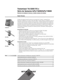
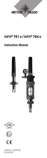
InFit ® <strong>761</strong> e/InFit ® <strong>764</strong> e<br />
Instruction Manual<br />
InFit ® <strong>761</strong> / InFit ® <strong>764</strong><br />
52 403 547
2 InFit ® 76X e Series<br />
© It is forbidden to reprint this Instruction Manual in<br />
whole or part. No part of this manual may be repro duced<br />
in any form, or modified, copied or distributed using<br />
electronic systems, in particular in the form of photo -<br />
copies, photographs, magnetic or other recordings,<br />
without written consent of Mettler-Toledo GmbH, Process<br />
Analytics, CH-8902 Urdorf, Switzerland.<br />
All rights reserved, in particular reproduction, trans -<br />
lation and patenting/registration.<br />
© 07 / 12 Mettler-Toledo GmbH, CH - 8606 Greifensee<br />
Printed in Switzerland 52 403 547
InFit ® 76X e Series 3<br />
InFit ® <strong>761</strong> e/InFit ® <strong>764</strong> e<br />
Instruction Manual<br />
© 07 / 12 Mettler-Toledo GmbH, CH - 8606 Greifensee<br />
Printed in Switzerland 52 403 547
4 InFit ® 76X e Series<br />
How to use this<br />
Instruction Manual<br />
This Instruction Manual is an integral part of<br />
the <strong>METTLER</strong> <strong>TOLEDO</strong> insertion housing<br />
InFit 76X e Series and contains notes and<br />
instructions that are important for safety and<br />
operation.<br />
All persons working on or with the InFit 76X e<br />
must have first read and understood the<br />
sections appropriate to the work in hand.<br />
Please read this Instruction Manual carefully<br />
before using the housing. Keep this document<br />
close to the unit, so that operating personnel<br />
may easily be able to refer to it at any time.<br />
Caution! Please first read Section 1 «Intro -<br />
duction» and Section 2 «Safety instruc tions».<br />
Proprietary designations<br />
The following are proprietary names and, for<br />
the sake of simplicity, will be mentioned in this<br />
Instruction Manual without the registration<br />
marking, e.g.<br />
– InFit ® is a registered trade mark of Mettler-<br />
Toledo GmbH, CH-8606 Greifensee,<br />
Switzerland.<br />
– PTFE, Viton ® and Kalrez ® are regis tered<br />
trademarks of DuPont.<br />
Use of warnings and symbols<br />
Danger! Warning of a dangerous situation that<br />
can lead to death or severe injury, or cause<br />
extensive material damage.<br />
Caution! Warning of a possibly dangerous<br />
situation that can lead to light bodily harm<br />
and/or material damage.<br />
Attention: Information referring to technical<br />
requirements. Non-adherence can lead to<br />
malfunction, uneconomic working and<br />
possibly also to loss of productivity.<br />
© 07 / 12 Mettler-Toledo GmbH, CH - 8606 Greifensee<br />
Printed in Switzerland 52 403 547
InFit ® 76X e Series 5<br />
Explanation of housing designations<br />
The generic term InFit 76X e Series used in this<br />
Instruction Manual refers to:<br />
– InFit <strong>761</strong> e – Insertion housing for pH/<br />
Redox electrodes with gel-type or polymer<br />
electrolyte, O 2 , CO 2 , turbidity and con -<br />
ductivity sensors (with 12 mm diameter<br />
and Pg 13.5 thread).<br />
– InFit <strong>764</strong> e – Insertion housing for pressurized<br />
pH/Redox electrodes with liquid<br />
electrolyte (such as InPro 2000).<br />
© 07 / 12 Mettler-Toledo GmbH, CH - 8606 Greifensee<br />
Printed in Switzerland 52 403 547
6 InFit ® 76X e Series<br />
Contents<br />
1 Introduction ....................................................8<br />
1.1 Ex declaration ..................................................9<br />
1.1.1 Use in Ex classified areas (hazardous areas) ......9<br />
1.1.2 Ex classification II 1/2GD IIC T6/T5/T4/T3<br />
IP6X T 69 °C / T 81 °C / T 109 °C / T 161 °C<br />
in accordance with EC Type Examination<br />
certification SNCH 03 ATEX 3590 X ....................9<br />
1.2 FM certification ..............................................11<br />
1.2.1 Ex classification «FM Approved» ......................12<br />
2 Safety ..........................................................13<br />
2.1 Introduction ....................................................13<br />
2.2 Declaration of conformity/type examinations ......14<br />
2.3 Type examination in accordance with<br />
directive 97/23/EC ..........................................16<br />
2.3.1 Type examination (Module B) in accordance<br />
with directive 97/23/EC ..................................16<br />
2.3.2 Type conformity (Module C1) in accordance<br />
with directive 97/23/EC ..................................16<br />
2.4 EC type examination certification in<br />
accordance with directive 94/9/EC ....................17<br />
2.5 FM certificate ..................................................18<br />
2.6 Housing designations......................................22<br />
2.7 Intended use ..................................................23<br />
2.8 Inappropriate use ............................................23<br />
2.9 Basic principles ..............................................24<br />
2.10 Warning notices and symbols ..........................24<br />
2.11 Responsibilities, organizational measures..........25<br />
2.11.1 Responsibilities of the operator ........................25<br />
2.11.2 Responsibilities of the personnel ......................25<br />
2.11.3 Selection and qualification of personnel –<br />
basic duties....................................................26<br />
2.12 Product-specific hazards..................................26<br />
2.12.1 Removal of electrode/sensor ............................26<br />
2.12.2 Manipulation and maintenance work<br />
on the housings..............................................27<br />
2.12.3 Plastic housings ............................................27<br />
2.12.4 Installation in pressurized systems....................28<br />
2.12.5 Installation in potentially explosive<br />
areas (hazardous areas) ................................28<br />
2.13 Residual hazards ............................................29<br />
2.13.1 Leaky connections ..........................................29<br />
2.13.2 Medium residues ............................................29<br />
2.13.3 Heat protection ..............................................29<br />
2.13.4 External impacts ............................................30<br />
2.14 Emergency measures ......................................30<br />
2.15 Safety measures ............................................30<br />
2.16 Modifications ................................................31<br />
3 Product description ......................................32<br />
3.1 Scope of delivery ............................................32<br />
3.2 Packing ........................................................32<br />
3.3 Checking the shipment ....................................32<br />
3.4 Product overview ............................................33<br />
Product key ....................................................42<br />
3.5 Functional description of the housing ................44<br />
© 07 / 12 Mettler-Toledo GmbH, CH - 8606 Greifensee<br />
Printed in Switzerland 52 403 547
InFit ® 76X e Series 7<br />
4 Installation and start-up ................................45<br />
4.1 Preparation of the equipment............................45<br />
4.2 Fitting and installation work..............................47<br />
4.2.1 Fitting the housing ..........................................47<br />
4.2.1.1 Fitting with a weld-in socket ............................47<br />
4.2.1.2 Fitting with a flange ........................................48<br />
4.2.1.3 Fitting via NPT external thread ..........................48<br />
4.2.1.4 Fitting with Tri-Clamp and<br />
Varivent flange connection ..............................48<br />
4.2.1.5 Installation with NPSM thread ..........................49<br />
4.2.2 Fitting the electrode/sensor ..............................49<br />
4.2.2.1 InFit <strong>761</strong> e ....................................................49<br />
4.2.2.2 InFit <strong>764</strong> e......................................................51<br />
4.3 Startup procedures for housings........................53<br />
4.4 Dismantling work ..........................................54<br />
4.4.1 Removing the insertion housing........................54<br />
4.4.2 Removing the electrode/sensor ........................54<br />
4.5 Sterilization ..................................................57<br />
5 Operation ......................................................58<br />
5.1 Important information for everyday operation......58<br />
5.2 Inspection work in everyday operation ..............58<br />
5.3 Cleaning the electrode/sensor ..........................59<br />
5.4 Calibrating the measuring system ....................59<br />
6 Maintenance..................................................60<br />
6.1 Important information on maintenance ..............60<br />
6.2 Topping up reference electrolyte ........................61<br />
6.3 Replacement of medium-wetted seals................61<br />
7 Trouble shooting ............................................64<br />
8 Product specifications ....................................66<br />
8.1 Technical data ................................................66<br />
8.1.1 Technical specifications InFit <strong>761</strong> e ..................66<br />
8.1.2 Technical specifications InFit <strong>764</strong> e ..................68<br />
8.2 Spare parts and accessories ............................70<br />
9 Terms of warranty ..........................................74<br />
10 Decommissioning, storage, disposal ..............75<br />
10.1 Decommissioning ..........................................75<br />
10.1.1 Proceed as described in Section 4.4<br />
«Dismantling work».........................................75<br />
10.1.2 Repair............................................................75<br />
10.2 Storage ........................................................75<br />
10.3 Disposal ......................................................76<br />
11 Appendices....................................................77<br />
11.1 Electrode/sensor selection ................................77<br />
© 07 / 12 Mettler-Toledo GmbH, CH - 8606 Greifensee<br />
Printed in Switzerland 52 403 547
8 InFit ® 76X e Series<br />
1 Introduction<br />
– The insertion housing InFit 76X e is safe to<br />
operate and has been tested by <strong>METTLER</strong><br />
<strong>TOLEDO</strong> and dispatched ready for in -<br />
stallation.<br />
– Before starting to use the housing, care -<br />
fully read this Instruction Manual: the<br />
safety precautions and warnings con -<br />
tained in it must be observed.<br />
In addition to this Instruction Manual please<br />
also note the following:<br />
– All local safety regulations.<br />
– All instructions and warning remarks in the<br />
publications of the products that are used<br />
in conjunction with the insertion housing<br />
(electrodes, sensors, etc.).<br />
– All safety precautions for the plant into<br />
which the housing InFit 76X e will be<br />
in stalled.<br />
– All instructions and warnings labelled on<br />
the housing InFit 76X e.<br />
– All safety information relative to operation<br />
in potentially explosive atmosphere/<br />
hazardous areas (Ex classified zones).<br />
© 07 / 12 Mettler-Toledo GmbH, CH - 8606 Greifensee<br />
Printed in Switzerland 52 403 547
InFit ® 76X e Series 9<br />
1.1 Ex declaration<br />
1.1.1 Use in Ex classified areas<br />
(hazardous areas)<br />
Caution! For intended installation in an Ex<br />
classified area, please observe the following<br />
guidelines (ATEX 94/9/EC). The Ex declaration<br />
is only valid for housings with mediumwetted<br />
parts made of metallic material.<br />
– Ex classification: II 1/2GD IIC T6/T5/<br />
T4/T3 IP6X T 69 °C/T 81 °C/T 109 °C/<br />
T 161 °C<br />
– Designation and number of certificate:<br />
SNCH 03 ATEX 3590 X<br />
1.1.2 Ex classification II 1/2GD IIC T6/ T5/<br />
T4/T3 IP6X T 69°C/T 81 °C/T 109°C/<br />
T 161°C in accordance with EC Type<br />
Examination certification SNCH<br />
03 ATEX 3590 X<br />
According to RL 94/9/EG (ATEX 95) Appendix l,<br />
InFit 76X/*1*2/*3/*4/*5/*6*7*8 housings<br />
are devices group ll, category 1/2G and according<br />
to RL 99/92/EG (ATEX 137) may be<br />
used in zones 0/1 or 0/2 and gas groups llA,<br />
llB and llC that are potentially explosive due to<br />
combustible substances in the temperatures<br />
classes T1 to T6.<br />
For use/installation, the requirements of<br />
EN 60079-14 must be observed.<br />
According to RL 94/9/EG (ATEX 95) Appendix l,<br />
InFit 76X/*1*2/*3/*4/*5/*6*7*8 housings<br />
are devices group ll, category 1/2D and<br />
according to RL 99/92/EG (ATEX 137) may<br />
also be used in zones 20/21 resp. 20/22 that<br />
contain combustible dusts.<br />
For use/installation, the requirements of<br />
EN 50281-1-2 must be observed.<br />
© 07 / 12 Mettler-Toledo GmbH, CH - 8606 Greifensee<br />
Printed in Switzerland 52 403 547
10 InFit ® 76X e Series<br />
Special conditions X<br />
1. The maximum permissible environment<br />
resp. process temperatures for the zone 0<br />
(combustible gases or combustible liquids)<br />
are in accordance with the temperature<br />
classes shown in the table below:<br />
Temperature Max. environment resp.<br />
class process temperature<br />
T6 68 °C<br />
T5 80 °C<br />
T4 108 °C<br />
T3 160 °C<br />
The maximum permissible environment<br />
resp. process temperatures may not<br />
exceed the above mentioned values. Full<br />
details are to be found in the Instruction<br />
Manual, «Section 8».<br />
2. The maximum surface temperatures for the<br />
zone 20 (combustible dusts) are in accordance<br />
with the environment resp. process<br />
temperatures shown in the table below:<br />
Surface Max. environment resp.<br />
temperature process temperature<br />
T 69 °C 68 °C<br />
T 81 °C 80 °C<br />
T 109 °C 108 °C<br />
T 161 °C 160 °C<br />
The maximum permissible environment<br />
resp. process temperatures may not<br />
exceed the above mentioned values. Full<br />
details are to be found in the Instruction<br />
Manual, «Section 8».<br />
3. The metal body of the housings Type InFit<br />
76X/*1*2/*3/*4/*5/*6*7*8 must be<br />
electrically connected to the potential<br />
equalizing system of the installation.<br />
4. The metal body of the housings Type<br />
InFit 76X/*1*2/*3/*4/*5/*6*7*8 are, if<br />
necessary, to be included into the periodic<br />
pressure test of the unit.<br />
Please refer to the «Declaration of conformity»<br />
on page 14 and 15 for detailed explanation of<br />
the product key.<br />
© 07 / 12 Mettler-Toledo GmbH, CH - 8606 Greifensee<br />
Printed in Switzerland 52 403 547
InFit ® 76X e Series 11<br />
1.2 FM certification<br />
Caution! For intended installation in an Ex<br />
classified area, please observe the following<br />
guidelines. The Ex declaration is valid only for<br />
housings with medium-wetted parts made of<br />
metallic material.<br />
– Ex classification:<br />
IS CL I,II,III, Div 1, GR ABCDEFG/T6 1)<br />
1) Intrinsically safe, with Entity parameters, for use<br />
in Class I,II,III, Division 1, Groups A, B, C, D, E,<br />
F and G hazardous (classified) locations in accordance<br />
with manufacturer’s control drawing<br />
no. 53 800 002.<br />
– Designation and number of the decla -<br />
ration: Original project ID 3021227<br />
(Note the drawing on the following page,<br />
«Section 1.2.1»)<br />
© 07 / 12 Mettler-Toledo GmbH, CH - 8606 Greifensee<br />
Printed in Switzerland 52 403 547
12 InFit ® 76X e Series<br />
1.2.1 Ex classification «FM Approved»<br />
(drawing)<br />
Non-Hazardous Location Hazardous (Classified) Location<br />
Any FMRC Approved Single<br />
Multi-Channel Barrier or Apparatus<br />
Class I, Division 1, Groups A, B, C and D<br />
Class II, Division 1, Groups E, F and G<br />
Class III, Division 1<br />
T6 Ta=60°C<br />
Notes:<br />
Entity Parameters:<br />
Vt=15V, It=30 mA, Pmax=0.25W<br />
Ci=0.1 µF, Li=0 mH<br />
1. No revision to this drawing is permitted without FMRC approval<br />
2. Vmax > Vt; Imax > It; (Ci of all loops + C cable) < Ca; (Li of all loops + L cable) < La; Pmax or Pi > P0<br />
3. Single Multi-Channel IS Barrier or Apparatus must be FMRC Approved<br />
4. Single Multi-Channel IS Barrier or Apparatus manufacturer's control drawings<br />
must be followed when installing the System. IS Barrier or Equipment may be<br />
installed within the Hazardous (Classified) location for which it is approved.<br />
5. Installation must be in accordance with Article 500 of the NEC ® (ANSI/NFPA 70)<br />
and ANSI/ISA RP12.6.<br />
WARNING: substitution of components may inpair intrinsic safety.<br />
Probe Mettler-Toledo GmbH<br />
Process Analytics<br />
CH-8902 Urdorf<br />
Wir behalten uns alle Rechte an diesem Dokument und an allen Beilagen vor. Der Empfänger anerkennt<br />
diese Rechte und wird die genannten Unterlagen nicht ohne unsere vorgängige schriftliche Ermächtigung<br />
Dritten zugänglich machen oder ausserhalb des Zweckes verwenden, zu dem sie ihm übergeben worden sind.<br />
© 07 / 12 Mettler-Toledo GmbH, CH - 8606 Greifensee<br />
Printed in Switzerland 52 403 547
InFit ® 76X e Series 13<br />
2 Safety<br />
2.1 Introduction<br />
The Instruction Manual contains the most<br />
important information for using the InFit 76X e<br />
housings efficiently and in accordance with<br />
regulations. A basic condition for safe handling<br />
and operation without malfunctions is the<br />
knowledge of these safety instructions and the<br />
observance of the further warnings in the<br />
Instruction Manual.<br />
This Instruction Manual, and in particular the<br />
safety regulations, are intended for personnel<br />
entrusted with the operation and maintenance<br />
of the housings. It is assumed that these<br />
persons are familiar with the equipment in<br />
which the housing is installed. Therefore,<br />
before any work is started with the housing,<br />
this Instruction Manual must be read and<br />
understood by those persons involved.<br />
The Instruction Manual must be stored where<br />
it is constantly accessible and available to any<br />
person working with the InFit 76X e housing.<br />
On receipt of the shipment, check imme dia tely:<br />
– the housing and accessories for any sign<br />
of transport damage. Report any damage<br />
immediately to the carrier and to your<br />
supplier.<br />
– the type designation on the housing body.<br />
– for completeness of the supply. Please<br />
notify your supplier immediately if the<br />
shipment is incomplete or in any way<br />
incorrect (see Section 3.1 «Scope of<br />
delivery»).<br />
© 07 / 12 Mettler-Toledo GmbH, CH - 8606 Greifensee<br />
Printed in Switzerland 52 403 547
14 InFit ® 76X e Series<br />
2.2 Declaration of conformity/<br />
type examinations<br />
Attention: The «Declarations of Conformity<br />
and Type Examinations» are dependent on the<br />
design and the individual type of housing, and<br />
have no general validity for the complete InFit<br />
product range.<br />
Declarations of conformity and certificates<br />
specific to particular products are available for<br />
download in PDF format in the Product Info<br />
Section of our Internet website (direct access<br />
available via: www.mtpro.com/Service).<br />
1. Housings with CE marking with Notified<br />
Body according to PED directives (Cat. 1<br />
and Cat. 3) and Ex directives: mediumwetted<br />
parts made of metallic material<br />
> DN25<br />
2. Housings with CE marking with Notified<br />
Body according to EX directives: mediumwetted<br />
parts made of metallic material<br />
≤ DN25<br />
3. Housings with CE marking without Notified<br />
Body according to PED directives (Cat. 1):<br />
medium-wetted parts made of plastic<br />
≤ DN25.<br />
4. Housings without CE marking: mediumwetted<br />
parts made of plastic ≤ DN25<br />
Example of a declaration of conformity:<br />
© 07 / 12 Mettler-Toledo GmbH, CH - 8606 Greifensee<br />
Printed in Switzerland 52 403 547
InFit ® 76X e Series 15<br />
© 07 / 12 Mettler-Toledo GmbH, CH - 8606 Greifensee<br />
Printed in Switzerland 52 403 547
16 InFit ® 76X e Series<br />
2.3 Type examination in<br />
accordance with directive<br />
97/23/EC<br />
2.3.1 Type examination (Module B) in<br />
accordance with directive 97/23/EC<br />
2.3.2 Type conformity (Module C1) in<br />
accordance with directive 97/23/EC<br />
© 07 / 12 Mettler-Toledo GmbH, CH - 8606 Greifensee<br />
Printed in Switzerland 52 403 547
InFit ® 76X e Series 17<br />
2.4 EC type examination<br />
certification in accordance<br />
with directive 94/9/EC<br />
Certificate according to ATEX (page 1 of 2)<br />
Certificate according to ATEX (page 2 of 2)<br />
© 07 / 12 Mettler-Toledo GmbH, CH - 8606 Greifensee<br />
Printed in Switzerland 52 403 547
18 InFit ® 76X e Series<br />
2.5 FM certificate<br />
FM certificate (page 1 of 7):<br />
FM certificate (page 2 of 7):<br />
© 07 / 12 Mettler-Toledo GmbH, CH - 8606 Greifensee<br />
Printed in Switzerland 52 403 547
InFit ® 76X e Series 19<br />
FM certificate (page 3 of 7):<br />
FM certificate (page 4 of 7):<br />
© 07 / 12 Mettler-Toledo GmbH, CH - 8606 Greifensee<br />
Printed in Switzerland 52 403 547
20 InFit ® 76X e Series<br />
FM certificate (page 5 of 7):<br />
FM certificate (page 6 of 7):<br />
© 07 / 12 Mettler-Toledo GmbH, CH - 8606 Greifensee<br />
Printed in Switzerland 52 403 547
InFit ® 76X e Series 21<br />
FM certificate (page 7 of 7):<br />
© 07 / 12 Mettler-Toledo GmbH, CH - 8606 Greifensee<br />
Printed in Switzerland 52 403 547
22 InFit ® 76X e Series<br />
2.6 Housing designations<br />
Housing designation as well as part and<br />
serial numbers can be noted from the type<br />
plate and used for clear identification when<br />
communicating with the manufacturer.<br />
Attention: The specifications shown on the<br />
type plate are dependent on the design and the<br />
individual type of housing and have no<br />
general validity for the complete InFit product<br />
range.<br />
Label type 1:<br />
Type plate in accordance with Ex directive<br />
and PED directive 97/23/EC Cat. 3 + Cat. 1<br />
Label type 2:<br />
Type plate for Ex housings in accordance<br />
with Ex directive<br />
Label type 3:<br />
Type plate for non-Ex housings in accordance<br />
with PED directive 97/23/EC Cat. 1<br />
Label type 4:<br />
Type plate for non-Ex housings in<br />
accordance with PED directive 97/23/EC<br />
(art. 3, paragraph 3)<br />
Label is used in combination<br />
with label type 1 or 2<br />
Label is used in combination<br />
with label type 3 or 4<br />
© 07 / 12 Mettler-Toledo GmbH, CH - 8606 Greifensee<br />
Printed in Switzerland 52 403 547
InFit ® 76X e Series 23<br />
2.7 Intended use<br />
The insertion housings InFit 76X e are intended<br />
solely for measurement tasks in conjunction<br />
with the specified <strong>METTLER</strong> <strong>TOLEDO</strong> electrodes/sensors,<br />
namely pH and Redox (ORP)<br />
combination electrodes as well as oxygen,<br />
CO 2 , conductivity or turbidity sensors. Use the<br />
housings only for this purpose.<br />
Housings with the symbol on the type<br />
plate have received approval for operation in<br />
potentially explosive/hazardous areas (see<br />
«Section 1.1»).<br />
The following are also part of the stipulations<br />
for the correct and appropriate use of the<br />
housings:<br />
– Compliance with the instructions, regu -<br />
lations and information contained in this<br />
Instruction Manual.<br />
– Adherence to the prescribed inspection and<br />
maintenance/servicing intervals.<br />
– Correct maintenance of the housings.<br />
– Operation in compliance with prevailing<br />
regulations concerning the environmental<br />
and operating conditions as well as with<br />
the admissible mounting positions.<br />
– Observance of local legislation.<br />
Danger! The housing must be operated only<br />
with the specified electrodes/sensors. The<br />
absence or the installation of an inappropriate<br />
electrode/sensor may adversely affect the<br />
resistance to pressure and temperature, the<br />
chemical resistance and the protection against<br />
explosion. Consequently, there can be<br />
leakage from the housing and/or risk of ex -<br />
plosion that may endanger persons and the<br />
en vironment.<br />
2.8 Inappropriate use<br />
Any utilization other than the above mentioned,<br />
as well as any utilization that is not consistent<br />
with the technical data is taken as being<br />
not in conformance with regulations. The operator<br />
bears the sole risk for any damage caused<br />
by such utilization.<br />
© 07 / 12 Mettler-Toledo GmbH, CH - 8606 Greifensee<br />
Printed in Switzerland 52 403 547
24 InFit ® 76X e Series<br />
2.9 Basic principles<br />
The insertion housing InFit 76X e is built in<br />
accordance with state-of-the-art technology<br />
and recognized technical safety regulations.<br />
However, the housing can be a source of risk<br />
and danger:<br />
– if the housing is operated by insufficiently<br />
trained persons.<br />
– if the housing is not used in compliance<br />
with regulations and/or stipulations for<br />
appropriate use.<br />
InFit 76X e housings must be used only in<br />
perfect technical condition and for the purpose<br />
intended by the manufacturer. It is assumed<br />
that the user is fully aware of safety/danger<br />
issues and respects the Instruction Manual<br />
and all local safety regulations.<br />
Malfunction and damage that can affect<br />
safety and function of the housing must im -<br />
mediately be remedied by the operator or an<br />
expert, and notified to the manufacturer in<br />
writing!<br />
Danger! Defective insertion housings must<br />
neither be installed nor put into operation.<br />
Leakage and inappropriate installation may<br />
lead to the escape of medium or to pressure<br />
surges (explosion), potentially harmful both to<br />
persons and to the environment.<br />
2.10 Warning notices and<br />
symbols<br />
The following symbols are used in this Instruction<br />
Manual to mark safety instructions:<br />
Danger! Warning of a dangerous situation that<br />
can lead to death or severe injury, or cause<br />
extensive material damage.<br />
Caution! Warning of a possibly dangerous<br />
situation that can lead to light bodily harm<br />
and/or material damage.<br />
Attention: Information referring to technical<br />
requirements. Non-adherence can lead to<br />
malfunction, uneconomic working and possibly<br />
also to loss of productivity.<br />
© 07 / 12 Mettler-Toledo GmbH, CH - 8606 Greifensee<br />
Printed in Switzerland 52 403 547
InFit ® 76X e Series 25<br />
2.11 Responsibilities,<br />
organizational measures<br />
2.11.1 Responsibilities of the operator<br />
– The operator must restrict permission to<br />
work with InFit 76X e insertion housings to<br />
persons who are familiar with the basic<br />
requirements of work safety and accident<br />
prevention, and who have been instructed<br />
in the handling of the housing. This Instruction<br />
Manual serves as the basic document.<br />
– In addition to the Instruction Manual there<br />
are also generally applicable legal and<br />
other binding regulations for work safety<br />
and accident prevention as well as for<br />
environmental protection, and these must<br />
be provided by the operator and instructed<br />
to personnel using the housings.<br />
– The operator/user must periodically check<br />
that the personnel is fully aware of regu -<br />
lations on safety and risk prevention.<br />
– Measures must be taken to ensure that the<br />
insertion housings are only operated in a<br />
safe and fully functional condition.<br />
– If the housings are employed in hazardous<br />
areas, compliance with prevailing regu -<br />
lations must be ensured.<br />
Caution! Before the insertion housing is put<br />
into operation, the operator has to make sure<br />
that use of the housing in conjunction with the<br />
other associated equipment and resources is<br />
fully authorized.<br />
2.11.2 Responsibilities of the personnel<br />
– All persons operating the insertion<br />
housings must have read Sections 1<br />
«Introduction» and 2 «Safety» as well as<br />
the warning notices in this Instruction<br />
Manual.<br />
– In addition to the Instruction Manual,<br />
generally applicable legal and other<br />
binding regulations for work safety and<br />
accident prevention must be adhered to.<br />
– Avoid any kind of working that is doubtful<br />
from a safety perspective or which exceeds<br />
the admissible scope of use.<br />
– Do not use high-pressure cleaning<br />
equipment for polymer/plastic com -<br />
ponents of the housing.<br />
© 07 / 12 Mettler-Toledo GmbH, CH - 8606 Greifensee<br />
Printed in Switzerland 52 403 547
26 InFit ® 76X e Series<br />
Attention: Before every start-up, the insertion<br />
housing must be checked for:<br />
– damage to the connections, fastenings,<br />
etc.<br />
– leakage<br />
– proper functioning<br />
– authorization for use in conjunction with<br />
other plant equipment and resources.<br />
Danger! Defective insertion housings must<br />
neither be installed nor put into operation.<br />
Leakage and inappropriate installation may<br />
lead to the escape of medium or to pressure<br />
surges (explosion), potentially harmful both to<br />
persons and to the environment.<br />
2.11.3 Selection and qualification of<br />
personnel – basic duties<br />
– Work on or with the insertion housings<br />
may only be carried out by authorized and<br />
appropriately trained or instructed per -<br />
sonnel. The personnel must have read this<br />
Instruction Manual in advance.<br />
– Clear responsibilities must be established<br />
for the personnel entrusted with operation,<br />
service, repair, etc. of the housings.<br />
– It must be ensured that only specifically<br />
assigned personnel may operate the<br />
housings.<br />
Danger! Incorrect manipulation or operation of<br />
the housings or non-observance of safety<br />
regulations can lead to malfunction of the<br />
housing and to the escape of process<br />
medium, thus presenting a potential hazard to<br />
the environment, personnel and material.<br />
2.12 Product-specific hazards<br />
2.12.1 Removal of electrode/sensor<br />
Danger! The electrode or sensor must be<br />
removed only after the piping/vessel has been<br />
depressurized and emptied. Otherwise, the<br />
removed electrode/sensor may cause the<br />
process medium to escape thus presenting a<br />
severe danger to persons, material and the<br />
environment. Any toxic or aggressive medium<br />
may cause severe poisoning or causticization.<br />
© 07 / 12 Mettler-Toledo GmbH, CH - 8606 Greifensee<br />
Printed in Switzerland 52 403 547
InFit ® 76X e Series 27<br />
Note: Any broken sensor or defective/cut<br />
O-ring must be replaced without delay.<br />
Danger! Broken sensors prevent accurate<br />
measurings and thus adversely affect process<br />
safety.<br />
2.12.2 Manipulation and maintenance work<br />
on the housings<br />
Attention: Before dismantling an insertion<br />
housing or commencing any maintenance<br />
work on it, ensure that the equipment in which<br />
the insertion housing is installed is in a safe<br />
condition (depressurized, explosion-proof,<br />
emptied, rinsed, vented, etc.). Insertion<br />
housings may only be stripped down after<br />
having been completely dismounted.<br />
Manipulation of the sensor and the housing<br />
may only take place after it is has been<br />
ensured that no process medium can escape<br />
through the housing in the event of incorrect<br />
manipulation. For this reason, the complete<br />
system must be emptied and vented in<br />
advance (safe condition).<br />
It is mandatory to wear personal protective<br />
outfit such as protective goggles and clothing.<br />
Only maintenance and repair work specified in<br />
this Instruction Manual may be performed on<br />
the insertion housing.<br />
Exclusively use genuine spare parts from<br />
<strong>METTLER</strong> <strong>TOLEDO</strong> when replacing defective<br />
components (see Section 8.2 «Spare parts<br />
and accessories»).<br />
Danger! Non-compliance with the prescribed<br />
maintenance instructions may endanger<br />
personnel and the environment.<br />
2.12.3 Plastic housings<br />
Attention:<br />
– Insertion housings made of plastic do not<br />
have the same mechanical resistance as<br />
steel housings.<br />
– Insertion housings made of plastic require<br />
more frequent servicing than steel<br />
housings.<br />
– Defective components may be replaced by<br />
an authorized service center only.<br />
© 07 / 12 Mettler-Toledo GmbH, CH - 8606 Greifensee<br />
Printed in Switzerland 52 403 547
28 InFit ® 76X e Series<br />
Danger! Plastic housings may not be used in<br />
applications subject to high mechanical stress<br />
as this could break the protective cage.<br />
2.12.4 Installation in pressurized systems<br />
Attention: The specified maximum tempe -<br />
rature and pressure must not be exceeded. The<br />
respective specifications depend on the design<br />
and type of housing and are given on the<br />
individual type plates.<br />
Danger! If temperature and pressure limits are<br />
exceeded, there is a risk to the integrity of the<br />
system, thus presenting a potential threat to<br />
human life and to the environment.<br />
Attention: Ample specifications of maximum<br />
admissible temperature and pressure are<br />
given in «Section 8».<br />
2.12.5 Installation in potentially explosive<br />
areas (hazardous areas)<br />
Attention:<br />
– It should be considered to include the<br />
<strong>METTLER</strong> <strong>TOLEDO</strong> insertion housing<br />
InFit 76X e and the process connections in<br />
your recurring pressure test program for the<br />
complete plant as a whole.<br />
– The operator must ensure that the housing<br />
can be used safely in conjunction with<br />
other associated plant resources.<br />
– The insertion housing and the process<br />
connections must be connected to the<br />
main potential equalization system of the<br />
plant (see drawing below).<br />
A<br />
B<br />
C<br />
Erdung / Grounding /<br />
Mise à terre<br />
D<br />
Connection of the housing to the potential<br />
equalization system of the plant.<br />
© 07 / 12 Mettler-Toledo GmbH, CH - 8606 Greifensee<br />
Printed in Switzerland 52 403 547
InFit ® 76X e Series 29<br />
A: Installation from top<br />
InFit <strong>761</strong>/NY/*/*/P01/*/2-<br />
B: Installation from top<br />
InFit <strong>761</strong>/NY/*/*/P02/*/--<br />
C: Lateral installation<br />
InFit <strong>761</strong>/WS/*/*/D00/*/9-<br />
D: Installation in piping<br />
InFit <strong>761</strong>/NS/*/*/D00/*/9-<br />
Danger! Non-observance of legal regulations<br />
concerning use in hazardous areas can<br />
endanger human life and the environment.<br />
2.13 Residual hazards<br />
Attention: Despite all precautionary measures<br />
taken, residual hazards still remain.<br />
2.13.1 Leaky connections<br />
– Connections can become loose through<br />
the effects of vibration.<br />
– The connection between housing and<br />
process adaptor is a potential source of<br />
leakage.<br />
Attention: The connections between the<br />
housing and the process adaptor must be<br />
checked regularly by the customer/operator,<br />
and kept in full working condition.<br />
Danger! Leaky connections can cause the<br />
process medium to escape to the environment,<br />
presenting a hazard for persons and the<br />
environment.<br />
2.13.2 Medium residues<br />
Danger! When retracting/replacing an electrode/sensor,<br />
small quantities of process<br />
medium will remain at the electrode/sensor. If<br />
the medium is a toxic or environmentally<br />
harmful substance, or contains pathogenic<br />
germs, then such contamination must be<br />
removed and disposed of in accordance with<br />
the applicable regulations!<br />
2.13.3 Heat protection<br />
Danger! The housing is not equipped with<br />
heat protection. During steam-sterilization<br />
procedure, the surface of the housing can<br />
reach high temperatures and cause burns.<br />
© 07 / 12 Mettler-Toledo GmbH, CH - 8606 Greifensee<br />
Printed in Switzerland 52 403 547
30 InFit ® 76X e Series<br />
2.13.4 External impacts<br />
Attention: Objects falling on the housing can<br />
damage or destroy the unit, or cause leaks etc.<br />
2.14 Emergency measures<br />
Attention: Always observe and comply with<br />
local regulations!<br />
2.15 Safety measures<br />
Attention: Always observe and comply with<br />
local laws and regulations! These are not an<br />
integral part of this Instruction Manual.<br />
Danger! It is mandatory to wear protective<br />
equipment such as protective goggles and<br />
protective clothing. Aggressive process<br />
medium escaping from the system may be<br />
hazardous to persons or the environment.<br />
Attention: The operator is responsible for the<br />
instruction of personnel. Additional copies of<br />
this Instruction Manual can be ordered from<br />
the equipment supplier. As an integral part of<br />
the insertion housing, this Instruction Manual<br />
must at all times be readily accessible to users<br />
at the point of operation of the housing.<br />
The operator must inform the supplier/manufacturer<br />
of the insertion housing immediately<br />
about any safety-relevant incidents, or ob -<br />
servations made, during use of the housing.<br />
Danger! Incorrect manipulation and/or<br />
instruction errors can lead to potential hazards<br />
for persons and for the environment.<br />
Attention: Before every start-up, the insertion<br />
housing must be checked for:<br />
– damage to the connections, fastenings,<br />
etc.<br />
– leakage<br />
– defective cables and lines etc.<br />
– authorization for use of the housing in<br />
conjunction with the associated plant<br />
resources.<br />
© 07 / 12 Mettler-Toledo GmbH, CH - 8606 Greifensee<br />
Printed in Switzerland 52 403 547
InFit ® 76X e Series 31<br />
Danger! Defective insertion housings must<br />
neither be installed nor put into operation.<br />
Leakage and inappropriate installation may<br />
lead to the escape of medium and cause a<br />
potential threat to life (including the risk of<br />
explosion).<br />
2.16 Modifications<br />
Attention: No attachments or modifications to<br />
the insertion housings are allowed.<br />
Danger! The manufacturer/supplier accepts<br />
no responsibility for any damage caused by<br />
unauthorized attachments and alterations or<br />
for the incorporation of spare parts which are<br />
not of <strong>METTLER</strong> <strong>TOLEDO</strong> provenance. The risk<br />
is borne entirely by the operator.<br />
© 07 / 12 Mettler-Toledo GmbH, CH - 8606 Greifensee<br />
Printed in Switzerland 52 403 547
32 InFit ® 76X e Series<br />
3 Product description<br />
3.1 Scope of delivery<br />
Standard supply of the insertion housing is<br />
made up of the following:<br />
Housing InFit <strong>761</strong> e<br />
– Protective sleeve with antikink protection<br />
– Cable grommet (for 5 mm or 7 mm cable)<br />
– Instruction Manual<br />
– Certificates depending on specifications<br />
Housing InFit <strong>764</strong> e<br />
– Protective sleeve with antikink protection<br />
– Air pump<br />
– Electrolyte recharge syringe<br />
– Pressure connection set<br />
– Cable grommet (for 5 mm or 7 mm cable)<br />
– Instruction Manual<br />
– Certificates depending on specifications<br />
3.2 Packing<br />
The packing consists of cardboard with<br />
protective paddings.<br />
Keep the packing for possible later use, such<br />
as for storage or transport of the housing.<br />
However, if you wish to dispose of the packing,<br />
please observe your local regulations on waste<br />
disposal.<br />
Attention: Also see Section 10.3 «Disposal».<br />
3.3 Checking the shipment<br />
When unpacking the shipment, carefully<br />
examine for signs of damage. Any damage<br />
must be reported to the carrier and your<br />
supplier without delay. Check that the<br />
shipment meets the delivery papers and your<br />
order.<br />
Attention: Damaged housings must not be<br />
installed or put into operation (see «Section<br />
2»).<br />
© 07 / 12 Mettler-Toledo GmbH, CH - 8606 Greifensee<br />
Printed in Switzerland 52 403 547
InFit ® 76X e Series 33<br />
3.4 Product overview<br />
The insertion housings are available in<br />
different versions, based on (refer to the<br />
«Product key» on page 40 and 41):<br />
© 07 / 12 Mettler-Toledo GmbH, CH - 8606 Greifensee<br />
Printed in Switzerland 52 403 547
34 InFit ® 76X e Series<br />
H = Immersion length, a = Sensor length<br />
InFit <strong>761</strong>/WS/*/*/D00/*9-<br />
oder / or / ou<br />
InFit <strong>761</strong>/WS/*/*/D11/*9-<br />
InFit <strong>761</strong>/NS/*/*/D00/*9-<br />
oder / or / ou<br />
InFit <strong>761</strong>/NS/*/*/D11/*9-<br />
I<br />
199<br />
7.834<br />
199<br />
7.834<br />
a=H+50<br />
a=H+1.968<br />
a=H+50<br />
a=H+1.968<br />
60<br />
2.362<br />
60<br />
2.362<br />
G 11/4" G 11/4" G<br />
25<br />
25<br />
0.984<br />
0.984<br />
29<br />
1.141<br />
29<br />
1.141<br />
H-6<br />
H-0.236<br />
O-Ring<br />
20.29 x 2.62<br />
6<br />
0.236<br />
O-Ring<br />
20.29 x 2.62<br />
24<br />
0.944<br />
InFit <strong>761</strong>/WS/*/*/D10/*2-<br />
I<br />
a=H+50<br />
a=H+1.968<br />
199<br />
7.834<br />
60<br />
2.362<br />
G 11/4"<br />
25<br />
0.984<br />
22.4<br />
0.882<br />
M<br />
O-Ring<br />
20.29 x 2.62<br />
6<br />
0.236<br />
Dim. mm<br />
(app.) inch<br />
© 07 / 12 Mettler-Toledo GmbH, CH - 8606 Greifensee<br />
Printed in Switzerland 52 403 547
InFit ® 76X e Series 35<br />
H = Immersion length, a = Sensor length<br />
InFit <strong>761</strong>/NY/*/*/P01/*2-<br />
InFit <strong>761</strong>/WY/*/*/P01/*2-<br />
In<br />
193<br />
7.598<br />
193<br />
7.598<br />
60<br />
2.362<br />
60<br />
2.362<br />
M26x1<br />
22.4<br />
0.882<br />
M26x1<br />
22.4<br />
0.882<br />
a=H+50<br />
a=H+1.968<br />
19<br />
0.748<br />
O-Ring<br />
15.60 x 1.78<br />
a=H+50<br />
a=H+1.968<br />
19<br />
0.748<br />
O-Ring<br />
15.60 x 1.78<br />
*<br />
22<br />
0.866<br />
22<br />
0.866<br />
30<br />
1.181<br />
* For housings with immersion length<br />
H=70 and without protective cage<br />
6<br />
0.236<br />
InFit <strong>761</strong>/NY/*/*/P02/*--<br />
InFit <strong>761</strong>/WY/*/*/P<br />
193<br />
7.598<br />
60<br />
2.362<br />
3/4" R/NPSM<br />
a=H+50<br />
a=H+1.968<br />
19<br />
0.748<br />
Dim. mm<br />
(app.) inch<br />
22<br />
0.866<br />
© 07 / 12 Mettler-Toledo GmbH, CH - 8606 Greifensee<br />
Printed in Switzerland 52 403 547
36 InFit ® 76X e Series<br />
H = Immersion length, a = Sensor length<br />
InFit <strong>761</strong>/WY/*/*/P02/*--<br />
InFit <strong>761</strong>/NY/*/*/N04/*--<br />
oder / or / ou<br />
InFit <strong>761</strong>/NY/*/*/N01/*--<br />
I<br />
3/4" R/NPSM<br />
3/4" NPT<br />
oder<br />
1" NPT<br />
19<br />
0.748<br />
19<br />
0.748<br />
6<br />
0.236<br />
22<br />
0.866<br />
22<br />
0.866<br />
193<br />
7.598<br />
a=H+50<br />
a=H+1.968<br />
a=H+50<br />
a=H+1.968<br />
193<br />
7.598<br />
60<br />
2.362<br />
60<br />
2.362<br />
InFit <strong>761</strong>/WY/*/*/N04/*--<br />
oder / or / ou<br />
InFit <strong>761</strong>/WY/*/*/N01/*--<br />
193<br />
7.598<br />
60<br />
2.362<br />
3/4" NPT<br />
oder<br />
1" NPT<br />
a=H+50<br />
a=H+1.968<br />
19<br />
0.748<br />
22<br />
0.866<br />
6<br />
0.236<br />
Dim. mm<br />
(app.) inch<br />
© 07 / 12 Mettler-Toledo GmbH, CH - 8606 Greifensee<br />
Printed in Switzerland 52 403 547
InFit ® 76X e Series 37<br />
H = Immersion length, a = Sensor length<br />
InFit<strong>761</strong>/NS/*/PVDF/D00/*9-<br />
oder / or / ou<br />
InFit<strong>761</strong>/NS/*/PP/D00/*9-<br />
I<br />
G 1 1/4"<br />
O-Ring<br />
20.29 x 2.62<br />
25<br />
0.984<br />
InFit<strong>761</strong>/WK/0040/*/N04/*--<br />
231<br />
9.094<br />
3/4" NPT<br />
H=ca. 40<br />
H=approx. 2<br />
60<br />
2.362<br />
a=H+50<br />
a=H+1.968<br />
29<br />
1.141<br />
199<br />
7.834<br />
H-6<br />
H-0.236<br />
60<br />
2.362<br />
23<br />
0.905<br />
6<br />
0.236<br />
Dim. mm<br />
(app.) inch<br />
© 07 / 12 Mettler-Toledo GmbH, CH - 8606 Greifensee<br />
Printed in Switzerland 52 403 547
38 InFit ® 76X e Series<br />
H = Immersion length, a = Sensor length<br />
InFit <strong>761</strong>/NC/*/*/D00/*9-<br />
InFit <strong>761</strong>/NC/0025/*/V01/*--<br />
G 1 1/4"<br />
29<br />
1.141<br />
a=H+50<br />
a=H+1.968<br />
a=120<br />
a=4.724<br />
O-Ring<br />
20.29 x 2.62<br />
25<br />
0.984<br />
H-5<br />
H-0.196<br />
25<br />
238<br />
143<br />
5.630<br />
60<br />
2.362<br />
60<br />
25<br />
0.984<br />
68<br />
84<br />
I<br />
InFit <strong>761</strong>/NC/0033/*/V02/*--<br />
a=120<br />
a=4.724<br />
60<br />
2.362<br />
202<br />
7.952<br />
84<br />
3.307<br />
15<br />
52<br />
2.047<br />
33<br />
1.299<br />
Dim. mm<br />
(app.) inch<br />
© 07 / 12 Mettler-Toledo GmbH, CH - 8606 Greifensee<br />
Printed in Switzerland 52 403 547
InFit ® 76X e Series 39<br />
H = Immersion length, a = Sensor length<br />
InFit <strong>761</strong>/NC/*/*/T02/*--<br />
InFit <strong>761</strong>/NC/*/*/T01/*--<br />
2" 1 1/2"<br />
25<br />
0.984<br />
H-5<br />
H-0.197<br />
a=H+50<br />
a=H+1.968<br />
H-5<br />
H-0.197<br />
25<br />
0.984<br />
198<br />
7.795<br />
198<br />
7.795<br />
60<br />
2.362<br />
60<br />
2.362<br />
25<br />
0.984<br />
25<br />
0.984<br />
a=H+50<br />
a=H+1.968<br />
InFit <strong>761</strong>/NC/0033/*/T03/*--<br />
a=120<br />
a=4.724<br />
60<br />
2.362<br />
220<br />
8.661<br />
1 1/2"<br />
15<br />
33<br />
1.299<br />
12.5<br />
0.492<br />
24<br />
0.944<br />
Dim. mm<br />
(app.) inch<br />
© 07 / 12 Mettler-Toledo GmbH, CH - 8606 Greifensee<br />
Printed in Switzerland 52 403 547
40 InFit ® 76X e Series<br />
H = Immersion length, a = Sensor length<br />
InFit<strong>764</strong>/NS/*/*/D11/*4-<br />
oder / or / ou<br />
InFit<strong>764</strong>/NS/*/*/D00/*4-<br />
InFit<strong>764</strong>/WS/*/*/D11/*4-<br />
oder / or / ou<br />
InFit<strong>764</strong>/WS/*/*/D00/*4-<br />
345.5<br />
13.602<br />
345.5<br />
13.602<br />
60<br />
2.362<br />
60<br />
2.362<br />
5<br />
1<br />
1<br />
68<br />
2.677<br />
68<br />
2.677<br />
a=H+50<br />
a=H+1.968<br />
G11/4"<br />
25<br />
0.984<br />
24.5<br />
a=H+50<br />
a=H+1.968<br />
G11/4"<br />
25<br />
0.984<br />
24.5<br />
O-Ring<br />
20.29 x 2.62<br />
26<br />
1.023<br />
O-Ring<br />
20.29 x 2.62<br />
0.197<br />
Form / shape / forme A<br />
Form / shape / forme B<br />
H>=70<br />
H>=2.755<br />
24.5<br />
H>=100<br />
H>=3.937<br />
24.5<br />
1<br />
1<br />
Kein Schutzkorb<br />
No protective cage<br />
Pas de cage de protection<br />
Optionaler Schutzkorb<br />
Optional protective cage<br />
Cage de protection optionelle<br />
• Aufsteckbarer Schutzkorb; nur erhältlich für den unteren Teil Form B<br />
mit der Längen >=100mm<br />
• Plug-type protective cage; available only for lower probes shape B<br />
with lengths >=100mm<br />
• Cage de protection enfichable; seulement disponible pour les formes B<br />
avec longueurs >=100mm<br />
F<br />
Different shapes for the lower part of the<br />
immersion tube.<br />
Dim. mm<br />
(app.) inch<br />
© 07 / 12 Mettler-Toledo GmbH, CH - 8606 Greifensee<br />
Printed in Switzerland 52 403 547
InFit ® 76X e Series 41<br />
H = Immersion length, a = Sensor length<br />
InFit<strong>764</strong>/NC/*/*/D00/*9-<br />
60<br />
2.362<br />
68<br />
2.677<br />
345.5<br />
13.602<br />
F<br />
a=H+50<br />
a=H+1.968<br />
G11/4"<br />
25<br />
0.984<br />
29<br />
1.141<br />
O-Ring<br />
20.29 x 2.62<br />
24<br />
0.944<br />
Form / shape / forme C<br />
Korb<br />
Cage<br />
Cage<br />
Form / shape / forme D<br />
Form / shape / forme E<br />
24.5<br />
24.5<br />
H>=70<br />
H>=2.755<br />
24.5<br />
1<br />
1<br />
1<br />
Aufsteckbarer Schutzkorb; nicht erhältlich für die PVDF-Versionen<br />
Plug-type protective cage; not available for PVDF types<br />
Cage de protection enfichable; ne pas disponible pour les types PVDF<br />
Different shapes for the lower part of the<br />
immersion tube.<br />
Dim. mm<br />
(app.) inch<br />
© 07 / 12 Mettler-Toledo GmbH, CH - 8606 Greifensee<br />
Printed in Switzerland 52 403 547
42 InFit ® 76X e Series<br />
Product key<br />
Immersion length = H, (depending on<br />
Material (wetted<br />
Electrode / sensor type<br />
1 pH/Redox electrodes, O 2 , CO 2 , turbidity and conductivity s<br />
4 pH/Redox electrodes with liquid electrolyte<br />
Protective cage<br />
W Sensor holder with protective cage<br />
N Sensor holder without protective cage<br />
Sensor holder<br />
Y Ø 19 mm shaft<br />
S Ø 25 mm shaft<br />
C Ø 25 mm CIP shaft without protective cage<br />
K NPT shaft<br />
0 0 2 5 25 mm immersion len<br />
0 0 3 3 33 mm immersion len<br />
0 0 4 0 40 mm immersion len<br />
0 0 7 0 70 mm immersion len<br />
0 1 0 0 100 mm immersion le<br />
0 1 5 0 150 mm immersion le<br />
0 1 7 5 175 mm immersion le<br />
0 2 0 0 200 mm immersion le<br />
0 2 7 5 275 mm immersion le<br />
0 3 7 5 375 mm immersion l<br />
4 4 3 5<br />
C 2 2 −<br />
T I − −<br />
P P − −<br />
P V D F<br />
InFit 76 / / /<br />
8 9 10 11 12 13 14 15 16 17 18 19 20 21 2<br />
and for the sensor holder type «C» made of DIN 1.4435 (<br />
1)<br />
Cap nut made of DIN 1.4435 (height = 18), cap nut mad<br />
2)<br />
Hexagon nut made of DIN 1.4305 (height = 18)<br />
3)<br />
Cap nut made of brass (height = 18)<br />
© 07 / 12 Mettler-Toledo GmbH, CH - 8606 Greifensee<br />
Printed in Switzerland 52 403 547
InFit ® 76X e Series 43<br />
ensors (Ø 12 mm and Pg 13.5 thread)<br />
version with/without protective cage ± 5mm)<br />
gth (only for sensor holder type «C»)<br />
gth (only for sensor holder type «C»)<br />
gth<br />
Appropriate sensor lengths<br />
gth<br />
for the immersion lengths,<br />
ngth<br />
please refer to the Section 11<br />
ngth<br />
«Electrode/sensor selection».<br />
ngth<br />
ngth<br />
ngth<br />
ength<br />
parts)<br />
DIN 1.4435<br />
DIN 2.4602/Alloy C22<br />
Titanium<br />
Polypropylene<br />
Polyvinylidene fluoride<br />
Process connections<br />
D 0 0 Ingold DN25 1)<br />
D 1 0 Ingold DN25 2)<br />
D 1 1 Ingold DN25 3)<br />
D 0 4 Flange DN50-PN16 (Ø 25 mm shaft)<br />
P 0 1 Socket DN19 M26x1<br />
P 0 2 3 / 4 " R/NPSM (Ø 19 mm shaft)<br />
P 2 9 Socket DN25 groove pos. 43.6 (type «C»)<br />
N 0 4 NPT 3 / 4 "<br />
N 0 1 NPT 1"<br />
T 0 1 Tri-Clamp flange 1.5" straight<br />
T 0 2 Tri-Clamp flange 2" straight<br />
T 0 3 Tri-Clamp flange 1.5" inclined<br />
V 0 1 Varivent flange DN 50 straight<br />
V 0 2 Varivent flange DN50 inclined<br />
O-ring material<br />
V i FKM Viton ® FDA<br />
E P EPDM FDA<br />
K a FFKM Kalrez ® 6230 FDA/USP Class VI<br />
S i MVQ Silicone FDA/USP Class VI<br />
O-ring position<br />
− no groove<br />
2 22.4 groove distance<br />
4 24.5 groove distance<br />
9 29 groove distance<br />
S Special groove distance<br />
Special<br />
− Standard<br />
S Special<br />
/ /<br />
2 23 24 25 26 27 28 29 30<br />
e of plastic, cap nut for security socket<br />
height = 22)<br />
© 07 / 12 Mettler-Toledo GmbH, CH - 8606 Greifensee<br />
Printed in Switzerland 52 403 547
44 InFit ® 76X e Series<br />
3.5 Functional description of the<br />
housing<br />
The housings act as a support for electrodes<br />
and sensors used in various industries for<br />
measuring pH, Redox, dissolved oxygen,<br />
CO 2 , turbidity and conductivity.<br />
All housings made of steel are suitable for<br />
”in-situ“ sterilization and may be mounted<br />
diagonally or vertically into reactors and<br />
pipings. For sterility reasons the InFit 76X e<br />
with type «C» sensor holder employs an<br />
optimally positioned O-ring to minimize the<br />
gap between the wet part of the housing and<br />
the socket. These versions are especially<br />
designed for advanced hygienic requirements.<br />
For CIP cleaning InFit 76X e versions are<br />
suitable. For autoclaving only InFit <strong>761</strong> e<br />
versions are suitable. In both cases, only<br />
with sensorholder type «C» (see «Product key»<br />
on page 42 and 43). Insertion housings protect<br />
the electrodes/sensors from mechanical<br />
damage. The (black) antistatic protection<br />
sleeve protects the plug-type connector<br />
(allowing easy replacement of electrodes/sensors)<br />
from humidity and mechanical damage.<br />
The plug-type electrodes facilitate electrode interchange<br />
and the electrode cable can be used<br />
repeatedly. Furthermore, most versions<br />
(except the InFit 76X e with type «C» sensor<br />
holder always without protective cage) are<br />
available with or without protective cage for<br />
electrode/sensor tip. The housings with type<br />
«Y» sensor holder are designed for vertical<br />
installation.<br />
Note: Housings suitable for operation in<br />
hazardous areas carry a respective symbol on<br />
their type plate. Housings that do not carry this<br />
additional marking are not admissible for use<br />
in hazardous areas.<br />
All medium wetted parts of the housing are<br />
available in stainless steel according to DIN<br />
1.4435/316L, DIN 2.4602/Alloy C22 or<br />
titanium, or made of PVDF and PP plastics.<br />
The head (top piece) is made of antistatic<br />
PP and nickel-plated brass. The O-ring seals<br />
between the housing and the medium are<br />
made of Viton ® (FKM), Kalrez ® (FFKM),<br />
silicone (MVQ) or EPDM.<br />
© 07 / 12 Mettler-Toledo GmbH, CH - 8606 Greifensee<br />
Printed in Switzerland 52 403 547
InFit ® 76X e Series 45<br />
4 Installation and<br />
start-up<br />
4.1 Preparation of the<br />
equipment<br />
The insertion housings are mounted and fixed<br />
on a vessel (reactor, tank, pipe, etc.) either by<br />
means of a cap nut in conjunction with a weldin<br />
socket, by a flange connection, by a<br />
Tri-Clamp or Varivent adaption or via an<br />
external NPT thread.<br />
Attention: Attachment of the weld-in socket,<br />
flange connection, Tri-Clamp or Varivent<br />
adaption or threaded bushing is the respon -<br />
sibility of the customer.<br />
Attention: Weld-in sockets or safety weld-in<br />
sockets G 1 1 / 4 " (inner Ø = 25 mm, straight<br />
or 15° inclined) made of various material are<br />
available from your supplier.<br />
Danger! Our welding instructions (included in<br />
the supply of the original <strong>METTLER</strong> <strong>TOLEDO</strong><br />
socket) for the weld-in socket must be fully<br />
complied with, as otherwise the process<br />
connection can be untight (leak) or the<br />
pressure resistance insufficient.<br />
Caution! After welding, the bore of the weld-in<br />
socket is to be checked and if necessary<br />
reamed to the dimension 25-H7.<br />
In order to ensure correct function of the in -<br />
sertion housing, please observe the following<br />
installation instructions:<br />
– The insertion housing can be mounted<br />
vertically or in an inclined position. In the<br />
case of inclined mounting, the angle of the<br />
housing must be equal to or greater than<br />
15° above the horizontal.<br />
Caution! Installation outside the admissible<br />
range of mounting positions is not allowed,<br />
otherwise correct operation of the electrodes/<br />
sensors may be impaired.<br />
© 07 / 12 Mettler-Toledo GmbH, CH - 8606 Greifensee<br />
Printed in Switzerland 52 403 547
46 InFit ® 76X e Series<br />
52910536<br />
Admissible mounting position<br />
zulässge Einbaulage<br />
admissible mounting position<br />
positionement de montage admis<br />
unzulässig (ausser für InPro 3100 UD)<br />
inadmissibly (except for InPro 3100 UD<br />
ne pas admissible (excepté pour InPro 3100 UD)<br />
Installation options<br />
– The insertion housing is to be mounted in<br />
such a position that there is always enough<br />
clearance available for its correct functioning<br />
(correct measuring position in the<br />
process medium) as well as for mainte -<br />
nance work (checks, fitting and removal of<br />
the electrodes/sensors or the housing).<br />
The respective dimensions can be found in<br />
the drawings in the appendix to this<br />
Instruction Manual, or in the specifications.<br />
– Installation of the insertion housing in<br />
exposed positions should be avoided. If<br />
this is not possible, appropriate protective<br />
measures against damage or interference<br />
must be taken.<br />
© 07 / 12 Mettler-Toledo GmbH, CH - 8606 Greifensee<br />
Printed in Switzerland 52 403 547
InFit ® 76X e Series 47<br />
4.2 Fitting and installation work<br />
Caution! For all installation work described<br />
below, make sure the equipment in which the<br />
housing is to be installed is in a safe con -<br />
dition (depressurized, emptied, rinsed,<br />
vented, etc.).<br />
4.2.1 Fitting the housing<br />
Caution! Never place the housing on the front<br />
end of the centering spigot or immersion tube<br />
(risk of damage, e.g. damage of the N5<br />
surface). Make sure the housing is fitted to the<br />
designated, appropriate socket or flange as<br />
directed (see «Section 3.5.1»).<br />
4.2.1.1 Fitting with a weld-in socket<br />
1. Clean the centering spigot of the insertion<br />
housing and the bore of the weld-in<br />
socket (25-H7) and check for damage.<br />
Caution! Fitting of the insertion housing<br />
with a damaged spigot or into a damaged<br />
weld-in socket is not allowed and can<br />
present a hazard to persons and/or lead to<br />
material damage.<br />
Caution! Make sure there are no obstacles<br />
in the insertion path that could hamper the<br />
motion of the immersion tube or damage<br />
the sensor/housing.<br />
2. Check the O-ring on the spigot for<br />
damage and replace it if necessary. Sightly<br />
grease the O-ring. Ensure appropriate<br />
quality and positioning of the O-ring.<br />
3. Position the housing on the weld-in socket<br />
and carefully insert the spigot into the bore.<br />
4. Finally, tighten the cap nut until the<br />
connection is completely sealed.<br />
Caution! Checking the sealing/tightness of<br />
the process adaptor is the responsibility of<br />
the operator who must also guarantee<br />
same by adopting appropriate measures.<br />
Additional safety provisions are required if<br />
the connection is subject to stress caused<br />
by vibrations.<br />
© 07 / 12 Mettler-Toledo GmbH, CH - 8606 Greifensee<br />
Printed in Switzerland 52 403 547
48 InFit ® 76X e Series<br />
4.2.1.2 Fitting with a flange<br />
1. Clean the sealing surfaces of the flange<br />
(housing and flange connection on vessel)<br />
and check for damage.<br />
Caution! If the process media/reaction<br />
products are considered to be dangerous,<br />
it is imperative that an embedded seal is<br />
used at the flange interface and/or a splash<br />
guard is mounted. Fitting of the insertion<br />
housing with damaged flange connections<br />
is not allowed and can present a hazard to<br />
persons and/or lead to material damage.<br />
2. Use the appropriate flange gasket and<br />
check for damage. Replace if necessary.<br />
Attention in the case of housings made<br />
of special alloy: Check that the seal is<br />
present on the flange of the insertion housing<br />
and that it is not damaged. Replace if<br />
necessary. Ensure correct quality and<br />
positioning of the seal.<br />
3. Position the housing on the flange connection,<br />
align, and tighten evenly crosswise<br />
using the prescribed number of bolts and<br />
nuts.<br />
4.2.1.3 Fitting via NPT external thread<br />
1. Wind PTFE tape around the external<br />
male thread.<br />
2. Screw the housing carefully into the<br />
female socket.<br />
3. Check the Installation for leaks.<br />
4.2.1.4 Fitting with Tri-Clamp and Varivent flange<br />
connection<br />
1. Clean the sealing surfaces of the flange<br />
(housing and flange connection on vessel)<br />
and check for damage.<br />
Caution! If the process media/reaction<br />
products are considered to be dangerous,<br />
it is imperative that an embedded seal is<br />
used at the flange interface and/or a splash<br />
guard is mounted. Fitting of the insertion<br />
housing with damaged flange connections<br />
is not allowed and can present a hazard to<br />
persons and/or lead to material damage.<br />
Caution! Make sure there are no obstacles<br />
in the insertion path that could hamper the<br />
motion of the immersion tube or damage<br />
the sensor/housing.<br />
2. Use the appropriate flange gasket and<br />
check for damage. Replace if necessary.<br />
© 07 / 12 Mettler-Toledo GmbH, CH - 8606 Greifensee<br />
Printed in Switzerland 52 403 547
InFit ® 76X e Series 49<br />
3. Position the housing on the flange connection,<br />
align, and tighten well with the clamp<br />
fastener.<br />
4.2.1.5 Installation with NPSM thread<br />
1. Carefully screw in the housing from the top.<br />
2. First tighten by hand, then securely tighten<br />
with fork wrench (36 mm size).<br />
3. Check the installation for leaks.<br />
4.2.2 Fitting the electrode/sensor<br />
4.2.2.1 InFit <strong>761</strong> e<br />
Caution! Damaged electrodes/sensors must<br />
never be installed.<br />
Attention: To ensure tightness of the housing<br />
it is mandatory to use the antikink cable gland<br />
«A». In this case, lead the cable from the<br />
bottom through the antikink cable gland «A»<br />
before connecting it to the transmitter.<br />
Attention: If the cable is already in place and<br />
the antikink cable gland «A» is not required<br />
you may lead the cable from the top through<br />
the protective sleeve «C». In this case, the<br />
supplied slotted cable grommet «F» (5 or 7<br />
mm) must be used. However, in this scenario<br />
the tightness of the housing is not ensured.<br />
1. Make sure the white PTFE sliding disk «D»<br />
is located directly below the electrode/<br />
sensor head, with the chamfered part<br />
facing the bottom, followed by the O-ring<br />
«E».<br />
2. Check sliding disk and O-ring for damage<br />
and replace, as required.<br />
3. Remove watering cap from the electrode/ -<br />
sensor tip and rinse electrode/sensor tip<br />
(membrane) with water.<br />
4. Carefully insert the electrode/sensor into<br />
the tube and screw in by hand to the stop.<br />
5. Push cable with connector «B» through<br />
protective sleeve «C».<br />
© 07 / 12 Mettler-Toledo GmbH, CH - 8606 Greifensee<br />
Printed in Switzerland 52 403 547
50 InFit ® 76X e Series<br />
6. Screw connector «B» to pH/Redox electrode<br />
or O 2 sensor. Tighten protective sleeve<br />
«C» on housing by hand.<br />
7. Tighten antikink cable gland «A» or mount<br />
slotted cable grommet «F» to cable and<br />
push into protective sleeve «C».<br />
A<br />
F<br />
B<br />
C<br />
D<br />
E<br />
Fitting of electrode/sensor to InFit <strong>761</strong> e<br />
Attention: The protective sleeve efficiently<br />
guards the plug-type connection between<br />
electrode and cable against dirt, humidity and<br />
mechanical stress. Therefore it is mandatory<br />
to use the protective sleeve for any instal -<br />
lation.<br />
© 07 / 12 Mettler-Toledo GmbH, CH - 8606 Greifensee<br />
Printed in Switzerland 52 403 547
InFit ® 76X e Series 51<br />
4.2.2.2 InFit <strong>764</strong> e<br />
Caution! Damaged electrodes/sensors must<br />
never be installed.<br />
Attention: To ensure tightness of the housing<br />
it is mandatory to use the antikink cable gland<br />
«A». In this case, lead the cable from the<br />
bottom through the antikink cable gland «A»<br />
before connecting it to the transmitter.<br />
Attention: If the cable is already in place and<br />
the antikink cable gland «A» is not required<br />
you may lead the cable from the top through<br />
the protective sleeve «C». In this case, the supplied<br />
slotted cable grommet «F» (5 or 7 mm)<br />
must be used. However, in this scenario the<br />
tightness of the housing is not ensured.<br />
Caution! It is mandatory to follow the sequence<br />
outlined below when fastening the cap nut<br />
«E» and the plastic adapter «D» (see illustration<br />
on page 50), otherwise the pH/Redox<br />
electrode may break.<br />
1. Remove protective sleeve «C», plastic<br />
adapter «D», and finally undo cap nut «E».<br />
2. Make sure you have chosen the appro -<br />
priate type of pH/Redox electrode (see<br />
Section 11 «Appendices»).<br />
3. Remove watering cap from electrode tip,<br />
then undo the filling plug and the rubber<br />
band. Rinse the electrode tip (membrane)<br />
with water. The rubber band must always<br />
be removed before the electrode is fitted.<br />
Danger! Do not tilt the electrode once the<br />
filling plug has been removed as this could<br />
cause the reference electrolyte to drain from<br />
the filling orifice.<br />
4. Check the level of the reference electrolyte<br />
inside the electrode, and top up as re -<br />
quired (see Instruction Manual of the<br />
respective electrode).<br />
5. Carefully insert the electrode into the<br />
immersion tube until it is properly seated<br />
on the PTFE saddle.<br />
Attention: For lateral installation make<br />
sure the marking «Position electrode this<br />
side up» is on top. Assuming the level is<br />
correct, no reference electrolyte can drain<br />
from the filling orifice in this position.<br />
6. Check flat gasket of upper part for damage<br />
and replace, as required. Locate upper<br />
part and fasten the cap nut «E» by hand.<br />
Caution! Cap nut «E» must be fastened<br />
only after the plastic adapter «D» has been<br />
removed.<br />
© 07 / 12 Mettler-Toledo GmbH, CH - 8606 Greifensee<br />
Printed in Switzerland 52 403 547
52 InFit ® 76X e Series<br />
7. Check seal of plastic adapter «D» and<br />
replace, as required. Locate plastic adapter<br />
and tighten by hand.<br />
8. Remove cap of the plug-type connector<br />
from the electrode.<br />
9. Push connector of cable through the<br />
protective sleeve «C» and fasten connector<br />
to plug-type head of the sensor.<br />
10. Mount protective sleeve «C» and tighten by<br />
hand. Secure cable gland «A» or mount<br />
slotted cable grommet «F» to cable and<br />
push into protective sleeve «C».<br />
11. Adjust compensation pressure: The<br />
compensation pressure may be adjusted<br />
at the valve insert of the pressure gauge<br />
using the supplied air pump, or by con -<br />
necting a permanent, oil-free and filtered<br />
pressure supply (use pressure connection<br />
set included in the delivery).<br />
A<br />
F<br />
B<br />
C<br />
D<br />
E<br />
Fitting of electrode/sensor to InFit <strong>764</strong> e<br />
© 07 / 12 Mettler-Toledo GmbH, CH - 8606 Greifensee<br />
Printed in Switzerland 52 403 547
InFit ® 76X e Series 53<br />
Attention: The protective sleeve efficiently<br />
guards the plug-type connection between<br />
electrode and cable against dirt, humidity and<br />
mechanical stress. Therefore it is mandatory<br />
to use the protective sleeve for any instal -<br />
lation.<br />
4.3 Startup procedures for<br />
housings<br />
Attention: Before startup, all fitting and installation<br />
work (see «Section 4.2») must have<br />
been completed!<br />
• Each time before startup, check the<br />
measuring system.<br />
• Inspect the electrode/sensor assembly and<br />
examine housing and system for leaks.<br />
• Do not commence operation until the<br />
measuring system has been checked and<br />
any necessary corrective action taken.<br />
Before startup of an Ex-proof housing in a<br />
hazardous area, it is to be clarified beyond<br />
doubt that it is permitted to use the housing in<br />
question in conjunction with the other associated<br />
plant resources.<br />
Caution! Be careful when manipulating the<br />
housing after is has been set into operation. It<br />
is mandatory to observe the information given<br />
in «Section 5.1».<br />
Pressure compensation is required only when<br />
using an electrode with liquid electrolyte.<br />
In order to clearly define the flow direction<br />
of the reference electrolyte, there must<br />
always be an overpressure (0.5 to 2 bar) in<br />
the reference electrode relative to the<br />
medium (pressure in the stirrer vessel).<br />
Note that the hydrostatic pressure of the<br />
medium must be taken into account. The<br />
pressure required for the pressure compen -<br />
sation of the reference electrode is either<br />
supplied by the air pump included in the<br />
delivery or by a separate oil-free and dust-free<br />
pressure supply. If you wish to connect a<br />
separate pressure supply replace the valve<br />
insert with the pressure connection set. The<br />
actual pressure can be read from the pressure<br />
gauge.<br />
Attention: If the pressure is supplied by the<br />
pump the actual pressure must be checked<br />
and re-adjusted on a regular schedule.<br />
© 07 / 12 Mettler-Toledo GmbH, CH - 8606 Greifensee<br />
Printed in Switzerland 52 403 547
54 InFit ® 76X e Series<br />
To relieve the system from the compensation<br />
pressure slightly loosen the valve insert or<br />
disconnect and purge the pressure supply.<br />
4.4 Dismantling work<br />
4.4.1 Removing the insertion housing<br />
Put the system into which the housing is incorporated<br />
in a safe state (depressurized,<br />
emptied, rinsed, purged, vented, etc.).<br />
Then, loosen the appropriate connection and<br />
withdraw the housing.<br />
4.4.2 Removing the electrode/sensor<br />
Caution! Installation and removal of electrodes/sensors<br />
must be carried out only in safe<br />
conditions.<br />
InFit <strong>761</strong> e:<br />
1. Undo antikink cable gland «A» or remove<br />
slotted cable grommet «F» from protective<br />
sleeve «C» and from cable.<br />
2. Remove protective sleeve «C» from<br />
housing. Remove connector «B» from<br />
electrode cable and withdraw it from<br />
protective sleeve «C».<br />
3. Carefully unscrew electrode /sensor and<br />
smoothly remove it from tube.<br />
4. Check sliding disk and O-ring of electrodes/<br />
sensors for damage and replace, as<br />
required.<br />
Attention: Specific information on the electrode<br />
(matching to the measuring system,<br />
storage of electrodes, etc.) is found in the<br />
documentation supplied with the electrode<br />
or the measuring system.<br />
© 07 / 12 Mettler-Toledo GmbH, CH - 8606 Greifensee<br />
Printed in Switzerland 52 403 547
InFit ® 76X e Series 55<br />
A<br />
F<br />
B<br />
C<br />
D<br />
E<br />
Removal of electrode/sensor<br />
from InFit <strong>761</strong> e housing<br />
InFit <strong>764</strong> e:<br />
Caution! It is mandatory to follow the sequence<br />
outlined below when removing the plastic<br />
adapter «D» and the cap nut «E», otherwise the<br />
pH/Redox electrode may break.<br />
1. Depressurize the upper part by slightly<br />
undoing the valve insert of the pressure<br />
gauge, or by disconnecting the external<br />
pressure supply. Fasten the valve insert<br />
again.<br />
2. Undo antikink cable gland «A» or remove<br />
slotted cable grommet «F» from protective<br />
sleeve «C» and from cable.<br />
3. Remove protective sleeve «C» from<br />
housing. Remove connector «B» from<br />
electrode cable and withdraw it from<br />
protective sleeve «C».<br />
4. Undo and remove plastic adapter «D».<br />
5. Undo cap nut «E» and remove upper part.<br />
6. Carefully withdraw electrode from the<br />
immersion tube.<br />
© 07 / 12 Mettler-Toledo GmbH, CH - 8606 Greifensee<br />
Printed in Switzerland 52 403 547
56 InFit ® 76X e Series<br />
Attention: Specific information on the electrode<br />
(matching to the measuring system,<br />
storage of electrodes, etc.) is found in the<br />
documentation supplied with the electrode or<br />
the measuring system.<br />
A<br />
F<br />
B<br />
C<br />
D<br />
E<br />
Removal of electrode/sensor<br />
from InFit <strong>764</strong> e housing<br />
© 07 / 12 Mettler-Toledo GmbH, CH - 8606 Greifensee<br />
Printed in Switzerland 52 403 547
InFit ® 76X e Series 57<br />
4.5 Sterilization<br />
The InFit <strong>761</strong> e housing equipped with the<br />
appropriate electrodes/sensors are suitable for<br />
sterilization and autoclaving.<br />
Caution! Pay attention to the specifications of<br />
electrodes/sensors.<br />
Caution! Do not sterilize or autoclave the<br />
InFit 76X e housing with wetted parts made of<br />
plastic!<br />
Attention (InFit <strong>761</strong> e): Prior to autoclaving<br />
the (black) protection sleeve and the connection<br />
cable must be removed. Wait until the reactor<br />
has cooled down before re-installing these<br />
parts!<br />
The InFit <strong>764</strong> e insertion housing allows for<br />
sterilization of the built-in electrode.<br />
Caution! Pay attention to the specifications of<br />
electrodes/sensors.<br />
Caution (InFit <strong>764</strong> e)! Autoclaving and heating<br />
of the entire housing is prohibited!<br />
© 07 / 12 Mettler-Toledo GmbH, CH - 8606 Greifensee<br />
Printed in Switzerland 52 403 547
58 InFit ® 76X e Series<br />
5 Operation<br />
5.1 Important information for<br />
everyday operation<br />
During operation:<br />
– Never remove fastening components<br />
(screws/bolts of flange, cap nut, etc.).<br />
– If any malfunction occurs during operation,<br />
the equipment in which the housing is<br />
installed must first be made safe before any<br />
corrective measures are taken.<br />
– For all work on the equipment during<br />
everyday operation, wear the stipulated<br />
protective clothing (protective goggles,<br />
gloves, breathing apparatus, etc.).<br />
5.2 Inspection work in everyday<br />
operation<br />
The following inspection work should be<br />
performed in everyday operation:<br />
– Check fastenings (cap nut, flange, NPT<br />
thread) of the housing at the vessel for firm<br />
seating and possible leaks.<br />
– Check the condition of the electrode/<br />
sensor. A faulty or damaged electrode/<br />
sensor must be replaced without delay.<br />
Housings with pressure compensation<br />
(InFit <strong>764</strong> e):<br />
– Check functioning of pressure gauge.<br />
– Check air pressure in upper part (pressure<br />
gauge). The air pressure must be at least<br />
0.5 bars and maximum 2 bars above that<br />
of the sample medium (take hydrostatic<br />
pressure of the sample medium into<br />
account) to ensure the flow of electrolyte<br />
from the reference electrode to the sample<br />
medium.<br />
Attention: The desired overpressure is set<br />
with a bicycle pump via the valve assembly<br />
at the pressure gauge or established by<br />
means of a compressed air supply.<br />
– Check level of the reference electrolyte. The<br />
level of the reference electrolyte steadily<br />
sinks due to outflow through the<br />
diaphragm. If the liquid level has sunk to<br />
a level below the mouth of the bulb<br />
(reservoir) of the pH/Redox electrode, then<br />
the reference electrolyte must be topped up<br />
(see Section 6 «Maintenance»).<br />
© 07 / 12 Mettler-Toledo GmbH, CH - 8606 Greifensee<br />
Printed in Switzerland 52 403 547
InFit ® 76X e Series 59<br />
5.3 Cleaning the electrode/<br />
sensor<br />
The electrode/sensor must be cleaned before<br />
removal, before calibration of the measurement<br />
system or at regular intervals during operation<br />
(depending on the process medium).<br />
5.4 Calibrating the measuring<br />
system<br />
It is not mandatory to remove the electrode<br />
from the housing for calibration. The same<br />
applies to the pressure compensation of the<br />
InFit <strong>764</strong> e housing which does not need to be<br />
disconnected. The installed electrode may be<br />
directly immersed in the buffer solutions.<br />
For further details on the calibration proce -<br />
dure please refer to the Instruction Manuals of<br />
the electrode and the pH/mV transmitter.<br />
Attention: After installation of the housing<br />
check for possible leaks.<br />
Important! Further information on the ope -<br />
ration of pH/Redox electrodes and O 2 , CO 2 ,<br />
turbidity and conductivity sensors is found in<br />
the respective Instruction Manuals.<br />
© 07 / 12 Mettler-Toledo GmbH, CH - 8606 Greifensee<br />
Printed in Switzerland 52 403 547
60 InFit ® 76X e Series<br />
6 Maintenance<br />
6.1 Important information on<br />
maintenance<br />
Caution! The process medium may be harmful<br />
to your health and/or the environment<br />
(toxic, caustic, etc.). For this reason you<br />
have to put the system into a safe state be -<br />
fore starting any maintenance work.<br />
Always keep electrode/sensor, housing and<br />
socket clean.<br />
Replace defective seals and other components<br />
without delay.<br />
The information and instructions given in<br />
«Section 1 and Section 2» must be fully<br />
adhered to.<br />
Maintenance and service work on the<br />
housings may only be carried out by appropriately<br />
trained personnel.<br />
Only original spare parts from <strong>METTLER</strong><br />
<strong>TOLEDO</strong> may be used, otherwise all guarantees<br />
become automatically invalid.<br />
Only the maintenance and repair work<br />
described in the following sections may be<br />
performed on the insertion housings.<br />
Information on the maintenance of electrodes<br />
and sensors are found in the respective<br />
Instruction Manuals.<br />
Attention: Service carried out by authorized<br />
<strong>METTLER</strong> <strong>TOLEDO</strong> technicians: Your local<br />
distributor will be pleased to offer professional<br />
service and care. Please contact your local<br />
supplier for more information.<br />
© 07 / 12 Mettler-Toledo GmbH, CH - 8606 Greifensee<br />
Printed in Switzerland 52 403 547
InFit ® 76X e Series 61<br />
6.2 Topping up reference<br />
electrolyte<br />
The work described below applies only to<br />
pH/Redox electrodes with liquid reference electrolyte.<br />
In order to top up the reference electrolyte,<br />
proceed as follows:<br />
1. Remove electrode (see «Section 4.4»).<br />
Attention: The reference electrolyte may<br />
not be topped up with the electrode<br />
installed.<br />
2. Top up reference electrolyte (Electrolyte<br />
No. see marking «Refill» on the electrode).<br />
Caution! Take care not to exceed the<br />
maximum filling level.<br />
3. Re-install the electrode (see «Section<br />
4.2.8»).<br />
Do not allow any spillage of reference<br />
electrolyte to remain in the housing. Wash<br />
out and dry the housing.<br />
6.3 Replacement of mediumwetted<br />
seals<br />
All medium-wetted seals should be replaced<br />
at least every 6 months for reasons of safety.<br />
With aggressive media, the seals may need to<br />
be replaced at correspondingly shorter<br />
intervals. Medium-wetted seals must be<br />
examined at least once a month, as well as<br />
during normal maintenance procedures, to<br />
check for soiling or damage.<br />
Attention: Seals are wearing parts which must<br />
be regularly examined by the operator of the<br />
housing, and replaced if necessary (depen -<br />
dent upon application).<br />
Replacement of medium-wetted seals<br />
<strong>METTLER</strong> <strong>TOLEDO</strong> recommends that mediumwetted<br />
seals should under all circumstances<br />
be replaced at least every 6 months.<br />
Check on medium-wetted seals<br />
<strong>METTLER</strong> <strong>TOLEDO</strong> recommends that mediumwetted<br />
seals should under all circumstances<br />
be examined and checked every 3 months.<br />
In the case of aggressive or abrasive media,<br />
the seals may need to be checked/replaced at<br />
shorter intervals.<br />
© 07 / 12 Mettler-Toledo GmbH, CH - 8606 Greifensee<br />
Printed in Switzerland 52 403 547
62 InFit ® 76X e Series<br />
Attention: Recommendations by <strong>METTLER</strong><br />
<strong>TOLEDO</strong> concerning maintenance intervals are<br />
based solely on experience gained in standard<br />
applications and in no way binding or an<br />
admission of any guarantee liability whatsoever<br />
on the part of the manufacturer/supplier.<br />
Depending upon the degree of aggressiveness<br />
of the process medium, the necessary maintenance<br />
intervals to support smooth operation<br />
of the equipment may be correspondingly<br />
shorter.<br />
Attention: All O-rings are made of FDA approved<br />
materials. In addition, Kalrez ® O-rings are<br />
certified according to USP Class VI.<br />
Caution!<br />
– Insertion housings may only be stripped<br />
down for maintenance and repair work<br />
after having being completely dismounted<br />
from the equipment in which they were<br />
installed for operation.<br />
– Only perform the dismantling work<br />
described and instructed in this Section<br />
and replace only the seals listed above.<br />
Check that the correct types of seals have<br />
been selected, examine for any signs of<br />
damage and for correct seating.<br />
– Ensure that the seals are of the correct<br />
material quality (see «Section 8»).<br />
© 07 / 12 Mettler-Toledo GmbH, CH - 8606 Greifensee<br />
Printed in Switzerland 52 403 547
InFit ® 76X e Series 63<br />
Proceed as follows to replace the seals:<br />
1. Set the housing out of service (see<br />
«Section 4.4»).<br />
2. Remove electrode/sensor from the housing<br />
(see «Section 4.5.1») and store as<br />
des cribed in the electrode/sensor operating<br />
instructions.<br />
3. Remove the housing from the equipment<br />
(reactor, vessel, pipe, etc.) in which it is<br />
installed (see «Section 4.5.2») and place<br />
it on a clean working surface.<br />
Caution! Never place or support the<br />
housing on the front ends of the centering<br />
spigot or immersion tube (risk of damage).<br />
4. Remove the indicated seals with a fine<br />
hook making sure not to scratch their<br />
contact surfaces.<br />
5. Lightly grease new O-rings (set of seals)<br />
with lab grease!<br />
Caution! No grease may be applied to the<br />
O-Ring «B» in the immersion tube, as<br />
there is a danger that grease could contact<br />
and adhere to the electrode/sensor tip<br />
(diaphragm/glass membrane) when<br />
reinstalling the electrode/sensor, and have<br />
adverse effects on its function.<br />
6. Carefully insert O-rings «B» and «A» using<br />
the assembly mandrel (order no, 90 770<br />
1790).<br />
A<br />
B<br />
Replacement of O-rings<br />
© 07 / 12 Mettler-Toledo GmbH, CH - 8606 Greifensee<br />
Printed in Switzerland 52 403 547
64 InFit ® 76X e Series<br />
7 Trouble shooting<br />
In this section you will find an overview of<br />
possible malfunctions which could appear<br />
during operation of the insertion housings,<br />
their cause, as well as a guide to appropriate<br />
remedial measures.<br />
Danger! It is essential to comply with the<br />
safety instructions given in «Section 1 and<br />
Section 2».<br />
M = Malfunction<br />
C = Cause<br />
R = Remedial action<br />
M 1:<br />
Incorrect measuring/<br />
fluctuations in measured data<br />
C 1: Electrode/sensor defective,<br />
Transmitter defective<br />
R 1: Check electrode/sensor and<br />
transmitter. Repair or replace<br />
if necessary.<br />
InFit <strong>764</strong> e:<br />
M 2: No pressure in upper part (pressure<br />
compensation) or drops rapidly<br />
C 2a: Compensation pressure<br />
not set<br />
R 2a: Set compensation pressure<br />
with pump or check<br />
compressed air supply<br />
C 2b: Leak in upper part<br />
R 2b: Check screw fittings and seals<br />
C 2c: Electrode broken<br />
R 2c: Replace electrode<br />
M 3:<br />
M 4:<br />
Sample medium escapes<br />
through the NPT thread<br />
C 3: Thread insufficiently sealed<br />
R 3: Seal using PTFE tape<br />
Sample medium escapes<br />
at the flange connection<br />
C 4a: Flange connection not or<br />
unevenly fastened<br />
R 4a: Check flange connection<br />
and/or tighten the fastenings<br />
C 4b: Flange gasket defective<br />
R 4b: Check gasket and replace<br />
if necessary<br />
© 07 / 12 Mettler-Toledo GmbH, CH - 8606 Greifensee<br />
Printed in Switzerland 52 403 547
InFit ® 76X e Series 65<br />
M 5:<br />
M 6:<br />
Sample medium escapes between<br />
cap nut and weld-in socket<br />
C 5: O-ring at centering spigot of<br />
insertion housing defective<br />
R 5: Remove housing and replace O-ring<br />
Housing leaks<br />
C 6: O-ring «A» or «B» is defective<br />
(see page 61)<br />
R 6a: The housing has to be tested for<br />
leaks with the electrode installed.<br />
Use the air pump to adjust the<br />
pressure in the housing to 6 bars.<br />
An air-tight housing looses less than<br />
0.5 bar within 10 hours.<br />
R 6b: For testing the connection between<br />
the weld-in socket and the housing<br />
for leaks the reactor/piping/flowthrough<br />
chamber must be<br />
pressurized. Air escaping from the<br />
system may be detected using a leak<br />
detection spray.<br />
Danger: Before carrying out any work on the<br />
housing make sure the system is in a safe<br />
state (depressurized, emptied, rinsed, purged,<br />
vented, etc.).<br />
© 07 / 12 Mettler-Toledo GmbH, CH - 8606 Greifensee<br />
Printed in Switzerland 52 403 547
66 InFit ® 76X e Series<br />
8 Product<br />
specifications<br />
8.1 Technical data<br />
8.1.1 Technical specifications<br />
InFit <strong>761</strong> e<br />
Note: the technical specifications of the installed<br />
sensor must be taken into consideration.<br />
Ambient conditions<br />
Temperature 0…70 °C<br />
Process conditions<br />
Housing Material Max. admissible<br />
pressure [PS] / [TS]:<br />
(linear relation with<br />
plastic housings)<br />
InFit <strong>761</strong>/*S DIN 1.4435<br />
DIN 2.4602/<br />
AISI Alloy C22,<br />
Ti 16 bar / 140 °C<br />
PP<br />
PVDF<br />
Pressure<br />
in bar (10 5 Pa)<br />
Pressure<br />
in psi<br />
6<br />
87<br />
5<br />
72.5<br />
4<br />
58<br />
3<br />
43.5<br />
2<br />
PP<br />
PVDF<br />
29<br />
1<br />
14.5<br />
0<br />
0<br />
0 10 20 30 40 50 60 70 80 90 100 Temp. in °C<br />
32 68 104 140 176 212 Temp. in °F<br />
InFit <strong>761</strong>/WK<br />
PP<br />
PVDF<br />
Pressure<br />
in bar<br />
Pressure<br />
in psi<br />
6<br />
5<br />
4<br />
87<br />
72.5<br />
58<br />
3<br />
43.5<br />
2<br />
PP<br />
PVDF<br />
29<br />
1<br />
14.5<br />
0<br />
0<br />
0 10 20 30 40 50 60 70 80 90 100 Temp. in °C<br />
32 68 104 140 176 212 Temp. in °F<br />
InFit <strong>761</strong>/NC DIN 1.4435<br />
DIN 2.4602/<br />
AISI Alloy C22,<br />
Ti 16 bar / 140 °C<br />
© 07 / 12 Mettler-Toledo GmbH, CH - 8606 Greifensee<br />
Printed in Switzerland 52 403 547
InFit ® 76X e Series 67<br />
InFit <strong>761</strong>/*Y DIN 1.4435<br />
DIN 2.4602/<br />
AISI Alloy C22,<br />
Ti 6 bar / 140 °C<br />
PVDF 6 bar / 20 °C<br />
1 bar / 100 °C<br />
Immersion length<br />
Immersion length ans appropriate sensor length<br />
see «Section 11»<br />
Wetted DIN 1.4435,<br />
materials DIN 2.4602/Alloy C22,<br />
titanium, PP, PVDF<br />
Wetted<br />
seals<br />
Silicone (MVQ)-FDA USP Class VI<br />
Viton ® (FKM)-FDA,<br />
EPDM-FDA,<br />
Kalrez ® (FFKM)-FDA USP Class VI<br />
Non-wetted Handle complete: Polypropylene<br />
materials<br />
(PP antistatic)<br />
Weight<br />
approx. 0.5 kg<br />
Pressure According to PED 97/23/EG-Article 1,<br />
information Section. 2.2: «Pressure» is referenced to<br />
atmospheric pressure, e.g. an overpressure.<br />
Accordingly, a pressure in the vacuum<br />
region will be expressed as a negative<br />
pressure.<br />
Explosion protection<br />
(Applicable for all housings with wetted parts made of metall)<br />
according to ATEX directives (94/9/EG):<br />
II 1/2 GD IIC T6/T5/T4/T3<br />
IP6X T 69 °C /T 81 °C / T 109 ºC / T 161 °C<br />
SNCH 03 ATEX 3590 X<br />
according to FM directives:<br />
IS CL I,II,III, Div 1, GR ABCDEFG/T6<br />
Certificates/<br />
approvals<br />
– Declaration of conformity CE for<br />
Pressure equipment directives (PED)<br />
97/23/EC and ATEX 94/9/EC<br />
– Certificate of compliance<br />
according to directive EN10204-2.1<br />
– Inspection certificate 3.1B<br />
– Certificate for ATEX 94/9/EG<br />
– Certificate for FM<br />
– EHEDG certificate<br />
– 3A certificate<br />
– MaxCert<br />
Appropriate types<br />
of electrodes see «Section 11»<br />
For more detailed information regarding electrodes and<br />
sensors please refer to the corresponding data sheets or<br />
contact your <strong>METTLER</strong> <strong>TOLEDO</strong> representative.<br />
© 07 / 12 Mettler-Toledo GmbH, CH - 8606 Greifensee<br />
Printed in Switzerland 52 403 547
68 InFit ® 76X e Series<br />
8.1.2 Technical specifications<br />
InFit <strong>764</strong> e<br />
Note: the technical specifications of the installed<br />
sensor must be taken into consideration.<br />
Ambient conditions<br />
Temperature 0…70 °C<br />
Process conditions<br />
Housing Material Max. admissible<br />
pressure [PS] / [TS]:<br />
(linear relation with<br />
plastic housings)<br />
InFit <strong>764</strong> DIN 1.4435<br />
DIN 2.4602/<br />
AISI Alloy C22,<br />
Ti 16 bar / 130 °C<br />
PVDF 6 bar / 20 °C<br />
1 bar / 110 °C<br />
Immersion length<br />
Immersion length ans appropriate sensor length<br />
see «Section 11»<br />
Wetted DIN 1.4435,<br />
materials DIN 2.4602/Alloy C22,<br />
titanium, PP, PVDF<br />
Wetted<br />
seals<br />
Silicone (MVQ)-FDA USP Class VI<br />
Viton ® (FKM)-FDA,<br />
EPDM-FDA,<br />
Kalrez ® (FFKM)-FDA USP Class VI<br />
Non-wetted Top piece: Nickel-plated brass,<br />
materials<br />
Polypropylene (PP<br />
antistatic)<br />
Cylinder: Glass<br />
Saddle: PTFE<br />
Handle compl.: Polypropylene (PP<br />
antistatic)<br />
Weight<br />
approx. 2 kg<br />
Pressure According to PED 97/23/EG-Article 1,<br />
information Section. 2.2: «Pressure» is referenced to<br />
atmospheric pressure, e.g. an overpressure.<br />
Accordingly, a pressure in the vacuum<br />
region will be expressed as a negative<br />
pressure.<br />
© 07 / 12 Mettler-Toledo GmbH, CH - 8606 Greifensee<br />
Printed in Switzerland 52 403 547
InFit ® 76X e Series 69<br />
Explosion protection<br />
(Applicable for all housings with wetted parts made of metall)<br />
according to ATEX directives (94/9/EG):<br />
II 1/2 GD IIC T6/T5/T4/T3<br />
IP6X T 69 °C /T 81 °C / T 109 ºC / T 161 °C<br />
SNCH 03 ATEX 3590 X<br />
according to FM directives:<br />
IS CL I,II,III, Div 1, GR ABCDEFG/T6<br />
Certificates/<br />
approvals<br />
– Declaration of conformity CE for<br />
Pressure equipment directives (PED)<br />
97/23/EC and ATEX 94/9/EC<br />
– Certificate of compliance<br />
according to directive EN10204-2.1<br />
– Inspection certificate 3.1B<br />
– Certificate for ATEX 94/9/EG<br />
– Certificate for FM<br />
– 3A certificate<br />
– MaxCert<br />
Appropriate types<br />
of electrodes see «Section 11»<br />
For more detailed information regarding electrodes and<br />
sensors please refer to the corresponding data sheets or<br />
contact your <strong>METTLER</strong> <strong>TOLEDO</strong> representative.<br />
© 07 / 12 Mettler-Toledo GmbH, CH - 8606 Greifensee<br />
Printed in Switzerland 52 403 547
70 InFit ® 76X e Series<br />
8.2 Spare parts and accessories<br />
Spare parts (see drawings)<br />
No. and designation<br />
Order no.<br />
O-ring replacement set Si USP 76X e 52 403 459<br />
O-ring replacement set Ep FDA 76X e 52 403 460<br />
O-ring replacement set Vi FDA 76X e 52 403 461<br />
O-ring replacement set Ka USP 76X e<br />
(25 mm ø shaft) 52 403 462<br />
O-ring replacement set Ka USP 76X e<br />
(19 mm shaft ø ) 52 403 504<br />
(100) Antikink cable gland Pg 16 52 403 470<br />
(90) Cable grommet set 5 mm / 7 mm 52 403 463<br />
(110) Cap nut G 1 1/4" (NPSM),<br />
Ms, height = 18 mm<br />
00 <strong>764</strong> 1047IG<br />
(120) Cap nut G 1 1/4" (NPSM),<br />
Ms for sensor holder type «C» 00 <strong>764</strong> 1323IG<br />
(130) Protective tube InFit 76X e 52 403 465<br />
Spare parts only for InFit <strong>761</strong> e:<br />
(140) Protective tube long <strong>761</strong> e 52 403 464<br />
(150) Adapter InFit <strong>761</strong>/WK 52 403 466<br />
Spare parts only for InFit <strong>764</strong> e:<br />
(10) Adapter cpl. with gasket <strong>764</strong> e 52 403 468<br />
(20) PTFE bushing 00 <strong>764</strong> 1053IG<br />
(30) Glass cylinder 00 <strong>764</strong> 1064IG<br />
(40) Flat gasket set <strong>764</strong> e 52 403 523<br />
(50) Top piece complete 7XX 52 403 524<br />
(60) Pressure gauge 0…6 bar compl. 00 <strong>764</strong> 2045IG<br />
(70) Pressure connection set 20 102 2000IG<br />
(80) Valve insert 20 102 1001IG<br />
90<br />
100<br />
90<br />
100<br />
90<br />
140<br />
140<br />
15.60 x 1.78<br />
20.29 x 2.62<br />
10.78 x 2.62<br />
10.78 x 2.62<br />
InFit<strong>761</strong>/NS<br />
InFit<strong>761</strong>/NY<br />
© 07 / 12 Mettler-Toledo GmbH, CH - 8606 Greifensee<br />
Printed in Switzerland 52 403 547
InFit ® 76X e Series 71<br />
100<br />
90<br />
60<br />
130<br />
60<br />
60<br />
60<br />
70<br />
80<br />
10<br />
50<br />
60<br />
40<br />
30<br />
91<strong>764</strong>0016IG<br />
40<br />
20<br />
17.12 x 2.62<br />
120<br />
20.29 x 2.62<br />
110<br />
17.12 x 2.62<br />
20.29 x 2.62<br />
10.78 x 2.62<br />
10.78 x 2.62<br />
InFit<strong>764</strong>/NC<br />
InFit<strong>764</strong>/WS<br />
90<br />
100<br />
90<br />
100<br />
140<br />
130<br />
150<br />
110<br />
20.29 x 2.62<br />
10.78 x 2.62<br />
10.77 x 2.62<br />
InFit<strong>761</strong>/NC<br />
InFit<strong>761</strong>/WK<br />
© 07 / 12 Mettler-Toledo GmbH, CH - 8606 Greifensee<br />
Printed in Switzerland 52 403 547
72 InFit ® 76X e Series<br />
Accessories<br />
Designation<br />
Order no.<br />
Weld-in socket<br />
Weld-in socket<br />
L=40/DN25/inclined/1.4435<br />
00 <strong>764</strong> 1014IG<br />
Weld-in socket<br />
L=48/DN25/inclined/1.4435<br />
00 <strong>764</strong> 1015IG<br />
Weld-in socket<br />
L=55/DN25/inclined/1.4435<br />
00 <strong>764</strong> 1016IG<br />
Weld-in socket<br />
L=40/DN25/straight/1.4435<br />
00 <strong>764</strong> 1017IG<br />
Weld-in socket<br />
L=50/DN25/straight/1.4435<br />
00 <strong>764</strong> 1018IG<br />
Weld-in socket<br />
L=60/DN25/straight/1.4435<br />
00 <strong>764</strong> 1019IG<br />
Threaded socket<br />
L=40/DN19/1.4435<br />
00 <strong>764</strong> 2036IG<br />
Threaded socket<br />
L=44/DN19/1.4435<br />
00 <strong>764</strong> 2037IG<br />
Safety weld-in socket<br />
L=47/DN25/straight/1.4435 52 400 518<br />
Safety weld-in socket<br />
L=40/DN25/inclined/1.4435 52 400 462<br />
Weld-in socket<br />
L=40/DN25/inclined/Alloy C22<br />
00 <strong>764</strong> 1352IG<br />
Weld-in socket<br />
L=40/DN25/straight/Alloy C22<br />
00 <strong>764</strong> 1342IG<br />
Weld-in socket<br />
L=40/DN25/straight/PVDF<br />
00 <strong>764</strong> 1224IG<br />
Weld-in socket<br />
L=40/DN25/inclined/PVDF<br />
00 <strong>764</strong> 1226IG<br />
Weld-in socket<br />
L=40/DN25/straight/PP 52 401 254<br />
Weld-in socket<br />
L=40/DN25/inclined/PP 52 401 257<br />
Blind plug<br />
Blind plug<br />
DN25 L=40/inclined/1.4435/Silicone USP 00 <strong>764</strong> 2022IG<br />
Blind plug<br />
DN25 L=48/inclined/1.4435/Silicone USP 00 <strong>764</strong> 2023IG<br />
Blind plug<br />
DN25 L=55/inclined/1.4435/Silicone USP 00 <strong>764</strong> 2024IG<br />
Blind plug<br />
DN25 L=40/straight/1.4435/Silicone USP 00 <strong>764</strong> 2026IG<br />
Blind plug<br />
DN25 L=50/straight/1.4435/Silicone USP 00 <strong>764</strong> 2027IG<br />
Blind plug<br />
DN25 L=60/straight/1.4435/Silicone USP 00 <strong>764</strong> 2028IG<br />
Blind plug<br />
DN19 L=42/straight/1.4435<br />
00 <strong>764</strong> 2040IG<br />
Blind plug 3 / 4 NPSM<br />
00 <strong>761</strong> 1015IG<br />
Safety blind plug<br />
DN25/L=30/1.4435/Silicone USP 52 400 464<br />
Blind plug DN25<br />
L=40/inclined/Alloy C22/Kalrez ® USP 00 <strong>764</strong> 2187IG<br />
Blind plug DN25<br />
L=40/straight/Alloy C22/Kalrez ® USP 00 <strong>764</strong> 2209IG<br />
Blind plug DN25<br />
L=40/straight/Alloy C22/Viton ® -FDA 00 <strong>764</strong> 2029IG<br />
Blind plug DN25<br />
L=40/inclined/PVDF/Viton ® -FDA 00 <strong>764</strong> 2094IG<br />
© 07 / 12 Mettler-Toledo GmbH, CH - 8606 Greifensee<br />
Printed in Switzerland 52 403 547
InFit ® 76X e Series 73<br />
Protective cage<br />
Protective cage, for immersion length<br />
H>=100 mm/1.4435<br />
00 <strong>764</strong> 1046IG<br />
Protective cage, for immersion length<br />
H>=100 mm/Alloy C22 52 402 858<br />
Protective cage, for immersion length<br />
H>=100 mm/titanium<br />
00 <strong>764</strong> 1395IG<br />
Further accessories on request at your local <strong>METTLER</strong><br />
<strong>TOLEDO</strong> representative.<br />
Note: The replacement of other parts of the<br />
housing may be made only by a trained<br />
specialized person. Please contact your local<br />
<strong>METTLER</strong> <strong>TOLEDO</strong> distributor.<br />
Note on accessories:<br />
Further information on particular accessories<br />
is found in the respective technical docu -<br />
mentation. For more ample information<br />
please contact you local <strong>METTLER</strong> <strong>TOLEDO</strong><br />
distributor.<br />
© 07 / 12 Mettler-Toledo GmbH, CH - 8606 Greifensee<br />
Printed in Switzerland 52 403 547
74 InFit ® 76X e Series<br />
9 Terms of warranty<br />
The housings employ state-of-the-art tech -<br />
nology and are very reliable. They are<br />
permanently revised to meet the latest technical<br />
evolutions and leave the factory only after<br />
having passed thorough quality testing. The<br />
warranty period of 12 months starts from the<br />
date of delivery. The warranty covers all<br />
defects due to faulty material or manu -<br />
facturing.<br />
Normal wear or damage caused by inade -<br />
quate use (such as chemical incompatibility,<br />
etc.) are not covered by the warranty. In any<br />
case, the warranty is limited to the replacement<br />
or repair of faulty products, depending on<br />
manufacturer’s choice. The warranty is void if<br />
the customer or any third party apply<br />
modifications to products supplied by<br />
<strong>METTLER</strong> <strong>TOLEDO</strong>. Any defect that may be<br />
subject to warranty must be reported to the<br />
supplier without delay or, at the latest, before<br />
the warranty period ends.<br />
© 07 / 12 Mettler-Toledo GmbH, CH - 8606 Greifensee<br />
Printed in Switzerland 52 403 547
InFit ® 76X e Series 75<br />
10 Decommissioning,<br />
storage, disposal<br />
Caution! The safety notes in Section 2<br />
«Safety» must be observed. Decommissioning<br />
may only be carried out by persons with<br />
appropriate training or by skilled technicians.<br />
10.1 Decommissioning<br />
10.1.1 Proceed as described in Section 4.4<br />
«Dismantling work».<br />
10.1.2 Repair<br />
If you cannot remedy a problem on the spot<br />
send the housing to your local distributor,<br />
together with an ample description of the<br />
problem.<br />
Caution! To protect our service staff, housings<br />
that have been in touch with toxic or other -<br />
wise dangerous substances must be<br />
thoroughly cleaned and clearly marked before<br />
dispatching.<br />
10.2 Storage<br />
Store the InFit 76X e in a dry place.<br />
© 07 / 12 Mettler-Toledo GmbH, CH - 8606 Greifensee<br />
Printed in Switzerland 52 403 547
76 InFit ® 76X e Series<br />
10.3 Disposal<br />
It is mandatory that the operator disposes of<br />
the device in accordance with local regu -<br />
lations. The operator must deliver the device<br />
either to a licensed private or public disposal<br />
company, or dispose of it himself in accor -<br />
dance with prevailing regulations. Waste is to<br />
be recycled or disposed of without causing any<br />
risk to human health, and without using<br />
procedures or methods that might harm the<br />
environment.<br />
EC guidelines 75/442/EWG<br />
91/156/EWG<br />
Sorting<br />
Sorting into waste groups takes place when<br />
dismantling the device. The groups are listed<br />
in the current European Waste Catalogue. This<br />
catalog is valid for all kinds of waste, whether<br />
intended for disposal or for recycling.<br />
The packaging is made up of the<br />
following materials:<br />
– cardboard<br />
– foam plastic.<br />
The housing is made of the materials specified<br />
in the technical data.<br />
© 07 / 12 Mettler-Toledo GmbH, CH - 8606 Greifensee<br />
Printed in Switzerland 52 403 547
InFit ® 76X e Series 77<br />
11 Appendices<br />
11.1 Electrode/sensor selection<br />
Concise overview of electrode and sensor<br />
length in relation to the length of the housing<br />
(immersion length = H).<br />
InFit <strong>761</strong> e<br />
H = Immersion length a-Length of the electrodes /<br />
sensors<br />
H = 25 mm, H = 33 mm,<br />
H = 40 mm, H = 70 mm 120 mm<br />
pH<br />
DPA / DPAS, DXK,<br />
InPro 3030, InPro 3100,<br />
InPro 3200, InPro 3250,<br />
InPro 3300, InPro 4010,<br />
InPro 4250, InPro 4800<br />
Dissolved oxygen InPro 6050, InPro 6800,<br />
InPro 6900<br />
CO 2 InPro 5000<br />
Conductivity<br />
InPro 7001-VP<br />
Turbidity InPro 8050, InPro 8100,<br />
InPro 8200<br />
H = 100 mm<br />
pH<br />
150 mm (pH)<br />
DPA / DPAS, DXK,<br />
InPro 3030, InPro 3100,<br />
InPro 3200, InPro 3250,<br />
InPro 3300, InPro 4010,<br />
InPro 4250, InPro 4800<br />
H = 175 mm<br />
205 mm (turbidity),<br />
220 mm (DO, CO 2 )<br />
or 225 mm (pH, conductivity)<br />
pH<br />
DPA / DPAS, DXK,<br />
InPro 3030, InPro 3100,<br />
InPro 3200, InPro 3250,<br />
InPro 3300, InPro 4250,<br />
InPro 4800<br />
Dissolved oxygen InPro 6800, InPro 6900<br />
CO 2 InPro 5000<br />
Conductivity<br />
InPro 7001-VP<br />
Turbidity InPro 8100, InPro 8200<br />
H = 275 mm<br />
297 mm (turbidity),<br />
320 mm (DO, CO 2 )<br />
or 325 mm (pH)<br />
pH<br />
DPA / DPAS, DXK,<br />
InPro 3030, InPro 3100,<br />
InPro 3200, InPro 3250,<br />
InPro 3300, InPro 4250,<br />
InPro 4800<br />
Dissolved oxygen InPro 6800, InPro 6900<br />
CO 2 InPro 5000<br />
Turbidity InPro 8100, InPro 8200<br />
© 07 / 12 Mettler-Toledo GmbH, CH - 8606 Greifensee<br />
Printed in Switzerland 52 403 547
78 InFit ® 76X e Series<br />
H = 375 mm<br />
407 mm (turbidity),<br />
420 mm (CO2) or<br />
425 mm (pH)<br />
pH<br />
DPA / DPAS, DXK,<br />
InPro 3030, InPro 3100,<br />
InPro 3200, InPro 3250,<br />
InPro 3300, InPro 4250,<br />
InPro 4800<br />
Dissolved oxygen InPro 6800, InPro 6900<br />
Turbidity InPro 8100, InPro 8200<br />
Note: for more information on the wide range<br />
of available <strong>METTLER</strong> <strong>TOLEDO</strong> electrodes and<br />
sensors please contact your <strong>METTLER</strong><br />
<strong>TOLEDO</strong> representative<br />
InFit <strong>764</strong> e<br />
H = Immersion length a-Length of the electrodes /<br />
sensors<br />
H = 70 mm<br />
120 mm<br />
pH (HA, HF, LoT) 465-50,<br />
InPro 2000<br />
Redox<br />
Pt4865-50<br />
H = 100 mm<br />
150 mm<br />
pH (HA, HF, LoT) 465-50,<br />
InPro 2000<br />
Redox<br />
Pt4865-50<br />
H = 150 mm<br />
200 mm<br />
pH (HA, HF, LoT) 465-50,<br />
InPro 2000<br />
Redox<br />
Pt4865-50<br />
H = 200 mm<br />
250 mm<br />
pH (HA, HF, LoT) 465-50,<br />
InPro 2000<br />
Redox<br />
Pt4865-50<br />
© 07 / 12 Mettler-Toledo GmbH, CH - 8606 Greifensee<br />
Printed in Switzerland 52 403 547
InFit ® 76X e Series 79<br />
Notes:<br />
© 07 / 12 Mettler-Toledo GmbH, CH - 8606 Greifensee<br />
Printed in Switzerland 52 403 547
80 InFit ® 76X e Series<br />
© 07 / 12 Mettler-Toledo GmbH, CH - 8606 Greifensee<br />
Printed in Switzerland 52 403 547
InFit ® 76X e Series 81<br />
© 07 / 12 Mettler-Toledo GmbH, CH - 8606 Greifensee<br />
Printed in Switzerland 52 403 547
Management System<br />
A<br />
BR<br />
CH<br />
CN<br />
D<br />
F<br />
J<br />
UK<br />
Mettler-Toledo Ges.m.b.H.<br />
Südrandstrasse 17, A - 1230 Wien, Austria<br />
Phone +43 1 604 19 80, Fax +43 1 604 28 80<br />
Mettler-Toledo Ind. e Com. Ltda.<br />
Alameda Araguaia, 451, Alphaville, BR - 06455-000 Barueri / SP<br />
Phone +55 11 4166 74 44, Fax +55 11 4166 74 01<br />
Mettler-Toledo (Schweiz) GmbH<br />
Im Langacher, Postfach, CH - 8606 Greifensee<br />
Phone +41 44 944 45 45, Fax +41 44 944 45 10<br />
Mettler-Toledo Instruments (Shanghai) Co. Ltd.<br />
589 Gui Ping Road Cao He Jing, CN - 200233 Shanghai<br />
Phone +86 21 64 85 04 35, Fax +86 21 64 85 33 51<br />
Mettler-Toledo GmbH<br />
Prozeßanalytik, Ockerweg 3, D - 35396 Gießen<br />
Phone +49 641 507 333, Fax +49 641 507 397<br />
Mettler-Toledo, Analyse Industrielle S.A.S.<br />
30, Boulevard de Douaumont, F - 75017 Paris<br />
Phone +33 1 47 37 06 00, Fax +33 1 47 37 46 26<br />
Mettler-Toledo K.K.<br />
Process Division, 4F Izumikan Sanbancho Bldg., 2-9-7,<br />
Ikenohata, Taito-ku, JP - 110-0008 Tokyo<br />
Phone +81 3 5815 5606, Fax +81 3 5815 5626<br />
Mettler-Toledo LTD<br />
64 Boston Road Beaumont Leys, GB - Leicester LE4 1AW<br />
Phone +44 116 235 7070, Fax +44 116 236 5500<br />
USA Mettler-Toledo, Process Analytical, Inc.<br />
36 Middlesex Turnpike, Bedford, MA 01730, USA<br />
Phone +1 781 301 8800,<br />
Freephone +1 800 352 8763, Fax +1 781 271 0681<br />
ISO<br />
9001<br />
certified<br />
ISO<br />
14001<br />
certified<br />
certified according to<br />
ISO 9001 / ISO 14001<br />
Subject to technical changes.<br />
© Mettler-Toledo AG, Process Analytics<br />
07/12 Printed in Switzerland. 52 403 547<br />
Mettler-Toledo AG, Process Analytics<br />
Im Hackacker 15, CH - 8902 Urdorf, Switzerland<br />
Phone + 41 44 729 62 11, Fax +41 44 729 66 36<br />
www.mt.com/pro