Patent Pending - WiMo
Patent Pending - WiMo
Patent Pending - WiMo

You also want an ePaper? Increase the reach of your titles
YUMPU automatically turns print PDFs into web optimized ePapers that Google loves.
6WHSS,5 TM<br />
Yagi z Dipole zVertical<br />
(<strong>Patent</strong> <strong>Pending</strong>)<br />
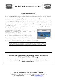
BiggIR Vertical Instruction Manual<br />
SteppIR Antennas<br />
23831 S.E. Tiger MT. RD. - Issaquah, WA 98027<br />
Tel: 425-391-1999 Fax: 425-391-8377 Toll Free: 866.783.7747<br />
Web: www.steppir.com 6/25/04
Topic<br />
Page<br />
BiggIR vertical components 4<br />
Installing the BiggIR 4 - 6<br />
Radial systems for elevated and ground mounted vertical antennas 7 - 11<br />
Using a vertical in or on salt water 11<br />
Connecting the controller to the antenna 12<br />
Using the BiggIR controller 12 - 20<br />
Amateur, General Frequency and Setup mode descriptions 13<br />
Resetting the factory default antennas 14<br />
Transceiver interface 14 - 15<br />
Create or modify an antenna 16<br />
Calibrating the antenna 17<br />
Retracting the element 17 - 18<br />
Operating in 3/4 wavelength mode 18<br />
Using the BiggIR controller with a logging program 19 - 20<br />
Vertical specifications 21<br />
Changing bands while using over 200 watts output power 21<br />
BiggIR product warranty information 22<br />
Safe handling of copper beryllium 22<br />
Small IR installation Addendum 23
SteppIR Antennas 4<br />
Installing the BiggIR Vertical<br />
G<br />
A: Extension EST<br />
B: 25’ Telescoping Fiberglass Pole<br />
C: Antenna Housing with EST<br />
D: 24” x 1.5” OD Aluminum Mounting Tube<br />
E: Diverter Extension<br />
F: Rain / Vent Cap<br />
G: Guy Ring<br />
Lay the antenna housing and element support tube (EST) flat on it’s side (figure 1). There<br />
will be a 3/4” diameter piece of plastic pipe protruding out the end of the EST with a coupler<br />
attached to it (figure 2). Firmly insert the 56” section of 3/4” diameter plastic pipe<br />
(component E, in above picture) as shown in figure 2 and figure 3. The flared end of the<br />
tubing should be pointing away from the antenna housing. You will now want to slide the<br />
second section of the EST tube (Component A in above picture) firmly onto the first section<br />
of the EST tube, as shown in figure 4 and figure 5. Be certain that the coupler on the<br />
extension EST firmly bottoms out. Firmly wrap the joint with electrical tape and vulcanize<br />
with the silicone tape as shown in figure 5a and 5b. It is not necessary to do this if you will<br />
be guying the antenna, because the downward tension created by the guy wires will “lock”<br />
the BiggIR in place. In order to achieve the factory rated wind load of 80 mph, three guy<br />
wires (or ropes) are required (figure 21). Without the guy wires, the antenna is rated at 60<br />
mph maximum wind load.<br />
Figure 1 Figure 2 Figure 3<br />
Figure 4 Figure 5 Figure 5a Figure 5b
SteppIR Antennas 5<br />
The diverter extension will protrude out of the second section of the EST as shown in figure 6. Also<br />
shown in figure 6 is the guy ring. There is a shoulder on the coupler that is attached to the telescoping<br />
pole. Slide the guy ring onto this shoulder (figure 7). Slide the butt end of the telescoping fiberglass<br />
pole over the EST tube until it firmly bottoms out as shown in figure 8. Firmly wrap the joint with<br />
electrical tape and vulcanize with the silicone tape as shown in figure 8b and 8c. It is not necessary to<br />
tape the joints if you will be guying the antenna, because the downward tension created by the guy<br />
wires will “lock” the BiggIR in place.<br />
Figure 6 Figure 7 Figure 8 Figure 8b<br />
Figure 8c<br />
STEP 7: Telescope the fiberglass tube by pulling each joint out firmly, until securely locked in<br />
place and fully extended. When fully extended, the pole must be a minimum of 24’ 8” (296 inches) in<br />
length when measured from the butt end of the pole to the tip. Attach one #16 stainless reinforcing clamp<br />
at the tip of the second section of the telescoping pole, leaving approximately 1/2” from the edge (fig 9).<br />
Figure 10 shows the two clamps together (the sections are telescoped out, so you have to look closely for<br />
the 2nd section reinforcing clamp in the picture). Starting at the 1/2” area to the right of each clamp,<br />
firmly wrap the black 3M tape around each side of the joint, first wrapping in half wraps to the right, and<br />
then overlapping in half wraps to the left. Be sure to pay close attention to the actual joint, an extra wrap<br />
or two at the joint is always recommended (fig 11). Be sure to use plenty of electrical tape on each joint.<br />
Apply the silicone wrap to the left side of the reinforcing clamp, overlapping the clamp in the same manner<br />
as the electrical tape (fig 12). You will want to completely cover the 3M tape so that you will have a<br />
weatherproof seal. The silicone tape will not stick to any surface - it bonds only to itself. The wrap will<br />
immediately start to cure once contact is made, and will be fully cured within 24 hours. You can assist in<br />
the curing by using a hair dryer or heating element if desired. Be sure to firmly press or “rub” the wrap<br />
once it is applied, to ensure that the wrap is properly adhering to itself. On the remaining joints for the<br />
pole, you will not require a reinforcing clamp, but you will still need to wrap the black tape in the same<br />
manner, and cover it with silicone wrap (fig 13 and figure 14). You will use approximately 24”” of silicone<br />
wrap for the largest joint, 22” for the 2nd joint, 17” for the third and 11” of waterproofing for the<br />
smallest joint.<br />
Figure 9 Figure 10<br />
Figure 11 Figure 12<br />
Figure 13<br />
Figure 14
SteppIR Antennas 6<br />
When you are finished taping and wrapping the joints, you will then want to install the aluminum vent<br />
fitting and foam plug on the tip of the telescoping tube. The purpose of the vent cap is to keep the<br />
rain out, yet still allow air flow through the foam plug into the telescoping tube. The foam plug will<br />
already be inside the vent cap. Position the vent cap so it bottoms out on the tip. With the cap positioned<br />
loosely on the tip, wrap 3 or 4 layers of tape flush with the bottom of the vent cap<br />
(approximately 1-5/8” from the tip) as shown in figure 15. This will center the cap when you push it<br />
down onto the tape (figure 16). You will want to push until the vent plug is half way bottomed out, so<br />
that it is centered on the tape, yet will still allow the foam to breathe. Using electrical tape, secure the<br />
cap to the tip of the pole, being careful not to block the vent holes on the bottom of the cap (figure<br />
17). Weatherize the joint by applying silicone wrap over the electrical tap (fig 18)<br />
Figure 15<br />
Figure 16 Figure 17 Figure 18<br />
The SteppIR vertical antenna comes with a 1.5” OD aluminum mounting post, 2 feet in length<br />
(component D in picture on page 2). If using guy wires, the SteppIR vertical can be mounted directly<br />
into the ground without concrete (the guy wires will “lock” the antenna in place) You will want to ensure<br />
that the mounting pole does not shift or settle over time, using concrete to secure it in the ground<br />
is a way to eliminate the potential for this problem. Position the mounting pole so that the bottom of<br />
the element housing is 6 inches above the ground (figure 20). After the mounting post is in place and<br />
level, you are ready to erect your SteppIR Vertical! In order to achieve the factory rated wind load of<br />
80 mph, three guy wires (or ropes) are required (figure 21). Without the guy wires, the antenna is<br />
rated at 60 mph. Connect your guy wires to the guy ring before erecting the vertical, and then slide<br />
the small end of the included flexible connector to the mounting post. This coupler is used to keep the<br />
antenna from potentially “twisting” in high winds. Pick up the antenna at the base (figure 22) and slide<br />
the antenna housing onto the mounting pole (the end that is machined goes into the antenna housing<br />
tube), until it firmly bottoms out (figure 23). Place the larger end of the flexible coupler over the antenna<br />
housing tube (a small amount of bar soap or other lubricant will help the process). Tighten<br />
clamps on the coupler and secure the guy wires. Now you are ready to connect the radials! Figure 24<br />
shows the lug on the antenna housing used for attaching your radial system We recommend using a<br />
lug connector at the end of your radials, and then tightening the lug onto the connector post shown in<br />
figure 24. If you purchased the optional radial kits, you will notice there are 4 wires per set, all soldered<br />
and crimped to a lug connector.<br />
Figure. 20 Figure 21<br />
Figure 22<br />
Figure 23 Figure 24
SteppIR Antennas 7<br />
All vertical monopoles need some form of counterpoise in which antenna image currents flow to work efficiently.<br />
This counterpoise usually consists of a system of radial wires placed either on the ground or elevated<br />
above ground.<br />
This is not an in depth publication but simply a general guide on installing and using the SteppIR verticals.<br />
There is much more information available in various publications if you need it. The ARRL Antenna Handbook<br />
is a good source for additional information.<br />
By following a few simple guidelines, you can obtain excellent performance from vertical antennas mounted<br />
on the ground or elevated above the ground. There are a number of verticals available that say “no radials<br />
required”, but they do have “radials”, in the form of a shortened, tuned counterpoise system. As you might<br />
expect, you pay a price for such a small counterpoise system—less efficiency.<br />
As you will see in the following pages, you can get fairly high efficiency with a relatively modest radial system<br />
that will far outperform small counterpoise systems. It should be noted that counterpoise systems are<br />
only good for curing near field losses caused by losses from the earth, which is a poor conductor of RF, even<br />
with good soil. There is nothing you can do about far field losses that reduce the signal strength and low angle<br />
radiation, except get to some saltwater. We briefly discuss salt water locations later on in this article.<br />
Ground Mount or Elevate<br />
Ground Mounting:<br />
PROS<br />
• The radials can be any length and they work<br />
on all frequencies<br />
• Easy to mount<br />
• Easy access<br />
• Lower visual profile<br />
• Eight to twelve 0.1 wavelength radials gives<br />
60% - 65% efficiency (one set of 8 - 12 radials<br />
cut to 0.1 wavelength at lowest frequency)<br />
CONS<br />
• Takes 120 radials to equal an elevated vertical<br />
with 2 resonant radials (90% efficient)<br />
• Surrounding objects can reduce signal<br />
strength
SteppIR Antennas 8<br />
Elevated Mounting:<br />
PROS<br />
• + 90% efficient with two .25 wavelengthradials<br />
• Antenna is generally more “in the clear”,<br />
so surrounding objects don’t cause as<br />
much attenuation<br />
• A peaked metal roof will make a very good<br />
all-frequency radial system<br />
CONS<br />
• Requires two .25 wavelength radials for<br />
each band of operation (radials interact, so<br />
spacing will affect length)<br />
• Mounting is generally more involved<br />
• Visually higher profile<br />
• Must be mounted high enough that people<br />
won’t walk into it<br />
• Needs to be about .2 wavelengths high to<br />
get an ideal 50 ohm match<br />
• Radials need at least a 20° slope to get a<br />
good match<br />
• Involves adjusting and fine tuning the radial<br />
lengths in some cases<br />
Ground Mounting:<br />
If you chose to ground mount the vertical, pick a spot that will allow you the best chance of spreading<br />
your radials evenly around the antenna, and away from trees and other objects if possible. Mount the antenna<br />
within one foot of ground if possible, the closer to ground the better. Next, you will need to determine<br />
how much effort and wire you are willing to invest in this installation. The tradeoffs are as follows:<br />
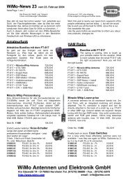
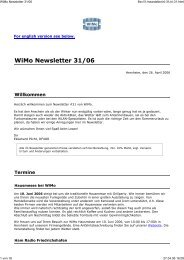
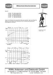
1. More radials equals higher efficiency (see figure 1)<br />
2. More short radials are generally better than a few long ones<br />
3. If only a few radials are going to be used, they need not be very long<br />
4. If you have very good earth (very few of us actually do), you can obtain good performance with very<br />
few radials.<br />
100<br />
80<br />
% Efficiency<br />
60<br />
40<br />
20<br />
Figure 1<br />
0<br />
0 15 30 45 60 75 90 105 120<br />
Number of radials<br />
N b f R di l
SteppIR Antennas 9<br />
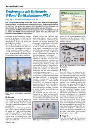
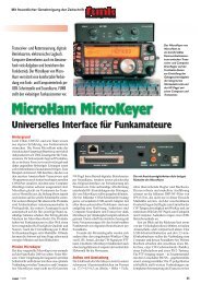
Four radials are what we consider to be the absolute minimum in average soil. How much you<br />
have to gain with good a radial system depends on how good your earth is. Most of us have<br />
poor earth conditions, so the radial system is important. The worse the earth is, the more can<br />
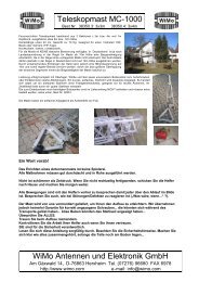
be gained with radials. Figure 2 shows a graph produced by Brian Edward (N2MF) that illustrates<br />
the relative signal gain you get with the radials and varying length over poor earth. With<br />
better earth, the gain difference between 4 radials and 120 radials will be about 2.5 dB, as opposed<br />
to 4 dB with poor earth.<br />
3.6<br />
3<br />
N=120<br />
N=96<br />
120 Radials<br />
96 Radials<br />
2.4<br />
N=48<br />
48 Radials<br />
Relative Gain<br />
1.8<br />
1.2<br />
0.6<br />
N=24<br />
24 Radials<br />
0<br />
N=12<br />
12 Radials<br />
Figure 2<br />
-0.6<br />
-1.2<br />
0 0.06 0.12 0.18 0.24 0.3 0.36 0.42 0.48 0.54 0.6<br />
Radil Length in Wave length<br />
N=4<br />
Radial length in wavelength<br />
4 Radials<br />
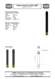
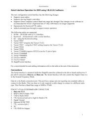
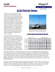
If you are restricted to .1 wavelength radials there is not much advantage to using more than<br />
about 24 radials. You can see from figure 3 that if more radials are used there is a huge advantage<br />
to making them longer.<br />
If you cannot lay the radials out in a symmetrical radial pattern, don’t worry too much - it<br />
will distort your omni-directional pattern a bit but won’t reduce your efficiency very much.<br />
Lay the radials out in the best manner possible given your situation. There are various ways<br />
to accomplish laying a radial system, including turning corners, etc. Good results are limited<br />
only to your creative energy and determination! Be aware that very high voltages can exist<br />
at the ends of radials, so be certain that no one can come into contact with them. It is a good<br />
idea to use insulated wire to protect from corrosion, and don’t bury the radials any deeper<br />
than necessary, one to three inches is sufficient.<br />
0.48<br />
Figure 3<br />
Sufficient Radial Length (wavelength)<br />
0.4<br />
0.32<br />
0.24<br />
0.16<br />
0.08<br />
0<br />
0 15 30 45 60 75 90 105 120<br />
Number of Radials (N)<br />
Number of radials
SteppIR Antennas 10<br />
Elevated Mounting:<br />
You can elevate a vertical just a few feet from the ground (4 feet for 20m, 8 feet for 40m) and get<br />
fairly good performance with just 2 radials (elevated as well) per band of operation. The problem<br />
is you won’t have a very good match to 50 ohms, and the close proximity of the earth will degrade<br />
the signal - especially if it is poor earth. For ideal matching, we recommend .2 wavelength (about<br />
15 feet on 20m and 30 feet on 40m) at the lowest planned frequency of operation As the height decreases<br />
below .2 wavelength, the ground losses start to increase, unless you have very good ground.<br />
When a vertical is raised off the ground the impedance drops fairly rapidly from 36 ohms (Over<br />
perfect ground or with many radials it will be close to 36 ohms, over real ground it is generally 40–<br />
60 ohms) to about 22 ohms when .3 wavelength is reached. This would make a pretty poor match<br />
to 50 ohms, so a couple of tricks are in order. Once you elevate a vertical, two radials are all you<br />
really need. It is important that you try to keep a 180° angle between the two (opposed, directly in<br />
line) for the best pattern. Spread the radials out as far as possible to reduce interaction, if they are<br />
less than a foot apart it can be difficult to get a good match on all bands. To facilitate a match to 50<br />
ohms you can angle the radials downward, this raises the impedance of the antenna as you increase<br />
the angle downward. Figure 4 shows the approximate relationship of radial angle to impedance:<br />
Figure 4<br />
Radial Droop Angle = Antenna Impedance<br />
0° = 22 Ohms<br />
10° = 28 ohms<br />
20° = 35 ohms<br />
30° = 47 ohms<br />
40° = 53 ohms<br />
50° = 55 ohms<br />
Note: above 50° results in diminishing returns
SteppIR Antennas 11<br />
Elevated Mounting (continued)<br />
Can’t get enough droop angle to achieve a good match Simply adjust the antenna element<br />
slightly longer than the factory 1/4 wavelength (up to 20% longer) settings and the impedance<br />
will rise. This will cause the radials to be too long, so they may need to be pruned a bit. Be<br />
aware that increasing the antenna 2% to 3% longer may require radials to be 5% to 7% shorter.<br />
Once you have a good match, replace the factory default values by saving the new antenna (to<br />
do this you will use the “create, modify” feature in the setup mode).<br />
When the vertical is elevated you can get away with just one resonant radial, however, the pattern<br />
won’t be omni-directional. You will have -12 dB to 15 dB null in one direction<br />
Using a Vertical in on or Near Salt Water:<br />
If you are lucky enough to have a dock over salt water, a vertical can offer unparalleled performance<br />
for low angle DX. Simply mount the vertical to the dock and attach two radials for<br />
band of operation. They can be stapled right to the dock if it is non-metallic. Mounting the<br />
vertical in ground flooded by salt water a couple of times per day can be equally effective.<br />
Proximity to the ocean improves the far field loss of a vertical and allows very low angle radiation<br />
- get as close to the water as possible to enhance performance.<br />
Due to the fact that RF does not penetrate more than 2 inches into the water, direct coupling<br />
(a wire in the water) is difficult. Objects like metal floats or boats, providing they are large<br />
enough, can make good grounds in salt water. If you are using a metal boat or large metal<br />
object, corrosion is no longer a problem because the large surface capacitively couples to the<br />
water. When using a small metal float (3 ft x 3 ft is just enough to “connect” to salt water),<br />
you want to be certain that the metal does not corrode over time. For long term immersion,<br />
Monel is a good (but fairly expensive ) choice.
SteppIR Antennas 12<br />
Connecting the controller to the antenna<br />
On the back of your controller, there are two power connections: primary, and AUX. You can use either<br />
one of these to connect the included 24 volt power supply cord. The AUX is intended for use<br />
with 4 antenna elements or more.<br />
Once you have connected the power cord to the controller and plugged the other end of the cord into<br />
the power outlet (the universal power supply can accept 100 - 240 volts AC), you will want to turn<br />
the controller on by pushing the on/off button located on the front of the controller. It is advisable<br />
that you do not hook the antenna control cable to the controller when turning the unit on for the first<br />
time, so that you can be certain that the controller display reads “elements retracted”. If it the LCD<br />
display does not say this, you will want to refer to “retracting the elements” on page 17. When the<br />
display reads “Elements Retracted”, you can then hook the control cable up to the back of the controller.<br />
This is accomplished by mating the 25 pin male connector on the cable to the 25 pin female connector<br />
in the middle of the back panel of the controller.<br />
Also on the back of the controller, are two ports - “Data In” and “Data Out”. If you have purchased<br />
the transceiver interface option, there will be two 9 pin d-sub male connectors in the ports. If you<br />
have not purchased the interface, there will be plastic covers over the ports. For more information on<br />
the transceiver interface refer to page 14<br />
Using the BiggIR controller
SteppIR Antennas 13<br />
Using the BiggIR Controller - Modes of Operation<br />
There are three modes of operation with the SteppIR controller: Amateur, General Frequency and Setup.<br />
To access any of these modes, press the “mode” button, located at the bottom right corner of your controller<br />
front panel. The mode button is a 3 position toggle, each time you press the button, the controller<br />
will change to the next mode, and the respective LED will light up adjacent to the mode description. It<br />
is important that you click on the “select” button within 2-1/2 seconds after arriving at the desired mode.<br />
If you do not, the controller will default back to the last mode you were at. The select button is located<br />
just to the right of the mode button.<br />
Amateur Mode:<br />
When in the amateur mode, to tune through the bands you simply press the desired band button, and the<br />
controller will simultaneously adjust the length of the element to that segment. To tune the antenna<br />
from this point, you simply press either the up or down button, and the antenna will tune 50 KHz per<br />
click. When in the amateur or general frequency mode, whenever the antenna is adjusting an asterisk<br />
will flash. When the antenna has finished adjusting, the asterisk will disappear. It is important that you<br />
do not transmit while the antenna is tuning if you are operating with more than 200 watts.<br />
General Frequency Mode:<br />
There are three purposes for the general frequency mode:<br />
For manual operation, it allows you to scroll through the bands quicker - each time you manually press<br />
the up / down arrows the controller will tune 100 KHz, as opposed to 50 KHz per click in amateur<br />
mode. When you continuously press the up / down button without releasing it, after a few seconds the<br />
tuning adjustment will ramp up to a faster speed, tuning at the rate of 1 MHz at a time.<br />
If you have purchased the transceiver interface option for your BiggIR, you will need to be in the general<br />
frequency mode in order for it to function. Refer to the transceiver interface section on page 14 for<br />
more information.<br />
In general frequency mode, you can save up to 6 frequencies to memory. Simply adjust to the desired<br />
frequency, then hold one of the band buttons down until it starts blinking, and then release the button.<br />
The new frequency has now been saved into memory.<br />
Setup Mode:<br />
The setup mode is the mode you use when you want to set up or change certain features of the controller.<br />
When you first enter setup, the screen will say “mode key to exit , up / dn to scroll”. “Mode key to<br />
exit” means that if you want to exit back to either the amateur or general frequency mode from this<br />
point, you would simply press the mode button once and you would exit. “Up / dn to scroll” means that<br />
if you press either the up button or the down button, the controller will scroll through the setup menu.<br />
Once you get to the desired menu, you press the select button to “enter” that menu item. Each function<br />
in the setup mode is explained in detail on the following pages.
SteppIR Antennas 14<br />
Factory Default<br />
When your controller is sent to you, it has 8 factory default antenna lengths in it for the forward direction antenna.<br />
These are the antenna lengths that we have computer modeled and field tested - and stored into the<br />
memory of your controller. At any point, you can change the lengths of these antennas, and save them to<br />
memory (for more information on creating or modifying antennas, refer to the “create modify” menu on page<br />
16. When you save the new antennas, you are replacing the old factory defaults with your new antenna<br />
lengths. At some point, you may decide that you want those factory antenna lengths back. This is what the<br />
“factory default” section is for. You can restore the factory default for a specific antenna segment, or you can<br />
completely restore all of the factory defaults at once.<br />
If you want to restore the factory default on a single antenna segment, first you will want to go to that segment<br />
in either the amateur mode or the general frequency mode. For example: Let’s say you had previously replaced<br />
the antenna segment 14.200 with a new antenna length. Now you have decided that you want to restore<br />
the factory default antenna that was originally in that segment. To do this, first you would go to the 14.200 antenna<br />
segment while the controller was in the amateur mode. You would leave the antenna at this position,<br />
and then proceed to the “factory default” menu in the setup mode.<br />
When you first enter setup mode, you will see “mode key to exit, up / dn to scroll” on the LCD screen. Press<br />
the up button once, and it will take you to “factory default”. Press the select button to enter into this menu.<br />
The second line of the LCD screen will say “Current YES NO”, and the NO will be blinking. The controller<br />
is asking you if you want to revert back to the factory default for the current antenna segment you are on (in<br />
our example, 14.200). Entering YES gives you back the original antenna lengths that came with the controller<br />
for that segment. To enter YES, you simply press the up or down button, and YES will start flashing. Press<br />
the select button, the factory default has been restored for that single antenna segment. If you select NO, the<br />
screen will then say “All Ant YES NO”, with the NO blinking. The controller is asking you if you want to<br />
replace all of the antenna segments that are now saved in the controller memory with the original factory default<br />
lengths. To do so, press either the up or down button once, and the YES button will now be flashing.<br />
Press the select button, and now every one of the factory default antennas has been restored. If you decide not<br />
to restore the defaults, you would press NO, and you would be taken back to the setup “factory default” main<br />
menu. From there, you can either use the up / dn arrows to further scroll through the setup menu, or you could<br />
press the mode button to go back to amateur or general frequency mode.<br />
Transceiver Interface<br />
This menu item is used if you have purchased the optional transceiver interface. To use the transceiver interface,<br />
you need to have a rig that has computer interfacing capability. Rigs with these options were primarily<br />
manufactured from 1990 on. When enabled, the transceiver interface on the SteppIR controller will “listen” to<br />
your rig, and will automatically re-adjust every 50 KHz as you tune through the bands.<br />
The following are radios that we know will work with our transceiver interface module. New radios are added<br />
periodically. Note: If you do not see your rig here, that does not necessarily mean the interface will not work.<br />
If your rig has an interface, call the factory to be certain whether the interface will work with our controller.
SteppIR Antennas 15<br />
Transceiver Interface (continued)<br />
Icom: All radios that have a CI-V port; 706, 746, 746 PRO, 756, 756 PRO, 756 PROII, 765, 775, 781<br />
Kenwood: TS50, TS570, TS570G, TS850, TS870, TS950SD, TS950SDX, TS2000<br />
Yaesu: FT-847, FT1000D, FT1000MP, FT1000MP Mark V<br />
Ten-Tec: Omni VI, Omni VI Plus; These radios emulate ICOM protocal<br />
SGC: Some of their rigs emulate Kenwood TS-570; these will work with the SteppIR transceiver interface<br />
If you have the transceiver interface option, your controller will come with an interface cable, which has a 9 pin<br />
d-sub connector on one end that hooks up to the “Data In” port on the back of the controller. The other end will<br />
go to your rigs interface. The transceiver interface option will work with any of the above rigs listed, but the<br />
cable connections vary in type depending on the radio manufacturer. We also can supply a wye cable that allows<br />
the user to run a logging program concurrently with the SteppIR controller.<br />
Icom uses a mini phono plug connection for their CI-V ports, Yaesu has a 9 pin D sub connection. The newer<br />
Kenwood radios use 9 pin D sub connectors, the older Kenwood radios use 6 pin DIN connectors. If you want<br />
to use the SteppIR interface with different rigs, you may require additional interface cables, which are available<br />
for purchase from SteppIR Antennas.<br />
When you first enter setup mode, you will see “mode key to exit, up / dn to scroll” on the LCD screen. Press<br />
the up button twice, and it will take you to “Transceiver Setup, up / dn to scroll”. To enter, press the select button.<br />
A new screen will appear saying “Baud Mode Done” with DONE flashing.<br />
The baud rate is the speed in which information is exchanged between the SteppIR controller and your radio.<br />
This setting must be the same as the setting in your radio, or the interface will not function. To set the baud<br />
rate, press the up or down arrow until BAUD is flashing, and then press the select button. You can then use the<br />
up or down arrows to adjust to the proper setting. If you are not sure what this setting is, refer to the users manual<br />
for your radio. When the proper baud rate is showing, press the select button. BAUD will now be flashing<br />
again.<br />
Now you will want to set up the mode, which is the radio type you will be using. The radios to choose from<br />
are: Icom, Kenwood, Yaesu FT847, 1000D, 1000MP and OFF. Press the up or down arrow until MODE is<br />
flashing and then press the select button. Now you can use the up or down arrow to scroll through until the<br />
proper mode selection is visible. Press the select button, and MODE will be flashing again. To save these settings,<br />
use the up or down arrow until DONE is flashing again, and press the select button. The controller will<br />
ask you if you want to save these settings, and NO will be flashing. If you do not want to save your changes,<br />
press the select button while NO is flashing. If you do want to save them, press select while YES is flashing.<br />
YOU MUST NOW TURN THE CONTROLLER OFF AND THEN TURN THE CONTROLLER BACK ON<br />
AGAIN BEFORE THE SETUP WILL TAKE PLACE. Once this is done, press the mode button until the<br />
“general frequency” LED is lit, and then press select within 2-1/2 seconds. When you tune your rig, the SteppIR<br />
controller should now automatically re-adjust every 50 KHz.
SteppIR Antennas 16<br />
Create, Modify<br />
The create, modify menu allows you to change the length of the BiggIR for any antenna segment. In the<br />
case of the vertical antenna, the “driven” element is the only one you will need to be concerned with. You<br />
can use this feature to try out your own antenna designs, or to “tune out” potential objects that are causing<br />
interaction or SWR problems with your antenna. This feature is especially good for those of you who experiment<br />
with modeling programs such as EZ-NEC or YO PRO. Computer modeling has dramatically<br />
simplified antenna design. With this technology (many modeling programs are available on the internet)<br />
the average ham can create his/her own antennas and have a very accurate idea as to what kind of performance<br />
to expect before the antenna is built. While modeling has been a great help, in the past, when<br />
the modeling was done you still would have to go outside and make the necessary modifications in length<br />
for every single antenna design, which could be quite cumbersome and time consuming. With the SteppIR<br />
adjustable antenna, we have advanced antenna design technology one step further - now you can<br />
model and build as many different antennas you want, without ever leaving your ham shack! Remember,<br />
however, that modeling programs output the electrical length of the element - not the physical length. Our<br />
controller indicates the physical length of the element. The electrical length is from 2% to 3.5% longer<br />
due to conductor diameter, mounting hardware and dielectric loading from the telescoping fiberglass support<br />
poles. We have this data accounted for, and programmed into the factory default antenna length. If<br />
you are doing some serious modeling, call or email us at the factory and we can give you more data on<br />
electrical lengths.<br />
When you are finished changing the respective lengths, you can save the new antenna to memory, overriding<br />
the factory default antenna segments. If at any point you want to restore the factory default antennas,<br />
you can do so by going to the “Factory Default” menu in setup, which allows you to easily restore either a<br />
single antenna segment, or every one of them if necessary.<br />
When changing an antenna length, the first thing you will need to do is go to the antenna segment you<br />
want to change, whether you are in amateur mode or general frequency mode. When you are at the antenna<br />
segment you wish to change, you can press 3 buttons simultaneously (up arrow, down arrow and select<br />
button) and you will immediately enter the create modify mode. All you have to do from here is use<br />
the up / down arrows to reach the desired length, and press select. From there, use the up / down buttons<br />
to scroll to DONE, and press select. Select yes or no, and you are done! Or, you can go to the setup<br />
mode, and from there to the create, modify menu. To enter, press the select button. A new screen will appear<br />
saying “DIR DVR REF DONE” with DVR flashing. For the BiggIR, only the DVR (driven element)<br />
is of any consequence, since there is only one element on this antenna. To change the antenna<br />
length for this segment, press the select button. Now the display will say Up Dn to adjust, which means<br />
use the up or down arrows to adjust the length of the driven element to your desired length. Individual<br />
clicks will change the length 0.1” at a time, and if you hold the button down, after a few seconds the controller<br />
will ramp up to a higher speed. Once you have reached the desired length, press the select button.<br />
DVR will be flashing again, with the new length shown on the second line of the LCD screen. If this is<br />
the desired length, press the up / down arrow until DONE is flashing again, and press the select button.<br />
The screen will read “SAVE YES NO, with NO flashing. Use the up / down button to choose the<br />
proper choice and press the select button. If you selected yes, the new lengths will be saved into memory<br />
for the antenna segment you are currently on. If you select no, no changes will be made, your antenna<br />
segment will be just as it was before. Remember, if you ever need to restore the factory defaults, this can<br />
be easily accomplished. Refer to the “factory default” instructions for more information.
SteppIR Antennas 17<br />
Calibrate<br />
Calibrating the antenna ensures that the element lengths are exactly what the controller display says they<br />
are. Usually, the only way the antenna can get out of calibration is if the power is interrupted or the cable<br />
is somehow disconnected while the antenna is changing length. The controller doesn’t “know”<br />
where the antenna is adjusted to unless you start at a known place. The antenna housing sent to you has<br />
the element retracted inside, and the controller is set to “elements retracted”. If you power up the controller<br />
and it says “elements retracted”, and you connect the antenna control cable with the elements<br />
physically retracted, you are “calibrated” and ready to go!<br />
If you need to calibrate, it is a simple, two click operation. When you select calibrate, the antenna will<br />
retract all of the elements, and the stepper motor will continue to over-step for a few moments after the<br />
elements have retracted. In doing this, the controller is making sure that there is not a shadow of a doubt<br />
that each element is fully retracted, and back to the known starting point. When calibrating, you will<br />
hear a buzzing noise for about 30 seconds, this is normal. When calibration is finished, the antenna will<br />
go to the last segment you were on when you started the calibration process. Then entire process takes<br />
less than a minute. Whenever your antenna is not acting as it should, we highly recommend that you use<br />
the calibrate function before exploring other potential problems. Always calibrate when in doubt—it is<br />
easy, and doesn’t hurt a thing!<br />
When you first enter setup mode, you will see “mode key to exit, up / dn to scroll” on the LCD screen.<br />
Press the up button four times, and it will take you to “Calibrate, up / dn to scroll”. To enter, press the<br />
select button. A new screen will appear saying “Calibrate YES NO”, with NO flashing. To calibrate<br />
the antenna, press the up or down button until YES is flashing, and then press the select button. The<br />
screen will now say “Calibrate” with the second line saying “Homing Elements”. You will notice that<br />
the asterisk will be flashing the entire time the antenna is calibrating. When the controller is done calibrating<br />
the antenna, the screen will then show the last antenna segment you were on, with the asterisk<br />
still flashing to show that the controller is now adjusting the antenna to the last segment you were on before<br />
you calibrated. When the asterisk quits flashing and disappears, calibration is complete and you are<br />
ready to go!<br />
Retract Elements<br />
If you ever plan on taking your antenna down, you will first need to retract the elements. In addition, if<br />
you want to protect your antenna during periods of non-use, or during lightning storms or harsh winter<br />
conditions, you can use the retract element feature for this as well. Many of our customers have retracted<br />
their elements during lightning storms, significantly reducing the conductive area of the antenna<br />
platform. In ice storms, SteppIR users have also been able to retract their elements, greatly reducing the<br />
potential for loss in case of a catastrophic failure. When you retract the elements, the copper beryllium<br />
conductive strip is “safe and sound” inside the antenna housing, leaving only the telescoping fiberglass<br />
poles. These poles are easy to replace and reasonable in price ($20 each for SteppIR owners), so even if<br />
you damage the telescoping fiberglass support elements, the most valuable part of the antenna will be<br />
safe!
SteppIR Antennas 18<br />
Retract Elements (continued)<br />
When you first enter setup mode, you will see “mode key to exit, up / dn to scroll” on the LCD<br />
screen. Press the up button five times, and it will take you to “Retract Elements, up / dn to scroll”. To<br />
enter, press the select button. A new screen will appear saying “Home Now YES NO, with NO<br />
flashing. The controller is asking you if you want to send the elements “home”, which means retracting<br />
the elements. To retract the antenna, press the up or down button once, and YES will start flashing.<br />
Press the select button, the display will say “Home Now / Homing Elements”. The asterisk will be<br />
flashing, this means that the antenna is retracting, when the asterisk disappears, the new message will<br />
read “Element Retracted”. Your antenna is now safely inside the antenna housings. When you want to<br />
put the antenna back on the air, simply press the antenna segment you desire, and the controller will<br />
adjust to that segment.<br />
3/4 Wavelength mode<br />
This feature allows you to switch your vertical antenna from the standard 1/4 wavelength to a 3/4<br />
wavelength vertical. A 3/4 wave vertical antenna has a 4 dB advantage over a 1/4 wave vertical, and<br />
some higher angle energy. We have provided this mode to give you the flexibility of trying both ways<br />
when the going gets tough. This feature only works from 21.000 MHz through 54 MHz. When no<br />
LED is lit, you are in normal, or 1/4 wavelength mode. When the LED is lit, you are now in 3/4 wavelength<br />
mode.
SteppIR Antennas 19<br />
Using the SteppIR controller with your logging program<br />
Logging programs fall into two groups; programs with manual rig control (like TRX-Manager), which allow<br />
you to control the radio from the computer, and programs that are focused on logging, with the ability<br />
to set the rig to the correct frequency through a spot (like DX Base). The first type of programs poll the radio<br />
continuously to get the frequency. These programs work with the SteppIR by using a “Y” cable to link<br />
the computers receive data together with the SteppIR’s receive data. This way, when the logging program<br />
request the radio data, the SteppIR controller also receives a response. There will be a slight delay depending<br />
on how fast you have the polling set in the software. The only caveat is that the logging program must<br />
be active on the computer for the SteppIR controller to follow the frequency.<br />
The programs that are designed to strictly do “spots” will only be recognized by the SteppIR controller<br />
when a spot is selected. Some of these logging programs can be linked to TRX-Manager to get the benefits<br />
of both programs. Most of the logging programs, such as Logger, Log Windows and TRX-Manager,<br />
send the spot frequency information to the radio and then ask the radio if it got the frequency information<br />
OK. The SteppIR controller can only listen to the radio data, not the logging program data, therefore those<br />
logging programs that send spot data and do not query the radio (such as Logic 6 and DX-Base)<br />
will not work with the SteppIR controller. However, these programs will work if used in conjunction with<br />
TRX-Manager.<br />
Icom<br />
The Icom is unique in that it has no conflicts when using logging programs of any type with the SteppIR<br />
controller. This is because the Icom uses a shared serial Buss (CI-V) that can have up to 5 devices connected<br />
to it. The SteppIR controller connects to this Buss through a 3.5 mm phono plug. If you are using<br />
the Icom CT-17 to interface to your PC, it already has 5 C-IV connectors that the SteppIR can be plugged<br />
into. Otherwise, you can simply parallel the SteppIR controller and the radio by using a simple “Y” connector<br />
available at Radioshack. The part number for this connector is #274-889.<br />
Radio Shack #274-889 Gold Y Adapter for use with Icom radios<br />
Kenwood and Yaesu<br />
If you are using a Kenwood or Yaesu radio, you will not be able to use the Radioshack connector<br />
mentioned above. You must use a “Y” cable, which is available from SteppIR Antennas, or you can build<br />
it yourself by referring to the drawing on page 20.
SteppIR Antennas 20
SteppIR Antennas 21<br />
6WHSS,5<br />
Yagi z Dipole<br />
TM<br />
(<strong>Patent</strong> <strong>Pending</strong>)<br />
Specifications BiggIR SmallIR<br />
:HLJKW<br />
0D[ ZLQG VXUI DUHD<br />
OE<br />
NJ<br />
IWð<br />
Pð<br />
OE<br />
NJ<br />
IWð<br />
Pð<br />
*X\HG ZLQG VXUYLYDO<br />
Z JX\V# <br />
03+ 03+<br />
8Q*X\HG ZLQG VXUYLYDO PSK 03+<br />
(OHPHQW OHQJWK<br />
IW<br />
P<br />
IW<br />
P<br />
0D[LPXP SRZHU :<br />
3(3<br />
:<br />
3(3<br />
)UHTXHQF\ FRYHUDJH 0+] <br />
&DEOH 5HTXLUHPHQWV FRQG FRQG<br />
7XQLQJ 5DWH<br />
0+] <br />
6HFRQG<br />
0+] <br />
6HFRQG<br />
5DGLDO 6\VWHP<br />
5HTXLUHG"<br />
SteppIR Antennas 22<br />
)OXLGPRWLRQ,QFRUSRUDWHG<br />
6WHSS,5 TM<br />
<br />
/LPLWHG:DUUDQW\<br />
<br />
7KHVHSURGXFWVKDYHDOLPLWHGZDUUDQW\DJDLQVW<br />
PDQXIDFWXUHUVGHIHFWVLQPDWHULDOVRUFRQVWUXF<br />
WLRQIRUWZR\HDUVIURPGDWHRIVDOH'RQRW<br />
PRGLI\WKLVSURGXFWRUFKDQJHSK\VLFDOFRQ<br />
VWUXFWLRQZLWKRXWWKHZULWWHQSHUPLVVLRQRI)OX<br />
LGPRWLRQ,QFRUSRUDWHG7KLVOLPLWHGZDUUDQW\LV<br />
DXWRPDWLFDOO\YRLGLILPSURSHUVHOHFWLRQLQVWDO<br />
ODWLRQXQDXWKRUL]HGPRGLILFDWLRQVRUSK\VLFDO<br />
DEXVHEH\RQGWKHPDQXIDFWXUHUVFRQWUROKDVRF<br />
FXUUHG0DQXIDFWXUHUVUHVSRQVLELOLW\LVVWULFWO\<br />
OLPLWHGWRUHSDLURUUHSODFHPHQWRIGHIHFWLYH<br />
FRPSRQHQWV7KHPDQXIDFWXUHUDVVXPHVQRIXU<br />
WKHUOLDELOLW\<br />
Safe Handling of Copper Beryllium<br />
Handling copper beryllium in solid form poses no special<br />
health risk. When sanding or grinding, avoid inhalation<br />
or contact with dust or vapors. Wash hands<br />
with soap and warm water after handling. For more<br />
information about copper beryllium, please contact:<br />
Brush Wellman Engineered Materials<br />
800-321-2076
6WHSS,5 TM<br />
Yagi z Dipole zVertical<br />
(<strong>Patent</strong> <strong>Pending</strong>)<br />
SmallIR Addendum<br />
The SmallIR is much easier to assemble than the BiggIR so we have not made a<br />
separate SmallIR manual. The information in the BiggIR manual applies to the<br />
SmallIR in every area except the actual assembly. On the SmallIR you do not have<br />
the following:<br />
1. Extension EST<br />
2. 25’ Telescoping Fiberglass Pole (it is 18’)<br />
3. Diverter extension<br />
4. Guy ring<br />
With the SmallIR you simply prepare the telescoping fiberglass pole and place the<br />
rain cap on the end of the tube, just as the manual shows. The fiberglass pole is<br />
then inserted into the EST tube on the antenna housing and secured with the provided<br />
PVC quick disconnect clamp with the two stainless steel clamps. Tighten the<br />
clamps securely to prevent water from getting into the antenna housing. Be careful,<br />
you can strip the clamps if you get overzealous. The rest of the manual applies<br />
to both verticals, with the exception of the 3/4 wave option—the SmallIR only<br />
works in the 3/4 wave mode on 6 meters.
6WHSS,5 TM<br />
Yagi z Dipole zVertical<br />
(<strong>Patent</strong> <strong>Pending</strong>)<br />
SteppIR Antennas<br />
Web: www.steppir.com