intermodal transportation of iso containers and its implementation to ...
intermodal transportation of iso containers and its implementation to ...
intermodal transportation of iso containers and its implementation to ...

You also want an ePaper? Increase the reach of your titles
YUMPU automatically turns print PDFs into web optimized ePapers that Google loves.
Međunarodna naučna konferencija<br />
MENADŽMENT 2010<br />
Kruševac, Srbija, 17-18. mart 2010<br />
Krusevac, Serbia, 17-18 March, 2010<br />
International Scientific Conference<br />
MANAGEMENT 2010<br />
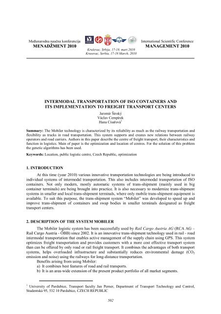
INTERMODAL TRANSPORTATION OF ISO CONTAINERS AND<br />
ITS IMPLEMENTATION TO FREIGHT TRANSPORT CENTERS<br />
Jaromír Široký<br />
Václav Cempírek<br />
Hana Císařová 1<br />
Summary: The Mobiler technology is characterized by <strong>its</strong> reliability as much as the railway <strong>transportation</strong> <strong>and</strong><br />
flexibility as trucks in road <strong>transportation</strong>. This system supports <strong>and</strong> creates new relations between railway<br />
opera<strong>to</strong>rs <strong>and</strong> road carriers. Authors in this paper describe the centre <strong>of</strong> freight transport, their characteristics <strong>and</strong><br />
function in logistics. Main <strong>of</strong> paper is the optimization <strong>and</strong> location <strong>of</strong> centres. For the solution <strong>of</strong> this problem<br />
the genetic algorithms has been used.<br />
Keywords: Location, public logistic centre, Czech Republic, optimization<br />
1. INTRODUCTION<br />
At this time (year 2010) various innovative <strong>transportation</strong> technologies are being introduced <strong>to</strong><br />
individual systems <strong>of</strong> <strong>intermodal</strong> <strong>transportation</strong>. This also includes <strong>intermodal</strong> <strong>transportation</strong> <strong>of</strong> ISO<br />
<strong>containers</strong>. Not only modern, mostly au<strong>to</strong>matic systems <strong>of</strong> trans-shipment (mainly used in big<br />
container terminals) are being brought in<strong>to</strong> practice. It is also necessary <strong>to</strong> modernize trans-shipment<br />
systems in smaller <strong>and</strong> local trans-shipment terminals, where only mobile trans-shipment equipment is<br />
available. To suit this purpose, the trans-shipment system “Mobiler” was developed <strong>to</strong> speed up <strong>and</strong><br />
improve trans-shipment <strong>of</strong> <strong>containers</strong> <strong>and</strong> swap bodies in smaller terminals designated as freight<br />
transport centers.<br />
2. DESCRIPTION OF THE SYSTEM MOBILER<br />
The Mobiler logistic system has been successfully used by Rail Cargo Austria AG (RCA AG –<br />
Rail Cargo Austria - ÖBB) since 2002. It is an innovative trans-shipment technology used in rail - road<br />
<strong>intermodal</strong> <strong>transportation</strong> that enables active management <strong>of</strong> the supply chain using GPS. This system<br />
optimizes freight <strong>transportation</strong> <strong>and</strong> provides cus<strong>to</strong>mers with a more cost effective transport system<br />
than can be <strong>of</strong>fered by only road or rail freight transport. It combines the advantages <strong>of</strong> both transport<br />
systems, helps overloaded infrastructure <strong>and</strong> substantially reduces environmental damage (CO 2<br />
emission <strong>and</strong> noise) using the railways for long-distance <strong>transportation</strong>.<br />
Benef<strong>its</strong> arising from using Mobiler:<br />
a) It combines best features <strong>of</strong> road <strong>and</strong> rail transports.<br />
b) It is an area-wide extension <strong>of</strong> the present product portfolio <strong>of</strong> all market segments.<br />
1 University <strong>of</strong> Pardubice, Transport faculty Jan Perner, Department <strong>of</strong> Transport Technology <strong>and</strong> Control,<br />
Studentská 95, 532 10 Pardubice, CZECH REPUBLIC<br />
502
c) It represents the “last mile missing link”, enables deliveries “Just in Time” <strong>and</strong> “ Just in<br />
Sequence”.<br />
d) Greater cost savings (trans-shipment charges) using swap-bodies adjusted for <strong>intermodal</strong><br />
transport un<strong>its</strong> in compar<strong>iso</strong>n with classic <strong>intermodal</strong> <strong>transportation</strong>s.<br />
e) It is an effective method <strong>to</strong> cope with changes in road traffic streams.<br />
f) It is a suitable alternative method <strong>to</strong> utilize railway infrastructure <strong>of</strong> secondary railways.<br />
Opportunities for using trans-shipment system Mobiler are as follows:<br />
a) For cus<strong>to</strong>mers who do not have their own railway sidings at the nearest railway station with<br />
general loading <strong>and</strong> unloading tracks.<br />
b) For cus<strong>to</strong>mers with their own railways the technology extends their existing <strong>transportation</strong><br />
possibilities.<br />
c) A solution where there is no st<strong>and</strong>ard <strong>intermodal</strong> transport terminal nearby.<br />
d) In industrial zones without railways.<br />
e) In all railway stations with general loading <strong>and</strong> unloading tracks, <strong>of</strong>fering safe h<strong>and</strong>ling <strong>of</strong><br />
almost all kinds <strong>of</strong> goods.<br />
Ideal use <strong>of</strong> the system Mobiler can be defined by following requirements:<br />
a) All kinds <strong>of</strong> goods which can be loaded:<br />
- St<strong>and</strong>ardized or adjusted transport un<strong>its</strong>, especially bulk freight, e.g.: building<br />
material, slag, waste, cinder, chips, pallets;<br />
- Tank <strong>containers</strong>, especially aviation fuel, beverages, cooking oils;<br />
- Pallets in food <strong>and</strong> beverage logistics <strong>and</strong> building industry (e.g. bagged cement, lime,<br />
plaster, etc).<br />
b) Potential cus<strong>to</strong>mers entering the transport market with new requirements for transport or for<br />
current cus<strong>to</strong>mers who are interested in improved economical results;<br />
c) Up <strong>to</strong> 10 000 <strong>to</strong>ns <strong>of</strong> regularly transported goods per year;<br />
d) Transport distance at least 100 km on rail <strong>and</strong> for a maximum <strong>of</strong> 3 different dispatches or<br />
initial points;<br />
e) Transport distance max. 25 – 35 km <strong>to</strong> the railway trans-shipment point;<br />
f) Negotiating long-term freight contracts (more than 5 years).<br />
Transshipment technology „Mobiler“ can be assembled on<strong>to</strong> mass-produced N3 trucks, or O4<br />
trailers (see Fig. 1).<br />
Figure 1 - 5-axle N3 truck <strong>and</strong> 3-axle O4trailer 3 (Source: Authors)<br />
The weight <strong>of</strong> the technology <strong>its</strong>elf produced by Palfinger (see Fig. 2) is 1,5 t <strong>to</strong> 2,5 t<br />
(depending on <strong>its</strong> load-carrying capacity), it means that the technology does not reduce loading<br />
parameters <strong>of</strong> trucks. The system can transship swap-bodies 7 150 <strong>to</strong> 7 850 mm long <strong>and</strong> ISO<br />
<strong>containers</strong> - 20´, 30´ <strong>and</strong> 40´ long. Swap-bodies must be equipped with two lateral channels in the<br />
bot<strong>to</strong>m frame (see Fig. 3) <strong>to</strong> which the shift traverses slide in.<br />
Tank swap-bodies or <strong>containers</strong> can be equipped with permanent (Fig. 3) or adaptive fastening<br />
attachments for h<strong>and</strong>ling shift traverses. The trucks used for their <strong>transportation</strong> are 3, 4 or 5-axle<br />
trucks or 3-axle trailers with hydraulic dumpers.<br />
503
Figure 2 - Detail <strong>of</strong> the Mobiler trans-shipment system (Source: Authors)<br />
Figure 3 - Detail <strong>of</strong> the lateral channel <strong>of</strong> the swap-body (Source: Authors)<br />
Figure 4 - Shift traverse on the welded plate <strong>of</strong> the railway wagon (Source: Authors)<br />
St<strong>and</strong>ard railway wagons for <strong>intermodal</strong> <strong>transportation</strong> (i.e. wagons for the <strong>transportation</strong> <strong>of</strong><br />
<strong>containers</strong> <strong>and</strong> swap-bodies, especially those labeled S – Sggmrss, Sgnss, etc.) must have welded<br />
plates on the loading area enabling step-by-step movement <strong>of</strong> shift traverses. Mobiler technology can<br />
trans-ship un<strong>its</strong> <strong>of</strong> <strong>to</strong>tal weight 18, 25 a 32 t. It is therefore flexible at any place <strong>and</strong> anytime. The<br />
trans-shipment <strong>of</strong> un<strong>its</strong> takes several minutes (it takes approx. 10 minutes <strong>to</strong> pick up the empty unit<br />
<strong>and</strong> swap over the loading unit). The unquestionable advantage <strong>of</strong> this system is that the transshipment<br />
<strong>and</strong> h<strong>and</strong>ling can be carried out under the traction mains power <strong>and</strong> that it is safe for<br />
h<strong>and</strong>ling with hazardous goods. Older trucks use luminescent strips for exact positioning <strong>to</strong> the<br />
railway wagon (see Fig. 5), more modern lorries solve this problem by au<strong>to</strong>matic sensors.<br />
RCA AG existing technical equipment:<br />
- 145 railway wagons, <strong>of</strong> which 77 wagons (8-axle wagons) type Sggmrrss (15 own <strong>and</strong> 10<br />
hired), 19 hired wagons type Sggmrs with 6 axles, 48 own wagons type Sgns (4-axle) <strong>and</strong> 1<br />
hired wagon type Lgjs (2-axle),<br />
- 482 trans-shipment un<strong>its</strong> Mobiler, <strong>of</strong> which 30 are their own swap-bodies with canvas sides,<br />
25 hired tank <strong>containers</strong>, 417 swap-bodies for bulk goods (see Fig. 6), <strong>and</strong> <strong>of</strong> which 347 are<br />
their own technical equipment.<br />
504
- 5 trucks are equipped with Mobiler trans-shipment un<strong>its</strong>. 3 trucks (4-axle) <strong>and</strong> 2 trucks (5-<br />
axle) - 1 vehicle (4-axle) is their own, <strong>and</strong> 4 vehicles belong <strong>to</strong> private carriers,<br />
- 21 semi-trailers are equipped with Mobiler un<strong>its</strong>. 4 <strong>of</strong> them are their own, <strong>and</strong> 17 belong <strong>to</strong><br />
private carriers.<br />
Figure 5 - Luminescent strip for exact positioning <strong>of</strong> trans-shipment unit <strong>to</strong> the railway wagon (Source:Authors)<br />
Figure 6 - Swap-bodies for bulk goods (Source:Authors)<br />
Three-axle semi-trailers or trucks with 5 axles are designed for <strong>transportation</strong> <strong>of</strong> heavy dry<br />
substrate in swap-bodies with the capacity <strong>of</strong> 50 m 3 <strong>and</strong> <strong>to</strong>tal weight up <strong>to</strong> 32 t. An example is when<br />
old paper is being transported; the swap-bodies having the capacity <strong>of</strong> 48 m 3 are being used. Railway<br />
wagons type Sggmrrss can transport 4 such swap-bodies, which can be up <strong>to</strong> 100 <strong>to</strong>ns <strong>of</strong> net weight.<br />
This corresponds <strong>to</strong> 5 road journeys when using direct road freight transport. Combining the best<br />
features <strong>of</strong> efficient railway <strong>and</strong> flexible road transports, we have the system <strong>of</strong> decentralized<br />
<strong>intermodal</strong> <strong>transportation</strong>. It is possible <strong>to</strong> use this system for the transport management <strong>of</strong> the area via<br />
the nearest railway station, direct cus<strong>to</strong>mer connection or via st<strong>and</strong>ard terminal <strong>of</strong> <strong>intermodal</strong><br />
<strong>transportation</strong>.<br />
Canvas open-<strong>to</strong>p swap-bodies with <strong>to</strong>tal gross weight up <strong>to</strong> 30t are designed for <strong>transportation</strong><br />
<strong>of</strong> beverages on pallets or coiled sheets. Swap-bodies with fixed fronts <strong>and</strong> canvas sides (see Fig. 7)<br />
7,82 m long <strong>and</strong> inside height <strong>of</strong> 2,53 m, have the capacity <strong>of</strong> 19 pallets in one layer <strong>and</strong> 38 pallets in 2<br />
layers. When loading boxes with beverages on pallets, barrels with beverages are put on the second<br />
layer. Using 8-axle railway wagons type Sggmrrss, which can carry 4 swap-bodies <strong>of</strong> 7,82 m long,<br />
they replace 4 <strong>to</strong> 6 semi-trailers in road <strong>transportation</strong>.<br />
Swap-bodies in some interplant processes (s<strong>to</strong>rage, supplies, distribution, etc) can be parked on<br />
steel bearings; loading <strong>and</strong> unloading is then not dependant on the turnaround <strong>of</strong> the truck. H<strong>and</strong>ling<br />
time <strong>and</strong> technical equipment can be optimized, which extends s<strong>to</strong>rage areas.<br />
The future <strong>of</strong> the Mobiler technology lies in the expected use <strong>of</strong> bulk <strong>containers</strong> for high-weight<br />
goods (the container weight is 3,1 t, 30´ long <strong>and</strong> 1,8 m high) <strong>and</strong> also in use <strong>of</strong> platform swap-bodies<br />
with stanchions for round wood <strong>transportation</strong>. Development <strong>of</strong> transporting goods by use <strong>of</strong> the<br />
Mobiler system for the whole time <strong>of</strong> operation is described in Diagram. 1.<br />
505
Figure 7 - Swap-bodies with fixed fronts <strong>and</strong> canvas sides (Source:Authors)<br />
Tuny<br />
600000<br />
500000<br />
400000<br />
300000<br />
200000<br />
100000<br />
0<br />
1 2 3 4 5 6 7<br />
Rok 2002 2003 2004 2005 2006 2007 2008<br />
Tuny 25 000 182 000310 000327 000 390 000 419 000550 000<br />
Roky<br />
Rok<br />
Tuny<br />
Diagram 1 - Development <strong>of</strong> <strong>transportation</strong> in specific years (Source: Authors)<br />
System Mobiler can be completed by the Telematics system E-Rail Tracking & Tracing:<br />
a) With GPS support (see Fig. 8) positioning location on the Internet,<br />
b) Gathering data from cus<strong>to</strong>mers in electronic form,<br />
c) Immediate moni<strong>to</strong>ring <strong>of</strong> container h<strong>and</strong>ling,<br />
d) Electronic timetable checking,<br />
e) Qualitatively higher level <strong>of</strong> management via:<br />
- E-mail warning when h<strong>and</strong>ling or delivery time is exceeded,<br />
- E-mail warning about changes <strong>of</strong> values <strong>of</strong> required temperature, bumps announced by<br />
the bump recorder, etc.<br />
3. IMPLEMENTATION OF THE SYSTEM MOBILER TO THE FREIGHT TRANSPORT<br />
CENTRES<br />
The Mobiler technology is as reliable as railway transport <strong>and</strong> flexible as road transport. The<br />
system supports <strong>and</strong> creates new relationships between railway transport opera<strong>to</strong>rs <strong>and</strong> road carriers.<br />
Determination <strong>of</strong> Freight Transport Centre functions (hereinafter FTC 2 ) are derived from activities<br />
characteristic <strong>of</strong> centers for <strong>transportation</strong> <strong>and</strong> logistic, industrial zones <strong>and</strong> requirements for<br />
integrated transport (retail) chains in the Czech Republic. A Logistic approach enables optimization <strong>of</strong><br />
<strong>transportation</strong> processes as a whole. It means logistic systems <strong>of</strong> goods circulation management,<br />
including s<strong>to</strong>rage, packaging, labeling, consolidation <strong>and</strong> deconsolidation <strong>of</strong> dispatches, transshipment,<br />
distribution <strong>and</strong> <strong>transportation</strong>. These cannot be implemented without permanently<br />
2 A Freight Transport Centre (FTC) is a centre <strong>of</strong> <strong>intermodal</strong> character, which operates a minimum <strong>of</strong> two types<br />
<strong>of</strong> transport. It is set up according <strong>to</strong> the overall concept based on regional principle, where more providers<br />
render wide range <strong>of</strong> logistic services <strong>to</strong> all cus<strong>to</strong>mers in the region including small <strong>and</strong> medium- sized<br />
companies <strong>and</strong> the establishment <strong>of</strong> which is supported by public finance on the basis <strong>of</strong> the tender. It enables<br />
provision <strong>of</strong> services <strong>to</strong> all cus<strong>to</strong>mers without discrimination.<br />
506
functioning transport systems <strong>and</strong> therefore <strong>transportation</strong> is considered <strong>to</strong> be an integrated element <strong>of</strong><br />
logistic systems. FTC extends the present function <strong>of</strong> trans-shipment points in a substantial way <strong>and</strong><br />
reduces the amount <strong>of</strong> manpower required. Areas within an FTC centre can also be used for industrial<br />
plants location - production <strong>and</strong> production services can then exp<strong>and</strong> their main function. Light<br />
industrial zones (LIZ) can be identified as a phase <strong>of</strong> FTC development.<br />
Figure 8 - GPS support for the Mobiler technology (Source: Authors)<br />
Possibilities <strong>of</strong> the Mobiler technology <strong>implementation</strong> <strong>to</strong> FFC are displayed in the following<br />
Fig. 9 (alternatives a-d). Implementation <strong>of</strong> the Mobiler technology can be used between two local<br />
terminals T 1 <strong>and</strong> T 2 (alternative a). It is especially appropriate in case <strong>of</strong> shuttle traffic. Alternative b is<br />
the case <strong>of</strong> triangle <strong>to</strong>ur, where the Mobiler technology un<strong>its</strong> are transported among three terminals T 1 ,<br />
T 2 <strong>and</strong> T 3 . In case <strong>of</strong> four terminals, there is a possibility <strong>of</strong> the so-called round-robin <strong>to</strong>ur – it means<br />
that there is no direct train connection between terminals <strong>and</strong> so it is necessary <strong>to</strong> lay out the line<br />
through another terminal. Interconnection <strong>of</strong> all terminals (T 1 , T 2 , T 3 <strong>and</strong> T 4 ) can be seen as a specific<br />
type <strong>of</strong> upgrade (alternative d), but for that situation we must assume higher volumes <strong>of</strong> <strong>transportation</strong>,<br />
which would ensure pr<strong>of</strong>itability <strong>of</strong> running all lines. It is possible <strong>to</strong> replace the line, when there is not<br />
much traffic, by a circular route through another terminal, so that the delay <strong>of</strong> the transport will be<br />
only slight.<br />
a) b) c) d)<br />
Figure 9 - System <strong>of</strong> railway lay-outs for the Mobiler technology (Source: Authors)<br />
When the <strong>transportation</strong> is carried out through more than two terminals, it is possible <strong>to</strong><br />
integrate the arrangement Hub-<strong>and</strong>-Spoke using the Mobiler technology. This is the network<br />
interconnection <strong>of</strong> three or more terminals (see fig. 10 with three terminals), with laid-out direct links<br />
between them. Individual terminals T 1 , T 2 <strong>and</strong> T 3 are then interconnected with particular cus<strong>to</strong>mers<br />
(P 1 -P 10 ) by Mobiler system trucks . In case <strong>of</strong> three terminals implemented in<strong>to</strong> the system <strong>of</strong> train<br />
connection, it is possible <strong>to</strong> realize any <strong>transportation</strong> between two terminals simply using laid out<br />
lines demonstrated by the two-way arrows. However, it is not possible <strong>to</strong> use more than three lines.<br />
507
Figure 10 - Schematic demonstration <strong>of</strong> Hub-<strong>and</strong>-Spoke system (Source: Authors)<br />
4. SUGGESTED OPTIMAL NUMBER AND LOCATION OF FREIGHT TRANSPORT<br />
CENTRES<br />
The lay-out <strong>of</strong> the ideal number <strong>of</strong> Freight Traffic Centers <strong>and</strong> their location , comes out <strong>of</strong> the<br />
presumption that goods <strong>transportation</strong> on railway lines is carried out on the basis <strong>of</strong> the “Hub-<strong>and</strong>-<br />
Spoke” arrangement. Model <strong>transportation</strong> <strong>of</strong> the full wagon load would proceed as follows:<br />
1. The load is prepared for dispatch from the railway station <strong>to</strong> the first train formation yard,<br />
which serves as a hub.<br />
2. It is transported <strong>to</strong> the next train formation yard (next “hub”)<br />
3. It is transported <strong>to</strong> the final destination.<br />
When the dispatch station <strong>and</strong> the destination station lie within the area <strong>of</strong> the same station<br />
(train formation yard), the load is transported from the first station (train formation yard) <strong>to</strong> the<br />
destination, through one “hub”. Transportations carried out by more than two train formation yards are<br />
not allowed in the model situation, because every other processing or halting <strong>of</strong> the load in the train<br />
formation yard means time delays. This implies that direct trains will be dispatched in every train<br />
formation yard <strong>to</strong> all other train formation yards. Situation diagram is described in Fig. 1. Any<br />
<strong>transportation</strong> between two points <strong>of</strong> junction can be carried out only by using railways demonstrated<br />
by two-way arrows, while it is not possible <strong>to</strong> use more than three railways.<br />
Particular junction points can be assigned <strong>to</strong> just one “hub” (so-called simple allocation;<br />
situation is demonstrated in Fig. 10), or they can be located <strong>to</strong> working zones <strong>of</strong> several “hubs” (socalled<br />
multiple allocation). The advantage <strong>of</strong> the multiple allocation is in partial elimination <strong>of</strong> so<br />
called “duplicated transport” <strong>and</strong> so there is a reduction <strong>of</strong> the objective function value in compar<strong>iso</strong>n<br />
with the simple allocation; the disadvantage lies in more complicated organization (transport is not<br />
carried out <strong>to</strong> or from the junction point but only through one junction point as it is in case <strong>of</strong> simple<br />
allocation. The choice <strong>of</strong> the relevant couple <strong>of</strong> hubs depends on particular relation <strong>of</strong> junctions i <strong>and</strong><br />
j). There also arises a general necessity <strong>to</strong> dispatch more trains <strong>to</strong> ensure <strong>transportation</strong> <strong>to</strong> <strong>and</strong> from<br />
“hubs”. The basic suggested model represents a simple allocation, if it is convenient. It is possible <strong>to</strong><br />
use a different organization <strong>of</strong> <strong>transportation</strong> i.e. through a different “hub“, rather than the one <strong>to</strong><br />
which the attraction zone <strong>of</strong> dispatch or destination belongs).<br />
The advantage <strong>of</strong> the above –mentioned transport organization arises from concentration <strong>of</strong><br />
<strong>transportation</strong> streams <strong>to</strong> train formation yards – hubs, which makes <strong>transportation</strong> possible<br />
economically (higher volumes <strong>of</strong> <strong>transportation</strong>) <strong>and</strong> in acceptable time periods (higher frequency <strong>of</strong><br />
<strong>transportation</strong>). The result <strong>of</strong> load processing in train formation yards <strong>and</strong> possibility <strong>of</strong> prolonging <strong>of</strong><br />
the routes can lead <strong>to</strong> extending delivery times in compar<strong>iso</strong>n with direct <strong>transportation</strong>; that is why it<br />
is suitable <strong>to</strong> organize preferred <strong>transportation</strong>s <strong>and</strong> <strong>transportation</strong>s on lines with high volume <strong>of</strong> traffic<br />
as certain values H. Each railway is evaluated by the number d ij , which direct <strong>transportation</strong>s (shuttle<br />
trains).<br />
The question <strong>of</strong> optimal location <strong>of</strong> train formation yards is thus dependent on the question <strong>of</strong><br />
ideal location <strong>of</strong> “hubs”. The aim <strong>of</strong> this task is <strong>to</strong> decide about the location <strong>of</strong> particular hubs <strong>and</strong><br />
allocation <strong>of</strong> attended junction points <strong>to</strong> these hubs. The traffic network is simulated by a complete<br />
diagram G with a set <strong>of</strong> junctions V <strong>and</strong> set <strong>of</strong> railways with represents the distance <strong>of</strong> i junction from j<br />
508
junction in real traffic network. The volume <strong>of</strong> the traffic stream from junction i <strong>to</strong> junction j is labeled<br />
as b ij .<br />
Every <strong>transportation</strong> movement between junction i <strong>and</strong> junction j consists <strong>of</strong> three elements:<br />
1. <strong>transportation</strong> from the junction i <strong>to</strong> the hub k (collection part),<br />
2. <strong>transportation</strong> from the hub k <strong>to</strong> the hub l <strong>and</strong><br />
3. distribution <strong>of</strong> the load from the hub l <strong>to</strong> the junction j (distribution part).<br />
Direct <strong>transportation</strong> between junctions that are not simultaneously hubs are forbidden; as well<br />
as <strong>transportation</strong> through more than two hubs is not possible. Transportations through only one hub are<br />
allowed, because hubs k <strong>and</strong> l can be identical (in case that junctions i <strong>and</strong> j lie within the attraction<br />
zone <strong>of</strong> one hub). Transportation costs for the stream unit from junction i <strong>to</strong> junction j through hubs k<br />
<strong>and</strong> l are calculated according <strong>to</strong> the relation c ij = χ * d ik + α * d kl + δ * d lj .<br />
Parameters χ, α, δ enable distinguishing costs <strong>of</strong> collection, <strong>transportation</strong> between hubs <strong>and</strong><br />
distribution. Parameters χ <strong>and</strong> δ are usually equal <strong>to</strong> 1. (It is possible <strong>to</strong> distinguish collection <strong>and</strong><br />
distribution costs in some applications). By selecting the value <strong>of</strong> parameter α, we can reflect the<br />
amount <strong>of</strong> cost savings resulting from <strong>transportation</strong> concentration between hubs (parameter α value in<br />
practical tasks ranges between 0,6-0,7). Transportation costs per unit c ij can be expressed in monetary<br />
un<strong>its</strong> by corresponding values <strong>of</strong> parameters χ, α, δ ; assuming that the growth <strong>of</strong> financial costs is<br />
linear in dependence on distance in kilometers.<br />
The decision <strong>to</strong> assign junction i <strong>to</strong> hub j or not will be simulated by variables h ij . Value h ij =<br />
1 means that junction i is assigned <strong>to</strong> hub j, or else the value <strong>of</strong> h ij = 0. Because every junction k,<br />
which became a hub is assigned <strong>to</strong> <strong>its</strong>elf, the value h kk = 1 expresses that junction k is a hub.<br />
In the basic form <strong>of</strong> the task the number <strong>of</strong> hubs is given before, labeled as p. Every junction is<br />
assigned <strong>to</strong> just one hub (simple allocation); it means that every <strong>transportation</strong> <strong>to</strong>/from this junction is<br />
carried out through this hub.<br />
Mathematical formulation <strong>of</strong> the task is following:<br />
<br />
<br />
Minimizebij<br />
<br />
dik<br />
hik<br />
<br />
d<br />
kl<br />
hik<br />
h<br />
jl<br />
<br />
d<br />
jl<br />
h<br />
jl<br />
(1)<br />
i j k<br />
k l<br />
l <br />
Under conditions:<br />
hkk<br />
p<br />
(2)<br />
k<br />
hik<br />
1 pro iV<br />
(3)<br />
k<br />
h h pro i,<br />
k V<br />
(4)<br />
ik<br />
kk<br />
h {0,1} pro i,<br />
k V<br />
(5)<br />
ik<br />
Objective function (1) expresses <strong>to</strong>tal costs (e.g. in tkm, if the transport streams b ij are expressed<br />
in <strong>to</strong>ns <strong>and</strong> distances dij in kilometers). Condition (2) ensures that we selected just p hubs, condition<br />
(3) ensures, that every junction is assigned <strong>to</strong> just one hub. Condition (4) ensures that all the goods are<br />
transported only through junctions, which are simultaneously hubs (that forbids direct <strong>transportation</strong><br />
between junctions, which are not hubs).<br />
From the group <strong>of</strong> limiting conditions, condition (2) will be deleted <strong>and</strong> the objective function<br />
(1) is then following: <br />
<br />
bij dik hik dkl hik hjl d<br />
jl<br />
hjl hkk f . k<br />
i j k k l l k<br />
Formulated task belongs <strong>to</strong> so-called NP-hard problem; This means that <strong>its</strong> exact solution is<br />
restricted <strong>to</strong> tasks with a very small scope. To solve hub location tasks, heuristic <strong>and</strong> metaheuristic<br />
methods are used. These methods are based on the principle <strong>of</strong> BBMIP (branch-bound mixed integer<br />
programming), theory <strong>of</strong> neural network, simulated annealing, Tabu Search or genetic algorithms.<br />
Efficiency <strong>and</strong> correctness <strong>of</strong> existing methods is tested on st<strong>and</strong>ard data CAB (Civil Aeronautics<br />
Board) <strong>and</strong> AP (Australian Post) –The first contains data <strong>of</strong> transport streams from passenger air<br />
transport between 25 biggest US cities, the second gathers data <strong>of</strong> mail transports between 20<br />
Australian cities. The best existing methods enables finding practically ideal solution in real time for<br />
tasks ranging within about 50 junctions. For larger tasks, it is necessary <strong>to</strong> find an acceptable (subideal)<br />
solution <strong>to</strong> make both ends meet.<br />
509
Because, there is probably no existing common accessible s<strong>of</strong>tware enabling solution <strong>of</strong> the<br />
formulated task, it was necessary <strong>to</strong> create new s<strong>of</strong>tware. S<strong>of</strong>tware HubLoc works on the principle <strong>of</strong><br />
genetic algorithms, by means <strong>of</strong> which there have been achieved ones <strong>of</strong> the best results in the field <strong>of</strong><br />
optimal location <strong>of</strong> hubs.<br />
Genetic algorithms serve <strong>to</strong> find sub-ideal solution <strong>of</strong> combina<strong>to</strong>ry tasks. The principle <strong>of</strong><br />
genetic algorithms is simulation <strong>of</strong> evolution processes in nature, which lies in:<br />
- coding the task solution in<strong>to</strong> the shape <strong>of</strong> so-called chromosomes (genes are the structural<br />
elements <strong>of</strong> chromosomes) <strong>and</strong> assigning the fitness value (representing the level <strong>of</strong> solution<br />
quality – it means the value <strong>of</strong> the objective function) <strong>to</strong> every chromosome,<br />
- creating initial population (the set <strong>of</strong> chromosomes),<br />
- choosing individuals for reproduction (on the basis <strong>of</strong> their fitness value),<br />
- process reproduction (by cross breeding <strong>of</strong> opera<strong>to</strong>rs <strong>and</strong> mutation),<br />
- creating new generation,<br />
- repeating the process <strong>of</strong> simulated evolution until the required values <strong>of</strong> the objective<br />
function are reached or until the previously defined number <strong>of</strong> generations is reached.<br />
The task was solved without considering fixed costs for building or running a train formation<br />
yard. All the junctions were equal <strong>and</strong> existing train formation yards lost their advantage <strong>of</strong> lower<br />
fixed costs (expenses). The task was solved alternatively for numbers <strong>of</strong> located train formation yards<br />
ranging from 3 <strong>to</strong> 12. Acquired solutions thus represent a lower limit <strong>of</strong> the objective function for<br />
particular numbers <strong>of</strong> located train formation yards.<br />
Transport streams between particular junction railway stations were considered in numbers <strong>of</strong><br />
wagons. Values <strong>of</strong> parameters χ, δ were equal 1, value <strong>of</strong> parameter α was set 0,7 (for compar<strong>iso</strong>n we<br />
carried out calculations also for value α = 0,6, with similar results). We considered simple allocation.<br />
This means that every junction was assigned <strong>to</strong> the attraction zone <strong>of</strong> just one train formation yard.<br />
The experiment verified that, in the case <strong>of</strong> multiple allocation <strong>of</strong> junctions <strong>to</strong> train formation yards,<br />
the final optimal location <strong>of</strong> train formation yards more or less differs. Nevertheless the quality <strong>of</strong> the<br />
solution, acquired on the basis <strong>of</strong> simple allocation, is not far from the ideal solution corresponding <strong>to</strong><br />
multiple allocation. In other words – the results acquired from the solution <strong>of</strong> the simple allocation<br />
task represent quality solution even for the case <strong>of</strong> multiple allocation.<br />
Individual solutions were analyzed in details, while following criteria were moni<strong>to</strong>red:<br />
- sufficient intensity <strong>of</strong> freight traffic volume (at least 20 trains per day),<br />
- acceptable number <strong>of</strong> relations created between train formation yards,<br />
- acceptable average extent <strong>of</strong> the <strong>transportation</strong> effort when ensuring freight collection <strong>to</strong><br />
train formation yards <strong>and</strong> distribution from them.<br />
Table 1 - Suggested location <strong>of</strong> train formation yards using the arrangement „Hub-<strong>and</strong>-Spoke“(Source: Authors)<br />
Suggested location <strong>of</strong> train formation yards:<br />
Brno-Maloměřice, České Budějovice, Nymburk, Ostrava, Plzeň, Přerov, Most<br />
Table 2 - Rate <strong>of</strong> dispatched trains among train formation yards (percentage <strong>of</strong> the <strong>to</strong>tal number <strong>of</strong> transported<br />
wagons) (Source: Authors)<br />
Brno-<br />
Maloměřice<br />
České<br />
Budějovice<br />
Most Nymburk Ostrava Plzeň Přerov<br />
13 % 8 % 11 % 24 % 23 % 8 % 12 %<br />
Considering the above-mentioned criteria, we selected, as a suitable solution, the alternative<br />
with 7 train formation yards. It is possible <strong>to</strong> organize goods <strong>transportation</strong> (with the above mentioned<br />
number <strong>and</strong> location <strong>of</strong> train formation yards) as the model „Hub-<strong>and</strong>-Spoke“. Program output for 7<br />
hubs, when processing data file A, looks as follows: Břeclav, České Budějovice, Kolín, Ostrava,<br />
Plzeň, Přerov, Ústí nad Labem. Regarding the existing infrastructure, there were carried out<br />
corrections in some stations: Břeclav → Brno-Maloměřice, Kolín → Nymburk, Ústí nad<br />
Labem → Most. Quality <strong>of</strong> the objective function got worse for 1,6 % (from 222,25 <strong>to</strong> 225,89).<br />
510
Considering a relatively high frequency <strong>of</strong> <strong>transportation</strong> between suggested train formation yards, it is<br />
possible <strong>to</strong> introduce the system <strong>of</strong> small quantity shipment.<br />
Figure 11 - Location <strong>of</strong> train formation yards (Source:Authors)<br />
When the number <strong>of</strong> train formation yards is lower, then the distances for freight collection <strong>to</strong><br />
hubs <strong>and</strong> their distribution are quite high. This disadvantage can be eliminated by introducing the<br />
system <strong>of</strong> secondary sorting stations, permitting direct <strong>transportation</strong> between them. This is a different<br />
kind <strong>of</strong> organization than the considered arrangement „Hub-<strong>and</strong>-Spoke“. While correcting location <strong>of</strong><br />
train formation yards, considering existing infrastructure, it is possible <strong>to</strong> select suitable location <strong>of</strong> a<br />
smaller number <strong>of</strong> main train formation yards, which are presented in Tab. 3.<br />
Table 3 - Selected location <strong>of</strong> a smaller number <strong>of</strong> train formation yards when introducing the system <strong>of</strong><br />
secondary train formation yards (Source: Authors)<br />
Number <strong>of</strong> main<br />
Possible location <strong>of</strong> train formation yards<br />
stations<br />
3 Nymburk, Ostrava, Přerov<br />
4 Most, Nymburk, Ostrava, Přerov<br />
5 České Budějovice / Plzeň, Most, Nymburk, Ostrava, Přerov<br />
6 České Budějovice, Most, Nymburk, Ostrava, Plzeň, Přerov<br />
When the number <strong>of</strong> train formation yards is higher, then the intensity <strong>of</strong> the freight traffic<br />
volume decreases <strong>to</strong> under 20 trains per day (for 8 train formation yards the intensity is, in case <strong>of</strong> 5<br />
relations, under this limit – when processing data file A) <strong>and</strong> the requirements for the train formation<br />
yards effectiveness goes up (in accordance with the number <strong>of</strong> relations being created, the absolute<br />
number <strong>of</strong> processed wagons decreases). However, the suggested arrangement „Hub-<strong>and</strong>-Spoke“<br />
becomes ineffective. Presented optimization <strong>of</strong> number <strong>and</strong> location <strong>of</strong> FTC is one <strong>of</strong> the examples <strong>of</strong><br />
using mathematic methods in <strong>transportation</strong>. Regarding the fact that this issue is very wide, we<br />
presented only the main points <strong>of</strong> the approach leading <strong>to</strong> Freight Transport Centre optimization.<br />
There are many other aspects, which could be included in<strong>to</strong> this model. However, this is the subject <strong>of</strong><br />
further solution development <strong>of</strong> this question.<br />
511
5. CONCLUSION<br />
The Mobiler technology is characterized by <strong>its</strong> reliability as much as the railway <strong>transportation</strong><br />
<strong>and</strong> flexibility as trucks in road <strong>transportation</strong>. This system supports <strong>and</strong> creates new relations between<br />
railway opera<strong>to</strong>rs <strong>and</strong> road carriers. It is possible <strong>to</strong> use the FTC <strong>to</strong> introduce this system in Czech<br />
conditions. The presented optimization <strong>of</strong> number <strong>and</strong> location <strong>of</strong> FTC is one <strong>of</strong> the examples <strong>of</strong> using<br />
mathematic methods in <strong>transportation</strong>. This paper has been supported by the Institutional research<br />
„Theory <strong>of</strong> transport systems” (MSM 0021627505) on Transport Faculty Jan Perner, University <strong>of</strong><br />
Pardubice, Czech Republic <strong>and</strong> the project “Optimization <strong>of</strong> collection <strong>and</strong> delivery <strong>of</strong> small packages<br />
by road <strong>and</strong> rail transport” (No. CG932-019-520) on Ministry <strong>of</strong> Transport <strong>of</strong> the Czech Republic.<br />
REFERENCES<br />
[1] ÖBB Rail Cargo Austria AG Internal materials.<br />
[2] NOVÁK, J, CEMPÍREK, V., NOVÁK, I., ŠIROKÝ, J. Kombinovaná přeprava, monografie<br />
Institut Jana Pernera, o.p.s., březen 2008, 320 stran, ISBN978-80-86530-47-5.<br />
[3] KOLÍNSKÝ, B.; DRAHOTSKÝ, I.; GAŠPARÍK, J. Význam kombinované přepravy. In:<br />
Outsorcing dopravně-logistických procesů, medzinárodní vědecká konference, Pardubice,<br />
8.11.2007, Pardubice, 2007, s. 169 – 173, ISBN 978-80-7395-022-4.<br />
[4] Dörr, P. G. Kombinierter Verkehr in Europa vom Nischenprodukt zur Netzlösung, Deutsche<br />
Verkehrswissenschaftliche Gesellschaft e.V. DVWG, Fachkongress auf der transport logistic in<br />
München am 22. Mai 2003, str. 96, ISBN 3-933392-64-0.<br />
[5] Vrenken, H., Macharis, C., Wolters, P. Intermodal Transport in Europe, European Intermodal<br />
Association (EIA), Brussels 2005, 267 stran, ISBN 9090199136.<br />
[6] Wiezorke, Ch. Innovative Technologies for Intermodal transfer Points, Project funded by the<br />
European Communityunder the ‘Competitive <strong>and</strong> Sustainable Growth’ Programme (1998-2002),<br />
PTV Planung Transport Verkehr AG,únor 2002, 117 stran.<br />
[7] New service for non-craneable semitrailers, using innovative ISU h<strong>and</strong>ling technology, CREAM<br />
Newsletter 03/2008, 4 s., 17.9.2008.<br />
[8] FIŠER V.: Budoucnost železnice leží v moderních technologiích, Železničář 11/2009, Ročník XVI,<br />
19.3.2009, str. 5. ISSN 0322-8002.<br />
512