4th GENERATION PNEUMATIC ACTUATOR - VALCONTROL
4th GENERATION PNEUMATIC ACTUATOR - VALCONTROL
4th GENERATION PNEUMATIC ACTUATOR - VALCONTROL
Create successful ePaper yourself
Turn your PDF publications into a flip-book with our unique Google optimized e-Paper software.
®<br />
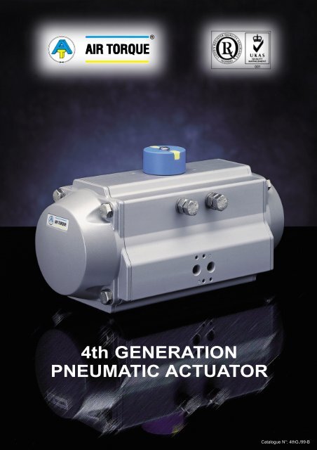
<strong>4th</strong> <strong>GENERATION</strong><br />
<strong>PNEUMATIC</strong> <strong>ACTUATOR</strong><br />
Catalogue N°: <strong>4th</strong>G./99-B
®<br />
DESIGN AND CONSTRUCTION<br />
I N D E X<br />
Title<br />
Page<br />
Design and<br />
construction........................... 2 & 3<br />
Range of options..........................3<br />
Quality manufacturing.................. 3<br />
Accessories available ..................3<br />
Multifunction-Indicator.................. 4<br />
Ancillaries installation<br />
without Multi-function<br />
indicator........................................4<br />
DESIGN<br />
The new <strong>4th</strong> Generation rack and pinion pneumatic actuator has been<br />
designed, developed and tested incorporating the latest technology and<br />
materials available, with some innovativ designe features.<br />
As a result of this product research we have obtained a high grade<br />
product with the following characteristics:<br />
♦ Reliability<br />
♦ High performance<br />
♦ Wider product range permitting a more economical sizing selection<br />
♦ Innovative and patented universal drive shaft and multifunction position indicator<br />
♦ Full compliance with latest worldwide specifications<br />
♦ A wide selection of highest levels of corrosion protection technology<br />
♦ Aesthetically compact and modern style with no external cavities to avoid deposit build up<br />
CONSTRUCTION<br />
100% Travel stop<br />
adjustment....................................4<br />
Lock-Out option............................4<br />
Operating conditions....................5<br />
Operating function........................5<br />
Fast acting operation................... 5<br />
1. Extruded aluminium<br />
body, with both internal<br />
and external corrosion<br />
protection having honed<br />
cylinder surface for longer<br />
life and lower coefficient<br />
of friction.<br />
2. Dual piston rack<br />
and pinion design<br />
for compact<br />
construction, symmetric<br />
mounting position, highcycle<br />
life and fast<br />
operation, reverse rotation<br />
can be accomplished in<br />
the field by simply inverting<br />
the pistons.<br />
3. Two indipendent<br />
external travel stop<br />
adjustments.<br />
Permits an easy and precise<br />
adjustment of +/- 4° in both<br />
directions, in the open and<br />
close positions for an<br />
accurate valve alignment.<br />
Parts and materials......................6<br />
ATB0 dimensions<br />
material and technical<br />
data.............................................. 7<br />
6<br />
Metric dimensions<br />
and technical data........................8<br />
Imperial Dimensions<br />
and technical data........................9<br />
1<br />
9<br />
3<br />
Metric torque outputs..........10 & 11<br />
4<br />
Imperial torque outputs......12 & 13<br />
2<br />
120° and 180°<br />
Actuators....................................14<br />
3 Position Actuators................... 15<br />
Sizing Information..............15 & 16<br />
Protection levels available......... 17<br />
10<br />
13<br />
Full compliance with<br />
worldwide specifications.............18<br />
5<br />
How to order...............................19<br />
Quality product...........................19<br />
Standard<br />
documentation available............ 19<br />
Air Torque Sales<br />
Organization...............................20<br />
4. Universal and<br />
anti-blowout patented<br />
drive shaft for an easy<br />
conversion from parallel<br />
to diagonal square and<br />
vice versa. This feature<br />
permits a lower and more<br />
flexible stock.<br />
5. One compact design<br />
with identical body and<br />
end caps for double acting<br />
and spring return models<br />
reducing inventory and<br />
allowing field conversion,<br />
by adding or removing<br />
modular spring cartridge.<br />
6. Multifunction position<br />
indicator with Namur slot<br />
to allow: visual position<br />
indication, to fit and drive<br />
all accessories, to fit easily<br />
and economically the most<br />
popular sensors.<br />
2<br />
www.valcontrol.pt
®<br />
CONSTRUCTION<br />
7. Multiple bearings<br />
and guides<br />
on racks and pistons for<br />
precise operation, low<br />
friction, high cycle life and<br />
prevent shaft blowout.<br />
8. Modular preloaded<br />
spring cartridge design.<br />
With coated spring for<br />
simple versatile range,<br />
greater safety and<br />
corrosion resistance.<br />
9. Fully machined teeth on<br />
piston rack and pinion for<br />
accurate low backlash<br />
rack and pinion<br />
engagement and<br />
maximum efficiency.<br />
10. Electroless nickel-plated<br />
blowout resistant,<br />
bearing guided one-piece<br />
pinion for improved<br />
safety and maximum<br />
cycle life.<br />
11. Selected high<br />
quality bearings<br />
and seal for low friction,<br />
high cycle life and<br />
a wide operating<br />
temperature range.<br />
6<br />
11<br />
12<br />
8<br />
12. Internal and external<br />
stainless steel fasteners for<br />
long term corrosion<br />
resistance.<br />
7<br />
7<br />
13. Full conformance to<br />
the latest specifications:<br />
ISO 5211, DIN 3337<br />
and VDI/VDE 3845<br />
NAMUR for product<br />
interchangeability<br />
and easy mounting of<br />
solenoids, limit switches<br />
and other accessories.<br />
5<br />
13<br />
RANGE OF OPTIONS, ACCESSORIES AND QUALITY MANUFACTURING<br />
RANGE OF OPTIONS<br />
A. With the <strong>4th</strong> generation actuator we are able to offer 6 different levels of protections A, B, C, D, E, P.<br />
Please see table of protection levels available N° P01/99.<br />
B. Stainless steel 303 or 316 drive shaft is available on request on all sizes and all different protection levels .<br />
C. For high and low temperature applications FPM or Silicon O rings combined with a suitable lubricant are available for all models.<br />
D. 100% Adjustable travel stop.<br />
E. Economical Lock out capability in the fully-open or the fully-closed position.<br />
F. Multifunction Position indicator with S.S. metal inserts for proximity sensing.<br />
G. S.S. drive shaft Cover with namur slot for high temperature application and manual override.<br />
H. Other than the standard Parallel or Diagonal bottom drive shaft connection, we can supply Keyed drive connection, Flat head<br />
connection or special customized connections.<br />
I. 120° and 180° Actuator rotation and intermediate rotations like 135°.<br />
J. 3 position Actuators.<br />
QUALITY MANUFACTURING<br />
♦ The AIR TORQUE actuators are manufactured<br />
under a quality system independently assessed<br />
and approved to ISO 9001.<br />
♦ Every single actuator is factory tested and provided<br />
with a unique serial number for traceablity.<br />
♦ Each individual actuator is packed in a special<br />
proper cardboard carton with a clear and full<br />
description of the product for protection and<br />
easy identification.<br />
ACCESSORIES AVAILABLE<br />
♦ Square drive reduction pieces for all drive shafts<br />
♦ Centering/location ring for all sizes<br />
♦ Brackets<br />
♦ Couplings<br />
♦ Solenoid valves<br />
♦ Switch boxes<br />
♦ Proximity sensors<br />
♦ Gear boxes<br />
♦ Positioners<br />
www.valcontrol.pt<br />
3
®<br />
MULTI-FUNCTION INDICATOR<br />
The multi-function indicator which is supplied as standard on <strong>4th</strong> Generation Actuator and manufactured in composite material is suitable for:<br />
1. Position indication<br />
Visual indication of the Actuator/Valve position is<br />
shown via a color coded insert and Namur slot.<br />
The indicator is suitable for all types of drive<br />
shaft and either direction of actuator rotation.<br />
2. Actuator ancillary drive<br />
The Namur drive slot in the position indicator<br />
permits direct drive engagement<br />
of switchboxes and positioners.<br />
3. Direct mounting of sensors<br />
The indicator can be supplied with metal inserts<br />
to permit easy and economical installation of many<br />
types of sensors: P+F, IFM, TURK, etc.<br />
ANCILLARIES INSTALLATION WITHOUT MULTI-FUNCTION INDICATOR<br />
S.S. Cover insert<br />
with VDI/VDE slot<br />
The <strong>4th</strong> Generation actuator can be supplied upon<br />
request with a S.S. Cover that replaces the standard indicator<br />
and has the Namur drive slot permiting:<br />
1. Fitment of ancillaries such as switchboxes and<br />
positioners<br />
2. Indication of actuator position via the Namur slot<br />
3. Operate at high temperature<br />
4. Manual operation of the actuator in cases of<br />
emergency.<br />
100% TRAVEL STOP ADJUSTMENT ON 4TH <strong>GENERATION</strong> <strong>ACTUATOR</strong><br />
The <strong>4th</strong> Generation standard actuator provides stroke<br />
adjustment of + or - 4° in both directions 0° and 90°.<br />
When a stroke of less than 90° is required e.g. 1°, 5°, 10°,<br />
25°, 50°, 80°, etc. the actuator can be supplied with<br />
special bolts in both End-Caps to allow stroke<br />
adjustment or limitation, from 0° to 90° according to<br />
customer requirements. The 100% TRAVEL STOP<br />
ADJUSTMENT is available on all of the <strong>4th</strong> Generation<br />
actuator range.<br />
Longer screws for 100% stroke adjustment<br />
LOCK-OUT CAPABILITY IN FULLY-OPEN OR FULLY-CLOSED POSITION<br />
The <strong>4th</strong> generation actuator offers an economical<br />
solution when is requested to locking the actuator in the<br />
fully-open (90°) or fully-closed (0°) position. The actuator<br />
can be supplied with a special bolt and locking device<br />
to permanently lock the actuator in position by using a<br />
padlock and preventing unwanted operation.<br />
Special longer bolt, to use only to lock the<br />
actuator in one position when you need.<br />
4<br />
www.valcontrol.pt
OPERATING CONDITIONS<br />
®<br />
1. Operating media:<br />
Dry or lubricated air or inert/non-corrosive gases on condition that<br />
they are compatible with internal actuator parts and lubricant.<br />
The operating media must have a dew point equal to -20°C<br />
(-40F) or at least 10°C below the ambient temperature.<br />
The maximum particle size must not exceed 30 µ.<br />
2. Supply pressure:<br />
For Double Acting and Spring Return actuators the maximum supply<br />
pressure is: 8 Bar (116 PSI). Minimum supply pressure is 2.5 Bar (36 PSI).<br />
5. Operating Time:<br />
See Technical Data Sheet<br />
6. Lubrication:<br />
Actuators are factory lubricated for the life under normal operating<br />
conditions.<br />
The standard lubricant is suitable for use from -20°C (-40F) to +80°C<br />
(+176° F).<br />
For low (LT) and high (HT) temperature service, where special<br />
grease is required please contact AIR TORQUE.<br />
3. Operating Temperature:<br />
* Standard product from -20°C (-4°F) to +80°C (+176°F )<br />
* Low temperature LT actuator with silicon "O'' rings from -40°C<br />
(-40°F) to +80°C (+176° F)<br />
* High temperature HT actuator with FPM "O" rings from -15°C (+5°F)<br />
to +150°C (+300°F)<br />
Caution: For low and high temperature service, special grease is<br />
required. Please contact AIR TORQUE for each application. High<br />
and low temperature will vary the output torque of the actuator.<br />
4. Stroke:<br />
The stroke for AIR TORQUE actuators is as follows (See technical data):<br />
* Standard construction: 90° rotation with stroke adjustment at 0°<br />
and 90° + or - 4°<br />
* Type Y 120° stroke: 120° rotation with stroke adjustment at 0° and<br />
120° + or - 4°<br />
* Type X 180° stroke: 180° rotation with stroke adjustment at 0° and<br />
180° + or - 4°.<br />
OPERATING FUNCTION AND DIRECTION OF ROTATION<br />
7. Construction:<br />
Twin piston rack and pinion actuator design suitable for both indoor<br />
and outdoor installation.<br />
9. Actuator designation and Marking:<br />
The actuator type, size, operating pressure, output torque, direction of<br />
rotation, orientation of failure mode, operating temperature and drive<br />
type are determined by actuator designation. AIR TORQUE actuators<br />
are supplied with a label showing all this informations: type, model<br />
(including protection and if applicable the LT or HT for operating<br />
temperature), stroke, maximum permissible supply pressure, direction<br />
of rotation, output torque, ancillary mounting detail, pressure connection,<br />
actuator/valve mounting detail and serial number.<br />
The standard rotation is clockwise to close, counter-clockwise rotation is achieved when port 2 is pressurised.<br />
For actuator marked LF the rotation is counter-clockwise to close, clockwise rotation is obtained when port 2 is pressurised<br />
Double Acting operation function (standard rotation) TOP View:<br />
8. Protection and Corrosion resistance:<br />
Actuators are supplied with corrosion protections for normal<br />
environments. For severe duties select from the protection level<br />
table or contact AIR TORQUE.<br />
Air supplied to<br />
Port 2 forces the<br />
pistons apart<br />
and towards the<br />
actuators end<br />
caps, with the<br />
exhaust air exiting<br />
at Port 4, a<br />
counter-clockwise<br />
rotation is<br />
achieved.<br />
Air supplied to<br />
Port 4 forces the<br />
pistons together<br />
with exhaust air<br />
exiting at Port 2,<br />
a clockwise<br />
rotation is<br />
achieved.<br />
"2" "4"<br />
"2" "4"<br />
Single Acting operation function (standard rotation) TOP View:<br />
Air supplied to<br />
Port 2 forces the<br />
pistons apart and<br />
toward the actuator<br />
end caps,<br />
compressing the<br />
springs with the<br />
exhaust air existing<br />
at Port 4, a<br />
counter clockwise<br />
rotation is<br />
achieved.<br />
"2"<br />
"4"<br />
On loss of air pressure<br />
(air or electric<br />
failure) at Port 2<br />
allows the springs to<br />
force the pistons<br />
together with the<br />
exhaust air exiting<br />
at Port 2, a<br />
clockwise rotation is<br />
achieved.<br />
"2"<br />
"4"<br />
FAST ACTING <strong>ACTUATOR</strong>S<br />
Upon request AIR TORQUE actuators can be specially manufactured for fast acting operations. The normal life span of the<br />
actuators is associated with the normal operating time.<br />
www.valcontrol.pt<br />
5
®<br />
PARTS AND MATERIALS<br />
05*<br />
50 41 08* 10 18 39 19 30<br />
02<br />
17<br />
13<br />
42<br />
31<br />
08*<br />
01<br />
21*<br />
06*<br />
60<br />
04<br />
03<br />
11*<br />
14*<br />
15*<br />
16*<br />
40<br />
12<br />
09*<br />
07*<br />
20*<br />
43<br />
Suggested SPARE PARTS For maintenance (A) For other protection levels available see page 17<br />
6<br />
www.valcontrol.pt
N<br />
I<br />
ATB0 DIMENSIONS,<br />
MATERIAL AND TECHNICAL DATA<br />
®<br />
øZ<br />
39<br />
M<br />
L<br />
P<br />
19<br />
18<br />
08a<br />
08<br />
21<br />
04<br />
16<br />
13<br />
09<br />
12<br />
Square C<br />
Detail " X "<br />
14<br />
11<br />
10<br />
03<br />
02<br />
11a<br />
22<br />
41<br />
05<br />
øH Detail " Y "<br />
01<br />
B<br />
A<br />
M6xO<br />
TOP VIEW<br />
M5xD<br />
CH<br />
45°<br />
BOTTOM VIEW<br />
G1/8" ISO228-1<br />
M5xE<br />
PORT '4'<br />
45°<br />
G<br />
Q<br />
W<br />
S<br />
R<br />
h<br />
PORT '2'<br />
F<br />
Diagonal Square<br />
Parallel Square<br />
Detail "X"<br />
Detail "Y"<br />
Suggested SPARE PARTS For maintenance (A) For other protection levels available see page 17<br />
obviously on the field applications when one or more of the above parameter are different, the moving time will<br />
be different.<br />
www.valcontrol.pt<br />
7
I<br />
®<br />
METRIC DIMENSIONS<br />
AND TECHNICAL DATA<br />
"Model AT700"<br />
C<br />
øZ<br />
4<br />
PORT '2'<br />
PORT '4'<br />
0<br />
X<br />
B<br />
B<br />
P<br />
T - Connection<br />
L<br />
M<br />
Detail " X "<br />
A<br />
VDI/VDE 3845<br />
M5xE<br />
BOTTOM VIEW - ISO 5211<br />
D<br />
G<br />
4<br />
C<br />
h<br />
Detail " Y "<br />
H<br />
Detail " Y "<br />
L<br />
M<br />
N<br />
CH<br />
45°<br />
R<br />
Q1<br />
S<br />
Detail " X "<br />
M6x12<br />
Q<br />
45°<br />
W<br />
W1<br />
F<br />
Diagonal Square<br />
Parallel Square<br />
53 64<br />
Notes:<br />
(A) The above indicated moving time of the actuator, are obtained in the following test conditions: (1) Room Temperature, (2) Actuator Stoke 90°, (3) Solenoid Valve with Orifice Of 4 mm and a flow capacity Qn 400 L/min.,<br />
(4) Inside pipe diameter 8 mm, (5) Medium clean air, (8) Air supply pressure 5,5 bar (79,75Psi), (7) Actuator without external resistance load.<br />
Cautions: obviously on the field applications when one or more of the above parameter are different, the moving time will be different.<br />
8<br />
www.valcontrol.pt
I<br />
IMPERIAL DIMENSIONS<br />
AND TECHNICAL DATA<br />
®<br />
"Model AT700"<br />
C<br />
øZ<br />
4<br />
PORT '2'<br />
PORT '4'<br />
X<br />
0<br />
B<br />
B<br />
P<br />
L<br />
M<br />
Detail " X "<br />
A<br />
T - Connection<br />
VDI/VDE 3845<br />
M5xE<br />
BOTTOM VIEW - ISO 5211<br />
D<br />
G<br />
4<br />
C<br />
h<br />
Detail " Y "<br />
Detail " Y "<br />
L<br />
M<br />
H<br />
N<br />
CH<br />
45°<br />
R<br />
Q1<br />
S<br />
Detail " X "<br />
M6x12<br />
Q<br />
45°<br />
W<br />
W1<br />
F<br />
Diagonal Square<br />
Parallel Square<br />
115 139<br />
Notes: (A) (A) The The above above indicated indicated moving moving time of the time actuator, of the are actuator, obtained in are the obtained following in test the conditions: following (1) test Room conditions: Temperature, (1)(2) Room Actuator Temperature, Stoke 90°, (3)(2) Solenoid Actuator Valve Stoke with Orifice 90°, Of (3) Solenoid Valve with Orifice Of 4 mm and a flow capacity Qn 400 L/min.,<br />
4 mm and a flow capacity Qn 400 L/min., (4) Inside pipe diameter 8 mm, (5) Medium clean air, (8) Air supply pressure 5,5 bar (79,75Psi), (7) Actuator without external resistance load.<br />
(4) Inside pipe diameter 8 mm, (5) Medium clean air, (8) Air supply pressure 5,5 bar (79,75Psi), (7) Actuator without external resistance load.<br />
Cautions: obviously on the field applications when one or more of the above parameter are different, the moving time will be different.<br />
www.valcontrol.pt<br />
9
®<br />
METRIC TORQUE RATINGS<br />
Out-put torque<br />
available when<br />
air supply fails<br />
10<br />
www.valcontrol.pt
®<br />
METRIC TORQUE RATINGS<br />
Out-put torque<br />
available when<br />
air supply fails<br />
Torque Torque Torque<br />
www.valcontrol.pt<br />
11
®<br />
IMPERIAL TORQUE RATINGS<br />
Out-put torque<br />
available when<br />
air supply fails<br />
12<br />
www.valcontrol.pt
®<br />
IMPERIAL TORQUE RATINGS<br />
Out-put torque<br />
available when<br />
air supply fails<br />
Star<br />
End<br />
Torque Torque Torque<br />
90°<br />
www.valcontrol.pt<br />
13
I<br />
®<br />
TECHNICAL DATA FOR 120°<br />
AND 180° <strong>ACTUATOR</strong>S IN METRIC AND IMPERIAL<br />
DIMENSIONS<br />
øZ<br />
4<br />
4<br />
C<br />
VDI/VDE 3845<br />
h<br />
D<br />
PORT '2'<br />
PORT '4'<br />
R<br />
0<br />
X<br />
B<br />
P<br />
Detail " Y "<br />
S<br />
Detail " X "<br />
Detail " X "<br />
A - 120°<br />
A - 180°<br />
T - Connection<br />
Detail " Y "<br />
L<br />
M<br />
H<br />
N<br />
M5xE<br />
BOTTOM VIEW - ISO 5211<br />
45°<br />
CH<br />
G<br />
Q1<br />
45°<br />
M6x12<br />
Q<br />
W<br />
W1<br />
Cautions: obviously on the field applications when one or more of the above parameter are different, the moving time will be different.<br />
F<br />
Diagonal Square<br />
Parallel Square<br />
Notes:<br />
(A) The above indicated moving time of the actuator, are obtained in the following test conditions: (1) Room Temperature, (2) Actuator Stoke 120° and 180°, (3) Solenoid Valve with Orifice Of 4 mm and a flow capacity<br />
Qn 400 L/min., (4) Inside pipe diameter 8 mm, (5) Medium clean air, (8) Air supply pressure 5,5 bar (79,75Psi), (7) Actuator without external resistance load.<br />
Cautions: obviously on the field applications when one or more of the above parameter are different, the moving time will be different.<br />
♦120 and 180° actuator are available only in double acting version<br />
♦ther actuator sizes (ex. AT 350 180°) would be evaluated on request<br />
♦Different Actuator strokes other than 120° and 180° (e.g. 135 Stoke) are available on request.<br />
14<br />
www.valcontrol.pt
®<br />
3 POSITION <strong>ACTUATOR</strong><br />
AIR TORQUE 3 position pneumatic actuator provide an operation of 0°- 45°- 90° or 0°-90°-180°. The intermediate position is<br />
achieved by a mechanical stop of movement on the 2 auxiliary pistons. This intermediate stop positions adjustable e.g. 90°<br />
actuators can provide 20° 30° 50° 75° etc.<br />
In order to control the operation of AT 3 position pneumatic actuators a system of solenoid valves controlling a sequence of<br />
air supplies to the actuator is required as described below:<br />
"D" "C" "2" "4" "C"<br />
"D"<br />
Position 1 (Intermediate Position):<br />
This position is achieved when air is supplied simultaneously<br />
to ports 2 and D with exhaust air at ports 4 and C. In fact<br />
the air supplied at ports D forces the auxiliary pistons to the<br />
center and the rods serve as mechanical stops for the<br />
internal pistons in the desired intermediate position.<br />
Position 2 (Fully Open Position):<br />
This position is achieved when air is supplied to port 2<br />
and port C (Air to port C may also be avoided) with<br />
exhaust air at port 4. In this condition air to port 2 permit<br />
to internal pistons to continue the opening stroke.<br />
"D" "C" "2" "4" "C"<br />
"D"<br />
Position 3 (Fully closed Position):<br />
This position is obtained when air is supplied to port 4<br />
with exhaust air at port 2.<br />
"D"<br />
"C"<br />
"2"<br />
"4"<br />
SIZING INFORMATION<br />
"C"<br />
"D"<br />
The aim of this information is to assist in the correct selection of AIR TORQUE actuators. Before fitting an AT actuator onto any<br />
valve the following data must be considered:<br />
• breakaway torque of the valve + safety factor as recommended by the manufacturer/considering the operating conditions.<br />
• air supply pressure available to the actuator<br />
• type of actuator “D” (double acting) or “S” (spring return) and output torque of actuator at the available air supply pressure<br />
• actuator rotation and the fail mode(to fail open or to fail close)<br />
The correct selection of an actuator is critical, if the actuator is oversized the valve stem can be overstressed, on the contrary<br />
if the actuator is undersized it cannot produce enough torque to permit full valve operation.<br />
Generally we can say that the torque required for valve operation comes from the friction between the metallic parts of the<br />
valve (for example ball or disc) and the seals (seats).<br />
Moreover the torque is influenced by variours factors depending on the type of application of the valve (service condition):<br />
service temperature, operation frequency, line and differential pressure, flow media (lubricated, dry or slurry).<br />
The following examples show the torque characteristic for 3 types of quarter-turn valves: ball valve, butterfly valve and plug valve.<br />
BALL VALVE<br />
Ball valve concept of construction is based<br />
essentially on a polished ball (including a<br />
through port) contained between two<br />
seats (upstream and downstream). The ball<br />
rotation allows the flow or stops the flow<br />
through the valve. Differential of pressure<br />
between upstream and downstream<br />
pressure forces the ball against the<br />
downstream seat (floating ball design).<br />
In this case the valve torque is generated<br />
by the friction between the ball,<br />
seat,stem and packing.<br />
As shown in the diagram below the<br />
highest point of torque occurs when with<br />
the presence of pressure, and the ball in<br />
the closed position, the valve is moved<br />
to the open position (breakaway torque).<br />
BALL VALVE TORQUE<br />
BUTTERFLY VALVE<br />
Butterfly valve concept of construction is<br />
based essentially on a disc fixed on an axis.<br />
In the closed position the disc is completely<br />
contained by the seat. The open position is<br />
achieved when the disc is rotated (through<br />
its stem) becomes parallel to the flow.<br />
On the contrary, the closed position is<br />
achieved when the disc is perpendicular to<br />
the flow. With a butterfly valve the torque is<br />
generated by the friction between the disc,<br />
seat and the stem packing. Also torque<br />
may be effected by the differential pressure<br />
that forces on the disc. The highest point<br />
of torque, as shown in the diagram below,<br />
is in the closed position, and after<br />
only a small rotation torque is considerably<br />
reduced.<br />
BUTTERFLY VALVE TORQUE<br />
PLUG VALVE<br />
Plug valve concept construction is based<br />
essentially on a male (plug) contained in<br />
a female cone (seat). The plug provides<br />
a through port in one direction and with<br />
its rotation into the seat the opening and<br />
closure of the valve is achieved.<br />
The torque is usually not influenced by the<br />
flow pressure, but is generated essentially<br />
by the friction between the seat and the<br />
plug, during the opening + closing cycle.<br />
the highest point of torque as shown in<br />
the diagram below, occurs in the closed<br />
position and remains high for the rest<br />
of the operation, because the torque<br />
is not influenced by pressure.<br />
PLUG VALVE TORQUE<br />
100%<br />
70-80%<br />
100%<br />
100%<br />
80-90%<br />
25-30%<br />
15-20%<br />
Torque %<br />
T<br />
Torque %<br />
Torque %<br />
CLOSE<br />
Valve Rotation<br />
OPEN<br />
CLOSE<br />
Valve Rotation<br />
OPEN<br />
CLOSE<br />
Valve Rotation<br />
OPEN<br />
www.valcontrol.pt<br />
15
®<br />
SIZING: DOUBLE ACTING <strong>ACTUATOR</strong><br />
With rack and pinion construction the output torque of an actuator is obtained<br />
by multiplying the piston force (given by air supply pressure) by the<br />
pitch shaft radius (lever arm) as shown in fig. 1 less the force lost for friction<br />
(efficiency). Because of this concept, the output torque is linear as shown in<br />
the diagram A in both clockwise and counterclockwise rotation.<br />
The suggested safety factor for double acting actuators in normal working<br />
conditions is 15-20%.<br />
fig.1<br />
PITCH<br />
RADIUS<br />
(LEVER<br />
OR ARM)<br />
TORQUE<br />
FORCE<br />
PRESSURE<br />
Torque Nm<br />
DOUBLE ACTING TORQUE<br />
diag. A<br />
Actuator Torque<br />
0° Actuator Rotation 90°<br />
Sizing example of Double Acting AT actuator (see also technical data):<br />
• Published butterfly valve torque = 40Nm<br />
• Safety factor (20%) = 40 Nm + 20% = 48 Nm<br />
• Air supply pressure available = 5 bar<br />
The double acting AT actuator that produces a minimum of 48 Nm at 5 bar is AT200<br />
(see also the diagram B).<br />
diag. B<br />
48 Nm<br />
SAFETY FACTOR<br />
40 Nm<br />
Torque Nm<br />
<strong>ACTUATOR</strong> SELECTION<br />
DOUBLE ACTING EXAMPLE<br />
AT200 DA TORQUE AT 5 BAR<br />
8 Nm<br />
VALVE TORQUE<br />
0° Actuator Rotation 90°<br />
Closed valve<br />
Opened valve<br />
SIZING: SPRING RETURN <strong>ACTUATOR</strong><br />
In spring return applications the output torque is obtained in two different operations as shown in fig. 2 and 3. Each operation<br />
produces two different values in relation to the stroke position (0° or 90°). For spring return actuators the output torque is produced<br />
by multiplying the force (air or springs acting on the pistons) by the lever arm.<br />
First condition (fig. 2): output torque is generated by air supply pressure at<br />
Port 2 after compressing the springs, called “OUTPUT TORQUE AIR<br />
STROKE”. In this case air forces the pistons from the 0° to the 90° position<br />
and consequently the torque starts from a high value and during the<br />
stroke it constantly decreases until 90° due to the natural force that<br />
springs generate (oppose) when they are compressed (see diagram C).<br />
fig.2<br />
PITCH<br />
RADIUS<br />
(LEVER<br />
OR ARM)<br />
TORQUE<br />
PRESSURE<br />
FORCE<br />
Torque Nm<br />
AIR STROKE (OUTPUT TORQUE)<br />
diag. C<br />
Air Stroke<br />
0° Actuator Rotation 90°<br />
Second condition (fig. 3): output torque is generated by the force that<br />
springs release onto the pistons when air fails, called “OUTPUT TORQUE SPRING<br />
STROKE”. In this case the torque, starting from the 90° position, constantly<br />
decreases until 0° because of springs extending (see diagram D).<br />
fig.3<br />
PITCH<br />
RADIUS<br />
(LEVER<br />
OR ARM)<br />
TORQUE<br />
FORCE<br />
SPRINGS<br />
FORCE<br />
SPRING STROKE (OUTPUT TORQUE)<br />
Torque Nm<br />
diag. D<br />
Spring Stroke<br />
0° Actuator Rotation 90°<br />
AT spring return actuator are designed to produce a balanced torque in the<br />
two conditions explained above when the number of springs per side is equal<br />
to the air pressure supply (4 bar - 4 springs each side) as shown in diagram E.<br />
For certain applications it is possible to achieve (where desired), the unbalanced<br />
torque, as shown in diagram F, by changing the relation between<br />
the number of springs per side and air pressure supply in bar (for example 6<br />
springs and 5.5 bar or vice versa).<br />
In spring return applications two conditions can be achieved: air failure to<br />
close or air failure to open. The suggested safety factor for spring return<br />
actuators in normal working conditions is 20-25%.<br />
Torque Nm<br />
BALANCED TORQUE<br />
diag. E<br />
Air Stroke<br />
Spring Stroke<br />
0° Actuator Rotation<br />
90°<br />
Torque Nm<br />
UNBALANCED TORQUE<br />
diag. F<br />
Air Stroke<br />
Spring Stroke<br />
0° Actuator Rotation 90°<br />
Sizing example of AT Spring Return actuator (see also technical data):<br />
Spring to close (when air fails)<br />
• Published ball valve torque = 80 Nm<br />
• Safety factor (20%) = 80 Nm + 20% = 96 Nm<br />
• Air supply pressure available = 5 bar<br />
diag.G<br />
172 Nm<br />
105 Nm<br />
Air Stroke<br />
Spring Stroke<br />
165 Nm<br />
112 Nm<br />
The spring return AT actuator selected is AT400 S10, because it produces<br />
the following values:<br />
• spring stroke 0° = 105 Nm<br />
• spring stroke 90° = 165 Nm<br />
• air stroke 0° = 172 Nm<br />
• air stroke 90° = 112 Nm<br />
(See also the diagram G).<br />
96 Nm<br />
80 Nm<br />
Torque Nm<br />
0°<br />
Closed valve<br />
( Air failure )<br />
Safety Factor<br />
Valve Torque<br />
Actuator Rotation<br />
77 Nm<br />
64 Nm<br />
90°<br />
Opened valve<br />
16<br />
www.valcontrol.pt
Components<br />
Body<br />
End-caps<br />
Drive shaft<br />
Pistons<br />
Suitable for:<br />
Not recommended for:<br />
Salt Spray Test Certif. N°<br />
PROTECTIONS LEVELS FOR<br />
<strong>4th</strong> <strong>GENERATION</strong> <strong>ACTUATOR</strong><br />
A<br />
Alodur (Special hard anodized)<br />
Colour:<br />
Bright Stainless steel<br />
Chromatized + Polyester Coated<br />
Colour:<br />
S.S. Ral 9007 or Blue Ral 5015<br />
Carbon Steel ENP<br />
Normal Anodized<br />
Colour:<br />
Black<br />
-General service<br />
Caustic Soda<br />
-All strong acids or basic solutions<br />
SAC/655/98<br />
PROTECTION LEVELS AVAILABLE<br />
Alodur + PTFE coating<br />
B<br />
Colour:<br />
Light grey<br />
Chromatized + Polyester Coated<br />
Colour:<br />
S.S. Ral 9007 or Blue Ral 5015<br />
Carbon Steel ENP<br />
Normal Anodized<br />
Colour:<br />
Black<br />
-General service<br />
-Acids or basic solutions in low<br />
concentration<br />
-Nitric acid<br />
-N-Methyle Pirolidone (solvent)<br />
SAC/656/98<br />
C<br />
ENP+ Polyester transparent Coated<br />
Colour:<br />
Bright Stainless steel<br />
Chromatized + Polyester Coated<br />
Colour:<br />
S.S. Ral 9007<br />
Carbon Steel ENP<br />
Normal Anodized<br />
Colour:<br />
Black<br />
-General service<br />
-Caustic soda in low concentration<br />
Nitric acid<br />
-Chlorine, sulphuric and salted<br />
enviroment<br />
SAC/892/96<br />
®<br />
Kesternick Test Certif. N°<br />
SAC/299/98<br />
SAC/300/98<br />
SAC/895/96<br />
ENP= Electroless nickel<br />
coating<br />
High Phosforous<br />
content P>10%<br />
Components<br />
Alodur + PTFE coating<br />
D<br />
PROTECTION LEVEL<br />
Alodur + PTFE coating<br />
E<br />
P<br />
Alodur (special hard anodized)<br />
Body<br />
Colour:<br />
Light grey<br />
Chromatized + PTFE coating<br />
Colour:<br />
Light grey<br />
Chromatized + PTFE coating<br />
Colour:<br />
Bright Stainless steel<br />
Resin Impregnated + Hard Anodized<br />
End-caps<br />
Drive shaft<br />
Pistons<br />
Suitable for:<br />
Not recommended for:<br />
Colour:<br />
Light grey<br />
Carbon Steel ENP<br />
Normal Anodized<br />
Colour:<br />
Black<br />
-General service<br />
-Acids or basic solutions in low<br />
concentration<br />
-Nitric acid<br />
-N-Methyle Pirolidone (solvent)<br />
Colour:<br />
Light grey<br />
S.S. 303 (Option 316)<br />
Normal Anodized<br />
Colour:<br />
Black<br />
-General service<br />
-Acids or basic solutions in low<br />
concentration<br />
-Nitric acid<br />
-N-Methyle Pirolidone (solvent)<br />
Colour:<br />
Dark gray<br />
Carbon Steel ENP<br />
Normal Anodized<br />
Colour:<br />
Black<br />
-General service<br />
Suggested for any kind of solvent<br />
-Caustic soda<br />
-All stong acids or basic solutions<br />
Salt Spray Test Certif. N°<br />
SAC/890/96<br />
SAC/886/96<br />
SAC/304/98<br />
Kesternick Test Certif. N°<br />
SAC/896/96<br />
SAC/897/96<br />
SAC/301/98<br />
ENP= Electroless nickel<br />
coating<br />
High Phosforous<br />
content P>10%<br />
www.valcontrol.pt<br />
17
®<br />
FULL COMPLIANCE WITH<br />
WORLDWIDE SPECIFICATIONS<br />
AIR TORQUE <strong>4th</strong> Generation actuator are designed in full compliance with the latest worldwide specifications relating to the<br />
actuator accessory and valve mounting interfaces.<br />
Bottom mounting pad (Actuator to valve interface) configurated in accordance with ISO 5211 and DIN 3337 specifications<br />
♦ ISO 5211 and DIN 3337<br />
configuration permits<br />
easy installation of the<br />
actuator directly onto a<br />
valve or will interface<br />
through an ISO bracket.<br />
ISO gear boxes.<br />
♦ AIR TORQUE can supply<br />
all mountig kits i.e.<br />
Assorted Square drive<br />
reducer pieces suitable<br />
for all square drive shaft,<br />
Centering rings for all<br />
sizes, Brackets and<br />
Couplings.<br />
Other than the standard<br />
bottom ISO/DIN Parallel<br />
or Diagonal square output<br />
on the drive shaft<br />
connection, we can supply<br />
a Keyed connection, Flat<br />
head connection or special<br />
customized drive<br />
connections.<br />
Top mounting pad configuration is in accordance with VDI/VDE 3845 Namur specification in order to permit simple and easy<br />
installation of the ancillary like switch boxes and positioners. AIR TORQUE can supply many different types of switchboxes and<br />
positioners for any application.<br />
Air supply connection is in accordance with VDI/VDE 3845 Namur specification to provide simple and easy solenoid valve<br />
installation, direct mount avoiding piping and fittings. AIR TORQUE can also supply Namur solenoid valves: 5/2 and 3/2 way in<br />
all standard voltages, D.C. or A.C.<br />
2 4<br />
2<br />
3<br />
1<br />
5<br />
3<br />
1<br />
5/2 SOLENOID<br />
VALVE OPERATION<br />
3/2 SOLENOID<br />
VALVE OPERATION<br />
18<br />
www.valcontrol.pt
HOW TO ORDER<br />
<strong>4th</strong> <strong>GENERATION</strong> <strong>ACTUATOR</strong>S<br />
®<br />
NOTES:<br />
(1) Standard Rotation for double acting and spring return is Clockwise to close (for double acting when port 4 is pressurised).<br />
(2) When the Centerring (Spigot) is requested the letter Y must be added after the flange tipe. Example F07Y.<br />
(3) Standard Square is diagonal square, when parallel square is requested a letter L must be added after the square dimension. Example 22L<br />
Other type of shaft connection like different square size. Flat head and Keyed bore are available and need a detailed description.<br />
(4) When indicator for Proximity is requested it must be indicated with letter P. If not specified the actuators will be supplied with standard Position indicator.<br />
Example 1: AT300 D A F07 Y 17<br />
Description: Actuator Model AT300, Type Double Acting (clockwise to close),Protection A, with Flange F07 plus centerring, with diagonal square of 17 mm, with<br />
standard indicator and standard NBR seals.<br />
Example 2: AT550 So 10 B F14 36L P HT<br />
Description: Actuator Model AT550, Type Spring return (Spring to open),with 10 springs (5 per side), Protection B, with Flange F14, with Parallel square of 36 mm,<br />
with indicator for proximity and FPM seals for high temperature.<br />
QUALITY PRODUCT<br />
♦ Each individual actuator is factory inspected and tested.<br />
♦ Each individual actuators are supplied with certificate of Conformity.<br />
♦ Each individual actuator has a serial number for full traceability.<br />
♦ Each individual actuator is individually packed in a special cardboard carton for protection, with a product description<br />
label for easy identification and includes installation, operation and maintenance instructions in 5 languages.<br />
Cad system for Design<br />
Controlled Honing of<br />
the internal surface<br />
Electronic torque<br />
test machine<br />
The AIR TORQUE actuators are manufactured to a quality system independently assessed and<br />
approved to ISO 9001.<br />
AVAILABLE STANDARD DOCUMENTATIONS<br />
♦ Company profile<br />
♦ Catalogue <strong>4th</strong>G. /99<br />
♦ Catalogue <strong>4th</strong>G.-R /99<br />
♦ Manual Instruction IMAT4G01/99<br />
♦ Technical data sheet<br />
♦ Corrosion test certificates<br />
www.valcontrol.pt<br />
19
Valcontrol-Válvulas de control e Equipamentos industriais, Lda.<br />
Rua da Guarda, 635 - Perafita<br />
Ap.3060 - 4451-801 Leça da Palmeira<br />
T.229962916 - F.229962919<br />
geral@valcontrol.pt - www.valcontrol.pt


