Product Data Sheet SF155-S - SolarClarity
Product Data Sheet SF155-S - SolarClarity
Product Data Sheet SF155-S - SolarClarity

Create successful ePaper yourself
Turn your PDF publications into a flip-book with our unique Google optimized e-Paper software.
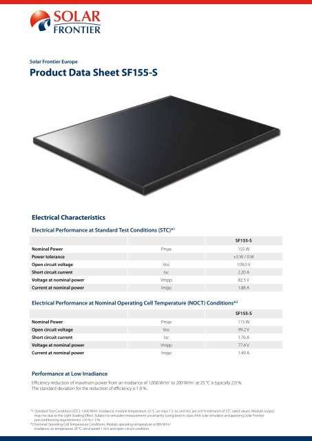
Solar Frontier Europe<br />
<strong>Product</strong> <strong>Data</strong> <strong>Sheet</strong> <strong>SF155</strong>-S<br />
Electrical Characteristics<br />
Electrical Performance at Standard Test Conditions (STC)* 1<br />
<strong>SF155</strong>-S<br />
Nominal Power Pmax 155 W<br />
Power tolerance<br />
+5 W / 0 W<br />
Open circuit voltage Voc 109.0 V<br />
Short circuit current Isc 2.20 A<br />
Voltage at nominal power Vmpp 82.5 V<br />
Current at nominal power Impp 1.88 A<br />
Electrical Performance at Nominal Operating Cell Temperature (NOCT) Conditions* 2<br />
<strong>SF155</strong>-S<br />
Nominal Power Pmax 115 W<br />
Open circuit voltage Voc 99.2 V<br />
Short circuit current Isc 1.76 A<br />
Voltage at nominal power Vmpp 77.4 V<br />
Current at nominal power Impp 1.49 A<br />
Performance at Low Irradiance<br />
Efficiency reduction of maximum power from an irradiance of 1,000 W/m 2 to 200 W/m 2 at 25 °C is typically 2.0 %.<br />
The standard deviation for the reduction of efficiency is 1.9 %.<br />
*1 Standard Test Conditions (STC): 1,000 W/m 2 irradiance, module temperature 25 °C, air mass 1.5. Isc and Voc are ±10 % tolerance of STC rated values. Module output<br />
may rise due to the Light Soaking Effect. Subject to simulator measurement uncertainty (using best-in-class AAA solar simulator and applying Solar Frontier<br />
preconditioning requirements): +10 % / -5 %.<br />
*2 Nominal Operating Cell Temperature Conditions: Module operating temperature at 800 W/m 2<br />
irradiance, air temperature 20 °C, wind speed 1 m/s and open circuit condition.
Typical I-V Characteristics at STC<br />
I-V P-V Characteristics by Irradiance<br />
Model: <strong>SF155</strong>-S<br />
Condition: AM 1.5 / 25 °C<br />
2.50<br />
250<br />
1,000 W/m 2<br />
2.00<br />
200<br />
800 W/m 2<br />
Current [A]<br />
1.50<br />
1.00<br />
2.50<br />
600 W/m 2<br />
400 W/m 2<br />
1,000 W/m 2<br />
I-V P-V Characteristics by Irradiance<br />
Model: <strong>SF155</strong>-S<br />
Condition: AM 1.5 / 25 °C<br />
150<br />
100<br />
250<br />
Power [ W ]<br />
2.00<br />
0.50<br />
200 W/m 2<br />
800 W/m 2<br />
200<br />
50<br />
Current [A]<br />
0.00 1.50<br />
1.00<br />
150 0<br />
0<br />
600 W/m 2<br />
20 40 60 80 100 120<br />
Voltage [V]<br />
400 W/m 2<br />
100<br />
Typical characteristics<br />
Power [ W ]<br />
200 W/m<br />
Thermal 0.50 Characteristics<br />
2<br />
I-V Characteristics by Temperature<br />
50<br />
Model: <strong>SF155</strong>-S<br />
NOCT Condition: AM 1.5 / 1,000 W/m 2<br />
47 °C<br />
Temperature 3.00<br />
0.00 coefficient of Isc<br />
0 +0.01 %/K<br />
0 20 40 60 80 100 120<br />
Temperature coefficient of Voc<br />
-0.30 %/K<br />
Temperature<br />
2.50<br />
coefficient of Pmax Voltage [V]<br />
-0.31 %/K<br />
These thermal characteristics are typical data.<br />
Typical characteristics<br />
Current [A]<br />
Current [A]<br />
2.00<br />
1.50<br />
3.00<br />
1.00<br />
2.50<br />
0.50<br />
2.00<br />
0.00<br />
1.50<br />
1.00<br />
0.50<br />
I-V Characteristics by Temperature<br />
Model: <strong>SF155</strong>-S<br />
Condition: AM 1.5 / 1,000 W/m 2<br />
75 °C<br />
50 °C<br />
25 °C<br />
0 °C<br />
0 20 40 60 80 100 120 140<br />
75 °C<br />
50 °C<br />
25 °C<br />
0 °C<br />
Voltage [V]<br />
Typical characteristics<br />
0.00<br />
0 20 40 60 80 100 120 140<br />
Voltage [V]<br />
Typical characteristics
Characteristics for System Design<br />
Maximum system voltage Vsys 1,000 V DC (UL 600 V DC)<br />
Limiting reverse current Ir 7 A<br />
Maximum series fuse rating Isf 4 A<br />
Mechanical Characteristics<br />
Dimensions (L x W x H)* 3<br />
Weight<br />
1,257 x 977 x 35 mm (49.5 x 38.5x 1.4 inch)<br />
20 kg (44.1 lbs)<br />
Module operating temperature -40 °C to 85 °C<br />
Application class on IEC61730<br />
Fire safety class on IEC61730<br />
Safety class on IEC61140<br />
Snow load (to the front of the module)* 4<br />
Wind load (to the back of the module)<br />
Cell type<br />
Front cover<br />
Encapsulant<br />
Back sheet<br />
Frame<br />
Edge sealant<br />
Junction box<br />
Adhesive<br />
Output cables (Conductor)<br />
Cable lengths (symmetrical)<br />
Connectors<br />
Class A<br />
Class C<br />
II<br />
2,400 Pa (IEC61646) / 1,600 Pa design load (UL1703)<br />
2,400 Pa (IEC61646) / 1,600 Pa design load (UL1703)<br />
CIS substrate glass (cadmium free)<br />
Clear tempered glass, 3.2 mm<br />
EVA<br />
Weatherproof plastic film (color: black & silver)<br />
Anodized aluminum alloy (color: black)<br />
Butyl rubber<br />
Protection rating: IP67 (with bypass diode)<br />
Silicone<br />
2.5 mm 2 / AWG14 (halogen free)<br />
1,200 mm (47.2 inch)<br />
MC4 compatible<br />
Qualifications and Compliance<br />
IEC 61646 / IEC 61730 / UL 1703 / MCS 005-2.3<br />
CE-Mark declaration<br />
ISO 9001 / ISO 14001<br />
No conflict with RoHS<br />
*3: Dimensional tolerances are stated in the drawing section of this product data sheet.<br />
*4: UL - 1.5 times design load is applied to the module. Accordingly, 2,400 Pa (50.1 lbs /ft 2 ) is loaded to test the 1,600 Pa (33.4 lbs /ft 2 ) UL design load.
Module drawing<br />
(7) 20<br />
1,257 ±2<br />
(7) 20<br />
90 (444)<br />
120<br />
DAB12-0039<br />
35 ±0.5 977 ±2<br />
(548.5)<br />
120<br />
431.5 ±5<br />
440 ±5<br />
454.5<br />
454.5<br />
31 ±1 225 372.5 372.5<br />
225 31 ±1<br />
431.5 ±5<br />
2 x ø 4 2 x Grounding<br />
440 ±5<br />
Mounting holes Mounting holes<br />
454.5<br />
454.5<br />
31 ±1 225 372.5 372.5<br />
225 31 ±1<br />
2 x ø 4 2 x Grounding<br />
598.5 ±5<br />
No. Item QT‘Y Description<br />
1 Cell 1 CIS (Substrate glass)<br />
2<br />
465<br />
Cover glass 1 Clear tempered glass<br />
3 Encapsulant EVA<br />
4 Back sheet Weatherproof plastic film / Color: black & silver<br />
5 Frame 1 Set Anodized aluminium alloy / Color: black<br />
6 Edge sealant Butyl rubber<br />
7 Junction box 1 With bypass diode<br />
(28.2)<br />
4 x ø 8.5 8 x ø 6.6<br />
440 ±5<br />
33.5<br />
454.5<br />
454.5<br />
86.6 1,200 ±100<br />
5 372.5 (50) 372.5 150 225 31 ±1<br />
2 x ø 4 2 x Grounding<br />
0<br />
431.5 ±5<br />
598.5 ±5<br />
465 ±5<br />
90 (444)<br />
35 ±0.5 977 ±2<br />
(548.5)<br />
598.5 ±5<br />
65<br />
1,257 ±2<br />
(28.2)<br />
Mounting holes<br />
4 x ø 8.5 8 x ø 6.6 33.5465 ±5<br />
Mounting holes Mounting holes<br />
86.6 1,200 ±100<br />
(50) 150<br />
65<br />
1,257 ±2<br />
(28.2)<br />
33.5<br />
86.6 1,200 ±100<br />
4 x ø 8.5 8 x ø 6.6<br />
Mounting holes<br />
65<br />
566 ±5<br />
21.5 934 ±2<br />
21.5<br />
568.5 ±5<br />
8 Cable 2.5 mm 2 / AWG14 (with waterproof and locking connector)<br />
9 Adhesive Silicone<br />
10 Label 1 <strong>Product</strong> label<br />
11 Screw 8 Stainless tapping (SUS304J3)<br />
12 Bar code label 1 Serial number<br />
566 ±5<br />
21.5 934 ±2<br />
21.5<br />
566 ±5<br />
568.5 ±5<br />
21.5 934 ±2<br />
21.5<br />
30<br />
568.5 ±5<br />
30<br />
12 13.5<br />
35<br />
30<br />
12 13.5<br />
35<br />
30<br />
12 13.5<br />
35<br />
35<br />
30<br />
35<br />
30<br />
35<br />
Solar Frontier K.K. (HQ)<br />
Daiba Frontier Building<br />
2-3-2 Daiba, Minato-ku<br />
Tokyo 135-8074<br />
Japan<br />
Tel: +81 3 5531 5626<br />
Solar Frontier Europe GmbH<br />
Bavariafilmplatz 8<br />
82031 Grünwald bei München<br />
Germany<br />
Tel: +49 89 92 86 142 0<br />
www.solar-frontier.com<br />
www.solar-frontier.eu<br />
Solar Frontier Americas Inc.<br />
3945 Freedom Circle<br />
Santa Clara, CA 95054<br />
USA<br />
Tel: +1 408 916 4150<br />
Copyright for all material appearing on this <strong>Product</strong> <strong>Data</strong> <strong>Sheet</strong> belongs to Solar Frontier. Solar Frontier reserves the right, at its sole discretion, to change, modify, add, or<br />
delete portions of the content at any time without notice, but makes no commitment to update any content which may be out of date. The data contained in this <strong>Product</strong><br />
<strong>Data</strong> <strong>Sheet</strong> indicates nominal data of our products as of the shipment of the products. Any warranty with respect to the quality or performance of our products will be provided<br />
only based on a limited warranty certificate separately issued by Solar Frontier. See the Installation and Maintenance Guide or contact the Technical Service for further<br />
information on approved installation and use of this product.<br />
© Solar Frontier Europe<br />
DSSD1-27-PEE41