WaterSnake Cable Water Sensor - NETS
WaterSnake Cable Water Sensor - NETS
WaterSnake Cable Water Sensor - NETS

You also want an ePaper? Increase the reach of your titles
YUMPU automatically turns print PDFs into web optimized ePapers that Google loves.
<strong><strong>Water</strong>Snake</strong>(8x11)102706.indd<br />
<strong><strong>Water</strong>Snake</strong><br />
<strong>Cable</strong> <strong>Water</strong> <strong>Sensor</strong><br />
<strong>Water</strong> lurks in walls, ceilings floors, and air<br />
conditioning evaporator trays - it can kill<br />
your gear fast. Protect a room or a data<br />
cabinet with this water-sensitive cable<br />
Detect Moisture Over a Wide Area<br />
This cable detects water presence (or any conducting fluid)<br />
over its entire length. Typically used to protect computer<br />
server rooms from water damage, the <strong><strong>Water</strong>Snake</strong> attaches<br />
to a WeatherGoose or a SuperGoose Climate monitor using<br />
only four wires. When water is detected, the climate<br />
monitors will send e-mails or page personnel.<br />
This cable length water sensor can surround the<br />
periphery of a room or encircle rows of data cabinet.<br />
If the cable becomes wet, an alarm is sent via the<br />
WeatherGoose or Supergoose Climate Monitors.<br />
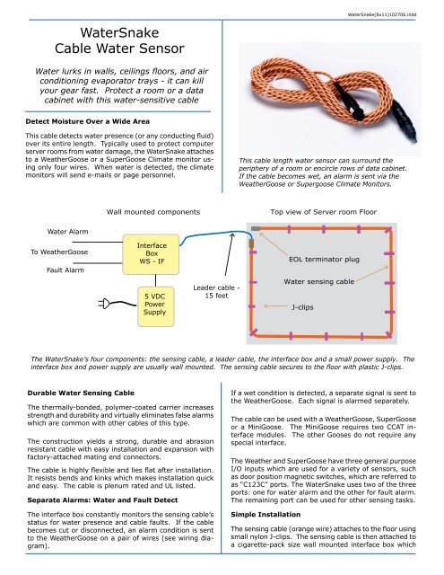
Wall mounted components<br />
Top view of Server room Floor<br />
<strong>Water</strong> Alarm<br />
To WeatherGoose<br />
Fault Alarm<br />
Interface<br />
Box<br />
WS - IF<br />
5 VDC<br />
Power<br />
Supply<br />
Leader cable -<br />
15 feet<br />
EOL terminator plug<br />
<strong>Water</strong> sensing cable<br />
J-clips<br />
The <strong><strong>Water</strong>Snake</strong>’s four components: the sensing cable, a leader cable, the interface box and a small power supply. The<br />
interface box and power supply are usually wall mounted. The sensing cable secures to the floor with plastic J-clips.<br />
Durable <strong>Water</strong> Sensing <strong>Cable</strong><br />
The thermally-bonded, polymer-coated carrier increases<br />
strength and durability and virtually eliminates false alarms<br />
which are common with other cables of this type.<br />
The construction yields a strong, durable and abrasion<br />
resistant cable with easy installation and expansion with<br />
factory-attached mating end connectors.<br />
The cable is highly flexible and lies flat after installation.<br />
It resists bends and kinks which makes installation quick<br />
and easy. The cable is plenum rated and UL listed.<br />
Separate Alarms: <strong>Water</strong> and Fault Detect<br />
The interface box constantly monitors the sensing cable’s<br />
status for water presence and cable faults. If the cable<br />
becomes cut or disconnected, an alarm condition is sent<br />
to the WeatherGoose on a pair of wires (see wiring diagram).<br />
If a wet condition is detected, a separate signal is sent to<br />
the WeatherGoose. Each signal is alarmed separately.<br />
The cable can be used with a WeatherGoose, SuperGoose<br />
or a MiniGoose. The MiniGoose requires two CCAT interface<br />
modules. The other Gooses do not require any<br />
special interface.<br />
The Weather and SuperGoose have three general purpose<br />
I/O inputs which are used for a variety of sensors, such<br />
as door position magnetic switches, which are referred to<br />
as “C123C” ports. The <strong><strong>Water</strong>Snake</strong> uses two of the three<br />
ports: one for water alarm and the other for fault alarm.<br />
The remaining port can be used for other sensing tasks.<br />
Simple Installation<br />
The sensing cable (orange wire) attaches to the floor using<br />
small nylon J-clips. The sensing cable is then attached to<br />
a cigarette-pack size wall mounted interface box which
converts the cables’s signal into voltage levels suitable for<br />
the WeatherGoose’ I/O inputs. A small wall transformer<br />
supplies power.<br />
Variety of Sensing <strong>Cable</strong> Lengths<br />
The water-sensing cable can be ordered in a variety of<br />
lengths. Note that the sensing cable must have the EOL<br />
(End of Line) cable terminator at the end of the run. The<br />
intermediate cables do not require the EOL connector. Up<br />
to 100 feet of sensing cable can be used.<br />
If the cable needs to cross areas where water sensing is<br />
not needed, a non-sensing intermediary cable can be used.<br />
Both types of cables ship with pre-installed connectors.<br />
Failsafe Supervisiory Alarm Mode<br />
- Fail Safe Alarms<br />
Interface Box - Outputs WeatherGoose<br />
Black: <strong>Water</strong> Detect (-)<br />
Constant current flow<br />
Red: <strong>Water</strong> Detect (+)<br />
Green: Fault Alarm (+)<br />
Constant current flow<br />
C 1 2 3 C<br />
Installation of the cable should be on non-conducting surfaces<br />
such as vinyl tile or concrete.<br />
Sensing <strong>Cable</strong> Technical Specifications<br />
Plenum Rating: CL2P/CMP C(UL)<br />
Sheer Strength: >180 lbs. (>81.65kg)<br />
Cut Through Resistance: >40 lbs. (>18.14kg) with .005”<br />
(0.127mm) blade<br />
Abrasion Resistance: 60 cycles per UL 719<br />
Connector: 4 pin, 0.96” (24.38mm) diameter<br />
Operating Environment<br />
Temperature: 32° to 167°F (0° to 75°C)<br />
Humidity: 5% to 95% RH, non-condensing<br />
Altitude: 10,000’ (3,048m) max.<br />
Storage: -22° to 185°F (-30° to 85°C)<br />
White: Fault Alarm (- )<br />
When the <strong><strong>Water</strong>Snake</strong> is configured in the Supervisory<br />
Mode, as shown above, the relays are in a constant<br />
closed state. If the power should fail or the cable<br />
become disconnected, an alarm will be sent.<br />
Wall-Mounted Interface Box<br />
Dimensions<br />
SC-10 10’ (3.05m)<br />
SC-25 25’ (7.62m)<br />
SC-50 50’ (15.24m)<br />
SC-100 100’ (30.48m)<br />
Diameter of cable: not more than 0.25” (6.35mm).<br />
Custom lengths (available upon request)<br />
Weight .02 lbs/ft (29.74g/m)<br />
Certifications UL STD E162948<br />
Installation & Setup<br />
No special tools are required. Only a screwdriver and wire<br />
cutter are required for installation.<br />
Controls inside Interface Box<br />
1. High/Low Switch: (JP1)<br />
To set the sensitivity, move the jumper to the desired<br />
sensitivity position. Low means that a leak will be reported<br />
when a large amount of water is present. High means that<br />
a leak will be reported when a small amount of water is<br />
present.<br />
The cigarette pack size box mounts on the wall and<br />
connects to the sensing cable and the WeatherGoose.<br />
An “on” green light indicates no faults. If the light is<br />
flashing, either water or a cable fault has been detected.<br />
The wires are attached using screw terminals.<br />
2. SUP/NON (Supervised or Non Supervised Relay Configuration)<br />
selector jumper (JP2)
This jumper configures the output relay(s) as supervised<br />
or non-supervised.<br />
If the relays are supervised, the relays will remain “On<br />
(Closed)” until either power goes away or an alarm is detected<br />
(Relay will turn “Off”).<br />
If the relays are non-supervised (normal state is “Off<br />
(Open)”), then when an alarm is detected the relays will<br />
activate (“On Closed)”).<br />
Indicator Light: steady green means normal operation,<br />
no faults detected. Flashing green means water detected<br />
or cable fault detected. No green light indicates no power<br />
to unit.<br />
Wiring Connection:<br />
1. Connect the <strong>Water</strong> Leak Detection <strong>Cable</strong> to control<br />
panel’s leader cable.<br />
The EOL connector must be connected at the end<br />
of the sensing cable.<br />
2. Prior to J-clip attachment, prepare the floor surface -<br />
clean with denatured alcohol.<br />
3. Unroll the wire; do not allow kinks to develop in the wire.<br />
Lay the cable per installation drawings. Mark the drawings<br />
with any variances.<br />
4. Place J-clips every 3’ to 4’(0.9m to 1.2m) plus one at<br />
each turn in the cable.<br />
J-clips secure the cable to the floor. Use<br />
denatured alcohol to remove any grease on the<br />
floor before applying the clips. Place J-clips<br />
every 3 or 4 feet, and on each corner.<br />
5. Avoid placing the cable directly under or in front of an<br />
air-conditioning unit. If you must place the cable in front of<br />
a down-flow air conditioner, the cable should be placed at<br />
least 6’ away. Use one J-clip every 12” - 18” (0.3m -0.45m)<br />
to keep the cable firmly affixed to the floor.<br />
<strong><strong>Water</strong>Snake</strong> Components<br />
Item Purpose Part No. Quan. Req.<br />
Required Components: everything needed except water detection cable and J-clips<br />
1. Interface Box Interfaces detection cable to Weather Goose WS-IF 5” x 1” x 6” One<br />
2. Leader <strong>Cable</strong> Connects sensing cable to Interface Box WS-LC-15 15’ One<br />
3. Power Supply 5VDC, included with WS-IF Unit WA-DC-5 6’ cord One<br />
4. Four pair cable Connects WS-IF to WeatherGoose NSC-B-50 50’ cord One<br />
Sensing <strong>Cable</strong> and J-Clips<br />
Leak Detection <strong>Cable</strong> (w/ EOL (End of Line) terminator installed) SC-10-EOL 10’ One of<br />
Note: one cable must have an EOL terminator SC-14-EOL 40’ either type<br />
Leak Detection <strong>Cable</strong> (extenders, with no EOL terminators) SC-10 10’ Optional<br />
As required up to 110” SC-25 25’ “<br />
SC-50 50’ “<br />
SC-100 100’ “<br />
Non-Sensing <strong>Cable</strong><br />
Extends sensing wire through non-monitored areas.<br />
NSC-10 10’ Optional<br />
NSC-25 25’ “<br />
NSC-50 50’ “<br />
NSC-100 100’ “<br />
J-Clips One clip every 3 to 4 feet of sensing wire JC-10 Quan. 10 One per foot<br />
Plus one for each corner JC-25 Quan. 20 “
6. When running cable over obstructing objects, affix<br />
one J-clip on either side of the object, as close as possible<br />
to the object.<br />
Setting the Sensitivity (JP1)<br />
There are two jumpers inside the control box, both located<br />
towards the upper-right side of the circuit board,<br />
marked JP1 and JP2. These jumpers should be set as<br />
follows:<br />
JP1 controls the sensitivity to water along the detection<br />
cable. A LOW reduces the unit’s sensitivity, requiring a<br />
relatively larger amount of water to set off the alarm.<br />
Conversely, the “HIGH” setting will increase the sensitivity<br />
and allow a relatively small amount of water to trip<br />
the alarm. For most indoor server-room applications,<br />
the “HIGH” setting is recommended, but you may wish<br />
to experiment with this setting to see which sensitivity<br />
level best suits your particular installation.<br />
Setting the Relay Alarm Mode Jumper (JP2) Non<br />
Supervised Mode<br />
JP3 controls the action of the relays.<br />
In “SUP”ervised mode, the relays will switch ON (i.e., the<br />
normally-open contact pair will be closed) when power<br />
is applied to the unit, and will switch OFF if an alarm<br />
condition occurs or if power is removed from the unit.<br />
In the “NON”-supervised mode, the relays remain off<br />
until an alarm condition occurs. Either mode will work<br />
with the WxGoos, although the “SUP” mode does provide<br />
the additional advantage of allowing you to detect<br />
a power failure at the control box.<br />
The Supervised Alarm Mode is recommended because<br />
the WeatherGoose will receive an alarm if the cable is<br />
broken or the <strong><strong>Water</strong>Snake</strong> power fails.<br />
Setting the Alarm Thresholds in Supervised Mode<br />
(Recommended)<br />
Once you have connected the relay wires to the WxGoos<br />
I/O ports as shown in the diagram, setting up the alarms<br />
is straightforward:<br />
If you have set JP3 to “SUP”ervised mode, then the<br />
reading at the water-detection and cable-fault inputs will<br />
both be at (or close to) 00 when conditions are normal<br />
(i.e. when both relays are ON), and will rise to 99 (or<br />
close to it) if an alarm condition occurs and causes its<br />
associated relay to turn OFF.<br />
In this configuration, set the Low Trip of both I/O channels<br />
to -10 (disabling it, since the input reading cannot<br />
go below 00), and the High Trip to 60, insuring that the<br />
WxGoos alarm will trip when the relay opens.<br />
Setting the Alarm Thresholds in Non Supervised<br />
Mode<br />
If you have set JP3 to “NON”-supervised mode, then the<br />
relay action will be exactly the opposite of that described<br />
above.<br />
In this configuration, the Low Trip of both I/O channels<br />
should be set to 40 and the High Trip to 110; this will disable<br />
the High-Trip alarm (since the input reading can never<br />
go above 99) and insure that the Low-Trip alarm will go off<br />
when one of the relays closes.<br />
As mentioned previously, “SUP”ervised mode also allows<br />
you to see if the <strong>Water</strong>snake control unit has lost power. If<br />
this occurs, both relays will open, and both of their associated<br />
I/O channels on the WxGoos will rise to 99, causing<br />
SUPERVISOR MODE (LOW TRIP = -10, HIGH TRIP = 60)<br />
LEAK<br />
RELAY<br />
FAULT<br />
RELAY<br />
ALARM STATUS<br />
OFF OFF POWER FAILURE<br />
OFF ON WATER DETECTED<br />
ON OFF CABLE FAULT<br />
ON ON NORMAL OPERATION<br />
NON-SUPERVISOR MODE (LOW TRIP = 40, HIGH TRIP =<br />
110)<br />
LEAK<br />
RELAY<br />
FAULT<br />
RELAY<br />
ALARM STATUS<br />
OFF OFF NORMAL OPERATION<br />
OFF ON CABLE FAULT<br />
ON OFF WATER DETECTED<br />
ON ON POWER FAILURE<br />
both alarms to trip.<br />
Since the “water detected” and “cable fault” alert conditions<br />
are normally mutually exclusive (i.e. the unit cannot have<br />
detected water along the cable if there’s a cable fault, and<br />
vice-versa), receiving both alerts simultaneously can be<br />
taken as an indication that power to the <strong>Water</strong>snake unit<br />
has failed.<br />
Testing the <strong>Sensor</strong>s<br />
Test the sensing cable immediately after installation and every<br />
three months by wetting the cable with a wet towel.<br />
The alarm should respond in ten seconds, plus any Internet<br />
signal delays. Verify that the e-mail or page arrives at the<br />
proper address. When the sensing cable dries, the alarm<br />
state should clear.
<strong><strong>Water</strong>Snake</strong> Control Box Wiring (Supervisiory Mode shown)<br />
SENSITIVITY<br />
LOW HIGH<br />
JP1<br />
NON SUP<br />
JP2<br />
RELAY CONF<br />
Alarm relays can be set in<br />
two modes, Supervisiory or<br />
Non- Supervisiory. See text<br />
for more information on<br />
these modes<br />
5VDC IN<br />
- +<br />
FAULT<br />
LEAK<br />
NC C NO NC C NO<br />
<strong>Cable</strong> Input<br />
from Sensing<br />
<strong>Cable</strong> (Orange)<br />
GND<br />
+5V<br />
Red (Leak Hot)<br />
Black (Leak Common)<br />
Green (FAULT Hot)<br />
White (FAULT Common)<br />
+5V ISOLATED<br />
POWER SUPPLY<br />
“C” is common<br />
C<br />
1 2 3<br />
C<br />
WeatherGoose or SuperGoose I/O ports<br />
12885 Research Blvd. Suite 210B<br />
Austin, Texas 78750<br />
512-257-1462<br />
http://itwatchdogs.com