Joseph Drive Line#2 - Joseph Industries, Inc.
Joseph Drive Line#2 - Joseph Industries, Inc.
Joseph Drive Line#2 - Joseph Industries, Inc.

Create successful ePaper yourself
Turn your PDF publications into a flip-book with our unique Google optimized e-Paper software.
Vol.1, No.2<br />
Atechnical publication from <strong>Joseph</strong> <strong>Industries</strong>,<br />
the specialist in drive line<br />
replacement components<br />
for the industrial/construction<br />
equipment markets.<br />
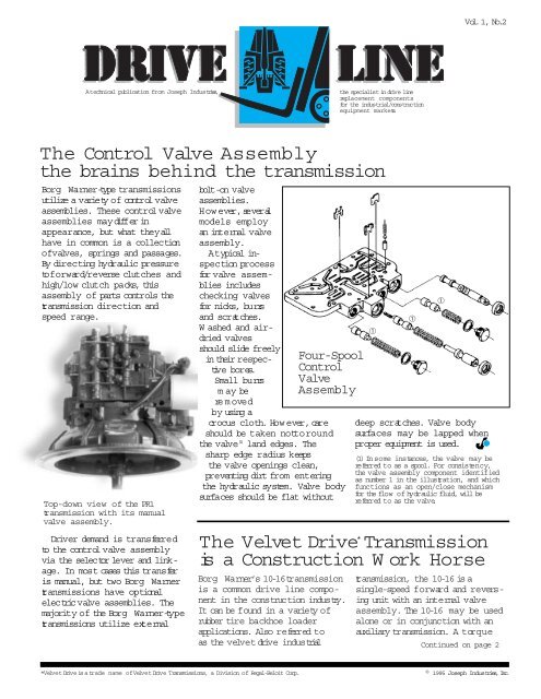
The Control Valve Assembly<br />
the brains behind the transmission<br />
Borg Warner-type transmissions<br />
utilize a variety of control valve<br />
assemblies. These control valve<br />
assemblies may differ in<br />
appearance, but what they all<br />
have in common is a collection<br />
ofvalves, springs and passages.<br />
By directing hydraulic pressure<br />
toforward/reverse clutches and<br />
high/low clutch packs, this<br />
assembly of parts controls the<br />
transmission direction and<br />
speed range.<br />
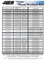
Top-down view of the PR1<br />
transmission with its manual<br />
valve assembly.<br />
<strong>Drive</strong>r demand is transferre d<br />
to the control valve assembly<br />
via the selector lever and linkage.<br />
In most cases this transfer<br />
is manual, but two Borg Warner<br />
transmissions have optional<br />
electricvalve assemblies. The<br />
majority of the Borg Warner-type<br />
transmissions utilize external<br />
bolt-on valve<br />
assemblies.<br />
However,several<br />
models employ<br />
an internal valve<br />
assembly.<br />
Atypical inspection<br />
process<br />
for valve assemblies<br />
includes<br />
checking valves<br />
for nicks, burrs<br />
and scratches.<br />
W ashed and airdried<br />
valves<br />
should slide freely<br />
in their respective<br />
bores.<br />
Small burrs<br />
m ay be<br />
removed<br />
by using a<br />
crocus cloth. How ever, care<br />
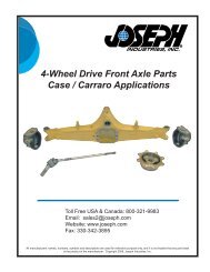
Four-Spool<br />
Control<br />
Valve<br />
Assembly<br />
should be taken nottoround<br />
the valve (1) land edges. The<br />
sharp edge radius keeps<br />
the valve openings clean,<br />
preventing dirt from entering<br />
the hydraulic system. Valve body<br />
surfaces should be flat without<br />
deep scratches. Valve body<br />
surfaces may be lapped when<br />
proper equipment is used.<br />
(1) In s ome ins tances, the valve may be<br />
referred to as a spool. For consistency,<br />
the valve assembly component identified<br />
as number 1 in the illustration, and which<br />
functions as an open/close mechanism<br />
for the flow of hydraulic fluid, will be<br />
referred to as the valve.<br />
The Velvet <strong>Drive</strong> * Transmission<br />
is a Construction W ork Horse<br />
Borg Warner’s 10-16transmission<br />
is a common drive line component<br />
in the construc tion industry.<br />
It can be found in a variety of<br />
rubber tire backhoe loader<br />
applications. Also referred to<br />
as the velvet drive industrial<br />
➀<br />
➀<br />
transmission, the 10-16 is a<br />
single-speed forward and reversing<br />
unit with an internal valve<br />
assembly. The 10-16 may be used<br />
alone or in conjunction with an<br />
auxiliary transmission. A torque<br />
➀<br />
Continued on page 2<br />
*Velvet <strong>Drive</strong> isatrade name ofVelvet <strong>Drive</strong> Transmissions, a Division of Regal-Beloit Corp.<br />
© 1995 <strong>Joseph</strong> <strong>Industries</strong>,<strong>Inc</strong>.
The Velvet <strong>Drive</strong> Transmission<br />
is a Construction W ork Horse Continued from page 1<br />
converter between engine<br />
and transmission permits<br />
stopping the vehicle in gear<br />
with the engine running. The<br />
10-16transmission consists of<br />
a planetary gear set, a multipledisc<br />
reverse clutch and a<br />
multiple-disc forward clutch.<br />
The input and output shafts<br />
are coaxial. Hydraulic pressure<br />
is supplied by a gear-type oil<br />
pump driven at engine speed<br />
by the torque converter hub.<br />
Oilfrom the pump is directed<br />
to the pressure regulator and<br />
control valves. Converter<br />
pressure is maintained by a<br />
converterregulator valve. The<br />
regulator valve within the valve<br />
assembly controls oil pressure<br />
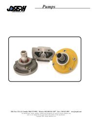
10-1 6 Valve Assembly<br />
VALVE<br />
SEAL RING<br />
PLUNGER<br />
SPRING<br />
PIN<br />
“O”RING<br />
SELECTOR<br />
VALVE<br />
SPRING<br />
10-1 6 Velvet <strong>Drive</strong> Transmission<br />
CONVERTER<br />
RELIEF VALVE<br />
NEUTRAL<br />
SWITCH<br />
DIPSTICK<br />
(OR FILLER TUBE)<br />
BYPASS HOSE<br />
OUTLET TO OIL<br />
COOLER<br />
COOLER<br />
RETURN HOSE<br />
ID TAG<br />
MODEL NO.<br />
SERIAL NO.<br />
BREATHER<br />
REVERSE CLUTCH<br />
PRESSURE<br />
RETURN FROM<br />
OIL COOLER<br />
ELECTRIC<br />
SOLENOID<br />
SPRING<br />
SPRING<br />
RETAINER<br />
REGULATOR<br />
VALVE<br />
PIN<br />
SNAP RING<br />
EXPANSION PLUG<br />
levelfor the entire unit.Oil<br />
is direc ted to journals and<br />
bushings through transmission<br />
case passages to supply<br />
pressure lubrication. Oil discharged<br />
from the pressure<br />
regulator and converterrelief<br />
valve is direc ted back to the<br />
transmission sump.<br />
M oving the forward and<br />
reverse shift lever causes oil to<br />
be directed to the appropriate<br />
clutch forforward or reverse<br />
DRAIN<br />
PLUG<br />
operation. Selecting<br />
neutral directs oil back into<br />
the sump, disengaging the<br />
clutch packs.<br />
2
Pumping life<br />
into the transmission<br />
If the control valve assembly<br />
is the brains behind the transmission,<br />
then the pump is<br />
the heart of the tr ansmission.<br />
Before the transmission can<br />
do anything it must have<br />
hydraulic pressure. And this<br />
pressure is generated by<br />
the pump.<br />
The pump housing<br />
is mounted to the<br />
transmission with<br />
its drive gear<br />
connected to the<br />
torque converter<br />
hub. This means<br />
that any time the<br />
engine is running,<br />
w h ether the<br />
transmission is<br />
in gear or not,the<br />
pump’s drive gear<br />
isrotating.<br />
The sole purpose<br />
of the pump is to<br />
deliver more oil than the<br />
transmission requires, whether<br />
at idle or at high rpm speeds.<br />
Hydraulic oil enters the pump<br />
through the intake screen and<br />
transmission case passages.<br />
Oil leaving the pump is directed<br />
through case and adapter<br />
passages to the pressure<br />
regulator valve, the open<br />
valve body passages and the<br />
torque converter.<br />
Common Borg Warner-type<br />
automatic transmissions<br />
The pump is designed to<br />
have more capacity than the<br />
transmission requires. It is the<br />
pressure regulator valve’s job to<br />
handle the excess oil pressure.<br />
After oil has f illed all open<br />
circuits, line pressure increases,<br />
building on the end of the<br />
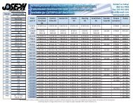
Major P u mp Components<br />
Converter<br />
Support<br />
<strong>Drive</strong><br />
Gear<br />
Housing<br />
<strong>Drive</strong>n<br />
Gear<br />
pressure regulator valve.<br />
The pressure buildup reaches<br />
a point where it overcomes<br />
an opposing spring force,<br />
opening the regulator valve.<br />
The opening draws mainline<br />
oil back into the sump. This<br />
low ers the pressure until it is<br />
balanced against the opposing<br />
spring force. At this point<br />
the oil line pressure is<br />
regulated.<br />
Old<br />
Designation<br />
New *<br />
Designation Type Typical Applications<br />
T11 10-11 2-speed lift trucks<br />
T12 10-01 1-speed lifttruck,utility<br />
construc tion vehicles<br />
T17 10-10 1-speed lift trucks<br />
T22 10-08 1-&<br />
2-speeds<br />
lift trucks, locomotives<br />
T27 10-12 2-speed lift trucks<br />
T72 10-16 1 speed backhoe tractors<br />
PR1 10-21 1-speed lifttrucks,utility<br />
construc tion vehicles<br />
PR2 10-22 2-speed lift trucks<br />
*This designation changes once the original equipment manufacturer<br />
assigns its own OEM part number to the Borg Warner transmission.<br />
<strong>Drive</strong> Line<br />
talks back<br />
This feature is your opportunity<br />
to present the experts at <strong>Joseph</strong><br />
<strong>Industries</strong> with your drive line<br />
component questions. Send<br />
your questions and comments to<br />
<strong>Drive</strong> Line, c/o <strong>Joseph</strong> <strong>Industries</strong>,<br />
10039 Aurora-Hudson Rd., Streetsboro,<br />
Ohio 44241.<br />
H ow is reliability assured<br />
with <strong>Joseph</strong> <strong>Industries</strong>’<br />
rebuilt transmissions<br />
As standard practice, all <strong>Joseph</strong><br />
and Concorarebuilt transmissions<br />
have new bearings, gaskets, rubber<br />
lip seals, sealing rings, clutch plates<br />
and pump. All gears, drums and<br />
brakes are inspected for wear.<br />
All components showing visible<br />
signs of wear are replaced. Before<br />
each transmission is shipped,<br />
hydraulic pressure istested at two<br />
rpm levels ensuring the unit meets<br />
all pressure levels specified in<br />
the O.E.M.’s service manual.<br />
H ow does the transmission<br />
core policy work<br />
Every tr ansmission sent to <strong>Joseph</strong><br />
<strong>Industries</strong>forrebuilding is issued<br />
a core refund. Subtracted from this<br />
refund is the replacement costof<br />
w orn components not part of the<br />
rebuild kit.P arts replaced as standard<br />
practice in rebuilding a transmission<br />
include bearings, gaskets,<br />
rubber lip seals, sealing rings,<br />
clutch plates and the pump.<br />
Can you o fer some tips for<br />
rebuilding a transmission<br />
1. Be thorough.<br />
2. Clean every part before<br />
reassembly. Dirt in the system<br />
can accelerate component wear.<br />
3. Check everything, replacing all<br />
w orn parts. Remember, wear<br />
causes pressure losses.<br />
4. Check all clearances, making<br />
sure they meet the manufacturer’s<br />
specifications outlined in the<br />
service manual.<br />
3