Download the Complete Kit Notes - Mini-Kits
Download the Complete Kit Notes - Mini-Kits
Download the Complete Kit Notes - Mini-Kits

Create successful ePaper yourself
Turn your PDF publications into a flip-book with our unique Google optimized e-Paper software.
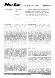
<strong>Mini</strong>-kits ®<br />
AD9850/51 DDS Experimenters <strong>Kit</strong> EME85F VERSION2.<br />
SPECIFICATIONS: Frequency Range 0Hz – 60MHz ( AD9851 )<br />
Frequency Resolution<br />
1Hz steps RF & Display Readout<br />
Frequency Steps 1Hz Low Rate ( Variable Rate Tuning )<br />
Software dd_synth_ver2.1 ( Email <strong>Mini</strong>-<strong>Kit</strong>s for Software )<br />
Output Low pass Filter<br />
RF Output<br />
0 to 30MHz or 0 to 70MHz Elliptic<br />
+7dBm, ( 5mW minimum ), typically +9dBm<br />
Power +12 to 13.8 volts ( 140mA excluding LCD Display )<br />
DESCRIPTION: If you are building any of <strong>the</strong> DDS VFO <strong>Kit</strong>s or SWEEP <strong>Kit</strong> <strong>the</strong>n please refer to <strong>the</strong> additional notes<br />
for <strong>the</strong>se <strong>Kit</strong>s before reading this document. This document refers to <strong>the</strong> basic EME85 DDS <strong>Kit</strong> that uses <strong>the</strong> older version<br />
dd_synth_ver2.1 software & Basic Version 1 control circuit.<br />
The <strong>Kit</strong> uses a preprogrammed PIC16F628 Micro controller to control a AD9850/51 DDS & a standard Hitachi 2 Line x 16<br />
character LCD display module. The Software can be easily changed to allow <strong>the</strong> DDS to be used for many applications. The<br />
<strong>Kit</strong> is supplied with <strong>the</strong> AD9851 as it is only a few dollars more compared to <strong>the</strong> AD9850, which are both are pin compatible.<br />
The EME85F PC board is now <strong>the</strong> 6th generation that allows experimentation with <strong>the</strong> AD9850/51 DDS chips. The previous<br />
update EME85E has extra plated through holes & filtering capacitors to reduce DDS noise on <strong>the</strong> 5 volt power supply rail.<br />
The EME85F has <strong>the</strong> addition of a solder mask, & a 2 pin socket for <strong>the</strong> power connection. The Pre-programmed software in<br />
<strong>the</strong> PIC allows <strong>the</strong> AD9851 DDS to tune from 1Hz to 60MHz which could be used as an accurate signal generator, or as a local<br />
oscillator for a receiver or transmitter. This <strong>Kit</strong> is essentially for experimenters that are prepared to experiment with <strong>the</strong> design<br />
& software to make a DDS for <strong>the</strong>ir own application.<br />
MICROCONTROLLER: The dd_synth_ver2.1 software allows <strong>the</strong> 16F628 to output data on pins 6, 11, & 13 to control <strong>the</strong><br />
AD9850/51 IC, along with driving a standard 16x2 LCD display, monitoring inputs from function buttons, & <strong>the</strong> rotary<br />
encoder. A combination of Switch inputs A to C are pulled low via external diodes to control Step size, RIT, Calibrate,<br />
Repeater mode, & RX to TX switching. Some errors can occur if two buttons are pressed at <strong>the</strong> same time. Encoder A & B<br />
inputs are for a standard mechanical rotary encoder like <strong>the</strong> ALPs EC12E for tuning & Step size. Outputs on pins 7 to 13 are<br />
used to drive a standard Hitachi 2 line x 16 character LCD display module. Many different brands of 16x2 displays should<br />
work ok with this software. The software even allows displays without a R/W ( Read/Write ) connection to be used. An<br />
external 4MHz Crystal is used for <strong>the</strong> timing functions of <strong>the</strong> 16F628 Micro controller. All options & settings can now be<br />
made in a Calibration menu setup screen, so no reprogramming of <strong>the</strong> PIC16F628 is required to change anything. When in<br />
Calibration mode, <strong>the</strong> LCD Display is used as a Menu settings screen to change <strong>the</strong> user settings. Settings like frequency min<br />
& max, display multiplier, offset frequencies, & DDS clock frequency etc, can be made in this Menu. An explanation on <strong>the</strong><br />
operation of <strong>the</strong> DDS functions is explained in <strong>the</strong> readme file that can be downloaded from <strong>the</strong> http://<br />
www.minikits.com.au/eme85.htm webpage. The file does not include <strong>the</strong> HEX & ASM PIC software which is only<br />
available by email.<br />
AD9850/51 DDS IC: The chip incorporates many features that are not used in this design. Refer to <strong>the</strong> manufacturers Data<br />
Sheet & Technical <strong>Notes</strong> for fur<strong>the</strong>r information. The chip can be loaded with serial or parallel data, serial is used in this <strong>Kit</strong><br />
design. RF output from <strong>the</strong> DDS on pin 21 is essentially very low level, so an MAR-6 amplifier is used after an Elliptical Low<br />
Pass Filter to bring <strong>the</strong> level up to around +7dBm ( 5mW ). A MAR-6 has been used due to its low frequency gain >20dB, &<br />
normally produces around +2dBm output with a bias of 16mA. The MAR6 has been biased at 30mA for more output & is well<br />
under <strong>the</strong> 50mA maximum rating producing up to +9dBm output. Pin12 on <strong>the</strong> DDS is normally 0 volts, & increasing <strong>the</strong><br />
© 2009 <strong>Mini</strong>-<strong>Kit</strong>s P.O Box 368 Enfield Plaza, South Australia, 5085 www.minikits.com.au
+5V<br />
XTAL<br />
MODULE<br />
+5V<br />
1nF<br />
OUTPUT<br />
LEVEL<br />
VCC<br />
GND<br />
OUT<br />
5K<br />
0.1uF<br />
10uF<br />
+<br />
_<br />
3K9<br />
1<br />
2<br />
3<br />
4<br />
5<br />
6<br />
7<br />
8<br />
W_CLK<br />
FQ_UD<br />
SERIAL<br />
LOAD<br />
28<br />
27<br />
26<br />
25<br />
24<br />
23<br />
22<br />
21<br />
9<br />
20<br />
10 19<br />
11 18<br />
12 17<br />
13 16<br />
14 15<br />
AD9850/51BRS<br />
7805T<br />
+ +<br />
_<br />
10uF 10nF 10nF<br />
_<br />
10uF<br />
C1 10pF C2 33pF<br />
L1 390nH L2 330nH<br />
10nF<br />
C4 180pF C3 150pF C5 180pF<br />
22R 51R<br />
30MHz L.P.F.<br />
Shown<br />
MAR6<br />
0.1uF<br />
100uH<br />
0.1uF<br />
270R<br />
10nF<br />
+12V<br />
DDS<br />
OUTPUT<br />
+7dBm<br />
CONTROL<br />
CONNECTOR<br />
SWITCH A<br />
SWITCH B<br />
SWITCH C<br />
ENCODER A<br />
ENCODER B<br />
GND<br />
+5V<br />
1K<br />
1K<br />
1K<br />
1K<br />
1K<br />
1<br />
RA2 RA1<br />
18<br />
2<br />
RA3 RA0<br />
17<br />
3<br />
RA4 OSC1<br />
16<br />
4<br />
MCLR OSC2<br />
15<br />
5<br />
VSS VDD<br />
14<br />
6<br />
RB0 RB7<br />
13<br />
7<br />
RB1 RB6<br />
12<br />
8<br />
RB2 RB5<br />
11<br />
9<br />
RB3 RB4<br />
10<br />
PIC16F628<br />
4MHz<br />
CRYSTAL 22pF<br />
0.1uF<br />
22pF<br />
1K<br />
LCD CONTRAST<br />
ADJUSTMENT<br />
DB7<br />
DB6<br />
DB5<br />
DB4<br />
RS<br />
E<br />
R/W<br />
GND<br />
+5V<br />
Vo<br />
LCD DISPLAY<br />
CONNECTOR<br />
AD9850/51 DDS<br />
VERSION2<br />
R/W & Vo CONNECTIONS<br />
MANY NOT BE REQUIRED<br />
REFER TO THE DATA SHEET<br />
FOR THE LCD MODULE USED<br />
_
AD9850/51 DDS EXPERIMENTERS KIT EME85F<br />
voltage on this pin via a trimpot connected to <strong>the</strong> +5v rail can be used to decrease <strong>the</strong> RF output level. Ei<strong>the</strong>r an external high<br />
stability frequency reference, or an onboard TTL crystal oscillator module can be used for <strong>the</strong> DDS frequency reference. The<br />
preprogrammed PIC supplied is set for a frequency reference of 180MHz using <strong>the</strong> internal x6 multiplier with a 30MHz TTL<br />
crystal oscillator module. The software can be changed to use o<strong>the</strong>r reference clock frequencies, & ei<strong>the</strong>r x1 or a x6 internal<br />
multiplier by changing it in <strong>the</strong> Calibration setup menu.<br />
CONSTRUCTION:<br />
1. If you are building any of <strong>the</strong> DDS VFO <strong>Kit</strong>s or Sweep <strong>Kit</strong> <strong>the</strong>n please refer to <strong>the</strong> additional notes for <strong>the</strong>se <strong>Kit</strong>s<br />
before construction of this <strong>Kit</strong>. The PCB supplied is a professional plated through hole board with solder mask, which<br />
makes construction much easier. Most components are mounted on <strong>the</strong> top ground plane side of <strong>the</strong> board, & only <strong>the</strong> 7805T<br />
regulator is mounted on <strong>the</strong> bottom side.<br />
2. Follow <strong>the</strong> PC Board overlay diagram and circuit carefully, by checking <strong>the</strong> components and placing <strong>the</strong>m onto <strong>the</strong> board.<br />
Mount all <strong>the</strong> SMD components first, followed by <strong>the</strong> larger components. To solder in <strong>the</strong> chip capacitors & resistors, a pair of<br />
tweezers are used to hold <strong>the</strong>m in place, soldering one side first <strong>the</strong>n <strong>the</strong> o<strong>the</strong>r side. When soldering in <strong>the</strong> MAR-6 amplifier,<br />
<strong>the</strong> device is simply soldered to <strong>the</strong> striplines. Grounding is provided through <strong>the</strong> plated holes underneath <strong>the</strong> MAR-6 earth<br />
leads. If you are not using <strong>the</strong> optional 30 or 70MHz low pass filter, <strong>the</strong>n simply bridge out <strong>the</strong> PC board tracks with wire.<br />
When mounting <strong>the</strong> 7805T regulator, its leads are bent to enable <strong>the</strong> body to sit against <strong>the</strong> bottom of <strong>the</strong> board. It is suggested<br />
that <strong>the</strong> metal tag is <strong>the</strong>n soldered to <strong>the</strong> ground plane on <strong>the</strong> bottom of <strong>the</strong> board for heat dissipation. Be careful when<br />
mounting <strong>the</strong> 7805T & make sure that you mount it under <strong>the</strong> board <strong>the</strong> correct way around. A mistake here could<br />
damage <strong>the</strong> chips including <strong>the</strong> AD9850/51.<br />
CONNECTIONS: Unless you are building <strong>the</strong> basic EME85 DDS <strong>Kit</strong>, <strong>the</strong>n you should refer to <strong>the</strong> DDS VFO notes, or<br />
<strong>the</strong> Sweep <strong>Kit</strong> notes before you start to solder in any header plugs or do any wiring. The connection notes below refer<br />
only for <strong>the</strong> Basic EME85 DDS <strong>Kit</strong>. The EME85F <strong>Kit</strong> includes <strong>the</strong> EME85 Conn <strong>Kit</strong> & consists of 2, 6 & 10 way Header<br />
plugs & sockets to suit <strong>the</strong> LCD & control connections on <strong>the</strong> EME85F board. Connections to <strong>the</strong> LCD display & rotary<br />
encoder can be made using standard ribbon cable to <strong>the</strong> connections on <strong>the</strong> board. If you have bought a LCD display module,<br />
<strong>the</strong>n <strong>the</strong> data sheet would have been supplied with it. Most LCD modules may have extra connections, R/W or Vo that are not<br />
required to make <strong>the</strong> display work. The Data sheets for <strong>the</strong> LCD module & Alps EC12E Rotary Encoder can be downloaded<br />
from www.minikits.com.au/data.html There are three pins on <strong>the</strong> EC12E, <strong>the</strong> center one is <strong>the</strong> ground connection, <strong>the</strong> o<strong>the</strong>r<br />
two are A & B output. It is easy enough to experiment here with <strong>the</strong> A & B connections until you get it to change frequency in<br />
<strong>the</strong> right direction. For <strong>the</strong> RF output connection ei<strong>the</strong>r use 50 ohm cable directly wired to <strong>the</strong> board, or a small SMA09 PCB<br />
mount RF connector.<br />
CONTROL BOARD: The DDS V2.10 software is programmed to recognize two types of control boards when connected to<br />
<strong>the</strong> EME85 board. There is a basic control circuit Version 1 that has <strong>the</strong> basic functions, & a more advanced control circuit<br />
Version 2 that has an extra memory function & a spare switch for future expansion. Both circuits are available for download<br />
on <strong>the</strong> DDS WEB page www.minikits.com.au/eme85.htm The simple control board circuit Version 1 can be constructed by<br />
soldering diodes to momentary pushbutton switches mounted on a panel or box. The Optional Advanced EME129 Control<br />
board <strong>Kit</strong> Version 2 is no longer available August 2009 as an option, refer to <strong>the</strong> <strong>Mini</strong>-<strong>Kit</strong>s WEB site. The advanced<br />
control board Version 2 is too difficult to construct on Vero board without making mistakes, so it is recommended that you<br />
purchase <strong>the</strong> newer hardware & software PIC using <strong>the</strong> Version 3 control board EME159 <strong>Kit</strong>, 4x4 Keypad, & dd_synth<br />
_ver2.2 software.<br />
TESTING: Before applying any power to <strong>the</strong> DDS board, make sure that you have inserted <strong>the</strong> 7805T regulator in <strong>the</strong><br />
PCB <strong>the</strong> correct way around. Always use a current regulated power supply when initially applying power to <strong>the</strong> board.<br />
1. Turn <strong>the</strong> 1k ohm LCD Contrast Trimpot fully clockwise, & apply power to <strong>the</strong> board. Check that <strong>the</strong> LCD display<br />
© 2009 <strong>Mini</strong>-<strong>Kit</strong>s P.O Box 368 Enfield Plaza, South Australia, 5085 www.minikits.com.au
AD9850/51 DDS EXPERIMENTERS KIT EME85F<br />
lights up & shows <strong>the</strong> software version number & <strong>the</strong>n <strong>the</strong> frequency. Some LCD modules don’t require this as <strong>the</strong>y have<br />
onboard bias resistors. If you still get no display <strong>the</strong>n check your wiring to <strong>the</strong> LCD display. Any wiring faults to <strong>the</strong><br />
control board will cause <strong>the</strong> LCD to show erratic numbers or possibly not work.<br />
2. To check for RF output from <strong>the</strong> DDS, tune a HF Receiver to 10.5MHz & set <strong>the</strong> DDS frequency to 10.5MHz & check for<br />
a carrier from <strong>the</strong> DDS. The 5kohm SMD trimpot will have to be adjusted to get an output from <strong>the</strong> DDS. 0 Volts on <strong>the</strong><br />
center wiper of <strong>the</strong> trimpot will produce maximum RF output. Be careful when measuring any voltages with a<br />
Multimeter around <strong>the</strong> DDS chip, as one slip could destroy <strong>the</strong> chip.<br />
ADDITIONAL NOTES:<br />
1. The DDS software is only available from <strong>Mini</strong>-<strong>Kit</strong>s by email. Also visit www.minikits.com.au/ki<strong>the</strong>lp.html for any <strong>Kit</strong><br />
changes or modifications.<br />
2. To go into Calibration Menu mode, hold <strong>the</strong> CAL switch down & apply power, +12 volts to <strong>the</strong> DDS board. The display<br />
should show ( ENABLE RPT NO ). Stop pressing <strong>the</strong> CAL button & press it again & again it will cycle through <strong>the</strong> options.<br />
The DDS x1 or x6 multiplier along with DDS reference frequency 180MHz can be set. For a 30MHz Xtal Module <strong>the</strong> DDS<br />
reference should be 180MHz, ( 30MHz x6 ). All options can be changed by pressing <strong>the</strong> Cal button & turning <strong>the</strong> rotary<br />
encoder. When you have set all <strong>the</strong> settings, ano<strong>the</strong>r press of <strong>the</strong> Cal button will save <strong>the</strong> settings to <strong>the</strong> eeprom in <strong>the</strong> PIC &<br />
return <strong>the</strong> display to normal. You will probably have to change <strong>the</strong> default 1Hz frequency step size to a higher tuning rate by<br />
pressing <strong>the</strong> step button, & turning <strong>the</strong> rotary encoder before changing <strong>the</strong> settings.<br />
3. The current Software Version 2.10 & later only supports <strong>the</strong> PIC16F628 chip only. There was not enough memory<br />
available to use a PIC16F84 chip for <strong>the</strong> extra functions, & memories.<br />
4. It is suggested that <strong>the</strong> DDS board be mounted inside a metal box as it radiates quite a lot of spurious RF possibly from <strong>the</strong><br />
Xtal module. Recently an interference problem on TV channel 9 VHF was tracked down to RF radiating from <strong>the</strong> DDS board.<br />
All leads in & out of <strong>the</strong> box should be kept as short as possible, & use ferrites over <strong>the</strong> leads if possible.<br />
5. The maximum recommended DDS output frequency for a 100MHz crystal oscillator, is 30MHz, which is a 3rd. Because of<br />
this <strong>the</strong> DDS will not be very clean above 30MHz, it will be a compromise. To use up to 60MHz <strong>the</strong> highest possible<br />
frequency output recommended for <strong>the</strong> AD9851, use a 30MHz crystal oscillator & <strong>the</strong> internal x6 Oscillator Multiplier. To<br />
produce an even cleaner output for local oscillators, it is suggested that <strong>the</strong> DDS output be filtered through a bandpass filter, or<br />
used with a 1:1 phase locked loop. The frequency display can be offset in <strong>the</strong> software to accommodate this. Optional 30 &<br />
70MHz Low Pass Filter <strong>Kit</strong>s are available to clean up <strong>the</strong> output of <strong>the</strong> DDS.<br />
6. Confirmation on whe<strong>the</strong>r <strong>the</strong> DDS board is working ok, can be made by disconnecting <strong>the</strong> LCD & control board<br />
connections & <strong>the</strong>n reapplying power to <strong>the</strong> DDS board. The PIC supplied with <strong>the</strong> <strong>Kit</strong> is pre-programmed for a default output<br />
frequency of 10.5MHz from <strong>the</strong> DDS chip that can be checked on a suitable HF receiver. This is only <strong>the</strong> case when using a<br />
30MHz module & <strong>the</strong> menu settings have not be changed.<br />
7. The DDS RF output can be seen on an oscilloscope as a very clean sine wave. It can also be seen on a Spectrum Analyzer<br />
or heard by tuning into <strong>the</strong> signal on a suitable HF receiver. When operating <strong>the</strong> DDS from 0 to approx 32 MHz with <strong>the</strong><br />
30MHz filter fitted, <strong>the</strong> second harmonic is only around 20dB down. This is due to <strong>the</strong> MAR6 acting as a multiplier. The<br />
drive to <strong>the</strong> MAR6 if reduced by adjusting <strong>the</strong> SMD trimpot will stop <strong>the</strong> multiplier action with reduced output level at <strong>the</strong><br />
fundamental frequency. This was not see as an issue as <strong>the</strong> DDS was designed as a simple signal generator only. If <strong>the</strong> DDS is<br />
to be used on a receiver or transmitter <strong>the</strong>n <strong>the</strong> MAR6 can be replaced with a high dynamic range amplifier stage, & narrow<br />
band local oscillator filtering for better performance.<br />
© 2009 <strong>Mini</strong>-<strong>Kit</strong>s P.O Box 368 Enfield Plaza, South Australia, 5085 www.minikits.com.au
AD9850/51 DDS EXPERIMENTERS KIT EME85F<br />
8. When using <strong>the</strong> DDS as a local oscillator for a receiver or transmitter, a simple 50ohm bandpass filter should be used on <strong>the</strong><br />
output of <strong>the</strong> DDS that covers <strong>the</strong> frequency range required to stop unwanted frequencies getting to <strong>the</strong> receiver or transmitters<br />
mixer. Without a filter <strong>the</strong> DDS used on a receiver, may produce an approximate 1Khz audio tone to be heard from <strong>the</strong><br />
receivers speaker. This is due to <strong>the</strong> DDS output being ra<strong>the</strong>r complex with <strong>the</strong> frequencies that are produced. A simple<br />
1MHz high pass filter on <strong>the</strong> output of <strong>the</strong> DDS board may fix <strong>the</strong> audio tone problem when using <strong>the</strong> DDS on a receiver, ( Not<br />
Tested ). Alternatively a PLL, ( phase locked loop ) circuit with VCO, ( voltage controlled oscillator ) could be used. Most<br />
modern Transceivers use a DDS as a reference oscillator on a PLL.<br />
PARTS LIST:<br />
RESISTORS<br />
1 x 22R 1206 SMD Resistor<br />
1 x 51R 1206 SMD Resistor<br />
1 x 270R 1/4 Watt Resistor<br />
5 x 1k 1/4 Watt Resistor<br />
1 x 3k9 1206 SMD Resistor<br />
TRIMPOTS<br />
1 x 1k TPV 5mm Trimpot Resistor<br />
1 x 5k SMD Trimpot Resistor<br />
CAPACITORS<br />
2 x 22pF Ceramic Capacitor<br />
1 x 1nF Ceramic Capacitor<br />
1 x 1nF 0805 Chip Capacitor<br />
3 x 10nF 0805 Chip Capacitor<br />
2 x 10nF Monolithic Capacitor<br />
4 x 0.1uF Monolithic Capacitor<br />
3 x 10uF EXR Electrolytic Capacitor 25v<br />
INDUCTORS, RF CHOKES<br />
1 x 100uH Axial RF Choke<br />
30MHz LPF OPTION<br />
1 x 10pF 0805 Chip Capacitor ( C1 )<br />
1 x 33pF 0805 Chip Capacitor ( C2 )<br />
1 x 150pF 0805 Chip Capacitor ( C3 )<br />
2 x 180pF 0805 Chip Capacitor ( C4 & 5 )<br />
1 x 330nH SMD Coil ( L2 )<br />
1 x 390nH SMD Coil ( L1 )<br />
70MHz LPF OPTION<br />
1 x 4p7 0805 Chip Capacitor ( C1 )<br />
1 x 10pF 0805 Chip Capacitor ( C2 )<br />
1 x 33pF 0805 Chip Capacitor ( C5 )<br />
1 x 39pF 0805 Chip Capacitor ( C4 )<br />
1 x 68pF Ceramic Capacitor ( C3 )<br />
1 x 150nH SMD Coil ( L2 )<br />
1 x 180nH SMD Coil ( L1 )<br />
SEMICONDUCTORS<br />
1 x 7805T Regulator<br />
1 x AD9851 DDS IC ( Soldered To PCB )<br />
1 x PIC16F628 Microprocessor ( Pre-programmed )<br />
1 x MAR-6 <strong>Mini</strong>-Circuits Amplifier<br />
( Bevel lead is <strong>the</strong> input )<br />
MISCELLANEOUS<br />
1 x PC Board EME85E<br />
1 x Instructions EME85E<br />
1 x 4MHz Microprocessor Crystal<br />
1 x 18 Pin IC Socket<br />
1 x HDS2P 2 Pin Socket<br />
1 x HDS6P 6 Pin Socket<br />
1 x HDS10P 10 Pin Socket<br />
1 x HDP2P 6 Pin PCB Mount Header<br />
1 x HDP6P 6 Pin PCB Mount Header<br />
1 x HDP10P 10 Pin PCB Mount Header<br />
OPTIONAL NOT INCLUDED IN KIT<br />
1 x Oscillator Module ( 30MHz standard )<br />
1 x Rotary Encoder ( EC16B ALPs )<br />
1 x 16 x 2 LCD Display Module<br />
1 x Software ( ddsv2.10, email sales@minikits.com.au<br />
for software )<br />
For any reported faults & modifications, please refer to www.minikits.com.au/ki<strong>the</strong>lp.html Refer to <strong>the</strong> EME85 DDS<br />
<strong>Kit</strong> links on this page for Help.<br />
© 2009 <strong>Mini</strong>-<strong>Kit</strong>s P.O Box 368 Enfield Plaza, South Australia, 5085 www.minikits.com.au
1<br />
2<br />
3<br />
4<br />
A<br />
CONTROL<br />
DDS BOARD<br />
SWITCH A<br />
SWITCH B<br />
SWITCH C<br />
ENCODER A<br />
ENCODER B<br />
GND<br />
KEYPAD<br />
R1<br />
R2<br />
R3<br />
1 2 3<br />
4 5 6<br />
7 8 9<br />
A<br />
B<br />
C<br />
R4<br />
* 0 #<br />
C1 C2 C3 C4<br />
D<br />
A = MEM<br />
B = CAL<br />
C = RIT<br />
D = RPT<br />
*<br />
= Step Size<br />
A<br />
A<br />
B<br />
ALL DIODES<br />
1N914, 1N4148<br />
OR SIMILAR<br />
B<br />
ROTARY<br />
ENCODER<br />
B<br />
16 x 2 LCD<br />
C<br />
GND<br />
TO LCD DISPLAY<br />
+12V<br />
DB7<br />
DB6<br />
DB5<br />
DB4<br />
RS<br />
E<br />
R/W<br />
GND<br />
+5V<br />
Vo<br />
TX<br />
DB7<br />
DB6<br />
DB5<br />
DB4<br />
RS<br />
E<br />
R/W<br />
GND<br />
+5V<br />
Vo<br />
C<br />
SDA<br />
(SWC)<br />
D<br />
+12V I/P<br />
SCL<br />
GND<br />
+12V<br />
GND<br />
D<br />
DD_Synth Ver 2.2x<br />
1<br />
2<br />
3<br />
4