
You also want an ePaper? Increase the reach of your titles
YUMPU automatically turns print PDFs into web optimized ePapers that Google loves.
THE <strong>RGB</strong> TO <strong>DVI</strong>(/<strong>VGA</strong>) CONVERTER THE <strong>RGB</strong> TO <strong>DVI</strong>(/<strong>VGA</strong>) CONVERTER THE <strong>RGB</strong> TO <strong>DVI</strong>(/<strong>VGA</strong>) CONVERTER<br />
1 Quick Setup<br />
This section briefly describes how <strong>to</strong> install your <strong>RGB</strong> <strong>to</strong> <strong>DVI</strong>(/<strong>VGA</strong>) <strong>Converter</strong> and<br />
optimize the video signals. Unless you are an experienced user, we recommend that you<br />
follow the full procedures described in the manual. The manual you can download on:<br />
http://www.ihse.de/pdf/b238-4f_e.pdf. Refer <strong>to</strong> the command summary on page 10<br />
when following this procedure.<br />
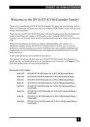
Install system<br />
1. Connect the <strong>RGB</strong> <strong>to</strong> <strong>DVI</strong>(/<strong>VGA</strong>) <strong>Converter</strong> <strong>to</strong> the <strong>RGB</strong> (video) source.<br />
2. Connect a display <strong>to</strong> the <strong>RGB</strong> <strong>to</strong> <strong>DVI</strong>(/<strong>VGA</strong>) <strong>Converter</strong>.<br />
3. Connect the <strong>DVI</strong>(/<strong>VGA</strong>) <strong>Converter</strong> <strong>to</strong> the Power supply<br />
4. Power up the system.<br />
Do you have a <strong>DVI</strong><br />
moni<strong>to</strong>r?<br />
Yes<br />
Is the <strong>RGB</strong> video-<br />
mode in the list of<br />
supported modes?<br />
(see page 46 in the<br />
manual)<br />
Carry out Setup of a new Video Mode procedure<br />
(please follow the instructions on page 38 in the<br />
manual).<br />
Done<br />
No<br />
No<br />
No<br />
Do you<br />
have a flat screen<br />
(TFT)?<br />
Carry out the Moni<strong>to</strong>r<br />
Setup procedure (please<br />
refer <strong>to</strong> its manual and see<br />
page 34 in the manual).<br />
Yes<br />
2 Installation<br />
For first-time users, we recommend that you carry out a test placement, confined <strong>to</strong> a<br />
single room, before commencing full installation. This will allow you <strong>to</strong> identify and<br />
solve any cabling problems, and experiment with the <strong>RGB</strong> <strong>to</strong> <strong>DVI</strong>(/<strong>VGA</strong>) <strong>Converter</strong><br />
more conveniently.<br />
2.1 Package Contents<br />
You should receive the following items in your <strong>RGB</strong> <strong>to</strong> <strong>DVI</strong>(/<strong>VGA</strong>) <strong>Converter</strong><br />
package:<br />
You should receive the following items in your <strong>RGB</strong> <strong>to</strong> <strong>DVI</strong>(/<strong>VGA</strong>) <strong>Converter</strong><br />
package:<br />
• <strong>RGB</strong> <strong>to</strong> <strong>DVI</strong>(/<strong>VGA</strong>) <strong>Converter</strong> unit.<br />
• <strong>RGB</strong>(S) <strong>to</strong> <strong>DVI</strong>-I cable<br />
• 6V DC 12W universal power supply for <strong>RGB</strong> <strong>to</strong> <strong>DVI</strong>(/<strong>VGA</strong>) <strong>Converter</strong>.<br />
• <strong>DVI</strong>-I <strong>to</strong> <strong>VGA</strong> adap<strong>to</strong>r (<strong>DVI</strong>-I dual link male <strong>to</strong> HD15 female) connec<strong>to</strong>r.<br />
• Data Cable DSUB9male- DSUB9female<br />
• Programming cable (DB9 female <strong>to</strong> RJ11 4p4c).<br />
• User manual (Quick Setup).<br />
• German-type power cord.<br />
• Infrared Remote Control (IR-RC)<br />
If anything is missing, please contact Technical Support.<br />
2.2 System Setup<br />
To install your <strong>RGB</strong> <strong>to</strong> <strong>DVI</strong>(/<strong>VGA</strong>) <strong>Converter</strong>:<br />
1. Switch off all devices.<br />
2. Connect your TFT directly <strong>to</strong> the device; connect a <strong>VGA</strong> screen by using the<br />
equipped <strong>DVI</strong>-I <strong>to</strong> <strong>VGA</strong> adapter.<br />
Attention: Connect the <strong>VGA</strong> moni<strong>to</strong>r cable <strong>to</strong> the adapter; then plug in<br />
the adapter in<strong>to</strong> the device. Otherwise, the <strong>VGA</strong> mode is not detected,<br />
<strong>DVI</strong> output is generated and there will be no picture on the screen (see<br />
also Diagnostic LEDs on page 1 in the manual).<br />
Under some circumstances, if your TFT supports both <strong>DVI</strong> and <strong>VGA</strong><br />
through a <strong>DVI</strong>-I cable, it might be necessary <strong>to</strong> use an additional <strong>DVI</strong>-I<br />
<strong>to</strong> <strong>DVI</strong>-D adap<strong>to</strong>r <strong>to</strong> get a <strong>DVI</strong> output. Please contact technical support<br />
for this accessory.<br />
3. <strong>RGB</strong>: Connect the graphic source <strong>to</strong> the input connec<strong>to</strong>rs using the equipped<br />
4xBNC-<strong>to</strong>-<strong>DVI</strong> adap<strong>to</strong>r. Please note, for connecting a CGA or EGA source,<br />
connect the optional CGA-<strong>to</strong>-<strong>DVI</strong> adap<strong>to</strong>r or EGA-<strong>to</strong>-<strong>DVI</strong> adap<strong>to</strong>r instead of the<br />
4x BNC-<strong>to</strong>-<strong>DVI</strong> adap<strong>to</strong>r.<br />
<strong>VGA</strong>: Connect the graphic source <strong>to</strong> the input connec<strong>to</strong>rs using the <strong>VGA</strong> <strong>to</strong><br />
<strong>DVI</strong>-I Cable which is an optional feature.<br />
EGA/CGA/MDA: Connect the graphic source <strong>to</strong> the input connec<strong>to</strong>rs as shown<br />
in , using the equipped Data Cable DSUB9male- DSUB9female.<br />
4. Connect the 6V power supply <strong>to</strong> power the unit.<br />
5. Turn on the system<br />
Only use the power supply originally supplied with<br />
this equipment or a manufacturer-approve<br />
replacement.<br />
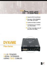
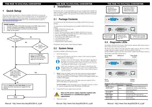
Connect <strong>to</strong><br />
EGA/CGA/MDA<br />
graphic source<br />
Connect <strong>to</strong> 6V<br />
Power supply<br />
Connect <strong>to</strong> the<br />
<strong>DVI</strong>/<strong>VGA</strong> Moni<strong>to</strong>r<br />
resp. TFT<br />
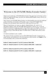
2.3 Diagnostic LEDs<br />
Each <strong>RGB</strong> <strong>to</strong> <strong>DVI</strong>(/<strong>VGA</strong>) <strong>Converter</strong> is fitted with four indica<strong>to</strong>r LEDs: Moni<strong>to</strong>r Detect,<br />
Device Ready and Video Signal and Power.<br />
The Moni<strong>to</strong>r Detect LED is <strong>to</strong> the right of the <strong>DVI</strong> output connec<strong>to</strong>r. The Power LED is<br />
<strong>to</strong> right of the power supply connec<strong>to</strong>r. The Device Ready is left <strong>to</strong> the<br />
EGA/CGA/MDA connec<strong>to</strong>r and Video Signal LEDs is right <strong>to</strong> the <strong>DVI</strong> Input connec<strong>to</strong>r.<br />
The location of the LEDs is shown below:<br />
Connect <strong>to</strong> <strong>RGB</strong> or<br />
<strong>VGA</strong> source (with<br />
<strong>RGB</strong> <strong>to</strong> <strong>DVI</strong>-cable)<br />
Device Ready IR-Receiver Video Signal<br />
(Red) (Green)<br />
Power Moni<strong>to</strong>r<br />
(Green) (Green)<br />
Programming connec<strong>to</strong>r<br />
– for firmware upgrades<br />
Diagnostic LEDs on <strong>RGB</strong> <strong>to</strong> <strong>DVI</strong>(/<strong>VGA</strong>) <strong>Converter</strong><br />
LED Appearance Diagnostics<br />
Moni<strong>to</strong>r Detect On<br />
Attached <strong>DVI</strong> moni<strong>to</strong>r (TFT) detected<br />
(Green LED) Flashing Attached <strong>VGA</strong> moni<strong>to</strong>r (CRT) detected<br />
Off<br />
No moni<strong>to</strong>r detected<br />
Device Ready On<br />
Device ready<br />
(Red LED) Off<br />
Device not ready<br />
Video Signal On<br />
Attached and valid mode detected<br />
(Green LED) Off<br />
No video signal or valid mode detected<br />
Power LED On<br />
Device ready<br />
(Green LED) Off<br />
Device not ready<br />
Manual : http://www.ihse.de/pdf/b238-4f_e.pdf Manual: http://www.ihse.de/pdf/b238-4f_e.pdf Manual : http://www.ihse.de/pdf/b238-4f_e.pdf
THE <strong>RGB</strong> TO <strong>DVI</strong>(/<strong>VGA</strong>) CONVERTER THE <strong>RGB</strong> TO <strong>DVI</strong>(/<strong>VGA</strong>) CONVERTER THE <strong>RGB</strong> TO <strong>DVI</strong>(/<strong>VGA</strong>) CONVERTER<br />
3 Device Control<br />
If you are using the CGA/EGA/MDA input or use an <strong>RGB</strong> format s<strong>to</strong>red in the internal<br />
table, no adjustment should be required. In other cases, you may need <strong>to</strong> optimize the<br />
output using the <strong>RGB</strong> <strong>to</strong> <strong>DVI</strong>(/<strong>VGA</strong>) <strong>Converter</strong>’s on-screen display (OSD).<br />
You can adjust the following properties using the IR-RC:<br />
• Brightness/contrast<br />
• Au<strong>to</strong> Configuration ON/OFF<br />
• Color, Color Temperatur adjustments<br />
• Brightness/contrast<br />
• Input Image Sizing<br />
• Output Image Scaling and Sizing<br />
• Video Mode selection for similar Video Modes (see Table on page 46)<br />
• OSD operation, fac<strong>to</strong>ry reset.<br />
3.1 Opening the OSD<br />
You can access the OSD in two ways:<br />
• Using the equipped Infrared Remote Control (IR-RC).<br />
• Using our WINDOWS program with a serial connection <strong>to</strong> the progr. port.<br />
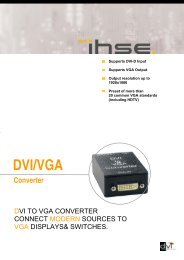
3.1.1 Using the IR-RC<br />
Version information<br />
Screen resolution and<br />
refresh rate of the<br />
video source<br />
Main menu icons<br />
Submenu/command<br />
icons<br />
Menu title<br />
exit OSD without saving values (ESC key)<br />
Navigate <strong>to</strong> the left, Parameter (-),(left arrow key)<br />
Navigate <strong>to</strong> the right, Parameter (+),(right arrow key)<br />
pop up theOSD, select function/ submenus, s<strong>to</strong>re<br />
modified parameter (Enter-Key)<br />
more contrast<br />
more brightness<br />
less brightness<br />
less contrast<br />
Reset <strong>to</strong> fac<strong>to</strong>ry settings (press twice!)<br />
Table os supported Video-Modes<br />
Bezeichnung Hres Vres V-freq Hz<br />
MONA S5 442 416 54,4<br />
AS 230 / 235 / OS 252 448 288 50,0<br />
GBE 3977 - 64x32 448 288 50,0<br />
DCC 555a 504 280 50,0<br />
WF 470 512 240 49,1<br />
WF 470 / AS 215 512 256 50,1<br />
WF 470 / AS 215 512 512 50,0<br />
WF 470 neu 512 245 50,1<br />
DCS 560 560 288 50,0<br />
DISET - 80x25 560 288 50,0<br />
GBE 3977 – 80x48 560 288 50,0<br />
GEM 80 graph i 560 224 50,0 / 60,0 / 75,0<br />
GEM 80 graph progr. 560 448 50,0 / 60,0 / 75,0<br />
MONA-C 560 413 58,2<br />
WF 480 580 480 60,0<br />
ABB MOD 300 640 385 60,0<br />
CGA 640 200 60,0<br />
COROS LS-C 640 405 59,1<br />
CP 526 highres. 50 Hz 640 468 50,0 / 60,0<br />
CP 528 highres. 60 Hz 640 468 60,0<br />
CP526/527 640 234 50,1<br />
DOS graphic Mode 640 350 70,0<br />
EGA (TTL) 640 350 59,9<br />
GEM 80 text 640 288 48,8<br />
IVE2 640 398 50,0<br />
IVE3 640 379 50,0<br />
IVE4 640 385 50,0<br />
MAC Mode 640 480 66,7<br />
OP 398 K 640 400 60,0<br />
Prokon 1 640 432 53,8<br />
Prokon 2 640 288 83,1<br />
Prokon 3 640 432 59,0<br />
Vesa Standard 640 350 85,0<br />
Vesa Standard 640 400 85,0<br />
Vesa Standard 640 480 60,0 / 72,8 / 75,0 / 85,0<br />
<strong>VGA</strong> 640 400 56,0 / 70,0<br />
WF 480 / Gracis 640 480 59,9<br />
NEC 642 200 60,0<br />
Std.- <strong>VGA</strong> 656 496 59,9<br />
NTSC (halfline) 680 240 60,0<br />
ABB DSAV110 720 336 50,0<br />
ABB DSAV111 720 336 61,2<br />
DOS Text Mode 720 400 70,0<br />
Hercules monochrom 720 350 49,8<br />
NTSC Interlaced 720 240 60,0<br />
NTSC progressive 720 480 60,0<br />
PAL Interlaced 720 288 50,0<br />
PAL progressive 720 576 50,0<br />
Teleperm / DS 078 720 408 60,0<br />
VDU 2000 Coros 720 405 59,1<br />
Vesa Standard 720 400 85,0<br />
PC-Textmode 738 414 70,1<br />
MTBI 746 246 60,0<br />
CP 527/ 60 800 468 59,9<br />
Vesa Standard 800 600 56,2 / 60,3 / 72,1 / 75,0 / 85,0<br />
MAC Mode 832 624 75,0<br />
Industrie Standard (I) 1024 768 87,0<br />
SUN Mode 1024 768 72,0<br />
Vesa Standard 1024 768 60,0 / 70,0 / 75,0 / 85,0<br />
DISET oversample 1120 288 50,0<br />
DMT1185 1152 864 70,0<br />
SUN Mode 1152 900 66,7<br />
Vesa Standard 1152 864 75,0<br />
GBE 3977 oversample 1164 288 50,0<br />
1280 interlaced 1280 512 40,0<br />
DMT127A 1280 960 75,0<br />
SUN Mode 1280 1024 66,7<br />
SXGA Unix 1280 1024 73,0<br />
TV Mode 1280 768 60,0<br />
TV Mode 1280 1024 50,1<br />
Vesa Standard 1280 960 60,0<br />
Vesa Standard 1280 1024 60,0 / 75,0<br />
<strong>RGB</strong> <strong>to</strong> <strong>DVI</strong>/<strong>VGA</strong><br />
<strong>Converter</strong><br />
<strong>Type</strong> <strong>K238</strong>-<strong>4F</strong><br />
(Quick Setup)<br />
Dear Cus<strong>to</strong>mer,<br />
before calling our Technical Support,<br />
please download the manual and check<br />
the Steps for Trouble Shooting on Page 40.<br />
If you still do not get a proper result,<br />
please download the check-list from:<br />
http://www.ihse.de/pdf/Timing_specs.pdf ,<br />
fill it out and fax it <strong>to</strong> us.<br />
Manual : http://www.ihse.de/pdf/b238-4f_e.pdf Manual: http://www.ihse.de/pdf/b238-4f_e.pdf Manual : http://www.ihse.de/pdf/b238-4f_e.pdf