DMFC stack.pdf - Electrochemical Engine Center
DMFC stack.pdf - Electrochemical Engine Center
DMFC stack.pdf - Electrochemical Engine Center

You also want an ePaper? Increase the reach of your titles
YUMPU automatically turns print PDFs into web optimized ePapers that Google loves.
1044<br />
G. Q. LU ET AL.<br />
0.6<br />
0.5<br />
Air breathing 8-cell <strong>DMFC</strong> <strong>stack</strong><br />
Anode 4.8 mg/cm 2 Pt/Ru<br />
Cathode 0.9 mg/cm 2 Pt, Nafion ® 112<br />
Single cell area: 5cm 2 ,<br />
2M methanol, ξ a =2@150mA/cm 2<br />
Room temperature<br />
Voltage (V)<br />
0.4<br />
20mA/cm 2<br />
50mA/cm 2<br />
0.3<br />
75mA/cm 2<br />
0.2<br />
1 2 3 4 5 6 7 8<br />
Cell number<br />
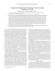
Figure 3. Voltage distribution after conditioning with the shielded cathode.<br />
3. RESULTS AND DISCUSSIONS<br />
MEA conditioning methods: Several methods were used to activate the catalysts in this 8-cell air<br />
breathing <strong>DMFC</strong> <strong>stack</strong>. Polarization curves were scanned from open circuit voltage to 0.1 V<br />
repeatedly for 2 h to condition the MEAs at room temperature. Following the voltage scan<br />
conditioning, cell performance was found to increase slightly. In another method, humidified<br />
hydrogen was used to condition the MEA for 2 h. After the conditioning, 2 M methanol solution<br />
was supplied to the cells to remove residual hydrogen in the channel for an additional 10 min.<br />
The cells were then tested, and the performance was found to improve somewhat. Figure 2<br />
shows the voltage distribution for 8 individual cells at different current density after<br />
conditioning using humidified hydrogen. At 50 mA cm 2 , the averaged voltage is only<br />
289 mV. To further improve performance, a third conditioning method was used, in which<br />
the outer surfaces of all cathodes were sealed by a film. Thus, air was not supplied to the<br />
shielded cathode. A voltage of 1 V (having the same polarity as an operating <strong>DMFC</strong>) was then<br />
applied to each individual cell from an external power supply for about 1 h. In this process,<br />
surface oxides on the anode catalyst are reduced by electrochemically generated hydrogen. After<br />
this conditioning, the cells were maintained at constant current discharge for 10 min to remove<br />
residual hydrogen in the anode. Figure 3 depicts the voltage distribution for the 8 individual<br />
cells at three different current densities at steady state by fixing the current density. The little<br />
difference between the performance of cells 1 and 5, as well as between the performance of cells 2<br />
Copyright # 2005 John Wiley & Sons, Ltd. Int. J. Energy Res. 2005; 29:1041–1050