

RGB lasers for laser projection displays - Crystech
RGB lasers for laser projection displays - Crystech
RGB lasers for laser projection displays - Crystech

Create successful ePaper yourself
Turn your PDF publications into a flip-book with our unique Google optimized e-Paper software.
header <strong>for</strong> SPIE use<br />
<strong>RGB</strong> <strong><strong>laser</strong>s</strong> <strong>for</strong> <strong>laser</strong> <strong>projection</strong> <strong>displays</strong><br />
Günter Hollemann a , Bernd Braun a , Friedhelm Dorsch b ,<br />
Petra Hennig b , Peter Heist a , Ulf Krause a , Uwe Kutschki a , Herrmann Voelckel b<br />
a JENOPTIK Laser, Optik, Systeme GmbH, Göschwitzer Str. 25, D07745 Jena (Germany)<br />
b JENOPTIK Laserdiode GmbH, Prüssingstr. 41, D-07745 Jena (Germany)<br />
ABSTRACT<br />
JENOPTIK Laser, Optik, Systeme GmbH has developed the first industrial all-solid-state Red-Green-Blue <strong>laser</strong> system<br />
<strong>for</strong> large image <strong>projection</strong> systems. Compact in design (0.75 m 3 , 180 kg, 3 kW power consumption), the system<br />
consists of a modelocked oscillator amplifier subsystem with 7 ps pulse duration and 85 MHz pulse repetition<br />
frequency, an optical parametric oscillator (OPO), and several non-linear stages to generate radiation at 628 nm, 532<br />
nm and 446 nm with an average output power above 18 W. Each of the three colors is modulated with the video<br />
signal in a contrast ratio of 1000:1 and coupled into a common low order multi mode fiber. The system architecture<br />
relies on efficiently manufacturable components. With the help of FEM analysis, new engineering design principles<br />
and subsequent climatic and mechanical tests, a length stability below 50 µm and an angle stability below 10 µrad<br />
have been achieved. The design includes efficient <strong>laser</strong> diodes with integrated thermo-electric cooler and a life time<br />
above 10000 hours. The stability of the output power is better than + /- 2 % in a temperature range from 5 0 C to 40<br />
0 C. The system operates reliably <strong>for</strong> more than 10,000 hours under field conditions. The design is based (among<br />
others) on work by Laser-Display-Technologie KG and the University of Kaiserslautern.<br />
Keywords: Red-Green-Blue Laser, Modelocked Laser, Optical Parametric Oscillator (OPO), Laser Projection Display<br />
1. INTRODUCTION<br />
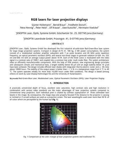
A practically unrestricted depth of focus, excellent color saturation, high contrast ratio and high resolution in<br />
combination with various video standards are the major advantages of <strong>laser</strong> <strong>projection</strong> systems compared to<br />
conventional lamp projectors. Each individual pixel is created by collinear superposition of three collimated <strong>laser</strong><br />
beams in the image. By consequence, the image stays also properly focused if the distance to the projector is varying<br />
or inclined or if curved surfaces are used as a <strong>projection</strong> screen. The <strong>laser</strong> wavelengths used cover more than 90 % of<br />
all colors which are perceptible by the human eye (Fig. 1).<br />
Fig. 1 Comparison of the color triangle of <strong>laser</strong> <strong>projection</strong> systems and traditional TV.
This is a significant improvement compared to conventional cathode emitter tubes (cathode-ray TV tube). The <strong>laser</strong><br />
radiation is characterized by its high spectral purity (small spectral linewidth) and its precise wavelength given by the<br />
atomic <strong>laser</strong> transition. For this reason, the color triangle remains stable without any readjustment, once generated,<br />
and white balancing can automatically be achieved by adjustment of the <strong>laser</strong> output powers <strong>for</strong> red, green and blue.<br />
Rapid advancement in the field of high power <strong>laser</strong> diodes in the 90ties has turned the idea of <strong>laser</strong> television into<br />
reality. Compared with <strong>laser</strong> <strong>projection</strong> systems <strong>for</strong> large image <strong>projection</strong> based on Argon-ion <strong><strong>laser</strong>s</strong> which required<br />
an electrical power of more than<br />
100 kW, solid state <strong><strong>laser</strong>s</strong> provide higher light output with a power consumption below 3 kW.<br />
The dream of a <strong>laser</strong> television <strong>for</strong> home cinema will come true when <strong>RGB</strong> semiconductor <strong><strong>laser</strong>s</strong> can be applied<br />
directly. The <strong>laser</strong> power required <strong>for</strong> home cinemas is in the order of several hundred mW up to one W per color.<br />
For a <strong>projection</strong> area of some tens of square meters, as required <strong>for</strong> <strong>projection</strong> in e-cinemas, planetarium or flight<br />
simulators etc., a <strong>laser</strong> power in the range of 5 to 20 W per color is required.<br />
There<strong>for</strong>e the demand <strong>for</strong> a highly effective and power-scaleable <strong>laser</strong> architecture provided the starting point <strong>for</strong><br />
ef<strong>for</strong>ts to design an all-solid-state <strong>RGB</strong> <strong>laser</strong> system. This challenge is being met under a development scheme <strong>for</strong> an<br />
<strong>RGB</strong> <strong>laser</strong> with optical parametric oscillator pursued in recent years by R. Wallenstein and coworkers at the University<br />
of Kaiserslautern 1 and brought to sophistication by Laser-Display-Technologie KG (LDT) in Gera, Germany.<br />
This paper reports on some results of developing a similar system to the industry-standard level. Various system<br />
components from color generation to modulation of the <strong>laser</strong> beams are described. The essential specifications of the<br />
<strong>laser</strong> light source are listed in Table 1.<br />
Parameter Specification<br />
Power<br />
446 nm<br />
532 nm<br />
628 nm<br />
> 4.8 W<br />
> 6.5 W<br />
> 7.0 W<br />
Pulse duration < 7 ps<br />
Pulse repetition frequency > 80 MHz<br />
Beam quality M² < 1.5<br />
Polarization > 100:1 (linear)<br />
Contrast ratio > 1,000 : 1<br />
Power stability<br />
< +/- 2 % over 8 h<br />
Amplitude noise<br />
< 2 % RMS<br />
Modulation frequency 32 MHz<br />
Expected lifetime 10000 h/5 years<br />
Electrical requirements 110 V/230 V, < 3 kW, 50 Hz/60 Hz<br />
Mechanical requirements Transportation on cars, ships and airplane<br />
Dimensions, weight<br />
Enviromental requirements<br />
1140*1150*600 mm³, 180 kg<br />
storage temperature range<br />
- 25 °C ... + 70 °C<br />
operating temperature range<br />
+ 5 °C ... + 40 °C<br />
humidity<br />
65 +/- 15 % at 25 °C<br />
Standards EN 60825-1, EN 60950, EN 50081(82)-1 class B, ISO 9000, CE<br />
Table 1 Specifications of the <strong>RGB</strong> <strong>laser</strong> system<br />
A modular structure based on individual, detachable and exchangeable subsystems is a prerequisite <strong>for</strong> serial<br />
manufacturing, testing and servicing of the complete <strong>laser</strong> system. In line with the modular structure, the modules<br />
and various subsystems are described in more detail. Besides the physical principles and main characteristics emphasis<br />
is on stability of the modules.
The <strong>RGB</strong> <strong>laser</strong> system consists of a fiber coupled diode <strong>laser</strong> pump module, a power supply, a diode current supply, a<br />
diode plug-in unit with a control subsystem, a cooling unit and a <strong>laser</strong> head. The complete <strong>RGB</strong> <strong>laser</strong> system is shown<br />
in Fig. 2.<br />
Fig. 2 <strong>RGB</strong> Laser System with dimensions of 1140*1150*600 mm³<br />
The <strong>laser</strong> head consists of six stages, a diode-pumped oscillator, a diode-pumped amplifier, an optical parametric<br />
oscillator, a non-linear frequency stage, a delay unit and a modulation unit with acoustooptic modulation, white<br />
color balancing and fiber coupling (Fig. 3). Modelocked pulses with a full-width-at-half-maximum (FWHM) of 7 ps<br />
and a wavelength of 1064 nm are amplified to an average output power of 42 W. Subsequently the pulses pass a<br />
non-linear crystal where part of the light is converted to green light (532 nm). The non-converted IR-power is partly<br />
used to synchronously pump an OPO and partly used <strong>for</strong> sum frequency mixing (SFM) with the OPO output at 1535<br />
nm. The generated red light (628 nm) is either mixed with the non-converted signal radiation to generate blue light<br />
at a wavelength of 446 nm or transmitted to yield the red output.<br />
Oscillator<br />
(1064 nm)<br />
SFM in LBO<br />
446 nm<br />
532nm<br />
462nm<br />
628nm<br />
AOM<br />
AOM<br />
AOM<br />
Amplifier<br />
SFM in KTA<br />
(628 nm)<br />
Fiber<br />
coupling<br />
SHG in LBO<br />
(532 nm)<br />
KTA OPO<br />
(1535 nm)<br />
Time-Delay<br />
Fig. 3 Principal schematic of the <strong>laser</strong> head<br />
A modelocked <strong>laser</strong> is used in the <strong>RGB</strong> system <strong>for</strong> two reasons: much higher peak intensities compared to continuous<br />
wave (cw) <strong><strong>laser</strong>s</strong> are achieved, which are necessary <strong>for</strong> efficient non-linear frequency generation. Secondly, provided<br />
the pulses are short enough (= 10 ps), no speckles are visible on the screen because of a broad spectrum and hence,<br />
the short coherence length.
2. FIBER COUPLED DIODE LASER PUMPING MODULE<br />
Fiber coupled diode <strong><strong>laser</strong>s</strong> are used as the pumping source <strong>for</strong> the <strong>RGB</strong> <strong>laser</strong>. By beam shaping of a diode array and<br />
then coupling the radiation into an optical fiber a flexible pumping source can simply be adapted to the oscillator and<br />
amplifier active elements. Through collimation of the fast axis of the <strong>laser</strong> beam and rearrangement of the beam by a<br />
pair of step mirrors, we coupled the emission of one high power diode <strong>laser</strong> array into an optical fiber of 600 µm<br />
core diameter and 0.22 N.A. The selected fiber coupling concept adds some important advantages to the <strong>RGB</strong> <strong>laser</strong><br />
system. The use of micro optics and quartz-quartz fibers guarantees long term stability of the <strong>laser</strong> parameters, a<br />
high coupling efficiency and allows <strong>for</strong> the separation of the fiber at the diode mount.<br />
2.1. Beam rearrangement<br />
The high power diode <strong><strong>laser</strong>s</strong> <strong>for</strong> cw operation are implemented as 10 mm wide semiconductor bars that are mounted<br />
to a heat sink and emit up to 30 W of cw optical power. There are distinct emission regions, each 150 µm wide,<br />
distributed along the <strong>laser</strong> bars with a filling factor of 30 %. The divergence angle along this axis (‘slow axis’) is<br />
approximately 10° (90 % power content). The height of the emitters is approximately 1 µm, corresponding to high<br />
divergence angle (about 80° at 90 % power content) along that direction (‘fast axis’). Calculating the beam<br />
parameter products (BPP) along the two axes one obtains 0.3 to 0.5 mm*mrad <strong>for</strong> the fast axis and approximately<br />
500 mm*mrad <strong>for</strong> the slow axis. To generate a circularly shaped beam suitable e.g. <strong>for</strong> fiber coupling, the BPP has to<br />
be made symmetrical. For rearrangement of the <strong>laser</strong> beam we apply a concept based on a pair of step mirrors 2,3,4 .<br />
This concept is licensed to JENOPTIK Laserdiode GmbH (JO LD) by the Fraunhofer Institute <strong>for</strong> Laser Technology in<br />
Aachen, Germany.<br />
2.1.1. Fast axis collimation<br />
In a first step the highly divergent radiation of the diode <strong>laser</strong> bar in the ‘fast’ direction is collimated by a cylindrical<br />
micro lens. Generally, there are no perfect lenses available that preserve the BPP. The utilization of high-refractive<br />
index aspheric lenses allow <strong>for</strong> the collimation of the fast axis to 5 mrad at a beam height of 0.6 mm with high<br />
efficiency equivalent to a BPP of 0.8 mm*mrad. The slow axis is not affected by this collimation.<br />
2.1.2. Rearranging of the <strong>laser</strong> radiation<br />
A pair of identical step mirrors with 13 steps divides the collimated radiation into 13 subbeams along the slow axis<br />
and arranges them one below the other. The BPP along the slow axis is diminished by a factor of 13 to approximately<br />
38 mm*mrad whereas along the fast axis it is increased by the same factor to 20 mm*mrad. The rearranged beam is<br />
much more symmetric regarding the BPPs than the radiation emitted directly from the diode <strong>laser</strong> (Fig. 4).<br />
Fig. 4 Scheme of symmetrization of BPP of a diode <strong>laser</strong> bar by means of a pair of step-mirrors. The first step mirror<br />
divides the 10 mm wide emission into 13 parts and shifts these along a 45° line (lower left). The second step mirror<br />
shifts the 13 parts so they are positioned one above the other.
2.1.3. Slow axis collimation and fiber coupling<br />
The slow axis is collimated by a conventional cylindrical lens (f = 40 mm) after the reordering of the step-mirrors. The<br />
result is a collimated beam of rectangular shape that can be focused (f = 20 mm) into an uncoated optical fiber. The<br />
fiber diameter and the numerical aperture are determined by the BPP of both symmetrical axes.<br />
2.2. Diode parameters and operating characteristics<br />
The pumping diode was developed as a pump source <strong>for</strong> the <strong>RGB</strong> <strong>laser</strong> head. The parameters (Table 2) are adapted<br />
to the special requirements of this application, but can be modified in terms of the wavelength, output power,<br />
monitoring, cooling system etc.<br />
Center wavelength 808 nm ± 1.5 nm<br />
Spectral breadth < 4 nm (90 % power content)<br />
Fiber coupling 600 µm core, N.A. 0.22<br />
Fiber output power 20 Watt<br />
Threshold current 8 ... 10 A<br />
Slope fibre output > 0.8 W/A<br />
Coupling efficiency > 75 %<br />
Monitoring inside of the housing PIN – Photodiode<br />
Table 2 Laser diode parameters.<br />
The <strong>laser</strong> diodes and the beam shaping optics are mounted on a copper plate and the housing is hermetically sealed.<br />
Peltier thermo electric elements are integrated into the mount. By means of pulse width modulation the temperature<br />
is stabilized to 0.1 K.<br />
The life time of the <strong>laser</strong> diode bars <strong>for</strong> cw–operation at an output power of 50 W has been investigated and<br />
determined to be > 20,000 hours (Fig. 5). In the <strong>RGB</strong> <strong>laser</strong> system the diodes are typically operated at an output<br />
power of the diode bar of 16 W. Several aspects can influence the degradation behavior. Early failures of <strong>laser</strong> diodes<br />
are regularly identified during the burn-in tests. The cooling and control system as well as the mounting technology<br />
<strong>for</strong> all components guarantees heat dissipation and constant temperature of the <strong>laser</strong> bar over the whole life time. A<br />
hermetically sealed housing prevents degradation due to humidity or chemical vapors. A life time test with the plugin<br />
unit of the <strong>RGB</strong> <strong>laser</strong> system including 9 fiber coupled <strong>laser</strong> diodes (Fig. 6) is in progress.<br />
Power / W<br />
60<br />
50<br />
40<br />
30<br />
20<br />
10<br />
0<br />
JENOPTIK Laserdiode GmbH<br />
0.25 W/1000h -> 45082h<br />
0.27 W/1000h -> 41145h<br />
0.74 W/1000h -> 14806h<br />
0.67 W/1000h -> 16079h<br />
0 1000 2000 3000 4000 5000<br />
Time / h<br />
Fig. 5 Lifetime measurement of <strong>laser</strong> diodes at 808 nm
Fig. 6 Fiber coupled module with integrated TEC and the plug-in unit with 9 fiber coupled <strong>laser</strong> diodes<br />
3. MODELOCKED OSCILLATOR<br />
The modelocked oscillator is pumped by a fiber coupled diode <strong>laser</strong>. The fiber core size is 600 µm and the power<br />
content is 99.6 % at a numerical aperture of 0.22. The <strong>laser</strong> crystal is longitudinally pumped to match the pump<br />
beam to the <strong>laser</strong> beam. The mode size of the fiber is focused with a 1:1.1 optics to a beam diameter of<br />
approximately 660 µm inside the <strong>laser</strong> crystal which is slightly smaller than the calculated mode size in the <strong>laser</strong> crystal.<br />
The output beam is TEM 00 with a measured M 2 -value of 1.0 in both directions (Fig. 7).<br />
P <strong>laser</strong> /W, M², 2w 0 /mm<br />
8,0<br />
7,0<br />
6,0<br />
5,0<br />
4,0<br />
3,0<br />
2,0<br />
1,0<br />
0,0<br />
P/W<br />
M²x<br />
M²y<br />
2w0x<br />
2w0y<br />
0 1 2 3 4 5 6 7 8 9 10 11 12 13 14<br />
Fig. 7 Oscillator output power and beam quality<br />
The active material is a 8 mm long Nd:YVO 4 crystal with a Nd atomic concentration of 0.7 %. Nd:YVO 4 was chosen<br />
because of the high gain emission cross section (s = 15.6*10 -19 cm 2 at 1.1 atomic %, a-cut), the broad absorption<br />
bandwidth (15.7 nm) which makes it an ideal candidate <strong>for</strong> diode pumping, and the broad emission bandwidth of<br />
1.0 nm which supports pulse widths below 10 ps 15 . Pulse widths in the fs-regime would be attainable with Nd:glass<br />
materials, but this would dramatically increase the demands on the stability of the length adjustments of the<br />
synchronically pumped OPO and the subsequent non-linear processes. A disadvantage of Nd:YVO 4 is the high<br />
thermal lensing coefficient h with<br />
h<br />
α<br />
=<br />
κ<br />
P pump/W<br />
dn<br />
dT
where a is the absorption coefficient, ? the thermal conductivity, and dn/dT the change in refractive index as a<br />
function of the temperature. With a = 31.4 cm -1 (at 808 nm and 1.1 % atomic %, a-cut), ? = 5.1 W/(m*K), and dn/dT<br />
= 3*10 -6 K -1 (at 808 nm and 1.1 % atomic %, a-cut), a thermal lensing coefficent of h = 1.8*10 -3 W -1 is obtained<br />
which is theoretically four times bigger in comparison to Nd:YAG 15 . For this reason, special care was taken to design<br />
the resonator to be as stable as possible against thermal lensing effects, i.e., the resonator was optimized with<br />
respect to the invariance of the mode size in the <strong>laser</strong> crystal against changes in the strength of the thermal lens. For<br />
a thermal lens between 300 and 1,100 mm effective focus length, the mode size changes by only 10 %.<br />
Passive modelocking with a semiconductor saturable absorber was chosen 5,6 to guarantee the stability and robustness<br />
which is necessary <strong>for</strong> industrial applications. Using enhanced spatial hole-burning 7,8 a minimum pulse width of 6 ps<br />
was achieved (Fig. 8). If the <strong>laser</strong> crystal was moved away from the mirror, the pulse widths increased up to a factor<br />
of 2. Depending on the design of the saturable absorber and the mode size on the sample the modelocked Qswitching<br />
threshold was measured to be between 0.5 W and 2 W 9 .<br />
autocorrelation signal / a.u.<br />
1<br />
0,8<br />
0,6<br />
0,4<br />
0,2<br />
0<br />
-20 -15 -10 -5 0 5 10 15 20<br />
Delay / ps<br />
Fig. 8 Autocorrelation signal of oscillator pulse<br />
The ratio between the modelocked IR-output power (4.5 W) and the pump power at the fiber end (10 W) was 45 %.<br />
The diode was operated at 22 A and 1.9 V, i.e. the total electrical to optical efficiency was 10.8 %. Due to the broad<br />
absorption bandwidth of Nd:YVO 4 the output power of the <strong>laser</strong> was stable up to +/- 0.5 % <strong>for</strong> a realized<br />
temperature stability of ± 0,2 K.<br />
The geometrical size of the oscillator is 700 x 80 mm 2 . The resonator is stabilized to < 50 µm to guarantee the length<br />
stability of the oscillator-OPO system even without an active length control.<br />
4. AMPLIFIER<br />
data<br />
Fitfunction(sech^2)<br />
6 ps FWHM<br />
The <strong>laser</strong> crystal Nd:YVO 4 has been described in the literature 10,11,12,13,14 as an effective <strong>laser</strong> and amplifier <strong>laser</strong> material<br />
<strong>for</strong> continuous wave, high repetition rate Q-switched and modelocked TEM 00 <strong>laser</strong> operation. Laser designs include<br />
longitudinal pumped rods, side pumped slabs and the thin disc <strong>laser</strong> approach.<br />
The design of Nd:YVO 4 amplifiers must also consider the low thermal conductivity of Nd:YVO 4. Consequently an<br />
approach with 4 amplifier stages has been chosen in this work. The amplifiers are longitudinally pumped . . Total<br />
optical efficiency of the amplifier stages is about 40 %.<br />
The output power of the modelocked oscillator is 4.5 W. The Faraday isolator is used to isolate the oscillator from<br />
feedback to obtain stable modelocking. The first amplifier stage has an amplification of 2.5 leading to an output<br />
power of about 12 W. The second to <strong>for</strong>th amplifier are operating in gain saturation, thus leading to additional 10 W<br />
of output power per stage, resulting in a total power of 42 W at the output beam of the amplifier system.
To achieve high efficiency and beam quality simultaneously, a careful matching between the output beam waist of<br />
the oscillator and the optimum beam waist of the amplifier stages has to be considered. Additionally the intensity of<br />
the input beam of the amplifiers has to be optimized <strong>for</strong> maximum gain.<br />
The beam path in the amplifier system has been carefully modelled by using of FEM and commercial beam<br />
propagation software. Modematching is such that it leads to a waveguide structure of modematching lenses and the<br />
thermal lenses inside the <strong>laser</strong> crystals act as focusing elements. The focal length of the <strong>laser</strong> crystals is in the order of<br />
120 mm. The beam waist of the output beam is 2ω o = 0.5 mm. The experimental beam parameters correspond to<br />
the calculated values to better than 10 %. The output beam parameters are M² = 1.2, measured with a Coherent<br />
Modemaster, the output power being 42 W. The complete amplifier system is integrated on a breadboard with a<br />
footprint of 330 x 240 mm².<br />
5. OPTICAL PARAMETRIC OSCILLATOR (OPO)<br />
The key component <strong>for</strong> generation of red and blue light is the synchronously pumped noncritically phase-matched<br />
potassium titanyl arsenate (KTA) optical parametric oscillator (OPO) as described in 16 .<br />
The signal resonant OPO cavity is generating a signal wave at 1535 nm and an idler wave at 3470 nm. Whereas the<br />
idler wave is not used <strong>for</strong> further frequency conversion the signal output is essential to the generation of red (629<br />
nm) and blue (446 nm) light. There<strong>for</strong>e stable operation of the OPO is an important demand. Since the OPO is<br />
synchronously pumped one has to avoid any length mismatch between the OPO and the <strong>laser</strong> resonator.<br />
The influence of OPO resonator length changes on the signal pulse power and duration is shown in Fig. 9. In this<br />
figure, the point ΔL = 0 (no length mismatch) is determined by the maximum of the signal power. The power and<br />
pulse duration are normalized to the values at this point. The behavior of the dependencies as depicted in Fig. 9 can<br />
be explained by the change of the overlap of the resonant signal pulse and the pump pulse in the KTA crystal and<br />
taking into account different group velocities of the interacting signal, idler and pump pulses within the crystal.<br />
Normalized Power and Pulse Duration<br />
1,2<br />
1,1<br />
1<br />
0,9<br />
0,8<br />
0,7<br />
0,6<br />
0,5<br />
-700 -600 -500 -400 -300 -200 -100 0 100 200<br />
Change of Resonator length / µm<br />
maximum tolerable range of resonator length<br />
Normalized Power P/Pmax(0) Normalized Pulse Duration TP/TP(0)<br />
Fig. 9 Measured signal pulse duration and power in dependence of OPO resonator length changes<br />
The allowed resonator length change ΔL acc can be estimated by the condition that the power drop must be less than<br />
5 % and the pulse duration increases less than 10 % which is important <strong>for</strong> the subsequent frequency mixing<br />
processes. From Fig. 9, it follows that the overall tolerable resonator length change is approximately 200 µm.<br />
Accordingly, the maximum allowed length variations of the folded resonator has to be smaller than 50 µm. To<br />
operate within the allowed length variation, a thermal stabilization of the aluminum base plate (thermal expansion<br />
coefficient about 25*10 -6 ) of ± 1 K is necessary.
Besides stable output the goal is an OPO efficiency P(signal)/P(pump) ≥ 40 %. This value corresponds to a pump pulse<br />
duration of about 7 ps (FWHM).<br />
Use of the idler or non-converted pump wave is not possible. Due to the large wavelength difference, mode<br />
matching in the nonlinear crystal would be difficult to achieve and the temporal pulse shape of transmitted, depleted<br />
pump light is typically distorted and strongly depends on the OPO resonator length, i. e. further frequency mixing<br />
becomes unstable.<br />
6. SUM-FREQUENCY GENERATION<br />
The generation of the green beam is realized by single pass frequency doubling of 1.064 µm. The generation of 629<br />
nm and 446 nm is achieved by sum frequency generation (SFM) as schematically depicted in Fig. 10 and published in<br />
Ref. 1 . Red radiation (629 nm) is generated by mixing the OPO signal (1.535 µm) with the <strong>laser</strong> radiation (1.064 µm) in<br />
a critically phase-matched KTA-crystal which has been proven to be the favorable nonlinear material (higher<br />
conversion efficiency than LBO, small walk-off angle of 0.1° which does not distort the beam profile). The blue beam<br />
(446 nm) is produced by SFM of the red light with the residual OPO signal radiation in a critically phase-matched LBO<br />
crystal which turned out to be the best material in comparison with BBO and RTA (no absorption, small walk-off<br />
angle of 0.6°).<br />
Fig. 10 Nonlinear frequency conversion unit with dimensions of 370 x 340 mm².<br />
It is reasonable to start with given <strong>RGB</strong> powers as fixed in the specs (7.0/6.5/4.8 W) and to look backwards what<br />
overall <strong>laser</strong> power is needed. This is illustrated in the 3-D-plot of Fig. 11. The surface depicts the <strong>laser</strong> power which is<br />
necessary to reach the <strong>RGB</strong> power specifications depending on the efficiency of sum frequency mixing processes<br />
“red“ (η red) and “blue“ (η blue) <strong>for</strong> a given OPO efficiency of 45 %. For small η red, η blue a very high value of <strong>laser</strong> power is<br />
necessary, but the slope is decreasing quickly <strong>for</strong> increasing efficiencies and running out relatively flat <strong>for</strong> efficiencies<br />
> 50 %. A pump power at the 40-W-level and below which is indicated as dark area in the surface plot of Fig. 11 is<br />
sufficient <strong>for</strong> (η blue,η red) ≥ (30 %, 50 %). Both values are realized with our crystals at optimum focussing conditions.<br />
The overall efficiency of conversion from 1.064 µm to <strong>RGB</strong> is thus nearly 50 %.
0.1<br />
0.2<br />
Efficiency "Blue"<br />
0.3<br />
0.4<br />
0.5<br />
0.6<br />
0.3<br />
0.35<br />
0.4<br />
0.45<br />
0.5<br />
0.55<br />
0.6<br />
0.65<br />
0.7<br />
0.75<br />
0.8<br />
Efficiency "Red"<br />
Fig. 11 IR <strong>laser</strong> power <strong>for</strong> specified <strong>RGB</strong> output in dependence of efficiencies of SFM processes<br />
<strong>for</strong> OPO efficiency of 45 %<br />
7. MODULATION UNIT<br />
The modulation of <strong>RGB</strong> light is realized by acusto-optical modulators (AOM) instead of previously used electro-optical<br />
modulators (EOM). A very high contrast ratio of better than 1:1,000 (EOM: < 1:500), a small modulation voltage of<br />
about<br />
1 V (EOM: 200 V), small dimensions of about 10 cm 3 only (EOM: 50 cm 3 ) and easier alignment are the advantages of<br />
AOM over EOM. The AOM has a carrier frequency of 180 MHz and a diffraction efficiency of 75 %. The red, green<br />
and blue beams are modulated with a maximum frequency of 32 MHz. Fig. 12 shows the modulation unit which<br />
includes the AOMs, the white light balancing, an active angle and position stabilization system of the three beams<br />
and the fiber coupling optics.<br />
Fig. 12 Modulation unit with dimensions of 300 x 500 mm²<br />
40<br />
20<br />
0<br />
120<br />
100<br />
80<br />
60<br />
180<br />
160<br />
140<br />
Power/W<br />
160-180<br />
140-160<br />
120-140<br />
100-120<br />
80-100<br />
60-80<br />
40-60<br />
20-40<br />
0-20
8. OPTO MECHANICAL DESIGN CRITERIA<br />
Different materials have been tested with respect to angle stability as a function of temperature. The objective of<br />
these experiments was to find a highly mechanically and thermally stable mirror mount. Four different types of twoaxis<br />
flexure mounts were tested. The first type (type I) was machined from a single piece of high-grade steel<br />
(X5CrNi18.10). Type II - IV were made from two pieces of metal, mounted together with 4 screws. Type II was made<br />
from aluminum (AlMg4,5), type III from brass (CuZn39Pb3), and type IV from high-grade steel (X5CrNi18.10).<br />
To measure the thermal stability, the mounts were exposed <strong>for</strong> several times to a temperature shift from + 25 °C to –<br />
25 °C or from + 25 °C to + 75 °C, kept at this temperature <strong>for</strong> one hour, and then heated (cooled) back to the<br />
original temperature of + 25 °C. Be<strong>for</strong>e and after each temperature cycle, the tilt between the mirror and a reference<br />
plane was measured with an autocollimating telescope. On average (heat and cooling exposures, x- and y-plane,<br />
different test cycles) the mean square deviation was 0.63 arc minutes <strong>for</strong> type I, 0.32 arc minutes <strong>for</strong> type IV, 0.054<br />
arc minutes <strong>for</strong> type II and 0.022 <strong>for</strong> type II, i.e., the hysteresis effect after temperature cycles of brass and aluminum<br />
is about an order of magnitude better than with steel. Note that this is not a measure <strong>for</strong> the angle tilt in warm or<br />
cold environment, but a measure <strong>for</strong> how good the system returns its original state after exposure to cold or warm<br />
conditions (during transport or storage). The whole system is mounted on a base plate, which is temperature<br />
stabilized during operation.<br />
To determine the relationship between the mechanical stability and the stability of the lasing system we measured<br />
the stability of the output power as a function of the angle misalignment <strong>for</strong> a folding mirror. A power degradation<br />
of 5 % occured at a tilt angle of 1 arc minute. It can be concluded that hysteresis effects of the mirror mounts are<br />
well below the critical values of major changes in the <strong>laser</strong> output power.<br />
To check the mechanical stability we per<strong>for</strong>med a number of vibration- and shock tests (Table 3):<br />
Shock Continuous shock Vibration<br />
Stimulation half-sinusoidal Half-sinusoidal Sinusoidal with sliding<br />
frequency<br />
Load 30 g/6 ms 10 g/6 ms 0.15 mm/2 g<br />
Quantity 3 per direction 1000 per direction 10 cycles per direction<br />
Direction 2 (+/- position of use) 2 (+/- position of use) 1 (position of use)<br />
Rate 1 octave/min<br />
Frequency 10 Hz – 2000 Hz – 10<br />
Hz<br />
(1 cycle)<br />
Table 3: Tests <strong>for</strong> mechanical stability.<br />
All types showed comparably good results: type I – 0.13 to 0.32 arc minutes, type II – 0 to 0.067 arc minutes, type III<br />
– 0.067 to 0.13 arc minutes and type IV – 0.13 arc minutes. In general, the effects due to mechanical stress were by<br />
an order of magnitude smaller than thermal effects. Again, aluminum and brass showed slightly better results,<br />
compared to steel.<br />
9. SUMMARY<br />
An industrial all-solid state Red-Green-Blue <strong>laser</strong> system <strong>for</strong> large image <strong>projection</strong> systems is presented. The start of<br />
serial production is scheduled <strong>for</strong> the summer of 2000.<br />
10. ACKNOWLEDGMENTS<br />
This work was carried out by a contract with Laser-Display-Technologie GmbH and supported by the Ministry of<br />
Economy of the German State of Thuringia. The authors gratefully acknowledge fundamental work by R. Wallenstein<br />
and his colleagues and the helpful discussions with C. Deter and J. Kraenert.
REFERENCES<br />
1. A. Nebel, B. Ruffing, R. Wallenstein, “A high power diode-pumped all-solid-state <strong>RGB</strong> <strong>laser</strong> source”, in<br />
Conference on Lasers and Electro-Optics, Vol. 6, 1998 OSA Technical Papers Series (Optical Society of America,<br />
Washington D.C., 1998), Postdeadline Papers CPD3.<br />
2. K. Du, M. Baumann, B. Ehlers, H.G. Treusch, P. Loosen: "Fiber-coupling technique with micro step-mirrors <strong>for</strong><br />
high-power diode <strong><strong>laser</strong>s</strong> bars", OSA TOPS Vol. 10 (C.R. Pollack, W.R. Bosenberg, eds.), pp. 390-393, 1997.<br />
3. M. Baumann, B. Ehlers, M. Quade, K. Du, H.G. Treusch, P. Loosen, R. Poprawe: "Compact fibre-coupled highpower<br />
diode-<strong>laser</strong> unit", SPIE Vol. 3097 (L.H.J.F. Beckmann, ed.), pp. 712-716, 1997.<br />
4. Patent no. DE 44 38 368 (1996) and international applications.<br />
5. U. Keller, D. A. B.Miller, G. D. Boyd, T. H. Chiu, J. F. Ferguson, M. T. Asom, “Solid-state low-loss intracavity<br />
saturable absorber <strong>for</strong> Nd:YLF <strong><strong>laser</strong>s</strong>: an antiresonant semiconductor Fabry-Perot saturable absorber,“ Optics<br />
Lett.,<br />
vol. 17, pp. 505-507, 1992.<br />
6. L. R. Brovelli, I. D. Jung, D. Kopf, M. Kamp, M. Moser, F. X. Kärtner, U. Keller, „Self-starting soliton modelocked<br />
Ti:sapphire <strong>laser</strong> using a thin semiconductor saturable absorber,“ Electronics Lett., vol. 31, pp. 287-289, 1995.<br />
7. B. Braun, K. J. Weingarten, F. X. Kärtner, and U. Keller, “Continuous-wave modelocked solid-state <strong><strong>laser</strong>s</strong> with<br />
enhanced spatial hole-burning, Part I: Experiments,“ Applied Physics B, vol. 61, pp. 429-437, 1995.<br />
8. F. X. Kärtner, B. Braun, and U. Keller, “Continuous-wave modelocked solid-state <strong><strong>laser</strong>s</strong> with enhanced spatial<br />
hole-burning, Part II: Theory,“ Applied Physics B, vol. 61, pp. 569-579, 1995.<br />
9. F. X. Kärtner, L. R. Brovelli, D. Kopf, M. Kamp, I. Calasso, U. Keller, “Control of solid-state <strong>laser</strong> dynamics by<br />
semiconductor devices,“ Optical Engineering, vol. 34, pp. 2024-2036, 1995.<br />
10. W.L. Nighan, Jr., N. Hodgson, “Quantum-limited 35 W, TEM 00, Nd:YVO 4 <strong>laser</strong>“, in Conference on Lasers and<br />
Electro-Optics, OSA Technical Papers Series (Optical Society of America, Washington DC, 1999), p.1<br />
11. L.Gonzales, K.Kleine, L.Marshall, “High Brightness MOPA“, in Conference on Lasers and Electro-Optics, OSA<br />
Technical Papers Series (Optical Society of America, Washington DC, 1999), pp.1-2.<br />
12. G. Hollemann, H. Zimer, A.Hirt, “Pulsed-mode operation of a diode-pumped Nd:YVO 4 thin disc <strong>laser</strong>“, in<br />
Conference on Lasers and Electro-Optics, Vol. 6, 1998 OSA Technical Papers Series (Optical Society of America,<br />
Washington D.C., 1998), pp. 543-544.<br />
13. K.J.Snell, D. Lee, J.G. Manni, “High-Average Power, High-Repetition Rate, Side-Pumped Nd:YVO 4 Slab Laser<br />
MOPA System“, in Conference on Lasers and Electro-Optics, OSA Technical Papers Series (Optical Society of<br />
America, Washington DC, 1999), Postdeadline Papers CPD1.<br />
14. J.E.Bernard, A.J.Alcock, “High-repetition-rate diode-pumped Nd:YVO 4 slab <strong>laser</strong>“, Optics Letters 19, 1861<br />
(1994).<br />
15. W.Koechner, “Solid State Laser Engineering“, Springer Series in Optical Siences, A.L. Schawlow, A.E. Siegman,<br />
T.Tamir, edts., Fifth Edition, Springer Berlin, 1999, pp. 48-61.<br />
16. B. Ruffing, A. Nebel, R. Wallenstein, Paper MF3-1,”High-Power all-solid-state cw mode-locked picosecond KTA<br />
optical parametric oscillator”, Advanced Solid-State Lasers, 12 th Topical Meeting, Jan. 27-29, 1997, Orlando,<br />
Florida.