T H E M A G A Z I N E - Mines Magazine - Colorado School of Mines
T H E M A G A Z I N E - Mines Magazine - Colorado School of Mines
T H E M A G A Z I N E - Mines Magazine - Colorado School of Mines

You also want an ePaper? Increase the reach of your titles
YUMPU automatically turns print PDFs into web optimized ePapers that Google loves.
Controlled Particle<br />
Movement In<br />
Counter-Current<br />
'low Heating<br />
By<br />
HARRY K. SAVAGE<br />
Research indicates that the current method <strong>of</strong> heating<br />
broken solids with hot gas by counter-current flow<br />
can be made more effective. To design and operate<br />
equipment for the purpose will require a knowledge <strong>of</strong><br />
how broken solids flow. Closely associated with flow<br />
is the feature <strong>of</strong> agitating in some degree a mass <strong>of</strong><br />
broken solids, using no other force than gravity.<br />
Little work has been done on the flow <strong>of</strong> broken<br />
sohds until in recent years (1), (2). The following data<br />
are <strong>of</strong>fered as a contribution to a better understanding<br />
<strong>of</strong> the subject.<br />
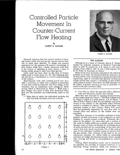
Experimental work with crashed gravel was done<br />
with a container, so built, that a desired cross-section<br />
<strong>of</strong> rock flow could be obsei'ved. The floor design <strong>of</strong> the<br />
container was an adaptation from mining by block<br />
caving which is illustrated by Figure 1. With such a<br />
floor design, two types <strong>of</strong> flow were developed when<br />
flow into the container was substantially equal to out<br />
flow:<br />
22<br />
1—Mass flow in which the individual particles fell<br />
with but httle deviation from the vertical.<br />
Figure I.<br />
THE<br />
HARRY K. SAVAGE<br />
AUTHOR<br />
Although he is a native <strong>of</strong> <strong>Colorado</strong>, Harry K. Savage<br />
received his technical education ai Stanford University<br />
where in 1907 he received his A.B. degree in civil engineering.<br />
From 1920 to 1931 he was a field engineer for<br />
D. D. Potter & Associates <strong>of</strong> Denver.<br />
Early in his career he became interested, in the technical<br />
problems <strong>of</strong> oil shale. He discovered that the utilization <strong>of</strong><br />
oil shale will he a close combination <strong>of</strong> mining and chemical<br />
engineering. Later he concluded that efficient retorting by<br />
counter-current flow requires a knowledge <strong>of</strong> how broken<br />
solids behave in motion. Since there was little literature on<br />
the subject, it became necessary for him to undertake research<br />
on the flow <strong>of</strong> broken solids.<br />
2—Cone flow in which the particles fell at different<br />
rates and directions, mostly non-vertical.<br />
Mass flow was obtained by opening simultaneously<br />
all the outlets shown by Figure 1. This flow is illustrated<br />
by Figure 2 which is a cross section, A-A <strong>of</strong> Figure 1.<br />
Above B-B <strong>of</strong> Figure 2, flow did not indicate any stress<br />
except in the vicinity <strong>of</strong> the sidewalls where friction<br />
caused a variation in velocity. This created shear and<br />
potential tension in that vicinity. Below B-B, mass<br />
flow was gradually superseded by cone flow with increased<br />
shear and tension as the outlets were approached.<br />
Mass flow, because <strong>of</strong> its stabiMty and lack <strong>of</strong> independent<br />
particle movement, is not conducive to rapid<br />
heating by counter-current methods. Technical literature<br />
on the subject, (3), states that only a portion <strong>of</strong><br />
the voids in broken solids are available as gas carriers<br />
because many <strong>of</strong> them are blocked by overlying pieces<br />
<strong>of</strong> solid material and by interlocking. It has been estimated<br />
that only about one-fourth, (4), <strong>of</strong> the surface<br />
area <strong>of</strong> the individual particles comes in contact with<br />
the gas stream. Also, volumes <strong>of</strong> gas tend to set up<br />
convection currents, (5), which result in channeling<br />
and slow up further the heating process. Given enough<br />
time, heating wiU finally be accompfished by indirect<br />
means.<br />
Caking, which sometimes occurs, can be minimized<br />
by agitating the particles at frequent intei-vals or by<br />
removing caking mediums, which are products <strong>of</strong><br />
THE MINES MAGAZiNE • MARCH, 1960<br />
distillation, by the use <strong>of</strong> a sufficient amount <strong>of</strong> scavenging<br />
gases. Mass flow in the main is inimical to either<br />
<strong>of</strong> these methods.<br />
On the other hand, cone flow produces varying conditions<br />
<strong>of</strong> velocity and direction. These induce individual<br />
particle movement and produce stress. This<br />
tends to break up static features in a bed <strong>of</strong> broken<br />
solids. This type <strong>of</strong> flow can be induced in a container<br />
<strong>of</strong> broken sohds by outlet flow through a single orifice.<br />
Its location in regard to the sidewalls will determine<br />
the pattern <strong>of</strong> flow. An orifice in the center <strong>of</strong> the<br />
bottom will produce a balanced inverted cone as shown<br />
by Figure 3. li in any other position, flow may be influenced<br />
by the sidewalls. If so, the flow pattern will<br />
be that <strong>of</strong> an imbalanced cone as illustrated by Figures<br />
4 and 5.<br />
Height <strong>of</strong> the container in relation to its width is<br />
another important factor. If the height is about two<br />
and one-half times the width, flow at that point and<br />
above, if the container is higher, will be similar to mass<br />
flow shown above B-B by Figure 2. Below the critical<br />
height there will be a combination <strong>of</strong> mass and cone<br />
flow with the latter increasing in proportion until mass<br />
flow ceases and cone flow takes over completely. As<br />
mass flow diminishes shear and tension increase. The<br />
cone-flow pattern will be that <strong>of</strong> an inverted cone<br />
flowing thi-ough an upright cone-like figure <strong>of</strong> static<br />
material. The line <strong>of</strong> contact between the two cones <strong>of</strong><br />
broken rock will be at an angle <strong>of</strong> 70° from the horizontal,<br />
(Figure 3). Different materials have different<br />
flow angles; catalyst pellets 71", (6): a good grade <strong>of</strong><br />
oil shale, 72^ (7).<br />
\<br />
\<br />
A \<br />
7\-<br />
/ - \<br />
^ L \<br />
"I<br />
F/ovf/fty JbfBX^ rock<br />
/ \<br />
/ \<br />
/ \<br />
/ A \<br />
L A L<br />
* 3<br />
Figure 2.<br />
I \<br />
I<br />
THE MINES MAGAZINE • MARCH, 1960<br />
V<br />
/''<br />
11<br />
111<br />
I n<br />
///<br />
I<br />
I<br />
I<br />
I A<br />
When flow was through outlet #1, (Figure 1), the<br />
pattern was that <strong>of</strong> an imbalanced cone, (Figure 4).<br />
The pattern was quite different from that <strong>of</strong> a balanced<br />
cone, {Figure 3), one side <strong>of</strong> the imperfect cone<br />
was heavier than the other with the lighter side being<br />
between the center <strong>of</strong> the cone and the side wall. When<br />
flow began through outlet #1, the initial flow in the<br />
upper part <strong>of</strong> the cone was toward the side wall rather<br />
than toward the outlet. Soon most <strong>of</strong> the material<br />
changed direction toward the outlet, but part <strong>of</strong> it<br />
as shown by markers 2, 3 and 4, continued toward<br />
thc side wall until near the bottom <strong>of</strong> the container.<br />
It then changed direction rather abruptly to flow to<br />
the outlet. The peculiarities <strong>of</strong> this type <strong>of</strong> flow indicates<br />
greater shear and tension than that <strong>of</strong> Figure 3.<br />
_ When outlet #1 was closed and outlet #2 opened a<br />
different type <strong>of</strong> imbalanced cone flowed as illustrated<br />
by Figure 6. It was more nearly in balance than the<br />
cone illustrated by Figure 4-<br />
Draw thi-ough outlets 1, 4, 13 and 16 will produce<br />
imbalanced cones with similar patterns. Draw through<br />
outlets 2, 3, 5, 8, 9, 12, 14 and 15 wifl produce imbalanced<br />
cones with patterns similar to Figure 6. Draw<br />
through outlets 6, 7, 10, 11 may produce balanced<br />
cones similar to Figure 3. If all the cones were drawn<br />
• Figure 3.<br />
23