Download File > GT_Series.pdf - FHP Manufacturing
Download File > GT_Series.pdf - FHP Manufacturing
Download File > GT_Series.pdf - FHP Manufacturing

You also want an ePaper? Increase the reach of your titles
YUMPU automatically turns print PDFs into web optimized ePapers that Google loves.
<strong>GT</strong>/GS SERIES<br />
HEATING AND AIR CONDITIONING EQUIPMENT
<strong>FHP</strong> <strong>Manufacturing</strong> is dedicated to building quality<br />
heating and cooling products designed specifically with<br />
your home in mind. Our commitment to deliver the<br />
highest quality water source and geothermal systems is<br />
the primary focus of our entire management and engineering staff.<br />
For nearly three decades Florida Heat Pump has manufactured<br />
quality heating and cooling equipment for both residential and<br />
commercial applications and continues to be the industry leader.<br />
Florida Heat Pump (<strong>FHP</strong>) is one of the only heating and air<br />
conditioning manufacturers dedicated solely to water source and<br />
geothermal technology. This dedication shows in each individual<br />
unit that is produced in our nearly 100,000 Ft 2 facility in Fort<br />
Lauderdale, Florida. <strong>FHP</strong> delivers equipment to all corners of the<br />
world and continues to be the model of reliability while maintaining<br />
the best “quick ship” production facility in the industry.<br />
<strong>FHP</strong> has the same management team since our origin in 1969, which provides our company the stability in the marketplace that no other manufacturer<br />
can match. All of our products are safety listed by Underwriters Laboratories Inc. (UL) and performance certified by the Air-Conditioning & Refrigeration<br />
Institute (ARI) for your piece of mind. <strong>FHP</strong> offers a wide range of equipment sizes, cabinet configurations, and factory installed options that provide the<br />
versatility to meet your needs. We offer vertical, horizontal, counter-flow, and split system forced air models as well as water to water hydronic<br />
equipment. You can relax in year round comfort and enjoy energy savings with Florida Heat Pump products.<br />
<strong>FHP</strong> understands that your purchase of a water source or geothermal heating and air conditioning system is a major expense and before you make<br />
any major purchasing decision you should do your homework, therefore we encourage you to visit the following web sites for extensive information<br />
about this technology and how it can help you.<br />
www.fhp-mfg.com<br />
www.geoexchange.org<br />
www.igshpa.okstate.edu<br />
www.epa.gov/appdstar/hvac/geothermal.html<br />
www.eren.doe.gov/geothermal<br />
The Industry Leader<br />
<strong>FHP</strong> <strong>Manufacturing</strong> Company (Florida Heat Pump)<br />
Geothermal Heat Pump Consortium<br />
International Ground Source Heat Pump Association<br />
U.S. Environmental Protection Agency<br />
U.S. Department of Energy<br />
<strong>GT</strong>/GS <strong>Series</strong> Features es Solid State<br />
Controls ols At An Affordable fordable Price<br />
The UPM Solid State controller is designed to enhance the operation and add to the features of<br />
traditional electromechanical controls. The UPM controller incorporates the standard functions of<br />
the electromechanical controls while adding several useful features commonly needed in water<br />
source and geothermal heat pump applications.<br />
• RANDOM START - Each controller has a unique random start feature<br />
programmed into its microprocessor.<br />
• ANTI-SHORT CYCLE TIMER - 5 minute delay on break timer to<br />
prevent compressor short cycling.<br />
• LOW PRESSURE BYPASS TIMER - Bypasses the low pressure<br />
switch for 90 seconds to avoid nuisance lockouts during cold start up.<br />
• HIGH PRESSURE SWITCH DELAY - One (1) second delay provides<br />
switch stabilization on start up to prevent nuisance lockouts.<br />
• BROWNOUT/SURGE/POWER INTERRUPTION PROTECTION - a<br />
20 millisecond window is monitored for the above condition. After the<br />
condition is detected the 5-minute delay on break timer is initiated in<br />
conjunction with the random start timer before a restart is allowed. This<br />
allows for the water pumps to restart and establish water flow to<br />
prevent nuisance lockouts during brief power interruptions.<br />
• MALFUNCTION OUTPUT - The controller has a set of wet contacts<br />
for remote fault indication.<br />
• TEST/SERVICE PIN - A jumper PIN is provided to reduce all time<br />
delay settings to 6 seconds during troubleshooting or operation<br />
verification.<br />
• L.E.D. INDICATORS - Two L.E.D. INDICATORS are provided<br />
as follows:<br />
GREEN: Power L.E.D. indicates voltage is present at the board.<br />
RED: Fault indicator will blink code.<br />
• INTELLIGENT RESET - If a fault condition is initiated the<br />
5 - minute delay on break time period and the random start<br />
timer are initiated and the unit will restart after the delays<br />
expire. If the same fault condition is initiated a second time,<br />
the unit will be locked out and requires lockout reset.<br />
• LOCKOUT RESET - Power must be removed from the<br />
controller then reapplied for the reset. This can be achieved<br />
via the thermostat or by the unit disconnect.
<strong>GT</strong>/GS <strong>Series</strong> Features<br />
es<br />
1) Heavy gauge Galvalume ® plus finish cabinet with corrosion-resistant<br />
aluminum-zinc alloy and a clear acrylic coating for additional protection.<br />
2) Optional factory installed and wired emergency electric heater.<br />
3) Oversized blower with dynamically balanced wheel for whisper<br />
Quiet Operation.<br />
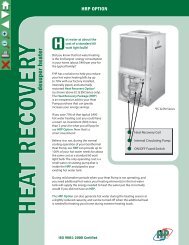
4) Optional factory installed heat recovery system that can provide<br />
virtually free domestic hot water.<br />
5) Stainless steel condensate drain pain.<br />
6) High efficiency heat pump compressor for maximum performance.<br />
7) Air coils are oversized, rifled copper tube/lanced aluminum fin for high<br />
efficiency and are epoxy coated for enhanced corrosion protection.<br />
8) Insulated water heat exchanger prevents condensation at low<br />
temperature operation.<br />
9) Optional four sided filter rack for tight seal and easy filter access.<br />
10) Serviceability - <strong>FHP</strong> designs and builds every unit with service in mind.<br />
GS <strong>Series</strong> Unique Feature<br />
ECM (Electronically Commutated Motor) Fan Motor - The field proven-efficiency and reliability of the GE ECM<br />
technology now makes it possible to bring increased energy savings and precision speed control to your GS heat<br />
pump.<br />
Ultra-High Efficiency - The ECM motor is 20% to 30% more efficient than a standard motor.<br />
Constant Airflow - Constant airflow is critical to providing the greatest level of performance and comfort. Because<br />
of the unique design of the ECM motor, the desired airflow can be maintained under a wide range of operating<br />
conditions.<br />
Ultra-Quiet Operation - The soft start feature allows the motor to ramp up to speed eliminating the abrupt<br />
change in sound when the unit cycles on or off.<br />
9<br />
1<br />
4<br />
Geothermal Advantages<br />
Safe, Clean Operation<br />
No flues, no flame, no dangerous carbon monoxide and a factory-sealed<br />
refrigerant circuit make Geothermal technology an attractive alternative<br />
for safe, clean and environmentally friendly comfort for your home.<br />
Energy Efficiency<br />
Geothermal units operate more efficiently than ordinary heating and<br />
cooling systems, saving you up to 60% in most cases, and providing<br />
virtually free hot water.<br />
Durable Design<br />
Geothermal heat pumps last longer because they are housed indoors<br />
and protected from harsh weather conditions. No defrost cycles are<br />
needed, which means less stress on critical components and no loss of<br />
operating efficiency.<br />
Better Comfort<br />
Constant, even temperature and humidity control. Gone are the uneven<br />
temperatures experienced with ordinary furnaces and poor<br />
dehumidification you get from standard central air units.<br />
7<br />
8<br />
5<br />
2<br />
3<br />
6
Enjoy all these benefits by simply tapping into the energy<br />
already present in your backyard<br />
GROUND WATER SYSTEM<br />
Ground Water Systems (Open Loop) have been utilizing the earth’s natural<br />
heat source/heat sink ability for over 40 years. Ground Water Systems draw<br />
water from an aquifer via a supply well, pass through the Geothermal heat<br />
pump’s heat exchanger where heat is exchanged with the refrigerant inside<br />
your <strong>FHP</strong> unit, then returned to the aquifer via a return well or simply disposed<br />
of per local code. Ground water temperatures remain very constant (usually<br />
within a degree) throughout the year despite wide variations in outside air<br />
temperature, therefore your <strong>FHP</strong> Unit will maintain it’s super high efficiency no<br />
matter how hot or cold it is outside. Ground Water Systems are ideally suited<br />
for homes that have existing water wells available or a good potential source<br />
for well water. When ground water is available this system usually has the<br />
lowest installed cost.<br />
VERTICAL SYSTEMS<br />
Vertical Systems (Closed Loop) utilize the natural thermal properties of the earth<br />
in a similar manner to the Ground Water Systems. However, instead of pumping<br />
water out of a well then back into the ground, you simply circulate water or an<br />
antifreeze solution through a closed loop network of plastic pipe that is inserted<br />
into vertical bore holes. These vertical bore holes are typically drilled to a depth<br />
of 100 to 300 feet per ton of air conditioning or heating. The Vertical System is<br />
ideally suited for applications when available land area is limited. Similar to the<br />
Ground Water System, the <strong>FHP</strong> <strong>Manufacturing</strong> Vertical System avoids wide<br />
temperature swings of the outside air to deliver constant high efficiency and<br />
comfort no matter where you live.<br />
HORIZONTAL SYSTEMS<br />
Horizontal Systems (Closed Loop) also utilize the Earth’s plentiful and<br />
renewable thermal characteristics. Like the Vertical Systems, Horizontal<br />
Systems circulate water or an antifreeze solution through a closed loop<br />
network of sealed and pressurized plastic pipe that is buried in the ground.<br />
Instead of inserting the plastic pipe into vertical wells the pipe is laid in<br />
horizontal trenches at a typical depth of 4 to 6 feet and at a length of 75 to<br />
400 feet per ton of air conditioning or heating. Recent innovations in horizontal<br />
pipe configurations have made this system particularly attractive in first cost<br />
as well as operating efficiency. Typically a little more land area is required to<br />
install a Horizontal System. The same energy saving characteristics are<br />
enjoyed with the <strong>FHP</strong> <strong>Manufacturing</strong> Horizontal System as with the Vertical<br />
Systems.<br />
POND / LAKE SYSTEMS<br />
Pond or Lake Systems (Closed Loop) may be the most economical closed loop<br />
system to install and has many advantages for producing energy savings. This<br />
system utilizes a nearby body of water such as a lake or a pond. As with the<br />
Vertical and Horizontal Systems it is a closed loop of sealed and pressurized<br />
plastic pipe and water or an antifreeze fluid solution. Instead of inserting the pipe<br />
into a vertical well or laying the pipe in a horizontal trench the pipe is submerged<br />
into a body of water (pond or lake) where it can utilize the consistent temperature<br />
and outstanding heat transfer characteristics of the water. No wells and very little<br />
trenching are required cutting installation costs. Once again the <strong>FHP</strong><br />
<strong>Manufacturing</strong> Pond or Lake System is not subject to the cruel outside air<br />
temperatures that all air-to-air heat pumps are subject to year after year.<br />
Visit us online at www.fhp-mfg.com<br />
Note: Pictures courtesy of Geothermal/Heat Pump Consortium<br />
Rev. 2/05
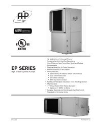
<strong>GT</strong> SERIES<br />
heat pumps<br />
O<br />
ur Geothermal units<br />
are recognized as the<br />
most efficient way to<br />
meet all your Heating<br />
and Cooling needs. Available in<br />
Vertical models from 1 to 6<br />
tons, Split models from 2 to 6<br />
tons, Horizontal models from<br />
1 to 6 tons, and Counterflow<br />
models 1 to 6 tons.<br />
Unlike air-to-air units, <strong>FHP</strong>’s<br />
<strong>GT</strong> <strong>Series</strong> utilize the earth’s<br />
ability to conserve energy.<br />
At a depth of 30 feet, ground<br />
water maintains a constant<br />
temperature within a single<br />
degree throughout the year.<br />
This temperature stability can<br />
be utilized by Well Water or<br />
Earth Coupled Geothermal<br />
(Geoexchange) systems. Even<br />
during temperature extremes<br />
our equipment maintains<br />
it’s superior efficiency and<br />
reliability.<br />
UP TO<br />
24.0<br />
EER<br />
UP TO<br />
5.7<br />
COP<br />
Environmentally Safe<br />
The Earth Coupled Systems emit no pollutants. The ground water in the Well Water<br />
System is never exposed to the atmosphere and it also causes no pollution.<br />
Real Cost Savings<br />
Savings from 50% to 70% in heating bills and up to 40% in cooling costs... Plus<br />
you can get low cost HOT WATER during the summer months with an optional<br />
recovery package.<br />
Reliability<br />
With over 30 years of experience in heat pump technology behind every <strong>FHP</strong><br />
unit, you can be sure of a quality product that will give you many years of trouble<br />
free service.<br />
ISO 9001:2000 Certified
<strong>GT</strong> SERIES<br />
VERTICAL<br />
HORIZONTAL<br />
F<br />
C<br />
D<br />
E<br />
COUNTERFLOW<br />
B<br />
A<br />
C<br />
DIMENSIONS<br />
MODEL<br />
VERTICAL / C. FLOW<br />
HORIZONTAL<br />
A B C D E F<br />
<strong>GT</strong>010 21.50 21.50 36.25 25.50 43.00 21.75<br />
<strong>GT</strong>018 21.50 21.50 40.25 25.50 45.00 21.75<br />
<strong>GT</strong>024 21.50 21.50 40.25 25.50 43.00 21.75<br />
<strong>GT</strong>030,036 21.50 26.00 47.25 26.00 54.50 21.75<br />
<strong>GT</strong>042, 048 24.00 32.75 47.25 30.00 68.00 21.75<br />
<strong>GT</strong>054, 062 26.00 33.25 51.25 30.00 68.00 21.75<br />
<strong>GT</strong>070 26.00 33.25 58.25 30.00 78.00 21.75<br />
All ratings & specifications are subject to change without notice.<br />
A<br />
B<br />
ARI / ISO 13256-1 PERFORMANCE DATA<br />
ENTERING WATER TEMPERATURES<br />
Water Loop Ground Water Ground Loop<br />
MODEL CFM 86˚F 68˚F 59˚F 50˚F 77˚F 32˚F<br />
CAPACITY AND EFFICIENCY DATA<br />
COOLING HEATING COOLING HEATING COOLING HEATING<br />
CAPACITY EER CAPACITY COP CAPACITY EER CAPACITY COP CAPACITY EER CAPACITY COP<br />
(WLHP) (WLHP) (WLHP) (WLHP) (GWHP) (GWHP) (GWHP) (GWHP) (GLHP) (GLHP) (GLHP) (GLHP)<br />
<strong>GT</strong>010 350 10,500 14.0 13,000 4.7 12,000 21.2 10,500 4.1 11,000 16.1 8,300 3.4<br />
<strong>GT</strong>018 550 15,500 16.0 16,300 5.0 17,200 24.0 13,200 4.4 16,000 18.3 10,600 3.7<br />
<strong>GT</strong>024 800 23,500 14.2 28,500 4.6 26,400 21.0 23,200 4.1 24,500 16.2 18,200 3.5<br />
<strong>GT</strong>030 1000 28,000 16.0 33,200 5.7 30,000 24.0 26,000 4.7 29,000 18.5 19,000 4.0<br />
<strong>GT</strong>036 1200 34,000 14.6 40,500 5.1 37,800 21.5 32,400 4.4 35,000 17.0 24,500 3.5<br />
<strong>GT</strong>042 1400 39,600 14.8 48,500 5.3 44,000 21.2 39,000 4.5 41,000 16.6 30,000 3.7<br />
<strong>GT</strong>048 1600 47,000 13.8 58,000 5.0 52,000 20.1 47,000 4.2 49,000 15.8 36,500 3.5<br />
<strong>GT</strong>054 1800 51,000 13.3 62,000 4.4 57,000 18.8 52,000 4.0 52,000 14.6 41,000 3.4<br />
<strong>GT</strong>062 2000 60,000 12.5 77,000 4.5 65,000 17.5 60,000 4.0 60,500 14.1 48,000 3.3<br />
<strong>GT</strong>070 2200 68,000 12.5 82,000 4.6 76,000 18.7 66,000 3.8 69,000 14.2 53,000 3.4<br />
Tabulated performance data is at noted entering water temperatures and entering air conditions of 80.6˚ F DB/66.2˚F WB<br />
at ARI/ISO 13256-1 rated CFM and copper heat exchangers.<br />
ENERGY STAR RATED<br />
<strong>FHP</strong> MANUFACTURING COMPANY<br />
601 N.W. 65TH COURT • FT. LAUDERDALE, FL 33309 • PHONE: (954) 776-5471 • FAX: (800) 776-5529<br />
http://www.fhp-mfg.com<br />
heat pumps<br />
970-146 Rev. 11/08
GUIDE<br />
SPECIFICATIONS<br />
<strong>GT</strong> <strong>Series</strong><br />
GENERAL<br />
Units shall be performance certified to ISO standard 13256-1 for Water<br />
Loop Heat Pump, Ground Water Heat Pump and Ground Loop Heat<br />
Pump applications. Units shall be Underwriter Laboratories (UL and ULc)<br />
listed for safety on all models. Each unit shall be run tested at the factory.<br />
Each unit shall be pallet mounted and stretch wrapped. The units shall<br />
be manufactured in an ISO 9001:2000 certified facility.<br />
The units shall be warranted by the manufacturer against defects in<br />
materials and workmanship for a period of one year on all parts, and 5<br />
years on the compressor.<br />
The units shall be designed to operate with entering fluid temperatures<br />
between 50 o F (10 o C) and 110 o F (43.3 o C) in cooling and temperatures<br />
between 25 o F (-3.9 o C) and 80 o F (27 o C) in heating.<br />
CASING & CABINET<br />
The cabinet shall be fabricated from heavy-gauge steel finished with<br />
Galvalume® plus, an aluminum-zinc alloy with a clear acrylic coating,<br />
for additional corrosion protection. The interior shall be insulated with<br />
½” (12.7mm) thick, multi density, coated, glass fiber. All units shall allow<br />
sufficient service access to replace the compressor without unit removal.<br />
One blower and two compressor compartment access panels shall be<br />
removable with supply and return ductwork in place. A duct collar shall<br />
be provided on the supply air opening. A filter rack with 1" (25.4mm)<br />
thick disposable filters and a 1" (25.4mm) return air duct collar shall<br />
be provided with each unit. The units shall have an insulated divider<br />
panel between the air handling section and the compressor section to<br />
minimize the transmission of compressor noise, and to permit service<br />
testing without air bypass. Units shall have a stainless steel condensate<br />
drain pan.<br />
REFRIGERATION CIRCUITS<br />
All units shall contain a sealed refrigerant circuit including a hermetic<br />
compressor, bi-directional thermal expansion valve metering device,<br />
finned tube air-to-refrigerant heat exchanger, refrigerant reversing<br />
valve and service ports. Compressor shall be high efficiency rotary or<br />
scroll type, designed for heat pump duty, quiet operation and mounted<br />
on rubber vibration isolators. Compressor motors shall be equipped<br />
with overload protection. Refrigerant reversing valves shall be pilot<br />
operated sliding piston type with replaceable encapsulated magnetic<br />
coils energized only during the cooling cycle. The finned tube coil shall<br />
be constructed of lanced aluminum fins not exceeding fourteen fins per<br />
inch bonded to rifled copper tubes in a staggered pattern not less than<br />
three rows deep and have a 450 PSIG (3100 kPa) working pressure.<br />
Coils shall have a baked polyester enamel coating for protection against<br />
most airborne chemicals. Coil end plates shall be aluminum. The<br />
coaxial water-to-refrigerant heat exchanger shall be constructed of a<br />
convoluted copper (optional cupronickel) inner tube and steel outer tube<br />
with a designed refrigerant working pressure of 450 PSIG (3100 kPa)<br />
and a designed water side working pressure of no less than 400 PSIG<br />
(2750 kPa). The water-to-refrigerant heat exchanger shall be insulated<br />
to prevent condensation at low fluid temperatures.<br />
FAN MOTOR & ASSEMBLY<br />
The fan shall be direct drive centrifugal forward curved type with a<br />
dynamically balanced wheel. The housing and wheel shall be designed<br />
for quiet low velocity operation and shall be provided with a removable<br />
inlet ring. The fan housing shall be removable from the unit without<br />
disconnecting the supply air ductwork for servicing of the fan motor.<br />
The fan motor shall be three speed PSC type for direct drive and single<br />
speed for belt drive units. The motor shall be permanently lubricated<br />
and have thermal overload protection.<br />
ELECTRICAL<br />
Controls and safety devices will be factory wired and mounted within<br />
the unit. Controls shall include fan relay, compressor contactor, 24V<br />
transformer, reversing valve coil and solid state lock-out controller (UPM).<br />
The UPM controller shall include the following features: Anti-short cycle<br />
time delay, random start, brown out/surge/power interruption protection,<br />
90 second low pressure switch bypass timer, shutdown on high or low<br />
refrigerant pressure safety switch inputs, shutdown for the optional<br />
freezestat or high level condensate sensors, 24 VAC alarm output for<br />
remote fault indication, unit reset at thermostat or disconnect, ability<br />
to defeat time delays for servicing and automatic intelligent reset. The<br />
UPM shall automatically reset after a safety shut down and restart the<br />
unit, if the cause of the shut down no longer exists, after the anti-short<br />
cycle and random start timers expire. Should a fault re-occur within 10<br />
minutes after reset, then a permanent lockout will occur. A light emitting<br />
diode (LED) shall annunciate the following alarms: high refrigerant<br />
pressure, low refrigerant pressure, low water temperature and a high<br />
level of condensate in the drain pan (when equipped with the optional<br />
low water temperature and high level condensate sensors). The LED will<br />
display each fault condition as soon as the fault occurs. If a permanent<br />
lockout occurs, then the fault LED will display the type of fault until the<br />
unit is reset.<br />
Safety devices include a low pressure cutout set a 20 PSIG (140 kPa)<br />
for loss of charge protection (freezestat and/or high discharge gas<br />
temperature sensor is not acceptable) and a high pressure cutout control<br />
set at 380 PSIG (2600 kPa). A terminal block with screw terminals shall<br />
be provided for control wiring. An optional energy management relay to<br />
allow unit control by an external source shall be factory installed.<br />
PIPING<br />
Supply, return water and condensate drain connections shall be brass<br />
female pipe thread fittings and mounted flush to cabinet exterior.<br />
INTERNAL ELECTRIC HEAT<br />
208/230-1-60 volt units shall be equipped with optional factory installed<br />
internal electric resistance heat for auxiliary and emergency heat. Electric<br />
heater must be Underwriter's Laboratories (UL and ULc) approved for<br />
safety when installed in the unit. External heater packages or heater<br />
packages not specifically listed for use with the unit are unacceptable.<br />
Electric heater packages shall include a heater collar mounted to the<br />
blower outlet, individual thermal overload protected heater elements<br />
no greater than 5kW each and magnetic contactors. Heater packages<br />
shall have a separate power supply connection from the compressor<br />
and this power supply shall also power the unit blower motor and control<br />
transformer for safe operation. Electrical heat option is not available<br />
with belt drive units.<br />
HEAT RECOVERY PACKAGE<br />
208/230 volt units shall be equipped with a optional factory installed<br />
internal heat recovery kit for domestic hot water production. This kit<br />
shall include an internally protected pump, double walled coaxial waterto-refrigerant<br />
heat exchanger, 140˚F (60˚C) hot water temperature limit<br />
switch and an on/off switch/circuit breaker.<br />
LOOP PUMP PACKAGE - CONSULT FACTORY<br />
208/230-1-60 volt units shall be equipped with an optional factory installed<br />
ground loop pump kit. This kit shall include a 1/6 HP loop pump, isolation<br />
valves and a set of purge connections for purging and pressurizing the<br />
ground loop with the unit in place. The pump, all piping and valves shall<br />
be internal to the unit.<br />
<strong>GT</strong>SPECS.INDD REV: 11-08
<strong>FHP</strong> <strong>Manufacturing</strong> Co.<br />
601 N.W. 65th Court<br />
Fort Lauderdale, FL 33309<br />
Phone: (954) 776-5471<br />
Fax: (800) 776-5529<br />
http://www.fhp-mfg.com<br />
<strong>GT</strong>/GS <strong>Series</strong> Vertical Dimensions<br />
A B C D E F G H J K M N P Q Condenser Recommended<br />
MODEL R/A Duct R/A Duct Filter Rack Water Replacement<br />
Width Depth Height Flg Width Flg Height Height Connections Nominal Filter Size<br />
<strong>GT</strong>010 21.50 21.50 36.25 9.75 11.75 5.88 5.25 5.25 8.00 14.25 17.50 14.00 16.00 4.50 3/4" F.P.T. 16 X 20 X 1<br />
<strong>GT</strong>/GS018 21.50 21.50 40.25 11.75 13.75 3.75 7.00 5.25 8.00 14.25 17.50 18.00 20.00 4.13 3/4" F.P.T. 20 X 20 X 1<br />
<strong>GT</strong>/GS024 21.50 21.50 40.25 11.75 13.75 3.75 7.00 5.25 8.00 14.25 17.50 18.00 20.00 4.13 3/4" F.P.T. 20 X 20 X 1<br />
<strong>GT</strong>/GS030, 036 21.50 26.00 47.25 13.75 15.75 6.13 5.25 5.25 8.00 15.25 22.00 22.00 24.00 4.00 3/4" F.P.T. 24 X 24 X 1<br />
<strong>GT</strong>/GS042 24.00 32.75 47.25 15.75 15.75 8.38 4.75 5.25 8.00 16.25 28.00 22.00 24.00 3.50 1" F.P.T. 24 X 30 X 1<br />
<strong>GT</strong>/GS048 24.00 32.75 47.25 15.75 15.75 8.38 5.50 5.25 8.00 16.25 28.00 22.00 24.00 4.00 1" F.P.T. 24 X 30 X 1<br />
<strong>GT</strong>/GS054 26.00 33.25 51.25 17.75 17.75 7.75 4.25 5.25 8.00 18.50 28.00 22.00 24.00 4.00 1" F.P.T. 24 X 30 X 1<br />
<strong>GT</strong>/GS062 26.00 33.25 51.25 17.75 17.75 7.13 6.25 5.25 8.00 18.50 28.00 22.00 24.00 4.00 1" F.P.T. 24 X 30 X 1<br />
<strong>GT</strong>/GS070 26.00 33.25 58.25 17.75 17.75 7.13 6.25 5.25 8.00 18.50 28.00 30.00 32.00 4.00 1" F.P.T. 16 X 30 X 1 (2)<br />
Left Hand<br />
Return<br />
(FLT)<br />
<strong>GT</strong>VTDGIP INT II.P65 REV: 3-02<br />
Right Hand<br />
Return<br />
(FRT)<br />
NOTES: All dimensions within +/- 0.125".<br />
All condensate drain connections are 3/4" FPT.<br />
All Heat Recovery Kit connections are 1/2" FPT.<br />
Internal electric heat available on 208-230/1/60 top discharge units only<br />
Internal Heat Recovery Kit available on 208-230 volt only.<br />
Specifications subject to change without notice.
<strong>FHP</strong> <strong>Manufacturing</strong> Co.<br />
601 N.W. 65th Court<br />
Fort Lauderdale, FL 33309<br />
Phone: (954) 776-5471<br />
Fax: (800) 776-5529<br />
http://www.fhp-mfg.com<br />
<strong>GT</strong>/GS <strong>Series</strong> Horizontal Dimensions<br />
A B C D E F G H J K M N P Q R T Condenser Recommended<br />
MODEL R/A Duct Filter Rack R/A Duct Water Replacement<br />
Width Depth Height Flg Width Height Flg Height Connections Nom. Filter Size<br />
<strong>GT</strong>010 25.50 43.00 21.75 2.00 17.50 23.50 5.25 14.25 7.88 9.75 0.75 11.75 5.88 0.25 20.50 18.50 3/4" F.P.T. 20 X 20 X 1<br />
<strong>GT</strong>/GS018 25.50 45.00 21.75 2.00 19.25 23.75 5.25 14.25 4.31 11.75 5.00 13.75 4.31 5.00 20.50 18.50 3/4" F.P.T. 20 X 20 X 1<br />
<strong>GT</strong>/GS024 25.50 43.00 21.75 2.00 20.00 21.00 5.25 14.25 4.31 11.75 5.00 13.75 4.31 5.00 20.50 18.50 3/4" F.P.T. 20 X 20 X 1<br />
<strong>GT</strong>/GS030,036 26.00 54.50 21.75 2.00 30.00 22.50 5.25 15.25 4.50 13.75 3.00 15.75 4.50 3.00 20.50 18.50 3/4" F.P.T. 20 X 30 X 1 (2)<br />
<strong>GT</strong>/GS042 30.00 68.00 21.75 2.50 33.50 32.00 5.25 16.25 5.81 15.75 3.00 15.75 5.81 3.00 20.50 18.50 1" F.P.T. 18 X 20 X 1 (2)<br />
<strong>GT</strong>/GS048 30.00 68.00 21.75 2.50 33.50 32.00 5.25 16.25 5.81 15.75 3.00 15.75 5.81 3.00 20.50 18.50 1" F.P.T. 18 X 20 X 1 (2)<br />
<strong>GT</strong>/GS054 30.00 68.00 21.75 2.50 33.50 32.00 5.25 18.50 4.81 17.75 2.00 17.75 4.81 2.00 20.50 18.50 1" F.P.T. 18 X 20 X 1 (2)<br />
<strong>GT</strong>/GS062 30.00 68.00 21.75 2.50 33.50 32.00 5.25 18.50 7.66 17.75 2.00 17.75 7.66 2.00 20.50 18.50 1" F.P.T. 18 X 20 X 1 (2)<br />
<strong>GT</strong>/GS070 30.00 78.00 21.75 2.50 44.00 31.50 5.25 18.50 7.66 17.75 2.00 17.75 7.66 2.00 20.50 18.50 1" F.P.T. 20 X 24 X 1 (2)<br />
Left Hand Return<br />
End Blow (FLE)<br />
Left Hand Return<br />
Straight Through (FLS)<br />
Left Hand<br />
Return<br />
Right Hand<br />
Return<br />
Right Hand Return<br />
End Blow (FRE)<br />
Right Hand Return<br />
Straight Through (FRS)<br />
NOTES: All dimensions within +/- 0.125".<br />
All condensate drain connections are 3/4" FPT.<br />
All Heat Recovery connections are 1/2" FPT.<br />
Internal electric heat available on 208-230 volt<br />
units only<br />
Internal Heat Recovery Kit available on 208-230<br />
volt units only.<br />
Units can be field converted between end blow<br />
and straight through supply air configurations.<br />
Specifications subject to change without<br />
notice.<br />
<strong>GT</strong>HZDGIP.P65 c <strong>FHP</strong> <strong>Manufacturing</strong> Company REV: 1-23-06
<strong>FHP</strong> <strong>Manufacturing</strong> Co.<br />
601 N.W. 65th Court<br />
Fort Lauderdale, FL 33309<br />
Phone: (954) 776-5471<br />
Fax: (800) 776-5529<br />
http://www.fhp-mfg.com<br />
<strong>GT</strong>/GS <strong>Series</strong> Counterflow Dimensions<br />
A B C D E F G H J K M N P Condenser Recommended<br />
MODEL Blower Blower R/A Duct R/A Duct Filter Rack Water Replacement<br />
Width Depth Height Opening Opening Flg Width Flg Height Height Connections Nominal Filter Size<br />
<strong>GT</strong>010 21.50 21.50 36.25 6.50 9.00 7.50 5.50 5.50 15.00 7.00 17.50 14.00 16.00 3/4" F.P.T. 16 X 20 X 1<br />
<strong>GT</strong>/GS018 21.50 21.50 40.25 9.25 9.63 5.00 5.13 5.50 15.00 10.13 17.50 18.00 20.00 3/4" F.P.T. 20 X 20 X 1<br />
<strong>GT</strong>/GS024 21.50 21.50 40.25 9.25 9.63 5.00 5.13 6.50 15.50 10.13 17.50 16.00 18.00 3/4" F.P.T. 20 X 20 X 1<br />
<strong>GT</strong>/GS030, 036 21.50 26.00 47.25 9.25 10.25 8.38 5.00 7.00 17.00 9.75 22.00 22.00 24.00 3/4" F.P.T. 24 X 24 X 1<br />
<strong>GT</strong>/GS042 24.00 32.75 47.25 9.25 10.25 11.63 4.50 7.50 18.50 9.25 28.00 22.00 24.00 1" F.P.T. 24 X 30 X 1<br />
<strong>GT</strong>/GS048 24.00 32.75 47.25 10.75 11.50 11.13 6.88 7.50 18.50 8.75 28.00 22.00 24.00 1" F.P.T. 24 X 30 X 1<br />
<strong>GT</strong>/GS054 26.00 33.25 51.25 10.75 11.50 11.13 6.88 7.00 20.25 9.50 28.00 22.00 24.00 1" F.P.T. 24 X 30 X 1<br />
<strong>GT</strong>/GS062 26.00 33.25 51.25 12.00 12.50 10.63 5.00 7.00 20.25 10.50 28.00 22.00 24.00 1" F.P.T. 24 X 30 X 1<br />
G/GST070 26.00 33.25 58.25 12.00 12.50 10.63 5.00 7.00 20.25 10.50 28.00 30.00 32.00 1" F.P.T. 16 X 30 X 1 (2)<br />
Left Hand<br />
Return<br />
(FLB)<br />
Right Hand<br />
Return<br />
(FRB)<br />
<strong>GT</strong>CFDGIP INT II.P65 REV: 10-06<br />
NOTES: All dimensions within +/- 0.125".<br />
All condensate drain connections are 3/4" FPT.<br />
All Heat Recovery Kit connections are 1/2" FPT.<br />
Internal electric heat available on 208-230/1/60 bottom discharge units only<br />
Internal Heat Recovery Kit available on 208-230 volt units only.<br />
Specifications subject to change without notice.
ELECTRICAL SPECIFICATIONS<br />
Electrical Elect.<br />
Characteristics Symbol<br />
Compressor Blower Loop Pump Min. Max.<br />
Circuit Fuse/<br />
RLA LRA FLA HP FLA HP Amps Breaker<br />
115-1-60 -0 8.3 44.0 2.2 1/10 - - 12.6 20<br />
208/230-1-60 -1 4.5 35.0 1.0 1/10 - - 8.4 15<br />
265-1-60 -2 3.3 23.0 0.9 1/10 - - 5.0 15<br />
BLOWER PERFORMANCE<br />
Available External Static Pressure (Inches of Water, Gauge. Wet Coil and Filter Included)<br />
Blower<br />
Speed<br />
0.10 0.20 0.30 0.40 0.50 0.60 0.70 0.80 0.90 1.00 1.10 1.20<br />
High - - - - 405 385 340 280 - - - -<br />
Medium - - - 405 385 345 290 - - - - -<br />
Low 415 410 400 380 345 300<br />
CAPACITY DATA All performance at 350 CFM and 3.0 GPM<br />
COOLING<br />
PACKAGED UNITS<br />
SPECIFICATION DATA SHEET<br />
<strong>FHP</strong> MANUFACTURING HIGH-EFFICIENCY WATER SOURCE HEAT PUMPS<br />
ISO 13256-1 CERTIFIED PERFORMANCE DATA Rated at 350 CFM and 3.0 GPM<br />
Water Loop Ground Water Ground Loo<br />
Cooling Heating Cooling Heating Cooling Heating<br />
Capacity EER Capacity COP Capacity EER Capacity COP Capacity EER Capacity COP<br />
10,500 14.0 13,000 4.7 12,000 21.2 10,500 4.1 11,000 16.1 8,300 3.4<br />
Entering Entering Sensible Heat<br />
Fluid Air Total Sensible to Power of<br />
Temp. Temp. Capacity Capacity Total Input Reject EER<br />
( o F) ( o F) (MBtuH) (MBtuH) Ratio (kW) (MBtuH)<br />
50 o<br />
60 o 70 o db<br />
70 o 61 o wb<br />
85 o<br />
100 o<br />
50 o<br />
60 o 75 o db<br />
70 o 63 o wb<br />
85 o<br />
100 o<br />
50 o<br />
60 o 80 o db<br />
70 o 67 o wb<br />
85 o<br />
100 o<br />
50 o<br />
60 o 85 o db<br />
70 o 71 o wb<br />
85 o<br />
EFT Range (Standard)<br />
45oF to 110oF<br />
10.53 6.85 0.65 0.55 12.41 19.1<br />
10.07 6.60 0.66 0.62 12.18 16.3<br />
9.61 6.37 0.66 0.68 11.94 14.0<br />
8.91 6.07 0.68 0.78 11.59 11.4<br />
8.22 5.79 0.70 0.88 11.24 9.3<br />
11.29 8.20 0.73 0.55 13.18 20.4<br />
10.79 7.90 0.73 0.62 12.91 17.4<br />
10.30 7.64 0.74 0.69 12.65 15.0<br />
9.56 7.27 0.76 0.79 12.25 12.1<br />
8.82 6.95 0.79 0.89 11.85 9.9<br />
12.40 9.06 0.73 0.56 14.30 22.2<br />
11.86 8.74 0.74 0.63 13.99 19.0<br />
11.31 8.44 0.75 0.69 13.68 16.3<br />
10.50 8.04 0.77 0.79 13.21 13.2<br />
9.69 7.68 0.79 0.90 12.75 10.8<br />
13.51 9.93 0.74 0.56 15.42 24.1<br />
12.92 9.57 0.74 0.63 15.07 20.5<br />
12.33 9.25 0.75 0.70 14.71 17.7<br />
11.44 8.81 0.77 0.80 14.17 14.3<br />
10.56 8.42 0.80 0.90 13.64 11.7<br />
HEATING<br />
<strong>GT</strong>010<br />
GEO-THERMAL<br />
MECHANICAL SPECIFICATIONS<br />
Refrigerant: R-22<br />
Air Coil<br />
Square Rows Tube Fins/<br />
Feet Deep O.D. Inch<br />
1.38 3 3/8 14<br />
Water Coil<br />
Type Work Press<br />
Coaxial 450 psig<br />
Blower Size Compr Type<br />
4x7 DD Rotary<br />
Net Weight Ship Weight<br />
152 lbs 168 lbs<br />
Fluid Pressure<br />
Flow Drop<br />
(GPM) (FOH) (PSIG)<br />
1.5 2.33 1.01<br />
2 3.90 1.69<br />
2.5 5.83 2.53<br />
3 8.10 3.51<br />
4 13.59 5.89<br />
4.2<br />
Entering Entering<br />
Heat<br />
Fluid Air Total Power of<br />
Temp. Temp. Capacity Input Abs. COP<br />
( o F) ( o F) (MBtuH) (kW) (MBtuH)<br />
50 o<br />
11.37 0.80 8.64<br />
80 o 13.51 0.91 10.39 4.3<br />
60 o<br />
12.69 0.83 9.87 4.5<br />
60<br />
70 o<br />
14.01 0.85 11.10 4.8<br />
80 o<br />
15.32 0.88 12.32 5.1<br />
50 o<br />
10.76 0.81 7.98 3.9<br />
60 o<br />
12.00 0.84 9.13 4.2<br />
70<br />
70 o<br />
13.25 0.87 10.28 4.5<br />
80 o<br />
14.49 0.89 11.44 4.8<br />
50 o<br />
10.03 0.83 7.19 3.5<br />
60 o<br />
11.19 0.86 8.26 3.8<br />
80<br />
70 o<br />
12.35 0.89 9.33 4.1<br />
100 o <strong>FHP</strong> MANUFACTURING COMPANY<br />
Units are complete packages containing a compressor, reversing valve, expansion valve metering device, and heat exchangers.<br />
Also included are safety controls: Overload protection for motors, high and low refrigerant pressure switches and a<br />
solid state lock-out circuit. Optional UL approved internal electric heater, factory installed with primary thermal overload<br />
protection and magnetic contactors (208/230-1-60 only). Optional UL approved internal Heat Recovery Package and/or<br />
Ground Loop Pump with purge connections available.<br />
Performance based on ARI/ISO rated air flow, fluid flow and voltage. For conditions other than rated, consult the <strong>FHP</strong> EAD<br />
selection software. Due to variations in installation actual performance may vary marginally from tabulated values.<br />
As a result of continuing research and development, specifications are subject to change without notice.<br />
<strong>GT</strong>010ip6 mod2 Rev: 10-06<br />
EFT Range (Standard)<br />
25 o F to 80 o F<br />
LOW TEMP HEATING<br />
25 o<br />
30 o 60 o<br />
40 o<br />
25 o<br />
30 o 70 o<br />
40 o<br />
25 o<br />
30 o 80 o<br />
40 o<br />
FLUID PRESSURE DROP<br />
Antifreeze Required<br />
7.92 0.74 5.41 3.2<br />
8.57 0.75 6.01 3.4<br />
9.86 0.77 7.21 3.7<br />
7.50 0.75 4.94 2.9<br />
8.11 0.76 5.51 3.1<br />
9.33 0.79 6.64 3.5<br />
7.00 0.76 4.39 2.7<br />
7.57 0.78 4.91 2.9<br />
8.70 0.81 5.95 3.2<br />
601 N.W. 65th Court - Fort Lauderdale, FL 33309<br />
Phone: (954) 776-5471 - Fax: (800) 776-5529<br />
http://www.fhp-mfg.com
ELECTRICAL SPECIFICATIONS<br />
Electrical Elect.<br />
Characteristics Symbol<br />
Compressor Blower Loop Pump Min. Max.<br />
Circuit Fuse/<br />
RLA LRA FLA HP FLA HP Amps Breaker<br />
208/230-1-60 -1 5.9 29.0 1.8 1/4 - - 11.0 15<br />
265-1-60 -2 5.5 27.0 1.6 1/4 - - 8.5 15<br />
BLOWER PERFORMANCE<br />
Available External Static Pressure (Inches of Water, Gauge. Wet Coil and Filter Included)<br />
Blower<br />
Speed<br />
0.10 0.20 0.30 0.40 0.50 0.60 0.70 0.80 0.90 1.00 1.10 1.20<br />
High - - - 750 720 640 510 460 - - - -<br />
Medium - - 750 720 650 530 480 - - - - -<br />
Low 760 730 670 555 490 420 - - - - - -<br />
CAPACITY DATA All performance at 550 CFM and 4.0 GPM<br />
COOLING<br />
PACKAGED UNITS<br />
SPECIFICATION DATA SHEET<br />
<strong>FHP</strong> MANUFACTURING HIGH-EFFICIENCY WATER SOURCE HEAT PUMPS<br />
ISO 13256-1 CERTIFIED PERFORMANCE DATA Rated at 550 CFM and 4.0 GPM<br />
Water Loop Ground Water Ground Loop<br />
Cooling Heating Cooling Heating Cooling Heating<br />
Capacity EER Capacity COP Capacity EER Capacity COP Capacity EER Capacity COP<br />
15,500 16.0 16,300 5.0 17,200 24.0 13,200 4.4 16,000 18.3 10,600 3.7<br />
Entering Entering Sensible Heat<br />
Fluid Air Total Sensible to Power of<br />
Temp. Temp. Capacity Capacity Total Input Reject EER<br />
( o F) ( o F) (MBtuH) (MBtuH) Ratio (kW) (MBtuH)<br />
50 o<br />
60 o 70 o db<br />
70 o 61 o wb<br />
85 o<br />
100 o<br />
50 o<br />
60 o 75 o db<br />
70 o 63 o wb<br />
85 o<br />
100 o<br />
50 o<br />
60 o 80 o db<br />
70 o 67 o wb<br />
85 o<br />
100 o<br />
50 o<br />
60 o 85 o db<br />
70 o 71 o wb<br />
85 o<br />
EFT Range (Standard)<br />
45 o F to 110 o F<br />
14.85 9.62 0.65 0.74 17.38 20.1<br />
14.33 9.35 0.65 0.83 17.16 17.2<br />
13.80 9.12 0.66 0.92 16.95 15.0<br />
13.02 8.83 0.68 1.06 16.63 12.3<br />
12.23 8.59 0.70 1.20 16.32 10.2<br />
15.93 11.54 0.72 0.74 18.47 21.4<br />
15.37 11.23 0.73 0.84 18.22 18.4<br />
14.81 10.95 0.74 0.93 17.97 16.0<br />
13.97 10.61 0.76 1.06 17.60 13.1<br />
13.13 10.32 0.79 1.20 17.23 10.9<br />
17.50 12.76 0.73 0.75 20.06 23.4<br />
16.89 12.42 0.74 0.84 19.76 20.1<br />
16.28 12.12 0.74 0.93 19.46 17.4<br />
15.35 11.73 0.76 1.07 19.01 14.3<br />
14.43 11.42 0.79 1.21 18.57 11.9<br />
19.08 14.00 0.73 0.75 21.65 25.3<br />
18.41 13.62 0.74 0.85 21.30 21.7<br />
17.74 13.29 0.75 0.94 20.95 18.9<br />
16.74 12.87 0.77 1.08 20.43 15.5<br />
15.74 12.53 0.80 1.22 19.90 12.9<br />
HEATING<br />
<strong>GT</strong>018<br />
GEO-THERMAL<br />
MECHANICAL SPECIFICATIONS<br />
Refrigerant: R-22<br />
Air Coil<br />
Square Rows Tube Fins/<br />
Feet Deep O.D. Inch<br />
2.3 3 3/8 14<br />
Water Coil<br />
Type Work Press<br />
Coaxial 450 psig<br />
Blower Size Compr Type<br />
9x7 DD Rotary<br />
Net Weight Ship Weight<br />
170 lbs 181 lbs<br />
Fluid Pressure<br />
Flow Drop<br />
(GPM) (FOH) (PSIG)<br />
2 1.35 0.58<br />
3 2.80 1.21<br />
4 4.70 2.03<br />
5 7.02 3.04<br />
6 9.75 4.22<br />
4.3<br />
Entering Entering<br />
Heat<br />
Fluid Air Total Power of<br />
Temp. Temp. Capacity Input Abs. COP<br />
( o F) ( o F) (MBtuH) (kW) (MBtuH)<br />
50 o<br />
14.49 1.00 11.09<br />
80 o 17.01 1.13 13.15 4.4<br />
60 o<br />
16.08 1.03 12.58 4.6<br />
60<br />
70 o<br />
17.68 1.06 14.06 4.9<br />
80 o<br />
19.27 1.09 15.55 5.2<br />
50 o<br />
13.71 1.01 10.26 4.0<br />
60 o<br />
15.22 1.04 11.65 4.3<br />
70<br />
70 o<br />
16.72 1.08 13.05 4.6<br />
80 o<br />
18.23 1.11 14.45 4.8<br />
50 o<br />
12.80 1.03 9.28 3.6<br />
60 o<br />
14.20 1.07 10.57 3.9<br />
80<br />
70 o<br />
15.60 1.10 11.86 4.2<br />
100 o <strong>FHP</strong> MANUFACTURING COMPANY<br />
Units are complete packages containing a compressor, reversing valve, expansion valve metering device, and heat exchangers.<br />
Also included are safety controls: Overload protection for motors, high and low refrigerant pressure switches and a<br />
solid state lock-out circuit. Optional UL approved internal electric heater, factory installed with primary thermal overload<br />
protection and magnetic contactors (208/230-1-60 only). Optional UL approved internal Heat Recovery Package and/or<br />
Ground Loop Pump with purge connections available.<br />
Performance based on ARI/ISO rated air flow, fluid flow and voltage. For conditions other than rated, consult the <strong>FHP</strong> EAD<br />
selection software. Due to variations in installation actual performance may vary marginally from tabulated values.<br />
As a result of continuing research and development, specifications are subject to change without notice.<br />
<strong>GT</strong>018ip6 mod2 Rev: 10-06<br />
EFT Range (Standard)<br />
25 o F to 80 o F<br />
LOW TEMP HEATING<br />
25 o<br />
30 o 60 o<br />
40 o<br />
25 o<br />
30 o 70 o<br />
40 o<br />
25 o<br />
30 o 80 o<br />
40 o<br />
FLUID PRESSURE DROP<br />
Antifreeze Required<br />
10.30 0.92 7.17 3.3<br />
11.08 0.93 7.90 3.5<br />
12.64 0.96 9.35 3.8<br />
9.75 0.93 6.57 3.1<br />
10.49 0.95 7.26 3.2<br />
11.97 0.98 8.62 3.6<br />
9.11 0.95 5.87 2.8<br />
9.80 0.97 6.50 3.0<br />
11.18 1.00 7.76 3.3<br />
601 N.W. 65th Court - Fort Lauderdale, FL 33309<br />
Phone: (954) 776-5471 - Fax: (800) 776-5529<br />
http://www.fhp-mfg.com
ELECTRICAL SPECIFICATIONS<br />
Electrical Elect. Compressor Blower Loop Pump Min. Max.<br />
Characteristics Symbol<br />
Circuit Fuse/<br />
RLA LRA FLA HP FLA HP Amps Breaker<br />
208/230-1-60 -1 10.3 56.0 1.8 1/4 - - 16.5 20<br />
265-1-60 -2 8.7 47.0 1.6 1/4 - - 12.5 15<br />
208/230-3-60 -3 7.1 45.0 1.8 1/4 - - 10.7 15<br />
460-3-60 -4 3.5 22.4 0.9 1/4 - - 5.3 15<br />
BLOWER PERFORMANCE<br />
Available External Static Pressure (Inches of Water, Gauge. Wet Coil and Filter Included)<br />
Blower<br />
0.10 0.20 0.30 0.40 0.50 0.60 0.70 0.80 0.90 1.00 1.10 1.20<br />
Speed<br />
High 900 850 800 760 710 690 680 670 - - - -<br />
Medium 750 720 690 670 - - - - - - - -<br />
Low 670 - - - - - - - - - - -<br />
CAPACITY DATA All performance at 800 CFM and 5.0 GPM<br />
COOLING<br />
PACKAGED UNITS<br />
SPECIFICATION DATA SHEET<br />
<strong>FHP</strong> MANUFACTURING HIGH-EFFICIENCY WATER SOURCE HEAT PUMPS<br />
ISO 13256-1 CERTIFIED PERFORMANCE DATA Rated at 800 CFM and 5.0 GPM<br />
Water Loop Ground Water Ground Loop<br />
Cooling Heating Cooling Heating Cooling Heating<br />
Capacity EER Capacity COP Capacity EER Capacity COP Capacity EER Capacity COP<br />
23,500 14.2 28,500 4.6 26,400 21.0 23,200 4.1 24,500 16.2 18,200 3.5<br />
Entering Entering Sensible Heat<br />
Fluid Air Total Sensible to Power of<br />
Temp. Temp. Capacity Capacity Total Input Reject EER<br />
( o F) ( o F) (MBtuH) (MBtuH) Ratio (kW) (MBtuH)<br />
50 o<br />
60 o 70 o db<br />
70 o 61 o wb<br />
85 o<br />
100 o<br />
50 o<br />
60 o 75 o db<br />
70 o 63 o wb<br />
85 o<br />
100 o<br />
50 o<br />
60 o 80 o db<br />
70 o 67 o wb<br />
85 o<br />
100 o<br />
50 o<br />
60 o 85 o db<br />
70 o 71 o wb<br />
85 o<br />
EFT Range (Standard)<br />
45 o F to 110 o F<br />
23.25 15.18 0.65 1.19 27.32 19.5<br />
22.36 14.72 0.66 1.34 26.93 16.7<br />
21.48 14.32 0.67 1.48 26.53 14.5<br />
20.15 13.78 0.68 1.70 25.94 11.9<br />
18.82 13.32 0.71 1.91 25.35 9.8<br />
24.91 18.15 0.73 1.20 29.00 20.8<br />
23.96 17.60 0.73 1.34 28.55 17.8<br />
23.01 17.11 0.74 1.49 28.10 15.5<br />
21.59 16.48 0.76 1.71 27.42 12.7<br />
20.16 15.93 0.79 1.93 26.74 10.7<br />
27.34 20.03 0.73 1.21 31.46 22.6<br />
26.30 19.43 0.74 1.35 30.92 19.4<br />
25.26 18.89 0.75 1.50 30.38 16.8<br />
23.70 18.19 0.77 1.72 29.57 13.8<br />
22.14 17.59 0.79 1.94 28.76 11.4<br />
29.77 21.93 0.74 1.22 33.92 24.5<br />
28.64 21.28 0.74 1.36 33.29 21.0<br />
27.50 20.69 0.75 1.51 32.67 18.2<br />
25.81 19.93 0.77 1.73 31.73 14.9<br />
24.11 19.27 0.80 1.96 30.78 12.3<br />
HEATING<br />
<strong>GT</strong>024<br />
GEO-THERMAL<br />
MECHANICAL SPECIFICATIONS<br />
Refrigerant: R-22<br />
Air Coil<br />
Square Rows Tube Fins/<br />
Feet Deep O.D. Inch<br />
2.12 3 3/8 14<br />
Water Coil<br />
Type Work Press<br />
Coaxial 450 psig<br />
Blower Size Compr Type<br />
9x7 DD Scroll<br />
Net Weight Ship Weight<br />
174 lbs 185 lbs<br />
Fluid Pressure<br />
Flow Drop<br />
(GPM) (FOH) (PSIG)<br />
3 1.26 0.55<br />
5 3.17 1.37<br />
6 4.40 1.90<br />
8 7.38 3.20<br />
10 11.04 4.78<br />
4.2<br />
Entering Entering<br />
Heat<br />
Fluid Air Total Power of<br />
Temp. Temp. Capacity Input Abs. COP<br />
( o F) ( o F) (MBtuH) (kW) (MBtuH)<br />
50 o<br />
24.81 1.72 18.92<br />
80 o 29.48 2.04 22.50 4.2<br />
60 o<br />
27.69 1.80 21.53 4.5<br />
60<br />
70 o<br />
30.58 1.88 24.14 4.8<br />
80 o<br />
33.46 1.96 26.76 5.0<br />
50 o<br />
23.45 1.76 17.46 3.9<br />
60 o<br />
26.18 1.84 19.91 4.2<br />
70<br />
70 o<br />
28.90 1.92 22.36 4.4<br />
80 o<br />
31.63 2.00 24.80 4.6<br />
50 o<br />
21.86 1.80 15.74 3.6<br />
60 o<br />
24.40 1.88 17.99 3.8<br />
80<br />
70 o<br />
26.94 1.96 20.25 4.0<br />
100 o <strong>FHP</strong> MANUFACTURING COMPANY<br />
Units are complete packages containing a compressor, reversing valve, expansion valve metering device, and heat exchangers.<br />
Also included are safety controls: Overload protection for motors, high and low refrigerant pressure switches and a<br />
solid state lock-out circuit. Optional UL approved internal electric heater, factory installed with primary thermal overload<br />
protection and magnetic contactors (208/230-1-60 only). Optional UL approved internal Heat Recovery Package and/or<br />
Ground Loop Pump with purge connections available.<br />
Performance based on ARI/ISO rated air flow, fluid flow and voltage. For conditions other than rated, consult the <strong>FHP</strong> EAD<br />
selection software. Due to variations in installation actual performance may vary marginally from tabulated values.<br />
As a result of continuing research and development, specifications are subject to change without notice.<br />
<strong>GT</strong>024ip6 mod2 Rev: 10-06<br />
EFT Range (Standard)<br />
25 o F to 80 o F<br />
LOW TEMP HEATING<br />
25 o<br />
30 o 60 o<br />
40 o<br />
25 o<br />
30 o 70 o<br />
40 o<br />
25 o<br />
30 o 80 o<br />
40 o<br />
FLUID PRESSURE DROP<br />
Antifreeze Required<br />
17.25 1.53 12.04 3.3<br />
18.66 1.57 13.32 3.5<br />
21.49 1.65 15.88 3.8<br />
16.31 1.55 11.01 3.1<br />
17.65 1.59 12.21 3.2<br />
20.32 1.68 14.60 3.6<br />
15.21 1.59 9.80 2.8<br />
16.46 1.63 10.90 3.0<br />
18.95 1.71 13.10 3.2<br />
601 N.W. 65th Court - Fort Lauderdale, FL 33309<br />
Phone: (954) 776-5471 - Fax: (800) 776-5529<br />
http://www.fhp-mfg.com
ELECTRICAL SPECIFICATIONS<br />
Electrical Elect. Compressor Blower Loop Pump Min. Max.<br />
Characteristics Symbol<br />
Circuit Fuse/<br />
RLA LRA FLA HP FLA HP Amps Breaker<br />
208/230-1-60 -1 10.3 56.0 1.80 1/4 - - 16.5 20<br />
265-1-60 -2 8.7 47.0 1.60 1/4 - - 12.5 15<br />
208/230-3-60 -3 7.1 45.0 1.80 1/4 - - 10.7 15<br />
460-3-60 -4 3.5 22.4 0.90 1/4 - - 5.3 15<br />
BLOWER PERFORMANCE<br />
Available External Static Pressure (Inches of Water, Gauge. Wet Coil and Filter Included)<br />
Blower<br />
0.10 0.20 0.30 0.40 0.50 0.60 0.70 0.80 0.90 1.00 1.10 1.20<br />
Speed<br />
High 1275 1210 1140 1060 980 900 820 720 - - - -<br />
Medium 1040 1010 970 920 860 790 730 - - - - -<br />
Low 950 930 900 860 810 750 - - - - - -<br />
CAPACITY DATA All performance at 1,000 CFM and 7.5 GPM<br />
COOLING<br />
PACKAGED UNITS<br />
SPECIFICATION DATA SHEET<br />
<strong>FHP</strong> MANUFACTURING HIGH-EFFICIENCY WATER SOURCE HEAT PUMPS<br />
ISO 13256-1 CERTIFIED PERFORMANCE DATA Rated at 1,000 CFM and 7.5 GPM<br />
Water Loop Ground Water Ground Loop<br />
Cooling Heating Cooling Heating Cooling Heating<br />
Capacity EER Capacity COP Capacity EER Capacity COP Capacity EER Capacity COP<br />
28,000 16.0 33,200 5.7 30,000 24.0 26,000 4.7 29,000 18.5 19,000 4.0<br />
Entering Entering Sensible Heat<br />
Fluid Air Total Sensible to Power of<br />
Temp. Temp. Capacity Capacity Total Input Reject EER<br />
( o F) ( o F) (MBtuH) (MBtuH) Ratio (kW) (MBtuH)<br />
50 o<br />
60 o 70 o db<br />
70 o 61 o wb<br />
85 o<br />
100 o<br />
50 o<br />
60 o 75 o db<br />
70 o 63 o wb<br />
85 o<br />
100 o<br />
50 o<br />
60 o 80 o db<br />
70 o 67 o wb<br />
85 o<br />
100 o<br />
50 o<br />
60 o 85 o db<br />
70 o 71 o wb<br />
85 o<br />
EFT Range (Standard)<br />
45 o F to 110 o F<br />
26.12 17.28 0.66 1.13 29.99 23.0<br />
25.55 17.04 0.67 1.32 30.04 19.4<br />
24.97 16.87 0.68 1.50 30.08 16.7<br />
24.11 16.72 0.69 1.77 30.15 13.6<br />
23.25 16.68 0.72 2.04 30.22 11.4<br />
27.98 20.64 0.74 1.14 31.88 24.5<br />
27.37 20.36 0.74 1.32 31.88 20.7<br />
26.76 20.15 0.75 1.51 31.89 17.8<br />
25.83 19.98 0.77 1.78 31.91 14.5<br />
24.91 19.94 0.80 2.05 31.92 12.1<br />
30.71 22.78 0.74 1.15 34.63 26.7<br />
30.04 22.47 0.75 1.33 34.59 22.5<br />
29.36 22.25 0.76 1.52 34.54 19.4<br />
28.35 22.05 0.78 1.79 34.47 15.8<br />
27.34 22.01 0.80 2.07 34.40 13.2<br />
33.44 24.95 0.75 1.16 37.39 28.9<br />
32.70 24.61 0.75 1.34 37.29 24.3<br />
31.97 24.36 0.76 1.53 37.19 20.9<br />
30.87 24.14 0.78 1.81 37.04 17.1<br />
29.77 24.10 0.81 2.09 36.89 14.3<br />
HEATING<br />
<strong>GT</strong>030<br />
GEO-THERMAL<br />
MECHANICAL SPECIFICATIONS<br />
Refrigerant: R-22<br />
Air Coil<br />
Square Rows Tube Fins/<br />
Feet Deep O.D. Inch<br />
3.50 3 3/8 14<br />
Water Coil<br />
Type Work Press<br />
Coaxial 450 psig<br />
Blower Size Compr Type<br />
9x7 DD Scroll<br />
Net Weight Ship Weight<br />
231 lbs 251 lbs<br />
Fluid Pressure<br />
Flow Drop<br />
(GPM) (FOH) (PSIG)<br />
4 2.07 0.90<br />
6 4.29 1.86<br />
8 7.20 3.12<br />
10 10.76 4.66<br />
12 14.94 6.47<br />
5.0<br />
Entering Entering<br />
Heat<br />
Fluid Air Total Power of<br />
Temp. Temp. Capacity Input Abs. COP<br />
( o F) ( o F) (MBtuH) (kW) (MBtuH)<br />
50 o<br />
27.72 1.62 22.20<br />
80 o 35.02 1.95 28.36 5.3<br />
60 o<br />
31.73 1.70 25.91 5.5<br />
60<br />
70 o<br />
35.74 1.79 29.63 5.9<br />
80 o<br />
39.76 1.88 33.35 6.2<br />
50 o<br />
26.20 1.65 20.58 4.7<br />
60 o<br />
29.99 1.73 24.07 5.1<br />
70<br />
70 o<br />
33.79 1.82 27.57 5.4<br />
80 o<br />
37.58 1.91 31.06 5.8<br />
50 o<br />
24.43 1.68 18.68 4.3<br />
60 o<br />
27.96 1.77 21.91 4.6<br />
80<br />
70 o<br />
31.49 1.86 25.13 5.0<br />
100 o <strong>FHP</strong> MANUFACTURING COMPANY<br />
Units are complete packages containing a compressor, reversing valve, expansion valve metering device, and heat exchangers.<br />
Also included are safety controls: Overload protection for motors, high and low refrigerant pressure switches and a<br />
solid state lock-out circuit. Optional UL approved internal electric heater, factory installed with primary thermal overload<br />
protection and magnetic contactors (208/230-1-60 only). Optional UL approved internal Heat Recovery Package and/or<br />
Ground Loop Pump with purge connections available.<br />
Performance based on ARI/ISO rated air flow, fluid flow and voltage. For conditions other than rated, consult the <strong>FHP</strong> EAD<br />
selection software. Due to variations in installation actual performance may vary marginally from tabulated values.<br />
As a result of continuing research and development, specifications are subject to change without notice.<br />
<strong>GT</strong>030ip6 mod2 Rev: 10-06<br />
EFT Range (Standard)<br />
25 o F to 80 o F<br />
LOW TEMP HEATING<br />
25 o<br />
30 o 60 o<br />
40 o<br />
25 o<br />
30 o 70 o<br />
40 o<br />
25 o<br />
30 o 80 o<br />
40 o<br />
FLUID PRESSURE DROP<br />
Antifreeze Required<br />
17.34 1.40 12.55 3.6<br />
19.30 1.45 14.37 3.9<br />
23.24 1.53 18.01 4.4<br />
16.40 1.43 11.53 3.4<br />
18.26 1.47 13.23 3.6<br />
21.97 1.56 16.65 4.1<br />
15.29 1.46 10.32 3.1<br />
17.02 1.50 11.89 3.3<br />
20.49 1.59 15.05 3.8<br />
601 N.W. 65th Court - Fort Lauderdale, FL 33309<br />
Phone: (954) 776-5471 - Fax: (800) 776-5529<br />
http://www.fhp-mfg.com
ELECTRICAL SPECIFICATIONS<br />
Electrical Elect. Compressor Blower Loop Pump Min. Max.<br />
Characteristics Symbol<br />
Circuit Fuse/<br />
RLA LRA FLA HP FLA HP Amps Breaker<br />
208/230-1-60 -1 13.5 72.5 3.90 1/2 - - 22.5 30<br />
265-1-60 -2 11.5 61.0 2.30 1/2 - - 16.7 25<br />
208/230-3-60 -3 9.0 63.0 3.90 1/2 - - 15.2 20<br />
460-3-60 -4 4.5 31.0 2.00 1/2 - - 7.6 15<br />
BLOWER PERFORMANCE<br />
Available External Static Pressure (Inches of Water, Gauge. Wet Coil and Filter Included)<br />
Blower<br />
0.10 0.20 0.30 0.40 0.50 0.60 0.70 0.80 0.90 1.00 1.10 1.20<br />
Speed<br />
High 1500 1440 1370 1290 1210 1120 1020 900 - - - -<br />
Medium 1410 1350 1290 1220 1150 1060 960 - - - - -<br />
Low 1290 1250 1200 1150 1080 1000 - - - - - -<br />
CAPACITY DATA All performance at 1,200 CFM and 9.0 GPM<br />
COOLING<br />
PACKAGED UNITS<br />
SPECIFICATION DATA SHEET<br />
<strong>FHP</strong> MANUFACTURING HIGH-EFFICIENCY WATER SOURCE HEAT PUMPS<br />
ISO 13256-1 CERTIFIED PERFORMANCE DATA Rated at 1,000 CFM and 7.5 GPM<br />
Water Loop Ground Water Ground Loop<br />
Cooling Heating Cooling Heating Cooling Heating<br />
Capacity EER Capacity COP Capacity EER Capacity COP Capacity EER Capacity COP<br />
34,000 14.6 40,500 5.1 37,800 21.5 32,400 4.4 35,000 17.0 24,500 3.5<br />
Entering Entering Sensible Heat<br />
Fluid Air Total Sensible to Power of<br />
Temp. Temp. Capacity Capacity Total Input Reject EER<br />
( o F) ( o F) (MBtuH) (MBtuH) Ratio (kW) (MBtuH)<br />
50 o<br />
60 o 70 o db<br />
70 o 61 o wb<br />
85 o<br />
100 o<br />
50 o<br />
60 o 75 o db<br />
70 o 63 o wb<br />
85 o<br />
100 o<br />
50 o<br />
60 o 80 o db<br />
70 o 67 o wb<br />
85 o<br />
100 o<br />
50 o<br />
60 o 85 o db<br />
70 o 71 o wb<br />
85 o<br />
EFT Range (Standard)<br />
45 o F to 110 o F<br />
33.13 21.89 0.66 1.63 38.68 20.4<br />
31.95 21.29 0.67 1.83 38.19 17.5<br />
30.77 20.76 0.67 2.03 37.70 15.1<br />
29.00 20.08 0.69 2.33 36.97 12.4<br />
27.23 19.52 0.72 2.64 36.24 10.3<br />
35.50 26.17 0.74 1.64 41.08 21.7<br />
34.23 25.45 0.74 1.84 40.51 18.6<br />
32.97 24.82 0.75 2.04 39.94 16.1<br />
31.08 24.01 0.77 2.35 39.09 13.2<br />
29.19 23.34 0.80 2.65 38.24 11.0<br />
38.96 28.89 0.74 1.65 44.59 23.6<br />
37.58 28.10 0.75 1.85 43.90 20.3<br />
36.19 27.40 0.76 2.06 43.22 17.6<br />
34.12 26.51 0.78 2.37 42.19 14.4<br />
32.04 25.77 0.80 2.67 41.17 12.0<br />
42.42 31.64 0.75 1.66 48.09 25.5<br />
40.92 30.77 0.75 1.87 47.29 21.9<br />
39.41 30.01 0.76 2.07 46.49 19.0<br />
37.15 29.04 0.78 2.38 45.29 15.6<br />
34.90 28.23 0.81 2.70 44.09 12.9<br />
HEATING<br />
<strong>GT</strong>036<br />
GEO-THERMAL<br />
MECHANICAL SPECIFICATIONS<br />
Refrigerant: R-22<br />
Air Coil<br />
Square Rows Tube Fins/<br />
Feet Deep O.D. Inch<br />
3.50 3 3/8 14<br />
Water Coil<br />
Type Work Press<br />
Coaxial 450 psig<br />
Blower Size Compr Type<br />
9x7 DD Scroll<br />
Net Weight Ship Weight<br />
243 lbs 263 lbs<br />
Fluid Pressure<br />
Flow Drop<br />
(GPM) (FOH) (PSIG)<br />
5 3.05 1.32<br />
7 5.60 2.42<br />
9 8.80 3.81<br />
11 12.63 5.47<br />
13 17.06 7.38<br />
4.5<br />
Entering Entering<br />
Heat<br />
Fluid Air Total Power of<br />
Temp. Temp. Capacity Input Abs. COP<br />
( o F) ( o F) (MBtuH) (kW) (MBtuH)<br />
50 o<br />
34.59 2.24 26.95<br />
80 o 42.38 2.56 33.63 4.8<br />
60 o<br />
39.10 2.31 31.20 5.0<br />
60<br />
70 o<br />
43.60 2.39 35.45 5.3<br />
80 o<br />
48.10 2.46 39.69 5.7<br />
50 o<br />
32.71 2.28 24.93 4.2<br />
60 o<br />
36.96 2.36 28.92 4.6<br />
70<br />
70 o<br />
41.22 2.43 32.92 5.0<br />
80 o<br />
45.47 2.51 36.91 5.3<br />
50 o<br />
30.49 2.33 22.55 3.8<br />
60 o<br />
34.46 2.41 26.24 4.2<br />
80<br />
70 o<br />
38.42 2.49 29.94 4.5<br />
100 o <strong>FHP</strong> MANUFACTURING COMPANY<br />
Units are complete packages containing a compressor, reversing valve, expansion valve metering device, and heat exchangers.<br />
Also included are safety controls: Overload protection for motors, high and low refrigerant pressure switches and a<br />
solid state lock-out circuit. Optional UL approved internal electric heater, factory installed with primary thermal overload<br />
protection and magnetic contactors (208/230-1-60 only). Optional UL approved internal Heat Recovery Package and/or<br />
Ground Loop Pump with purge connections available.<br />
Performance based on ARI/ISO rated air flow, fluid flow and voltage. For conditions other than rated, consult the <strong>FHP</strong> EAD<br />
selection software. Due to variations in installation actual performance may vary marginally from tabulated values.<br />
As a result of continuing research and development, specifications are subject to change without notice.<br />
<strong>GT</strong>036ip6 mod2 Rev: 10-06<br />
EFT Range (Standard)<br />
25 o F to 80 o F<br />
LOW TEMP HEATING<br />
25 o<br />
30 o 60 o<br />
40 o<br />
25 o<br />
30 o 70 o<br />
40 o<br />
25 o<br />
30 o 80 o<br />
40 o<br />
FLUID PRESSURE DROP<br />
Antifreeze Required<br />
22.88 2.05 15.88 3.3<br />
25.08 2.09 17.96 3.5<br />
29.50 2.16 22.12 4.0<br />
21.64 2.09 14.52 3.0<br />
23.72 2.12 16.47 3.3<br />
27.89 2.20 20.38 3.7<br />
20.18 2.13 12.91 2.8<br />
22.13 2.17 14.72 3.0<br />
26.01 2.25 18.33 3.4<br />
601 N.W. 65th Court - Fort Lauderdale, FL 33309<br />
Phone: (954) 776-5471 - Fax: (800) 776-5529<br />
http://www.fhp-mfg.com
ELECTRICAL SPECIFICATIONS<br />
Electrical Elect. Compressor Blower Loop Pump Min. Max.<br />
Characteristics Symbol<br />
Circuit Fuse/<br />
RLA LRA FLA HP FLA HP Amps Breaker<br />
208/230-1-60 -1 16.0 88.0 3.9 1/2 - - 25.7 35<br />
265-1-60 -2 12.8 75.0 2.3 1/2 - - 18.3 30<br />
208/230-3-60 -3 10.3 77.0 3.9 1/2 - - 16.8 25<br />
460-3-60 -4 5.1 39.0 2.0 1/2 - - 8.4 15<br />
BLOWER PERFORMANCE<br />
Available External Static Pressure (Inches of Water, Gauge. Wet Coil and Filter Included)<br />
Blower<br />
0.10 0.20 0.30 0.40 0.50 0.60 0.70 0.80 0.90 1.00 1.10 1.20<br />
Speed<br />
High - 1570 1500 1420 1330 1260 1190 1100 - - - -<br />
Medium 1560 1520 1450 1380 1290 1140 1000 - - - - -<br />
Low 1380 1290 1200 1090 980 - - - - - - -<br />
CAPACITY DATA All performance at 1,400 CFM and 9.0 GPM<br />
COOLING<br />
PACKAGED UNITS<br />
SPECIFICATION DATA SHEET<br />
<strong>FHP</strong> MANUFACTURING HIGH-EFFICIENCY WATER SOURCE HEAT PUMPS<br />
ISO 13256-1 CERTIFIED PERFORMANCE DATA Rated at 1,400 CFM and 9.0 GPM<br />
Water Loop Ground Water Ground Loop<br />
Cooling Heating Cooling Heating Cooling Heating<br />
Capacity EER Capacity COP Capacity EER Capacity COP Capacity EER Capacity COP<br />
39,600 14.8 48,500 5.3 44,000 21.2 39,000 4.5 41,000 16.6 30,000 3.7<br />
Entering Entering Sensible Heat<br />
Fluid Air Total Sensible to Power of<br />
Temp. Temp. Capacity Capacity Total Input Reject EER<br />
( o F) ( o F) (MBtuH) (MBtuH) Ratio (kW) (MBtuH)<br />
50 o<br />
60 o 70 o db<br />
70 o 61 o wb<br />
85 o<br />
100 o<br />
50 o<br />
60 o 75 o db<br />
70 o 63 o wb<br />
85 o<br />
100 o<br />
50 o<br />
60 o 80 o db<br />
70 o 67 o wb<br />
85 o<br />
100 o<br />
50 o<br />
60 o 85 o db<br />
70 o 71 o wb<br />
85 o<br />
EFT Range (Standard)<br />
45 o F to 110 o F<br />
38.40 25.31 0.66 2.04 45.35 18.9<br />
37.05 24.62 0.66 2.26 44.75 16.4<br />
35.70 24.02 0.67 2.47 44.15 14.4<br />
33.68 23.26 0.69 2.80 43.24 12.0<br />
31.66 22.63 0.71 3.13 42.34 10.1<br />
41.16 30.29 0.74 2.05 48.14 20.1<br />
39.71 29.48 0.74 2.27 47.45 17.5<br />
38.27 28.76 0.75 2.49 46.76 15.4<br />
36.10 27.85 0.77 2.82 45.72 12.8<br />
33.94 27.11 0.80 3.15 44.68 10.8<br />
45.19 33.46 0.74 2.06 52.23 21.9<br />
43.61 32.56 0.75 2.28 51.40 19.1<br />
42.03 31.77 0.76 2.51 50.58 16.8<br />
39.65 30.78 0.78 2.84 49.34 14.0<br />
37.28 29.95 0.80 3.17 48.11 11.8<br />
49.22 36.66 0.74 2.08 56.32 23.7<br />
47.50 35.68 0.75 2.30 55.36 20.6<br />
45.78 34.82 0.76 2.53 54.40 18.1<br />
43.20 33.72 0.78 2.86 52.96 15.1<br />
40.62 32.82 0.81 3.20 51.53 12.7<br />
HEATING<br />
<strong>GT</strong>042<br />
GEO-THERMAL<br />
MECHANICAL SPECIFICATIONS<br />
Refrigerant: R-22<br />
Air Coil<br />
Square Rows Tube Fins/<br />
Feet Deep O.D. Inch<br />
4.50 3 3/8 14<br />
Water Coil<br />
Type Work Press<br />
Coaxial 450 psig<br />
Blower Size Compr Type<br />
9x7 DD Scroll<br />
Net Weight Ship Weight<br />
260 lbs 280 lbs<br />
Fluid Pressure<br />
Flow Drop<br />
(GPM) (FOH) (PSIG)<br />
5 1.98 0.86<br />
7 3.63 1.57<br />
9 5.70 2.47<br />
13 11.05 4.78<br />
15 14.30 6.19<br />
4.6<br />
Entering Entering<br />
Heat<br />
Fluid Air Total Power of<br />
Temp. Temp. Capacity Input Abs. COP<br />
( o F) ( o F) (MBtuH) (kW) (MBtuH)<br />
50 o<br />
41.90 2.68 32.75<br />
80 o 50.68 3.05 40.27 4.9<br />
60 o<br />
47.10 2.77 37.66 5.0<br />
60<br />
70 o<br />
52.30 2.85 42.58 5.4<br />
80 o<br />
57.50 2.93 47.49 5.7<br />
50 o<br />
39.63 2.73 30.31 4.3<br />
60 o<br />
44.54 2.81 34.93 4.6<br />
70<br />
70 o<br />
49.45 2.90 39.55 5.0<br />
80 o<br />
54.36 2.98 44.17 5.3<br />
50 o<br />
36.96 2.79 27.44 3.9<br />
60 o<br />
41.53 2.87 31.72 4.2<br />
80<br />
70 o<br />
46.10 2.96 36.00 4.6<br />
100 o <strong>FHP</strong> MANUFACTURING COMPANY<br />
Units are complete packages containing a compressor, reversing valve, expansion valve metering device, and heat exchangers.<br />
Also included are safety controls: Overload protection for motors, high and low refrigerant pressure switches and a<br />
solid state lock-out circuit. Optional UL approved internal electric heater, factory installed with primary thermal overload<br />
protection and magnetic contactors (208/230-1-60 only). Optional UL approved internal Heat Recovery Package and/or<br />
Ground Loop Pump with purge connections available.<br />
Performance based on ARI/ISO rated air flow, fluid flow and voltage. For conditions other than rated, consult the <strong>FHP</strong> EAD<br />
selection software. Due to variations in installation actual performance may vary marginally from tabulated values.<br />
As a result of continuing research and development, specifications are subject to change without notice.<br />
<strong>GT</strong>042ip6 mod2 Rev: 10-06<br />
EFT Range (Standard)<br />
25 o F to 80 o F<br />
LOW TEMP HEATING<br />
25 o<br />
30 o 60 o<br />
40 o<br />
25 o<br />
30 o 70 o<br />
40 o<br />
25 o<br />
30 o 80 o<br />
40 o<br />
FLUID PRESSURE DROP<br />
Antifreeze Required<br />
28.34 2.47 19.90 3.4<br />
30.89 2.51 22.31 3.6<br />
35.98 2.60 27.12 4.1<br />
26.82 2.52 18.23 3.1<br />
29.22 2.56 20.49 3.3<br />
34.04 2.64 25.01 3.8<br />
25.02 2.57 16.25 2.9<br />
27.27 2.61 18.35 3.1<br />
31.75 2.70 22.53 3.4<br />
601 N.W. 65th Court - Fort Lauderdale, FL 33309<br />
Phone: (954) 776-5471 - Fax: (800) 776-5529<br />
http://www.fhp-mfg.com
ELECTRICAL SPECIFICATIONS<br />
Electrical Elect. Compressor Blower Loop Pump Min. Max.<br />
Characteristics Symbol<br />
Circuit Fuse/<br />
RLA LRA FLA HP FLA HP Amps Breaker<br />
208/230-1-60 -1 18.3 109.0 3.9 1/2 - - 28.5 45<br />
208/230-3-60 -3 12.4 88.0 3.9 1/2 - - 19.4 30<br />
460-3-60 -4 6.4 44.0 2.0 1/2 - - 10.0 15<br />
575-3-60 -5 4.8 34.0 2.6 3/4 - - 8.6 15<br />
BLOWER PERFORMANCE<br />
Available External Static Pressure (Inches of Water, Gauge. Wet Coil and Filter Included)<br />
Blower<br />
0.10 0.20 0.30 0.40 0.50 0.60 0.70 0.80 0.90 1.00 1.10 1.20<br />
Speed<br />
High - 1770 1700 1620 1530 1460 1390 1300 1210 - - -<br />
Medium 1760 1720 1650 1580 1490 1340 1200 - - - - -<br />
Low 1580 1490 1400 1290 1180 - - - - - - -<br />
CAPACITY DATA All performance at 1,600 CFM and 12.0 GPM<br />
COOLING<br />
PACKAGED UNITS<br />
SPECIFICATION DATA SHEET<br />
<strong>FHP</strong> MANUFACTURING HIGH-EFFICIENCY WATER SOURCE HEAT PUMPS<br />
ISO 13256-1 CERTIFIED PERFORMANCE DATA Rated at 1,600 CFM and 12.0 GPM<br />
Water Loop Ground Water Ground Loop<br />
Cooling Heating Cooling Heating Cooling Heating<br />
Capacity EER Capacity COP Capacity EER Capacity COP Capacity EER Capacity COP<br />
47,000 13.8 58,000 5.0 52,000 20.1 47,000 4.2 49,000 15.8 36,500 3.5<br />
Entering Entering Sensible Heat<br />
Fluid Air Total Sensible to Power of<br />
Temp. Temp. Capacity Capacity Total Input Reject EER<br />
( o F) ( o F) (MBtuH) (MBtuH) Ratio (kW) (MBtuH)<br />
50 o<br />
60 o 70 o db<br />
70 o 61 o wb<br />
85 o<br />
100 o<br />
50 o<br />
60 o 75 o db<br />
70 o 63 o wb<br />
85 o<br />
100 o<br />
50 o<br />
60 o 80 o db<br />
70 o 67 o wb<br />
85 o<br />
100 o<br />
50 o<br />
60 o 85 o db<br />
70 o 71 o wb<br />
85 o<br />
EFT Range (Standard)<br />
45 o F to 110 o F<br />
45.30 29.83 0.66 2.48 53.78 18.2<br />
43.80 29.08 0.66 2.78 53.29 15.8<br />
42.30 28.44 0.67 3.08 52.80 13.7<br />
40.04 27.64 0.69 3.52 52.07 11.4<br />
37.79 27.00 0.71 3.97 51.33 9.5<br />
48.56 35.72 0.74 2.50 57.08 19.4<br />
46.95 34.83 0.74 2.80 56.49 16.8<br />
45.34 34.06 0.75 3.09 55.90 14.7<br />
42.93 33.11 0.77 3.54 55.02 12.1<br />
40.52 32.35 0.80 3.99 54.14 10.2<br />
53.32 39.46 0.74 2.52 61.91 21.2<br />
51.56 38.48 0.75 2.82 61.17 18.3<br />
49.80 37.63 0.76 3.12 60.44 16.0<br />
47.16 36.58 0.78 3.57 59.34 13.2<br />
44.51 35.75 0.80 4.02 58.24 11.1<br />
58.09 43.25 0.74 2.53 66.74 22.9<br />
56.17 42.17 0.75 2.84 65.86 19.8<br />
54.26 41.25 0.76 3.14 64.98 17.3<br />
51.38 40.10 0.78 3.60 63.66 14.3<br />
48.51 39.18 0.81 4.05 62.33 12.0<br />
HEATING<br />
<strong>GT</strong>048<br />
GEO-THERMAL<br />
MECHANICAL SPECIFICATIONS<br />
Refrigerant: R-22<br />
Air Coil<br />
Square Rows Tube Fins/<br />
Feet Deep O.D. Inch<br />
4.50 3 3/8 14<br />
Water Coil<br />
Type Work Press<br />
Coaxial 450 psig<br />
Blower Size Compr Type<br />
10x8 DD Scroll<br />
Net Weight Ship Weight<br />
310 lbs 334 lbs<br />
Fluid Pressure<br />
Flow Drop<br />
(GPM) (FOH) (PSIG)<br />
5 2.11 0.91<br />
7 3.87 1.67<br />
9 6.08 2.63<br />
12 10.20 4.42<br />
16 17.12 7.41<br />
4.4<br />
Entering Entering<br />
Heat<br />
Fluid Air Total Power of<br />
Temp. Temp. Capacity Input Abs. COP<br />
( o F) ( o F) (MBtuH) (kW) (MBtuH)<br />
50 o<br />
50.52 3.40 38.91<br />
80 o 60.49 3.83 47.42 4.6<br />
60 o<br />
56.56 3.50 44.62 4.7<br />
60<br />
70 o<br />
62.59 3.59 50.33 5.1<br />
80 o<br />
68.62 3.68 56.05 5.5<br />
50 o<br />
47.79 3.46 35.97 4.0<br />
60 o<br />
53.48 3.56 41.34 4.4<br />
70<br />
70 o<br />
59.18 3.65 46.71 4.7<br />
80 o<br />
64.88 3.75 52.08 5.1<br />
50 o<br />
44.57 3.54 32.50 3.7<br />
60 o<br />
49.88 3.63 37.47 4.0<br />
80<br />
70 o<br />
55.18 3.73 42.45 4.3<br />
100 o <strong>FHP</strong> MANUFACTURING COMPANY<br />
Units are complete packages containing a compressor, reversing valve, expansion valve metering device, and heat exchangers.<br />
Also included are safety controls: Overload protection for motors, high and low refrigerant pressure switches and a<br />
solid state lock-out circuit. Optional UL approved internal electric heater, factory installed with primary thermal overload<br />
protection and magnetic contactors (208/230-1-60 only). Optional UL approved internal Heat Recovery Package and/or<br />
Ground Loop Pump with purge connections available.<br />
Performance based on ARI/ISO rated air flow, fluid flow and voltage. For conditions other than rated, consult the <strong>FHP</strong> EAD<br />
selection software. Due to variations in installation actual performance may vary marginally from tabulated values.<br />
As a result of continuing research and development, specifications are subject to change without notice.<br />
<strong>GT</strong>048ip6 mod2 Rev: 10-06<br />
EFT Range (Standard)<br />
25 o F to 80 o F<br />
LOW TEMP HEATING<br />
25 o<br />
30 o 60 o<br />
40 o<br />
25 o<br />
30 o 70 o<br />
40 o<br />
25 o<br />
30 o 80 o<br />
40 o<br />
FLUID PRESSURE DROP<br />
Antifreeze Required<br />
34.75 3.17 23.94 3.2<br />
37.71 3.21 26.74 3.4<br />
43.62 3.31 32.33 3.9<br />
32.88 3.22 21.88 3.0<br />
35.68 3.27 24.51 3.2<br />
41.26 3.37 29.77 3.6<br />
30.69 3.29 19.46 2.7<br />
33.29 3.34 21.89 2.9<br />
38.49 3.44 26.76 3.3<br />
601 N.W. 65th Court - Fort Lauderdale, FL 33309<br />
Phone: (954) 776-5471 - Fax: (800) 776-5529<br />
http://www.fhp-mfg.com
ELECTRICAL SPECIFICATIONS<br />
Electrical Elect. Compressor Blower Loop Pump Min. Max.<br />
Characteristics Symbol<br />
Circuit Fuse/<br />
RLA LRA FLA HP FLA HP Amps Breaker<br />
208/230-1-60 -1 23.7 129.0 5.0 3/4 - - 36.4 50<br />
208/230-3-60 -3 14.7 99.0 5.0 3/4 - - 23.4 35<br />
460-3-60 -4 7.4 49.5 2.5 3/4 - - 11.8 15<br />
575-3-60 -5 5.6 40.0 2.6 3/4 - - 9.6 15<br />
BLOWER PERFORMANCE<br />
Available External Static Pressure (Inches of Water, Gauge. Wet Coil and Filter Included)<br />
Blower<br />
0.10 0.20 0.30 0.40 0.50 0.60 0.70 0.80 0.90 1.00 1.10 1.20<br />
Speed<br />
High 1990 1960 1900 1820 1780 1750 1700 1660 1600 1550 - -<br />
Medium 1940 1910 1850 1770 1740 1710 1660 1620 - - - -<br />
Low 1900 1870 1810 1710 1685 1660 - - - - - -<br />
CAPACITY DATA All performance at 1,800 CFM and 14.0 GPM<br />
COOLING<br />
PACKAGED UNITS<br />
SPECIFICATION DATA SHEET<br />
<strong>FHP</strong> MANUFACTURING HIGH-EFFICIENCY WATER SOURCE HEAT PUMPS<br />
ISO 13256-1 CERTIFIED PERFORMANCE DATA Rated at 1,800 CFM and 14.0 GPM<br />
Water Loop Ground Water Ground Loop<br />
Cooling Heating Cooling Heating Cooling Heating<br />
Capacity EER Capacity COP Capacity EER Capacity COP Capacity EER Capacity COP<br />
51,000 13.3 62,000 4.4 57,000 18.8 52,000 4.0 52,000 14.6 41,000 3.4<br />
Entering Entering Sensible Heat<br />
Fluid Air Total Sensible to Power of<br />
Temp. Temp. Capacity Capacity Total Input Reject EER<br />
( o F) ( o F) (MBtuH) (MBtuH) Ratio (kW) (MBtuH)<br />
50 o<br />
60 o 70 o db<br />
70 o 61 o wb<br />
85 o<br />
100 o<br />
50 o<br />
60 o 75 o db<br />
70 o 63 o wb<br />
85 o<br />
100 o<br />
50 o<br />
60 o 80 o db<br />
70 o 67 o wb<br />
85 o<br />
100 o<br />
50 o<br />
60 o 85 o db<br />
70 o 71 o wb<br />
85 o<br />
EFT Range (Standard)<br />
45 o F to 110 o F<br />
49.72 32.78 0.66 2.93 59.71 17.0<br />
47.82 31.78 0.66 3.22 58.80 14.9<br />
45.91 30.89 0.67 3.51 57.90 13.1<br />
43.05 29.74 0.69 3.95 56.54 10.9<br />
40.19 28.73 0.71 4.39 55.18 9.2<br />
53.29 39.23 0.74 2.94 63.33 18.1<br />
51.25 38.04 0.74 3.24 62.30 15.8<br />
49.21 36.99 0.75 3.53 61.26 13.9<br />
46.15 35.60 0.77 3.97 59.71 11.6<br />
43.09 34.41 0.80 4.41 58.16 9.8<br />
58.52 43.33 0.74 2.96 68.63 19.7<br />
56.28 42.02 0.75 3.26 67.41 17.3<br />
54.04 40.86 0.76 3.56 66.19 15.2<br />
50.69 39.34 0.78 4.00 64.35 12.7<br />
47.33 38.02 0.80 4.45 62.52 10.6<br />
63.74 47.48 0.74 2.99 73.93 21.3<br />
61.30 46.05 0.75 3.29 72.52 18.7<br />
58.87 44.77 0.76 3.59 71.11 16.4<br />
55.22 43.11 0.78 4.03 68.99 13.7<br />
51.57 41.67 0.81 4.48 66.87 11.5<br />
HEATING<br />
<strong>GT</strong>054<br />
GEO-THERMAL<br />
MECHANICAL SPECIFICATIONS<br />
Refrigerant: R-22<br />
Air Coil<br />
Square Rows Tube Fins/<br />
Feet Deep O.D. Inch<br />
4.50 3 3/8 14<br />
Water Coil<br />
Type Work Press<br />
Coaxial 450 psig<br />
Blower Size Compr Type<br />
10x8 DD Scroll<br />
Net Weight Ship Weight<br />
360 lbs 385 lbs<br />
Fluid Pressure<br />
Flow Drop<br />
(GPM) (FOH) (PSIG)<br />
6 2.05 0.89<br />
10 5.13 2.22<br />
12 7.12 3.08<br />
14 9.40 4.07<br />
18 14.78 6.40<br />
4.1<br />
Entering Entering<br />
Heat<br />
Fluid Air Total Power of<br />
Temp. Temp. Capacity Input Abs. COP<br />
( o F) ( o F) (MBtuH) (kW) (MBtuH)<br />
50 o<br />
55.26 3.92 41.89<br />
80 o 64.21 4.55 48.67 4.1<br />
60 o<br />
61.12 4.07 47.23 4.4<br />
60<br />
70 o<br />
66.98 4.22 52.57 4.6<br />
80 o<br />
72.84 4.38 57.91 4.9<br />
50 o<br />
52.26 3.99 38.65 3.8<br />
60 o<br />
57.80 4.14 43.66 4.1<br />
70<br />
70 o<br />
63.34 4.30 48.66 4.3<br />
80 o<br />
68.87 4.46 53.67 4.5<br />
50 o<br />
48.74 4.07 34.83 3.5<br />
60 o<br />
53.90 4.23 39.45 3.7<br />
80<br />
70 o<br />
59.05 4.39 44.06 3.9<br />
100 o <strong>FHP</strong> MANUFACTURING COMPANY<br />
Units are complete packages containing a compressor, reversing valve, expansion valve metering device, and heat exchangers.<br />
Also included are safety controls: Overload protection for motors, high and low refrigerant pressure switches and a<br />
solid state lock-out circuit. Optional UL approved internal electric heater, factory installed with primary thermal overload<br />
protection and magnetic contactors (208/230-1-60 only). Optional UL approved internal Heat Recovery Package and/or<br />
Ground Loop Pump with purge connections available.<br />
Performance based on ARI/ISO rated air flow, fluid flow and voltage. For conditions other than rated, consult the <strong>FHP</strong> EAD<br />
selection software. Due to variations in installation actual performance may vary marginally from tabulated values.<br />
As a result of continuing research and development, specifications are subject to change without notice.<br />
<strong>GT</strong>054ip6 mod2 Rev: 01-09<br />
EFT Range (Standard)<br />
25 o F to 80 o F<br />
LOW TEMP HEATING<br />
25 o<br />
30 o 60 o<br />
40 o<br />
25 o<br />
30 o 70 o<br />
40 o<br />
25 o<br />
30 o 80 o<br />
40 o<br />
FLUID PRESSURE DROP<br />
Antifreeze Required<br />
39.82 3.54 27.75 3.3<br />
42.69 3.61 30.36 3.5<br />
48.43 3.76 35.58 3.8<br />
37.67 3.60 25.39 3.1<br />
40.38 3.68 27.84 3.2<br />
45.81 3.83 32.73 3.5<br />
35.15 3.67 22.60 2.8<br />
37.67 3.75 24.86 2.9<br />
42.73 3.91 29.37 3.2<br />
601 N.W. 65th Court - Fort Lauderdale, FL 33309<br />
Phone: (954) 776-5471 - Fax: (800) 776-5529<br />
http://www.fhp-mfg.com
ELECTRICAL SPECIFICATIONS<br />
PACKAGED UNITS<br />
SPECIFICATION DATA SHEET<br />
<strong>FHP</strong> MANUFACTURING HIGH-EFFICIENCY WATER SOURCE HEAT PUMPS<br />
Electrical Elect. Compressor Blower Loop Pump Min. Max.<br />
Characteristics Symbol<br />
Circuit Fuse/<br />
RLA LRA FLA HP FLA HP Amps Breaker<br />
208/230-1-60 -1 25.6 169.0 5.0 3/4 1.75 1/6 38.8 60<br />
208/230-3-60 -3 17.7 123.0 5.0 3/4 - - 27.3 45<br />
460-3-60 -4 9.0 49.5 2.5 3/4 - - 13.8 20<br />
575-3-60 -5 7.2 40.0 2.6 3/4 - - 11.6 15<br />
BLOWER PERFORMANCE<br />
Available External Static Pressure (Inches of Water, Gauge. Wet Coil and Filter Included)<br />
Blower<br />
Speed<br />
0.10 0.20 0.30 0.40 0.50 0.60 0.70 0.80 0.90 1.00 1.10 1.20<br />
High 2160 2100 2030 1950 1870 1800 1730 1680 1640 1600 1550 1500<br />
Medium 2110 2050 1990 1900 1820 1750 1690 1650 1600 1550 - -<br />
Low 2060 2000 1950 1850 1760 1700 1640 1580 - - - -<br />
ISO 13256-1 CERTIFIED PERFORMANCE DATA Rated at 2,000 CFM and 15.0 GPM<br />
Water Loop Ground Water Ground Loop<br />
Cooling Heating Cooling Heating Cooling Heating<br />
Capacity EER Capacity COP Capacity EER Capacity COP Capacity EER Capacity COP<br />
60,000 12.5 77,000 4.5 65,000 17.5 60,000 4.0 60,500 14.1 48,000 3.3<br />
CAPACITY DATA All performance at 2,000 CFM and 15.0 GPM<br />
COOLING<br />
Entering Entering Sensible Heat<br />
Fluid Air Total Sensible to Power of<br />
Temp. Temp. Capacity Capacity Total Input Reject EER<br />
( o F) ( o F) (MBtuH) (MBtuH) Ratio (kW) (MBtuH)<br />
50 o<br />
60 o 70 o db<br />
70 o 61 o wb<br />
85 o<br />
100 o<br />
50 o<br />
60 o 75 o db<br />
70 o 63 o wb<br />
85 o<br />
100 o<br />
50 o<br />
60 o 80 o db<br />
70 o 67 o wb<br />
85 o<br />
100 o<br />
50 o<br />
60 o 85 o db<br />
70 o 71 o wb<br />
85 o<br />
EFT Range (Standard)<br />
45 o F to 110 o F<br />
56.85 37.53 0.66 3.36 68.31 16.93<br />
54.83 36.50 0.67 3.77 67.71 14.53<br />
52.82 35.60 0.67 4.19 67.11 12.61<br />
49.79 34.44 0.69 4.81 66.20 10.35<br />
46.77 33.48 0.72 5.43 65.30 8.61<br />
60.92 44.89 0.74 3.38 72.45 18.04<br />
58.76 43.66 0.74 3.79 71.71 15.49<br />
56.60 42.58 0.75 4.21 70.97 13.44<br />
53.36 41.21 0.77 4.84 69.87 11.04<br />
50.12 40.06 0.80 5.46 68.76 9.18<br />
66.88 49.56 0.74 3.40 78.49 19.65<br />
64.51 48.21 0.75 3.82 77.56 16.87<br />
62.14 47.02 0.76 4.24 76.62 14.64<br />
58.59 45.51 0.78 4.87 75.22 12.02<br />
55.04 44.25 0.80 5.50 73.83 10.00<br />
72.83 54.29 0.75 3.43 84.53 21.24<br />
70.25 52.81 0.75 3.85 83.40 18.23<br />
67.68 51.51 0.76 4.28 82.27 15.83<br />
63.82 49.86 0.78 4.91 80.58 12.99<br />
59.95 48.48 0.81 5.55 78.89 10.81<br />
Units are complete packages containing a compressor, reversing valve, expansion valve metering device, and heat exchangers.<br />
Also included are safety controls: Overload protection for motors, high and low refrigerant pressure switches and<br />
a solid state lock-out circuit. Optional UL approved internal electric heater, factory installed with primary thermal overload<br />
protection and magnetic contactors (208/230-1-60 only). Optional UL approved internal Heat Recovery Package and/or<br />
Ground Loop Pump with purge connections available.<br />
Performance based on ARI/ISO rated air flow, fluid flow and voltage.For conditions other than rated, consult the <strong>FHP</strong> EAD<br />
selection software. Due to variations in installation actual performance may vary marginally from tabulated values.<br />
As a result of continuing research and development, specifications are subject to change without notice.<br />
<strong>GT</strong>062ip6 mod2 Rev: 01-09<br />
<strong>GT</strong>062<br />
GEO-THERMAL<br />
MECHANICAL SPECIFICATIONS<br />
Refrigerant: R-22<br />
Air Coil<br />
Square Rows Tube Fins/<br />
Feet Deep O.D. Inch<br />
4.50 3 3/8 14<br />
Water Coil<br />
Type Work Press<br />
Coaxial 450 psig<br />
Blower Size Compr Type<br />
11x9 DD Scroll<br />
Net Weight Ship Weight<br />
376 lbs 402 lbs<br />
FLUID PRESSURE DROP<br />
Fluid Pressure<br />
Flow Drop<br />
(GPM) (FOH) (PSIG)<br />
8 3.48 1.51<br />
10 5.21 2.25<br />
15 10.80 4.68<br />
18 15.00 6.49<br />
22 21.52 9.32<br />
4.13<br />
EFT Range (Standard)<br />
HEATING<br />
25 o F to 80 o F<br />
Entering Entering<br />
Heat<br />
Fluid Air Total Power of<br />
Temp. Temp. Capacity Input Abs. COP<br />
( o F) ( o F) (MBtuH) (kW) (MBtuH)<br />
50 o<br />
65.74 4.66 49.82<br />
80 o 79.44 5.49 60.69 4.24<br />
60 o<br />
73.88 4.87 57.26 4.45<br />
60<br />
70 o<br />
82.02 5.07 64.70 4.74<br />
80 o<br />
90.16 5.28 72.14 5.00<br />
50 o<br />
62.16 4.75 45.96 3.84<br />
60 o<br />
69.85 4.96 52.93 4.13<br />
70<br />
70 o<br />
77.54 5.17 59.91 4.40<br />
80 o<br />
85.23 5.38 66.89 4.65<br />
50 o<br />
57.95 4.85 41.40 3.50<br />
60 o<br />
65.11 5.07 47.83 3.77<br />
80<br />
70 o<br />
72.28 5.28 54.26 4.01<br />
LOW TEMP HEATING<br />
25 o<br />
30 o 60 o<br />
40 o<br />
25 o<br />
30 o 70 o<br />
40 o<br />
25 o<br />
30 o 80 o<br />
40 o<br />
Antifreeze Required<br />
44.49 4.15 30.33 3.14<br />
48.48 4.25 33.97 3.34<br />
56.46 4.46 41.25 3.71<br />
42.08 4.22 27.67 2.92<br />
45.85 4.33 31.08 3.10<br />
53.40 4.54 37.91 3.45<br />
39.26 4.31 24.53 2.67<br />
42.77 4.42 27.68 2.83<br />
49.79 4.64 33.97 3.15<br />
100 o <strong>FHP</strong> MANUFACTURING COMPANY<br />
601 N.W. 65th Court - Fort Lauderdale, FL 33309<br />
Phone: (954) 776-5471 - Fax: (800) 776-5529<br />
http://www.fhp-mfg.com
ELECTRICAL SPECIFICATIONS<br />
Electrical Elect. Compressor Blower Loop Pump Min. Max.<br />
Characteristics Symbol<br />
Circuit Fuse/<br />
RLA LRA FLA HP FLA HP Amps Breaker<br />
208/230-1-60 -1 28.8 169.0 5.0 3/4 1.75 1/6 42.8 70<br />
208/230-3-60 -3 19.1 123.0 5.0 3/4 - - 29.1 45<br />
460-3-60 -4 9.1 62.0 2.5 3/4 - - 13.9 20<br />
575-3-60 -5 7.2 50.0 2.6 3/4 - - 11.6 15<br />
BLOWER PERFORMANCE<br />
Available External Static Pressure (Inches of Water, Gauge. Wet Coil and Filter Included)<br />
Blower<br />
Speed<br />
0.10 0.20 0.30 0.40 0.50 0.60 0.70 0.80 0.90 1.00 1.10 1.20<br />
High 2260 2230 2200 2175 2140 2095 2040 1975 1920 1855 1790 1730<br />
Medium 2180 2150 2125 2090 2050 2005 1955 1900 1845 1780 1700 -<br />
Low 2130 2100 2075 2035 1990 1945 1890 1830 1760 1700 - -<br />
CAPACITY DATA All performance at 2,200 CFM and 18.0 GPM<br />
COOLING<br />
PACKAGED UNITS<br />
SPECIFICATION DATA SHEET<br />
<strong>FHP</strong> MANUFACTURING HIGH-EFFICIENCY WATER SOURCE HEAT PUMPS<br />
ISO 13256-1 CERTIFIED PERFORMANCE DATA Rated at 2,200 CFM and 16.0 GPM<br />
Water Loop Ground Water Ground Loop<br />
Cooling Heating Cooling Heating Cooling Heating<br />
Capacity EER Capacity COP Capacity EER Capacity COP Capacity EER Capacity COP<br />
68,000 12.5 82,000 4.6 76,000 18.7 66,000 3.8 69,000 14.2 53,000 3.4<br />
Entering Entering Sensible Heat<br />
Fluid Air Total Sensible to Power of<br />
Temp. Temp. Capacity Capacity Total Input Reject EER<br />
( o F) ( o F) (MBtuH) (MBtuH) Ratio (kW) (MBtuH)<br />
50 o<br />
60 o 70 o db<br />
70 o 61 o wb<br />
85 o<br />
100 o<br />
50 o<br />
60 o 75 o db<br />
70 o 63 o wb<br />
85 o<br />
100 o<br />
50 o<br />
60 o 80 o db<br />
70 o 67 o wb<br />
85 o<br />
100 o<br />
50 o<br />
60 o 85 o db<br />
70 o 71 o wb<br />
85 o<br />
EFT Range (Standard)<br />
45 o F to 110 o F<br />
66.66 44.08 0.66 3.69 79.24 18.1<br />
64.09 42.73 0.67 4.19 78.39 15.3<br />
61.53 41.53 0.68 4.69 77.53 13.1<br />
57.68 39.96 0.69 5.44 76.25 10.6<br />
53.83 38.60 0.72 6.19 74.97 8.7<br />
71.41 52.67 0.74 3.71 84.07 19.3<br />
68.67 51.07 0.74 4.21 83.05 16.3<br />
65.92 49.64 0.75 4.72 82.02 14.0<br />
61.81 47.77 0.77 5.47 80.48 11.3<br />
57.69 46.15 0.80 6.23 78.95 9.3<br />
78.37 58.14 0.74 3.74 91.13 21.0<br />
75.36 56.37 0.75 4.25 89.85 17.8<br />
72.35 54.80 0.76 4.75 88.58 15.2<br />
67.84 52.74 0.78 5.52 86.67 12.3<br />
63.32 50.95 0.80 6.28 84.75 10.1<br />
85.33 63.66 0.75 3.77 98.18 22.7<br />
82.06 61.73 0.75 4.28 96.66 19.2<br />
78.78 60.01 0.76 4.79 95.13 16.4<br />
73.87 57.76 0.78 5.56 92.85 13.3<br />
68.96 55.80 0.81 6.33 90.56 10.9<br />
HEATING<br />
<strong>GT</strong>070<br />
GEO-THERMAL<br />
MECHANICAL SPECIFICATIONS<br />
Refrigerant: R-22<br />
Air Coil<br />
Square Rows Tube Fins/<br />
Feet Deep O.D. Inch<br />
6 3 3/8 14<br />
Water Coil<br />
Type Work Press<br />
Coaxial 450 psig<br />
Blower Size Compr Type<br />
11x9 DD Scroll<br />
Net Weight Ship Weight<br />
376 lbs 4202 lbs<br />
Fluid Pressure<br />
Flow Drop<br />
(GPM) (FOH) (PSIG)<br />
8 3.60 1.56<br />
10 5.38 2.33<br />
15 11.16 4.83<br />
18 15.50 6.71<br />
22 22.24 9.63<br />
4.2<br />
Entering Entering<br />
Heat<br />
Fluid Air Total Power of<br />
Temp. Temp. Capacity Input Abs. COP<br />
( o F) ( o F) (MBtuH) (kW) (MBtuH)<br />
50 o<br />
71.29 5.02 54.16<br />
80 o 84.25 5.79 64.50 4.3<br />
60 o<br />
79.41 5.20 61.66 4.5<br />
60<br />
70 o<br />
87.52 5.38 69.16 4.8<br />
80 o<br />
95.63 5.56 76.66 5.0<br />
50 o<br />
67.40 5.11 49.96 3.9<br />
60 o<br />
75.07 5.29 57.00 4.2<br />
70<br />
70 o<br />
82.73 5.48 64.04 4.4<br />
80 o<br />
90.40 5.66 71.08 4.7<br />
50 o<br />
62.83 5.22 45.00 3.5<br />
60 o<br />
69.97 5.41 51.50 3.8<br />
80<br />
70 o<br />
77.11 5.60 58.00 4.0<br />
100 o <strong>FHP</strong> MANUFACTURING COMPANY<br />
Units are complete packages containing a compressor, reversing valve, expansion valve metering device, and heat exchangers.<br />
Also included are safety controls: Overload protection for motors, high and low refrigerant pressure switches and a<br />
solid state lock-out circuit. Optional UL approved internal electric heater, factory installed with primary thermal overload<br />
protection and magnetic contactors (208/230-1-60 only). Optional UL approved internal Heat Recovery Package and/or<br />
Ground Loop Pump with purge connections available.<br />
Performance based on ARI/ISO rated air flow, fluid flow and voltage. For conditions other than rated, consult the <strong>FHP</strong> EAD<br />
selection software. Due to variations in installation actual performance may vary marginally from tabulated values.<br />
As a result of continuing research and development, specifications are subject to change without notice.<br />
<strong>GT</strong>070ip6 mod2 Rev: 01-09<br />
EFT Range (Standard)<br />
25 o F to 80 o F<br />
LOW TEMP HEATING<br />
25 o<br />
30 o 60 o<br />
40 o<br />
25 o<br />
30 o 70 o<br />
40 o<br />
25 o<br />
30 o 80 o<br />
40 o<br />
FLUID PRESSURE DROP<br />
Antifreeze Required<br />
50.01 4.57 34.41 3.2<br />
53.99 4.66 38.08 3.4<br />
61.94 4.84 45.42 3.7<br />
47.29 4.65 31.41 3.0<br />
51.05 4.75 34.85 3.2<br />
58.57 4.93 41.74 3.5<br />
44.11 4.76 27.87 2.7<br />
47.60 4.85 31.05 2.9<br />
54.60 5.04 37.41 3.2<br />
601 N.W. 65th Court - Fort Lauderdale, FL 33309<br />
Phone: (954) 776-5471 - Fax: (800) 776-5529<br />
http://www.fhp-mfg.com