product specifications
product specifications
product specifications

Create successful ePaper yourself
Turn your PDF publications into a flip-book with our unique Google optimized e-Paper software.
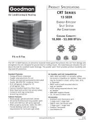
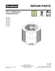
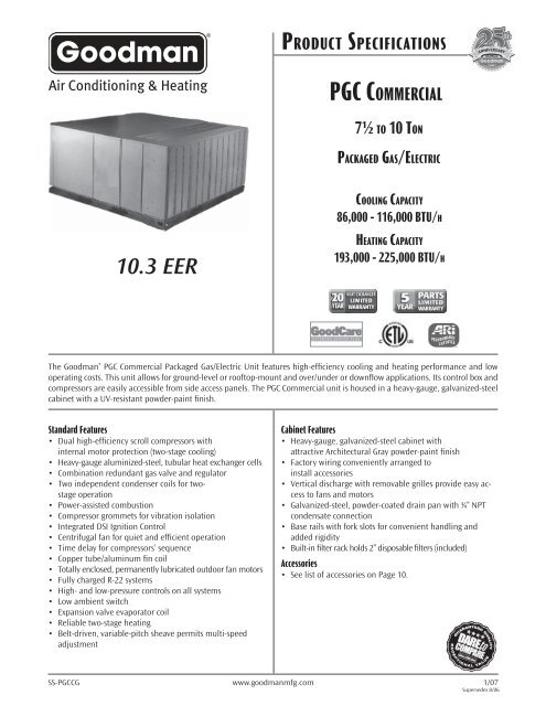
PRODUCT SPECIFICATIONS<br />
PGC COMMERCIAL<br />
7½ TO 10 TON<br />
PACKAGED GAS/ELECTRIC<br />
COOLING CAPACITY<br />
86,000 - 116,000 BTU/H<br />
10.3 EER<br />
HEATING CAPACITY<br />
193,000 - 225,000 BTU/H<br />
The Goodman ® PGC Commercial Packaged Gas/Electric Unit features high-efficiency cooling and heating performance and low<br />
operating costs. This unit allows for ground-level or rooftop-mount and over/under or downflow applications. Its control box and<br />
compressors are easily accessible from side access panels. The PGC Commercial unit is housed in a heavy-gauge, galvanized-steel<br />
cabinet with a UV-resistant powder-paint finish.<br />
Standard Features<br />
• Dual high-efficiency scroll compressors with<br />
internal motor protection (two-stage cooling)<br />
• Heavy-gauge aluminized-steel, tubular heat exchanger cells<br />
• Combination redundant gas valve and regulator<br />
• Two independent condenser coils for twostage<br />
operation<br />
• Power-assisted combustion<br />
• Compressor grommets for vibration isolation<br />
• Integrated DSI Ignition Control<br />
• Centrifugal fan for quiet and efficient operation<br />
• Time delay for compressors’ sequence<br />
• Copper tube/aluminum fin coil<br />
• Totally enclosed, permanently lubricated outdoor fan motors<br />
• Fully charged R-22 systems<br />
• High- and low-pressure controls on all systems<br />
• Low ambient switch<br />
• Expansion valve evaporator coil<br />
• Reliable two-stage heating<br />
• Belt-driven, variable-pitch sheave permits multi-speed<br />
adjustment<br />
Cabinet Features<br />
• Heavy-gauge, galvanized-steel cabinet with<br />
attractive Architectural Gray powder-paint finish<br />
• Factory wiring conveniently arranged to<br />
install accessories<br />
• Vertical discharge with removable grilles provide easy access<br />
to fans and motors<br />
• Galvanized-steel, powder-coated drain pan with ¾” NPT<br />
condensate connection<br />
• Base rails with fork slots for convenient handling and<br />
added rigidity<br />
• Built-in filter rack holds 2” disposable filters (included)<br />
Accessories<br />
• See list of accessories on Page 10.<br />
SS-PGCCG www.goodmanmfg.com 1/07<br />
Supersedes 8/06
PRODUCT SPECIFICATIONS<br />
NOMENCLATURE<br />
P G C 0 9 0 1 9 5 3 A<br />
Unit Type<br />
Packaged Gas/Electric<br />
(ASHRAE 90.1 Compliant)<br />
Revision<br />
Nominal Cooling Capacity<br />
090 = 7.5 tons / 90,000 BTU/h<br />
120 = 10 tons / 120,000 BTU/h<br />
Electrical Designator<br />
3 = 208/230 V, 3 Phase, 60 Hz<br />
4 = 460 V, 3 Phase, 60 Hz<br />
Nominal Heating Input<br />
195 - 193,000 BTUH (Full Fire) - 133,000 Low Fire<br />
225 - 225,000 BTUH (Full Fire) - 153,000 Low Fire<br />
2 www.goodmanmfg.com SS-PGCCG
PRODUCT SPECIFICATIONS<br />
SPECIFICATIONS<br />
PGC090195-3 PGC090195-4 PGC120225-3 PGC120225-4<br />
Cooling Capacity<br />
Total BTU/h 86,000 86,000 116,000 116,000<br />
Sensible BTU/h 63,600 63,600 85,000 85,000<br />
EER ² 10.3 10.3 10.3 10.3<br />
IPLV ³ 10.7 10.7 10.7 10.7<br />
Heating Capacity<br />
Max. Input BTU/h 193,000 193,000 225,000 225,000<br />
Min. Input BTU/h 133,000 133,000 153,000 153,000<br />
Output BTU/h 154,400 154,400 180,000 180,000<br />
AFUE 80% 80% 80% 80%<br />
Temperature Rise Range (°F) 35-65 35-65 30-60 30-60<br />
Indoor Blowers (2)<br />
Type Belt Belt Belt Belt<br />
Wheel (D x W) 12” x 12” 12” x 12” 12” x 15” 12” x 15”<br />
Indoor Nominal CFM 3,000 3,000 3,800 3,800<br />
Horsepower 1½ 1½ 3 3<br />
Evaporator Coil (1)<br />
Face Area (ft²) 11.2 11.2 14 14<br />
Rows Deep/ Fins per Inch 3/ 16 3/ 16 3/ 16 3/ 16<br />
Tube Diameter - Material ⅜” - Copper ⅜” - Copper ⅜” - Copper ⅜” - Copper<br />
Filter Size (ft²) / Quantity 25 x 25 x 2 / 3 25 x 25 x 2 / 3 16 x 25 x 2 / 3 16 x 25 x 2 / 3<br />
–– –– 20 x 25 x 2 / 3 20 x 25 x 2 / 3<br />
Condenser Fans (2) / Coil (1)<br />
Horsepower ½ ½ ½ ½<br />
Fan Diameter 24” 24” 24” 24”<br />
Outdoor Nominal CFM 5,500 5,500 6,400 6,400<br />
Face Area (ft²) 15.6 15.6 23.8 23.8<br />
Rows Deep/ Fins per Inch 2/ 21 2/ 21 2/ 21 2/ 21<br />
Tube Diameter - Material ⅜” - Copper ⅜” - Copper ⅜” - Copper ⅜” - Copper<br />
Electrical Data<br />
Voltage-Phase 208/230-3 460-3 208/230-3 460-3<br />
Compressor RLA/ LRA 12.5/ 88 5.9/ 44 17.4/ 123 6.8/ 49.5<br />
Indoor Blower FLA 4.2 2.1 8.4 4.2<br />
Outdoor Blower FLA 2.6 1.3 2.6 1.3<br />
Min. Circuit Ampacity 4 38.1 18.2 54.5 22.5<br />
Max. Overcurrent Device 5 60 30 70 35<br />
Operating Weight (lbs) 1,080 1,080 1,380 1,380<br />
Ship Weight (lbs) 1,100 1,100 1,400 1,400<br />
¹ Sensible capacity is gross, with no deduction for indoor motor heat<br />
² BTU/Watt @ 80/ 67° F inside; 95° F outside air<br />
³ IPLV = Integrated Part Load Valve<br />
4<br />
Wire size should be determined in accordance with National Electrical Codes. Extensive wire runs will require larger wire sizes.<br />
5<br />
HACR breakers may be used in place of fuses up to 60 amps<br />
SS-PGCCG www.goodmanmfg.com 3
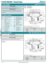
PRODUCT SPECIFICATIONS<br />
DIMENSIONS<br />
(Kit Required)<br />
Unit Size<br />
A<br />
(Height)<br />
B<br />
(Supply Air)<br />
C<br />
(Return Air)<br />
PGC090-X 36” “12½” “179/16”<br />
PGC120-X 52” “20¼” “2513/16”<br />
X= Electrical Designation<br />
4 www.goodmanmfg.com SS-PGCCG
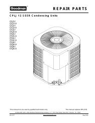
PRODUCT SPECIFICATIONS<br />
DIMENSIONS—ELECTRICAL CONNECTIONS<br />
1. Main power entrance location<br />
2. Control wiring entrance location<br />
3. Optional fi eld-installed internal disconnect switch<br />
4. Gas piping entrance location<br />
GAS PIPING CONNECTION SIZE<br />
Furnace Size<br />
195<br />
225<br />
Female NPT<br />
3/4”<br />
SS-PGCCG www.goodmanmfg.com 5
PRODUCT SPECIFICATIONS<br />
FAN PERFORMANCE DATA<br />
6 www.goodmanmfg.com SS-PGCCG
PRODUCT SPECIFICATIONS<br />
COMPONENT PRESSURE DROPS<br />
Model CFM Wet Coil<br />
PGC090-X<br />
PGC120-X<br />
Gas Furnace Section<br />
195 225<br />
Med. Efficiency<br />
Filters<br />
Econo. Return<br />
Air Damper<br />
2600 0.06 0.1 - 0.03 0.14<br />
3000 0.06 0.14 - 0.04 0.14<br />
3400 0.07 0.17 - 0.05 0.18<br />
3600 0.05 - 0.13 0.03 0.14<br />
4000 0.05 - 0.16 0.04 0.14<br />
4400 0.05 - 0.19 0.04 0.14<br />
COOLING CAPACITY DATA<br />
PGC090-X @ 3,000 CFM<br />
AMB.˚ F<br />
85<br />
90<br />
95<br />
100<br />
105<br />
EVAP. 75˚ F DB 80˚ F DB 85˚ F DB 90˚ F DB<br />
EAT KW MBHT MBHS KW MBHT MBHS KW MBHT MBHS KW MBHT MBHS<br />
61 WB 7.6 83.8 72.1 7.6 85.7 84.8 7.7 90.6 90.6 7.7 95.5 95.5<br />
64 WB 7.7 88.7 63.3 7.7 88.7 77.9 7.7 90.6 90.6 7.7 95.5 95.5<br />
67 WB 7.7 94.5 54.6 7.7 94.5 69.2 7.7 94.5 82.8 7.8 95.5 95.5<br />
70 WB 7.8 100.3 45.8 7.8 100.3 60.4 7.8 100.3 74.0 7.8 100.3 88.7<br />
73 WB 7.8 106.2 37.0 7.8 106.2 51.6 7.8 106.2 65.3 7.9 106.2 79.9<br />
61 WB 7.8 81.8 71.1 7.9 83.8 83.8 8.0 88.7 88.7 8.0 94.5 94.5<br />
64 WB 8.0 86.7 62.4 8.0 87.7 77.0 8.0 88.7 88.7 8.0 94.5 94.5<br />
67 WB 8.1 92.5 53.6 8.1 92.5 68.2 8.1 92.5 82.8 8.1 94.5 94.5<br />
70 WB 8.1 97.4 44.8 8.1 97.4 59.4 8.1 98.4 74.0 8.2 98.4 87.7<br />
73 WB 8.2 103.3 36.0 8.2 103.3 50.7 8.2 105.2 64.3 8.4 103.3 78.9<br />
61 WB 8.2 80.9 71.1 8.3 82.8 82.8 8.3 87.7 87.7 8.4 93.5 93.5<br />
64 WB 8.3 85.7 62.4 8.3 85.7 76.0 8.3 87.7 87.7 8.4 93.5 93.5<br />
67 WB 8.4 90.6 53.6 8.4 90.6 68.2 8.4 90.6 81.8 8.4 93.5 93.5<br />
70 WB 8.4 96.4 44.8 8.4 96.4 58.5 8.4 96.4 73.1 8.4 96.4 87.7<br />
73 WB 8.5 101.3 35.1 8.5 101.3 49.7 8.5 101.3 64.3 8.6 101.3 78.9<br />
61 WB 8.5 78.9 70.1 8.6 80.9 80.9 8.6 86.7 86.7 8.7 91.6 91.6<br />
64 WB 8.6 83.8 61.4 8.6 83.8 76.0 8.6 86.7 86.7 8.7 91.6 91.6<br />
67 WB 8.7 88.7 52.6 8.7 88.7 67.2 8.7 88.7 80.9 8.7 91.6 91.6<br />
70 WB 8.8 94.5 43.8 8.8 94.5 58.5 8.8 94.5 72.1 8.8 94.5 85.7<br />
73 WB 8.9 99.4 35.1 9.0 99.4 48.7 9.0 99.4 63.3 9.0 99.4 77.9<br />
61 WB 8.9 77.0 69.2 8.9 79.9 79.9 9.0 84.8 84.8 9.1 89.6 89.6<br />
64 WB 8.9 81.8 60.4 8.9 81.8 75.0 9.0 84.8 84.8 9.1 89.6 89.6<br />
67 WB 9.1 86.7 51.6 9.1 86.7 66.3 9.1 86.7 79.9 9.1 89.6 89.6<br />
70 WB 9.1 91.6 42.9 9.1 91.6 57.5 9.2 92.5 71.1 9.2 92.5 85.7<br />
73 WB 9.4 98.4 34.1 9.4 98.4 48.7 9.4 98.4 62.4 9.4 98.4 77.0<br />
Notes:<br />
1. Capacities are gross and are based on 230, 460 operation. 208-volt<br />
operation must be derated by 0.98. Gross capacities do not include<br />
evaporator motor heat<br />
2. KW is for entire unit.<br />
3 See table for capacity correction factors at other than nominal CFM.<br />
SHADED AREA REPRESENTS 100% SENSIBLE COOLING.<br />
AMB Ambient Air Temperature<br />
EAT Entering Air Temperature<br />
DB Evaporator Dry Bulb EAT<br />
WB Evaporator Wet Bulb EAT<br />
KW 1,000 Watts<br />
MBHT 1,000 BTU/h Total Cooling<br />
MBHS 1,000 BTU/h Sensible Cooling<br />
CFM Evaporator Airfl ow Ft.³/min (Table 9a)<br />
SS-PGCCG www.goodmanmfg.com 7
PRODUCT SPECIFICATIONS<br />
COOLING CAPACITY DATA (CONT.)<br />
PGC120-X @ 4,000 CFM<br />
AMB.˚ F<br />
85<br />
90<br />
95<br />
100<br />
105<br />
EVAP. 75˚ F DB 80˚ F DB 85˚ F DB 90˚ F DB<br />
EAT KW MBHT MBHS KW MBHT MBHS KW MBHT MBHS KW MBHT MBHS<br />
61 WB 10.2 115.9 99.7 10.2 118.6 117.2 10.3 125.3 125.3 10.3 132.0 132.0<br />
64 WB 10.3 122.6 87.6 10.3 122.6 107.8 10.3 125.3 125.3 10.3 132.0 132.0<br />
67 WB 10.3 130.7 75.4 10.3 130.7 95.6 10.3 130.7 114.5 10.5 132.0 132.0<br />
70 WB 10.6 138.8 63.3 10.6 138.8 83.5 10.6 138.8 102.4 10.6 138.8 122.6<br />
73 WB 10.6 146.9 51.2 10.6 146.9 71.4 10.6 146.9 90.3 10.7 146.9 110.5<br />
61 WB 10.6 113.2 98.3 10.7 115.9 115.9 10.8 122.6 122.6 10.8 130.7 130.7<br />
64 WB 10.8 119.9 86.2 10.8 121.3 106.4 10.8 122.6 122.6 10.8 130.7 130.7<br />
67 WB 10.9 128.0 74.1 10.9 128.0 94.3 10.9 128.0 114.5 10.9 130.7 130.7<br />
70 WB 10.9 134.7 62.0 10.9 134.7 82.2 10.9 136.1 102.4 11.0 136.1 121.2<br />
73 WB 11.0 142.8 49.8 11.0 142.8 70.1 11.0 145.5 88.9 11.3 142.8 109.1<br />
61 WB 11.0 111.8 98.3 11.1 114.5 114.5 11.1 121.3 121.2 11.3 129.3 129.3<br />
64 WB 11.1 118.6 86.2 11.1 118.6 105.1 11.1 121.3 121.2 11.3 129.3 129.3<br />
67 WB 11.3 125.3 74.1 11.3 125.3 94.3 11.3 125.3 113.2 11.4 129.3 129.3<br />
70 WB 11.3 133.4 62.0 11.4 133.4 80.8 11.4 133.4 101.0 11.4 133.4 121.2<br />
73 WB 11.5 140.1 48.5 11.5 140.1 68.7 11.5 140.1 88.9 11.6 140.1 109.1<br />
61 WB 11.5 109.1 97.0 11.6 111.8 111.8 11.6 119.9 119.9 11.7 126.6 126.6<br />
64 WB 11.6 115.9 84.9 11.6 115.9 105.1 11.6 119.9 119.9 11.7 126.6 126.6<br />
67 WB 11.7 122.6 72.7 11.7 122.6 93.0 11.7 122.6 111.8 11.7 126.6 126.6<br />
70 WB 11.8 130.7 60.6 11.8 130.7 80.8 11.8 130.7 99.7 11.8 130.7 118.5<br />
73 WB 12.0 137.4 48.5 12.2 137.4 67.4 12.2 137.4 87.6 12.2 137.4 107.8<br />
61 WB 12.0 106.4 95.6 12.0 110.5 110.5 12.2 117.2 117.2 12.3 124.0 123.9<br />
64 WB 12.0 113.2 83.5 12.0 113.2 103.7 12.2 117.2 117.2 12.3 124.0 123.9<br />
67 WB 12.3 119.9 71.4 12.3 119.9 91.6 12.3 119.9 110.5 12.3 124.0 123.9<br />
70 WB 12.3 126.6 59.3 12.3 126.6 79.5 12.4 128.0 98.3 12.4 128.0 118.5<br />
73 WB 12.6 136.1 47.2 12.6 136.1 67.4 12.6 136.1 86.2 12.6 136.1 106.4<br />
Notes:<br />
1. Capacities are gross and are based on 230, 460 operation. 208-volt AMB Ambient Air Temperature KW 1,000 Watts<br />
operation must be derated by 0.98. Gross capacities do not include EAT Entering Air Temperature MBHT 1,000 BTU/h Total Cooling<br />
evaporator motor heat<br />
2. KW is for entire unit.<br />
DB Evaporator Dry Bulb EAT MBHS 1,000 BTU/h Sens. Cooling<br />
3 See table for capacity correction factors at other than nominal CFM.<br />
WB Evaporator Wet Bulb EAT CFM Evaporator Airfl ow Ft.³/min<br />
SHADED AREA REPRESENTS 100% SENSIBLE COOLING.<br />
COOLING CAPACITY CORRECTION FACTORS<br />
CFM<br />
-15% -10% -5% STD. +5% +10% +15%<br />
Total MBH 0.971 0.985 0.991 0 1.006 1.012 1.019<br />
Sensible MBH 0.925 0.952 0.974 0 1.024 1.048 1.070<br />
kW 0.985 0.989 0.995 0 1.004 1.006 1.011<br />
EVAPORATOR MOTOR HEAT<br />
Horsepower BTU/h<br />
1.5 4,650<br />
3 9,300<br />
8 www.goodmanmfg.com SS-PGCCG
PRODUCT SPECIFICATIONS<br />
HEATING CAPACITY DATA<br />
GAS HEAT AIR TEMPERATURE RISE<br />
CFM<br />
Model 195 225<br />
Number of Tubes 6 7<br />
Ventor Motor HP 1/16 1/12<br />
MBH Input 193 225<br />
MBH Output 154.4 180.0<br />
Max. Air Temperature Rise 65 60<br />
2,600 55.0 -<br />
2,800 51.1 -<br />
3,000 47.7 55.6<br />
3,200 44.7 52.1<br />
3,400 42.1 49.1<br />
3,600 39.7 46.3<br />
3,800 - 43.9<br />
4,000 - 41.7<br />
4,200 - 39.7<br />
4,400 - 37.9<br />
4,600 - 36.3<br />
NOTES:<br />
1. See Gas Furnace Air Temperature Rise table for furnace availability in various unit sizes.<br />
2. Capacities are approved for altitudes to 2,000’. At higher elevations, heating capacity must be reduced 4% (x0.96) for each 1,000’<br />
above sea level.<br />
3. Air temperature rise is for total heating capacity. Temperature rises at other conditions may be calculated by using the formula:<br />
Temperature Rise = Output Capacity - BTU/h<br />
1.08 x ft.³/min. Airfl ow<br />
4. For altitudes over 2,000’, air temperature rise must be calculated using the formula:<br />
Temperature Rise = Output Capacity - BTU/h<br />
14.4 x ft.³/min. Airfl ow x Specifi c Weight of Air<br />
5. Two-stage control is standard.<br />
6. Output capacity based on nominal 1,000 BTU/Ft.³ natural gas or 2,500 Btu/Ft.³ propane.<br />
GAS FURNACE AIR TEMPERATURE RISE<br />
Unit Size<br />
Model Number<br />
195 225<br />
7½ X N/A<br />
10 N/A X<br />
X - Furnace Available<br />
N/A - Furnace Not Available<br />
SS-PGCCG www.goodmanmfg.com 9
PRODUCT SPECIFICATIONS<br />
ACCESSORIES<br />
THERMOSTAT (CHT90-120)<br />
TWO-STAGE COOL AND TWO-STAGE HEAT THERMOSTAT WITH SUBBASE, MANUAL CHANGEOVER, FAN ON OR AUTO.<br />
Note: A variety of thermostat configurations can be used on this equipment based on the application needs.<br />
For example, our CHTS36-60 can be used if two-stage cooling and single-stage heat is desired. Our CHT18-60<br />
can be used if single-stage cooling and heating is desired. A single-stage cooling and two-stage heating<br />
thermostat can be used.<br />
ROOFTOP LIFT KIT (RLK90-120)<br />
Kit consists of four ½” shackles that are used to lift the equipment into position on a roof, etc. The shackles<br />
are to be attached to the mounting holes in the base rails. Wire or strap material along with field supplied<br />
spreader bars are employed to complete the lifting assembly (see rigging detail).<br />
LOW AMBIENT CONTROL (LA-01)<br />
Liquid temperature- (or pressure-) operated solid state control that varies the speed of one of the condenser fans.<br />
Low ambient control reduces fan motor RPM as liquid temperature (or pressure) decreases. Caution: If control is<br />
used below 50 °F, accumulators should be added to the equipment to avoid slugging of the compressors.<br />
ROOF CURB (PGC-5)<br />
Full perimeter curb for equipment in the down discharge application. Curb includes provisions for duct attachment<br />
prior to setting unit. Curb is shipped knocked down with all necessary hardware and gasket material.<br />
MANUAL AND MOTORIZED FRESH AIR DAMPERS (PGMD-5 & PGMDM-5)<br />
Manual damper is fixed position type for 0 to 25% fresh air. Motorized damper is a field-adjustable mechanical<br />
damper for 0 to 25% fresh air. Damper automatically closes when blower stops.<br />
ECONOMIZERS (PGED090/102-5A & PGED120/180-5A, PGEH090/102-5 & PGEH120/180-5)<br />
Fully modulating, enthalpy-controlled economizers shipped with major components pre-assembled. Plug<br />
assembly on equipment and economizer provides easy foolproof wiring.<br />
HORIZONTAL DUCT KIT (PGHDK090/102-5A & PGHDK120/180-5A)<br />
The unit is shipped in the downflow (vertical) duct configuration. The horizontal duct kit must be installed in<br />
the field for horizontal duct configuration.<br />
PANEL LOUVER KIT (PLK090/102-5 & PLK120/180-5)<br />
Louvered panels for condenser coil protection.<br />
LIQUID PROPANE KIT (LPW-06)<br />
Kit consists of an L.P. two-stage gas valve and main gas orifices to convert appliance from natural gas to liquid<br />
propane fuel.<br />
10 www.goodmanmfg.com SS-PGCCG
PRODUCT SPECIFICATIONS<br />
THIS PAGE HAS BEEN INTENTIONALLY LEFT BLANK.<br />
SS-PGCCG www.goodmanmfg.com 11
PRODUCT SPECIFICATIONS<br />
Goodman Manufacturing Company, L.P., reserves the right to discontinue, or change at any<br />
time, specifi cations or designs without notice or without incurring obligations.<br />
Copyright © 2007 • Goodman Manufacturing Company, L.P. • Houston, Texas<br />
Printed in the USA.<br />
12 www.goodmanmfg.com SS-PGCCG