Controllers: Honeywell HC900 Hybrid Controller ... - Industrial Controls
Controllers: Honeywell HC900 Hybrid Controller ... - Industrial Controls
Controllers: Honeywell HC900 Hybrid Controller ... - Industrial Controls

You also want an ePaper? Increase the reach of your titles
YUMPU automatically turns print PDFs into web optimized ePapers that Google loves.
51-52-03-31<br />
4/6/05<br />
Page 1 of 16<br />
<strong>HC900</strong> <strong>Hybrid</strong> <strong>Controller</strong><br />
Specification<br />
Applications<br />
Pump stations<br />
Boilers<br />
Water treatment<br />
Pilot operations<br />
Fermenters<br />
Utility DAQ<br />
Furnaces<br />
Kilns<br />
Autoclaves<br />
Extruders<br />
Reactors<br />
Retorts<br />
Sterilizers<br />
Crystal Growing<br />
Dryers<br />
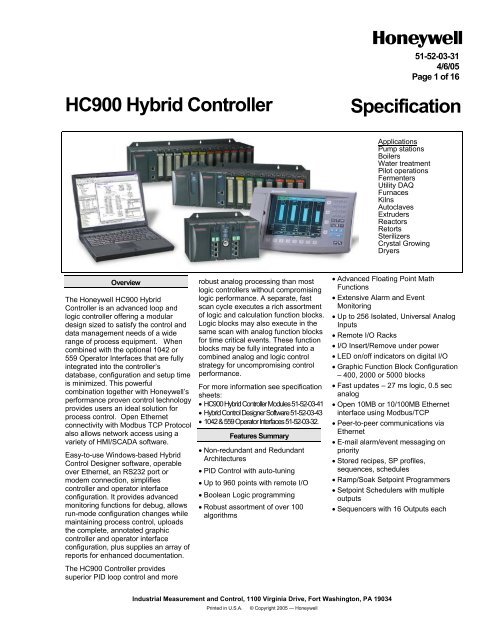
Overview<br />
The <strong>Honeywell</strong> <strong>HC900</strong> <strong>Hybrid</strong><br />
<strong>Controller</strong> is an advanced loop and<br />
logic controller offering a modular<br />
design sized to satisfy the control and<br />
data management needs of a wide<br />
range of process equipment. When<br />
combined with the optional 1042 or<br />
559 Operator Interfaces that are fully<br />
integrated into the controller’s<br />
database, configuration and setup time<br />
is minimized. This powerful<br />
combination together with <strong>Honeywell</strong>’s<br />
performance proven control technology<br />
provides users an ideal solution for<br />
process control. Open Ethernet<br />
connectivity with Modbus TCP Protocol<br />
also allows network access using a<br />
variety of HMI/SCADA software.<br />
Easy-to-use Windows-based <strong>Hybrid</strong><br />
Control Designer software, operable<br />
over Ethernet, an RS232 port or<br />
modem connection, simplifies<br />
controller and operator interface<br />
configuration. It provides advanced<br />
monitoring functions for debug, allows<br />
run-mode configuration changes while<br />
maintaining process control, uploads<br />
the complete, annotated graphic<br />
controller and operator interface<br />
configuration, plus supplies an array of<br />
reports for enhanced documentation.<br />
The <strong>HC900</strong> <strong>Controller</strong> provides<br />
superior PID loop control and more<br />
robust analog processing than most<br />
logic controllers without compromising<br />
logic performance. A separate, fast<br />
scan cycle executes a rich assortment<br />
of logic and calculation function blocks.<br />
Logic blocks may also execute in the<br />
same scan with analog function blocks<br />
for time critical events. These function<br />
blocks may be fully integrated into a<br />
combined analog and logic control<br />
strategy for uncompromising control<br />
performance.<br />
For more information see specification<br />
sheets:<br />
• <strong>HC900</strong> <strong>Hybrid</strong> <strong>Controller</strong> Modules 51-52-03-41<br />
• <strong>Hybrid</strong> Control Designer Software 51-52-03-43<br />
• 1042 & 559 Operator Interfaces 51-52-03-32.<br />
Features Summary<br />
• Non-redundant and Redundant<br />
Architectures<br />
• PID Control with auto-tuning<br />
• Up to 960 points with remote I/O<br />
• Boolean Logic programming<br />
• Robust assortment of over 100<br />
algorithms<br />
• Advanced Floating Point Math<br />
Functions<br />
• Extensive Alarm and Event<br />
Monitoring<br />
• Up to 256 Isolated, Universal Analog<br />
Inputs<br />
• Remote I/O Racks<br />
• I/O Insert/Remove under power<br />
• LED on/off indicators on digital I/O<br />
• Graphic Function Block Configuration<br />
– 400, 2000 or 5000 blocks<br />
• Fast updates – 27 ms logic, 0.5 sec<br />
analog<br />
• Open 10MB or 10/100MB Ethernet<br />
interface using Modbus/TCP<br />
• Peer-to-peer communications via<br />
Ethernet<br />
• E-mail alarm/event messaging on<br />
priority<br />
• Stored recipes, SP profiles,<br />
sequences, schedules<br />
• Ramp/Soak Setpoint Programmers<br />
• Setpoint Schedulers with multiple<br />
outputs<br />
• Sequencers with 16 Outputs each<br />
<strong>Industrial</strong> Measurement and Control, 1100 Virginia Drive, Fort Washington, PA 19034<br />
Printed in U.S.A. © Copyright 2005 — <strong>Honeywell</strong>
51-52-03-31<br />
Page 2<br />
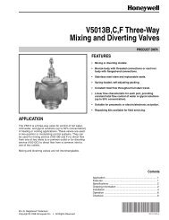
Non-redundant Architectures<br />
Ethernet 10Base-T<br />
100 m<br />
Process<br />
1042-OI or<br />
<strong>HC900</strong><br />
3 rd party OI<br />
RS-485 twisted pair<br />
Single process/single rack<br />
1042-OI<br />
E-Net<br />
Hub<br />
<strong>HC900</strong><br />
Process<br />
Ethernet 10Base-T<br />
100m each<br />
100m each<br />
Single process/ multiple remote I/O Racks
51-52-03-31<br />
Page 3<br />
Non-redundant Architectures<br />
Remote I/O<br />
Rack<br />
Process A<br />
E-Net<br />
Hub/Switch<br />
Process B<br />
PC HMI<br />
1042-OI<br />
Ethernet 10Base-T<br />
100m each<br />
100m each<br />
E-Net<br />
Hub<br />
Process C<br />
Multiple processes/multiple racks<br />
Remote I/O<br />
Racks
51-52-03-31<br />
Page 4<br />
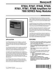
<strong>HC900</strong> <strong>Controller</strong><br />
• The rack based <strong>HC900</strong> <strong>Controller</strong> is<br />
available in 3 rack sizes with 4, 8 or<br />
12 I/O slots each to support a wide<br />
range of requirements.<br />
• Dual Redundant <strong>HC900</strong> controllers<br />
use a separate controller rack for<br />
CPUs without local I/O. Two power<br />
supplies provide separate CPU<br />
power. A redundant controller switch<br />
module provides status and performs<br />
mode changes.<br />
CPU Modules<br />
• The CPU options available for the<br />
<strong>HC900</strong> <strong>Controller</strong> include the C30<br />
and C50 for non-redundant<br />
applications and the C70R for<br />
redundant CPU applications.<br />
• All <strong>HC900</strong> CPU modules offer open<br />
Ethernet communications for access<br />
by a variety of HMI and SCADA<br />
software applications and peer to<br />
peer communications for control data<br />
exchanges between controllers. The<br />
C70R provides redundant Ethernet<br />
ports for high network availability<br />
installations.<br />
• <strong>HC900</strong> CPU modules use a dual<br />
scan method to handle fast digital<br />
scanning and normal analog input<br />
scanning in the same integrated<br />
control environment. Both scans<br />
support a wide range of<br />
computational function block<br />
algorithms and a user adjustable<br />
execution sequence order.<br />
• <strong>HC900</strong> CPUs use Flash memory for<br />
permanent user configuration<br />
program storage and battery-backed<br />
memory for dynamic data storage<br />
allowing for graceful recovery<br />
following a power interruption or<br />
other discontinuous operations.<br />
CPU I/O Scanners<br />
<strong>HC900</strong> Remote I/O is processed and<br />
communicated to the main CPU<br />
module through a remote I/O Scanner<br />
module. Two I/O scanner modules are<br />
available, a single port model for nonredundant<br />
CPU systems and a dual<br />
port model for redundant CPU<br />
systems. Scanner addressing in multirack<br />
systems are jumper selectable for<br />
single port scanners and via switch<br />
setting for dual port scanners.<br />
Inputs and Outputs - A variety of I/O<br />
modules are available for selection in<br />
creating a custom control solution.<br />
These include:<br />
• 8 point universal analog input<br />
module: Inputs may be mixed on a<br />
module and may include multiple<br />
thermocouple types, RTDs, ohms,<br />
voltage or millivoltage types. High<br />
point to point isolation simplifies<br />
installation and saves the expense of<br />
external isolation hardware.<br />
• 4 point isolated analog output<br />
module: Supports from 0 to 20mA<br />
each.<br />
• 16 point digital input cards: Contact<br />
closure type, DC voltage and AC<br />
voltage types.<br />
• 8 point AC or 16 point DC digital<br />
output cards<br />
• 8 point relay output card: four form C<br />
type and four form A type relays.<br />
See Module Specification sheet 51-52-<br />
03-41 for details.<br />
Insert & removal of I/O under power-<br />
For ease of maintenance, the <strong>HC900</strong><br />
controller supports removing and<br />
inserting I/O modules from the card<br />
rack without removing power from the<br />
controller. Each card is sensed for<br />
validity by the controller and autoconfigured<br />
on insertion.<br />
I/O Terminal Blocks - Terminal Blocks<br />
are available with either barrier style or<br />
Euro style screw connections. A<br />
module label area is provided for field<br />
wiring identification.<br />
Remote I/O - I/O racks may be<br />
remotely mounted from the controller<br />
via a dedicated Ethernet 10Base-T<br />
(100Base-T with C70R) connection at<br />
up to 300 meters (984 feet) between<br />
the controller and the most remote rack<br />
using two Ethernet hubs.<br />
Remote Terminal Panels - Optional<br />
DIN rail mounted Remote Terminal<br />
Panels (RTPs) are available for use<br />
with pre-wired cables to reduce<br />
installation time and labor expense.<br />
RTP types available: analog input,<br />
relay output, discrete input, discrete<br />
output, analog output. Three cable<br />
lengths are also available to match<br />
hardware to installation variations.<br />
See Module Specification sheet 51-52-<br />
03-41 for more details.<br />
Redundant Power - A second<br />
(backup) power module may be added<br />
to each <strong>HC900</strong> controller rack . An<br />
extended rack is available that<br />
expands the standard I/O rack to<br />
accommodate a second (redundant)<br />
power supply and power status<br />
module.<br />
Table 1 CPU Capacities<br />
Function Point per Module Max. for C30 CPU Max. for C50 CPU Max. for C70R CPU<br />
Analog In 8 96 256 256<br />
Analog Out 4 48 64 64<br />
Digital In 16 192 960 960<br />
Digital Out 8 AC or 16 DC 192 960 960<br />
Function Blocks 400 2000 5000<br />
PID Loops 8 32 32
51-52-03-31<br />
Page 5<br />
Redundant Architectures<br />
Ethernet<br />
Switch<br />
10/100 base-T<br />
Experion Vista<br />
or 3 rd Party<br />
Software<br />
RS-485<br />
Twisted Pair<br />
A<br />
100 base-T<br />
Up to 100m<br />
B<br />
Process<br />
Single process/ Non-redundant network<br />
10/100 baseT<br />
Ethernet<br />
Switch<br />
Peer to Peer<br />
Data Exchange<br />
Ethernet<br />
Switch<br />
A<br />
100 baseT<br />
B<br />
Ethernet<br />
Switch<br />
A<br />
B<br />
100 baseT<br />
Ethernet Switch<br />
for added distance<br />
Process<br />
Multiple systems/ multiple I/O Racks
51-52-03-31<br />
Page 6<br />
Redundant Architectures<br />
Ethernet<br />
Switch<br />
10/100 base-T<br />
Experion Vista<br />
or 3 rd Party<br />
Software<br />
OPC Server<br />
with Dual<br />
Ethernet support<br />
Ethernet<br />
Switch<br />
A<br />
100 base-T<br />
B<br />
Process<br />
Single process, multiple I/O racks, redundant networks
51-52-03-31<br />
Page 7<br />
Redundant <strong>Controller</strong><br />
Two redundant C70R CPUs operate in<br />
a separately mounted controller rack,<br />
each with an independent power<br />
supply. A Redundant Switch Module<br />
(RSM) is located in the rack between<br />
the two C70R CPUs. A key switch on<br />
the RSM allows the user to change the<br />
operating mode of the Lead CPU.<br />
There is no I/O in the controller rack;<br />
the CPUs communicate with up to 5<br />
racks of I/O over a 100 base-T<br />
Ethernet physical communication link.<br />
When more than one I/O rack is used<br />
in the system, Ethernet switching hubs<br />
are required, one for each Scanner<br />
connection. In operation, all control<br />
functions and host communication<br />
exchanges are handled by the Lead<br />
controller, including configuration and<br />
operator changes. The Lead controller<br />
updates the Reserve controller with all<br />
the information needed to assume<br />
control in the event of a fault condition.<br />
After power-up of the C70R CPUs, the<br />
first available CPU assumes the Lead<br />
function. The Lead may be transferred<br />
to the Reserve controller by:<br />
• failure of the Lead controller,<br />
• manually changing a keyed switch<br />
located on the Redundant Switch<br />
Module, or<br />
• instruction from host communication.<br />
Redundant Networks for Host<br />
communications are provided on the<br />
C70R CPU. Both network ports are<br />
continuously active on the Lead<br />
controller. The network ports on the<br />
Reserve CPU are not available for<br />
external communications. An OPC<br />
server is available from <strong>Honeywell</strong> to<br />
support redundant Ethernet<br />
communications and automatically<br />
transfer communications.<br />
The C70R network ports may<br />
otherwise be used in non-redundant<br />
mode where only one of the<br />
communication ports is used.<br />
Remote I/O - Up to two Ethernet<br />
switches may be used in each I/O<br />
connection to extend the distance<br />
between the CPU rack and the most<br />
distant I/O rack to 300m, 984 feet.<br />
Operator Interface - 1042 and 559<br />
series operator Interfaces are<br />
supported with the C70R CPU. The<br />
RS-485 serial connection is made to<br />
the serial communication ports of both<br />
CPUs. The operator interface<br />
communication to the controller follows<br />
the Lead controller assignment.<br />
Status/Diagnostics - An output<br />
parameter of the system monitor<br />
function block of C70R CPUs provides<br />
a digital status of the Reserve<br />
controller to allow integration of this<br />
information into the control strategy.<br />
C70R CPUs also provide diagnostic<br />
status on redundancy operation that<br />
may be observed using <strong>Hybrid</strong> Control<br />
Designer configuration software. A<br />
Redundancy status function block is<br />
also available to monitor redundant<br />
controller operation. A single C70R<br />
CPU cannot be used without a<br />
redundant CPU; this will cause ongoing<br />
background diagnostic reporting.<br />
Function Blocks<br />
Advanced control and computational<br />
capability - A large assortment of<br />
analog and digital function blocks are<br />
available to solve the most demanding<br />
control requirements. Function blocks<br />
are grouped by scan rate, fast or<br />
normal, and by function, Principal or<br />
Standard.<br />
Function Block execution - All<br />
function blocks operate synchronously<br />
with I/O processing. Inputs are<br />
measured at the start of every scan<br />
and outputs are updated at the end of<br />
every scan. Function blocks such as<br />
Time Proportioning Outputs (TPO) and<br />
Position Proportioning outputs (PP)<br />
require higher output resolution and<br />
are updated when the function blocks<br />
are executing. Micro-controllers on<br />
digital I/O modules can maintain TPO<br />
duty cycle operation during failsafe<br />
conditions. Micro-controllers on all I/O<br />
modules allow outputs to be configured<br />
to assume a default state in the event<br />
of a fault condition.<br />
Normal Scan: Function blocks that<br />
execute during the Normal Scan are<br />
synchronized to the analog input<br />
measurements. The fastest update<br />
rate is 500ms.<br />
Fast Scan: The fastest update rate for<br />
fast scan function blocks in a single<br />
controller rack is 27ms. The update<br />
rate starts at 53ms when remote racks<br />
are used and for redundant systems.<br />
Principal Function Blocks – These<br />
function blocks are supported by<br />
dedicated displays on 1042 and 559<br />
series operator interfaces. They have<br />
Tag names and other attributes to<br />
support on-line user interaction.<br />
Typical Principal function blocks<br />
include PID, Set Point Programming,<br />
Sequencers, Alternators, Stage, etc.<br />
Standard Function Blocks – The<br />
number of standard function blocks<br />
that may be used in a configuration is<br />
virtually unlimited. Typical Standard<br />
blocks include totalizers, free-form<br />
math, average, mass flow, function<br />
generator, periodic timers based on<br />
real-time, carbon potential, RH, Dew<br />
Point, signal selection, comparison,<br />
and many others. These blocks may<br />
be configured to create control<br />
schemes that precisely address the<br />
needs of your process.<br />
Digital status outputs are also provided<br />
on many of the analog function blocks<br />
to facilitate intelligent signal alarming<br />
and default operation strategies.<br />
Typical logic function blocks include<br />
AND, OR, XOR, NOT, Latch, Flip-flop,<br />
On/Off Delay and Resettable timers,<br />
Counters, Free-form Boolean logic and<br />
more. The execution of analog and<br />
digital functions is seamlessly<br />
integrated into a single control strategy<br />
in the controller.<br />
Recipes<br />
Recipes are groups of data defined by<br />
the user that are used to make multiple<br />
value changes in the controller through<br />
a single action. Function block types<br />
that accept recipe data and the<br />
quantity of recipes stored in the<br />
controller are listed in Table 2.<br />
Recipes may also include Variables,<br />
which are dynamic analog and digital<br />
values used as inputs to standard and<br />
principal function blocks. Recipes may<br />
be loaded through the 1024 and 559<br />
operator interfaces by name or<br />
number, or via a dedicated recipe load<br />
function block and user configured<br />
logic.<br />
Alarms/Events<br />
Alarms and events represent changes<br />
in digital status that require user<br />
notification. The <strong>HC900</strong> controller<br />
supports an internal alarm<br />
annunciation system that may be setup<br />
to operate with 1042 and 559 operator<br />
interfaces or via e-mail to a remote<br />
computer (see Communications, E-<br />
mail Alarming). Up to 240 alarm points<br />
per controller may be grouped in 20<br />
groups of 12.<br />
Events are digital status changes that<br />
cause messages to be presented on<br />
1042 and 559 operator interfaces.<br />
They may prompt e-mail messages, do<br />
not require acknowledgement, and are<br />
reported and logged in a separate<br />
group. Up to 64 event points are<br />
supported in a controller.<br />
Alarms and events are time stamped in<br />
the controller to a one second<br />
resolution.
51-52-03-31<br />
Page 8<br />
Table 2 Recipe capacities<br />
Function Description Content Recipe size # of recipes stored<br />
Setpoint Profiles<br />
Ramp/Soak values, times and event 50 Segments 99<br />
Programs<br />
actions<br />
Setpoint Schedules<br />
Ramp/Soak values, times and event 50 Segments 20<br />
Schedules<br />
actions<br />
Sequencer Sequences State sequence, analog values 64 steps 10<br />
Variable Recipe Variables Analog and digital values 50 Variables 99<br />
Configuration<br />
<strong>Controller</strong> configuration is<br />
performed using <strong>Hybrid</strong> Control<br />
Designer Configuration software<br />
on a PC operating with a Mcrosoft<br />
Windows® operating system.<br />
Configuration files may be built<br />
independently on the PC and<br />
downloaded to the controller in a<br />
separate operation. Validation of<br />
proper physical I/O to support the<br />
configuration is provided along<br />
with appropriate warnings.<br />
Configuration Back-build - In the<br />
event a PC configuration file is lost<br />
or misplaced, it can be easily<br />
reconstructed using the upload<br />
function of the <strong>Hybrid</strong> Control<br />
Designer configuration software.<br />
Simply read the configuration from<br />
the controller to exactly duplicate<br />
the original configuration, including<br />
all text descriptions and operator<br />
interface display selections.<br />
Configuration edit - In the event<br />
edits to a controller’s configuration<br />
are required after the unit is in<br />
operation, an uploaded file may<br />
monitored during process<br />
operation, edited, and downloaded<br />
with the on-line download function<br />
of the <strong>HC900</strong> <strong>Hybrid</strong> Control<br />
Designer. The software allows<br />
configuration changes while in the<br />
Run mode, limiting process<br />
disturbances.<br />
Operator Interfaces<br />
<strong>HC900</strong> system supports a choice<br />
of two operator interfaces that are<br />
integrated into the database<br />
configuration of the controller. The<br />
model 1042 provides a 10-inch<br />
color display and the model 559<br />
offers a 5-inch color display. The<br />
full configuration of these operator<br />
interfaces is stored in the database<br />
of the controller and loaded into<br />
the interface on power-up. See<br />
specification sheet 51-52-03-32 for<br />
more information on these<br />
interfaces.<br />
Communications<br />
Remote I/O Rack Port (C50,<br />
C70R) – An Ethernet port is<br />
dedicated to supporting remote I/O<br />
racks. This 10Base-T<br />
connection on the C50 CPU supports a<br />
single direct connected remote rack or<br />
up to 4 remote racks when connected<br />
through an external Ethernet switching<br />
hub. The C70R CPU uses a 100base-<br />
T connection to support a single direct<br />
connected rack or up to 5 remote racks<br />
using external switching hubs.<br />
User Interface Support – An RS 485<br />
port provides communications between<br />
the controller and a 1042 or 559<br />
Operator Interface. This port supports<br />
a single Operator Interface for<br />
distances up to 2000 feet (609 meters)<br />
between the controller and operator<br />
interface. The <strong>Honeywell</strong> Operator<br />
Interface configuration is stored in the<br />
controller CPU and is loaded into the<br />
operator interface on startup.<br />
3rd party user Interface support is<br />
provided through RS232 and/or RS485<br />
port connections using Modbus/RTU<br />
protocol, or Ethernet with Modbus/TCP<br />
protocol.<br />
Ethernet Communications –<strong>HC900</strong><br />
controllers communicate with their host<br />
PC interfaces over an Ethernet<br />
10Base-T (C30/C50) or 10/100Base-T<br />
(C70R) communication network using<br />
the Modbus/TCP protocol, an open<br />
protocol interface available for most<br />
popular HMI software packages. The<br />
C30 and C50 support up to 5 host<br />
connections while the C70R supports<br />
up to 10 host connections concurrently.<br />
over an Ethernet network for control<br />
supervision and data acquisition. The<br />
<strong>Hybrid</strong> Control Designer software can<br />
also address any of the controllers<br />
concurrently over Ethernet for<br />
configuration monitoring, diagnostic<br />
interrogation, upload/ download, or online<br />
configuration changes. As a result,<br />
a <strong>HC900</strong> network of controllers and<br />
operator interfaces can be partitioned<br />
into process segments to assure<br />
proper control performance. Each of<br />
these process segments, in turn, can<br />
be accessed via common HMI<br />
software within the plant environment<br />
using an Ethernet LAN.<br />
Ethernet Peer to Peer<br />
Communications - Peer data<br />
communications between one <strong>HC900</strong><br />
controller and up to 8 other <strong>HC900</strong><br />
controllers is supported over Ethernet<br />
via UDP protocol for process interlocks<br />
or data sharing. Both digital and analog<br />
data exchange are supported using<br />
peer data exchange function blocks, up<br />
to 1024 parameters between peer<br />
controllers. No specialized software is<br />
required. Peer data can be given signal<br />
tag references for use in a control or<br />
data acquisition strategy. Peer to peer<br />
data interchange does not consume<br />
one of the host connections.<br />
Serial Modbus RTU<br />
Communications - Serial Modbus<br />
RTU communications is available on<br />
the RS232 and RS485 (2 wire) ports of<br />
the <strong>HC900</strong> <strong>Controller</strong> C50, C30 and<br />
C70R CPU assemblies in a Master or<br />
Slave mode. The protocol of these<br />
ports is user selectable between ELN<br />
protocol for use with HC Designer<br />
software and <strong>Honeywell</strong> operator<br />
interfaces, or Serial Modbus to<br />
interface with other compatible<br />
devices.<br />
Modbus RTU Slave - The RS232 and<br />
RS485 ports may be configured for<br />
simultaneous operation as a Modbus<br />
slave port to allow each to<br />
communicate with a single Modbus<br />
master. The Modbus protocol supports<br />
read and write access to variety of<br />
controller parameters using predefined<br />
address locations. In addition, a 1000<br />
register array is available to allow the<br />
user to specify the address locations of<br />
specific controller data to optimize<br />
controller communications. The data<br />
in the array may also be accessed in<br />
user specified formats (data types)<br />
such as analog data in Float 32,<br />
unsigned 16, signed 16, unsigned 32,<br />
signed 32, and digital data in signed 16<br />
or unsigned 16. The data type<br />
selections in the 1000 register array<br />
provide compatibility with devices such<br />
as 3rd party touch panels.<br />
Modbus RTU Master - Either of the<br />
ports may be configured as a Modbus<br />
RTU master, one per controller. Up to<br />
16 devices may be multi-dropped on<br />
the RS485 port or the RS232 port with<br />
an external, user supplied, RS232 to<br />
RS485 converter. Function blocks are<br />
available in the <strong>HC900</strong> controller to<br />
allow the user to specify read and write<br />
operations to up to 16 external Modbus<br />
compatible slave devices and up to<br />
384 data points. For C30 and C50<br />
only: if the RS485 port is configured for<br />
Modbus RTU communications, a local<br />
559 or 1042 operator interface will not<br />
be available.
51-52-03-31<br />
Page 9<br />
Communications (cont’d)<br />
E-mail Alarms/Events--<strong>HC900</strong> alarms<br />
or events can be individually<br />
configured to send an e-mail alarm (or<br />
event) message to e-mail addresses<br />
with the assigned alarm priority.<br />
• Number of e-mail addresses: 3 based<br />
on alarm priority<br />
• From: <strong>Controller</strong> name (up to 16<br />
characters)<br />
• Subject: text (up to 32 characters)<br />
• Content: date and time of<br />
alarm/event, alarm/event tag name,<br />
alarm/event state<br />
• Message: 48 character text (for<br />
alarms only)<br />
• Priority Levels: 4 for alarms, 1 for<br />
events<br />
<strong>Controller</strong> Configuration Access –<br />
HC Designer software supports<br />
communicating with <strong>HC900</strong> controllers<br />
using an Ethernet or serial connection<br />
using ELN protocol to support direct<br />
PC connection for configuration<br />
upload, download, debug and<br />
maintenance. Modbus RTU protocol is<br />
also supported through the serial port<br />
interface. Once the <strong>HC900</strong> controller<br />
has been configured using <strong>Hybrid</strong><br />
Control Designer Software, on-line<br />
configuration changes may be made<br />
while maintaining process control.<br />
Configurations may also be loaded into<br />
the controller via the Ethernet TCP/IP<br />
network from a host PC. On-line<br />
monitoring for program debug and online<br />
program edit functions are also<br />
supported via the Ethernet port.<br />
Modem Access–Communications to<br />
the <strong>HC900</strong> controller may be via an<br />
external modem connected to the<br />
controller’s RS232 port. HC Designer<br />
software supports configuration<br />
upload, download and on-line edits via<br />
modem. When modem<br />
communication is selected, Modbus<br />
RTU communication timeouts are<br />
extended.<br />
Experion-Vista Supervisory<br />
Software– <strong>Honeywell</strong>’s Windows 2000<br />
version is available when PC-based<br />
supervisory control and data<br />
acquisition is required. Ethernet<br />
network interface to an Experion-Vista<br />
server is via the controller host<br />
Ethernet 100 Base-T port using<br />
Modbus/TCP protocol. Client Stations<br />
over Ethernet allow multiple user<br />
access to an <strong>HC900</strong> network. Using<br />
the large selection of standard<br />
operating display templates in<br />
Experion-Vista saves development<br />
time. When further customization is<br />
needed, the full graphic display<br />
development environment of Vista may<br />
be used to fully animate your process<br />
supervisory displays.<br />
A batch reporting option is offered in<br />
Release 400 which enables batch<br />
reports to be created using a standard<br />
template. User-entered lot data is<br />
supported and up to 50 parameters<br />
can be defined for batch logging. The<br />
file can be exported in .csv format<br />
using a lot number-encoded filename.<br />
SpecView32 Supervisory Software–<br />
SpecView32 software can be used as<br />
a supervisory interface for thermalbased<br />
applications, offering historical<br />
trending, batch reporting, recipe<br />
development involving setpoint<br />
programs and simplified graphics<br />
configuration. <strong>HC900</strong> parameters are<br />
simply selected from categorized lists<br />
for placement on user-configured<br />
displays or onto display objects.<br />
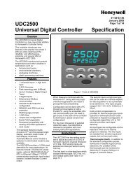
<strong>HC900</strong> C30/C50<br />
CPU Assembly<br />
RS232<br />
RS485<br />
Ethernet<br />
I/O<br />
<strong>HC900</strong> C70R<br />
CPU Assembly<br />
S2<br />
E1<br />
E2<br />
I/O<br />
S1<br />
Network connection is via the controller<br />
host Ethernet 10Base-T port using<br />
Modbus/TCP protocol. A variety of<br />
Windows operating environments are<br />
supported including Windows 98, NT,<br />
2000, and XP.<br />
OPC Server–Network communication<br />
access to <strong>HC900</strong> controllers through<br />
third party PC interfaces is simplified<br />
with <strong>Honeywell</strong>’s OPC server software<br />
program. This software supports the<br />
Modbus/TCP interface to either<br />
redundant or non-redundant <strong>HC900</strong><br />
controllers. In redundant applications,<br />
<strong>Honeywell</strong>’s OPC Server software<br />
supports dual redundant Ethernet<br />
connections to both C70R CPUs.<br />
Communications to the controller is<br />
maintained during a single network<br />
failure and/or following the transfer of<br />
the Lead function from one CPU to<br />
another. Compatible OPC client<br />
programs can use the Ethernet<br />
connection to the <strong>HC900</strong> via<br />
<strong>Honeywell</strong>’s OPC Server for remote<br />
supervision, data collection or other<br />
supervisory functions.<br />
Configuration port for direct or<br />
external modem connection, 9-pin D<br />
Interface to 1042 Operator Interface,<br />
3-pin<br />
Ethernet 10/100Base-T for<br />
host, peer and LAN connection<br />
Ethernet 10Base-T for I/O<br />
rack connection (C50 only)<br />
Ports S1 & S2 user-selectable<br />
type. Operator Interface and/or<br />
Configuration port for direct or<br />
external modem connection.<br />
Ethernet 10/100Base-T for<br />
host and LAN connection<br />
Ethernet 10/100Base-T for<br />
host and LAN connection<br />
Ethernet 100Base-T for<br />
I/O rack connection<br />
Figure 1 Communication ports
51-52-03-31<br />
Page 10<br />
Specifications<br />
<strong>Controller</strong> Design<br />
C30 C50 C70R<br />
Modular design with metal rack enclosure, power supply, controller CPU and user selectable<br />
I/O module types.<br />
Surface mounting with 4 screws in back of rack.<br />
Installation Category II, Pollution Degree 2, IEC 664, UL840 Installation coordination<br />
4, 8, or 12 I/O slots per Rack None (requires remote I/O<br />
racks)<br />
1 w/o hub, using Ethernet<br />
direct cable.<br />
Up to 5 with recommended<br />
Ethernet switching hub(s).<br />
Rack Mounting and<br />
Installation<br />
<strong>Controller</strong> I/O<br />
support<br />
Remote I/O racks None 1 w/o hub, using Ethernet<br />
direct cable.<br />
Up to 4 with recommended<br />
Ethernet hub(s).<br />
Remote I/O interface<br />
type<br />
None<br />
Separate Ethernet 10Base-T<br />
port on CPU, RJ-45<br />
connection, dedicated<br />
communications link<br />
Separate Ethernet 100Base-<br />
T port on CPU, RJ-45<br />
connection, dedicated<br />
communications link<br />
Remote I/O Distance None 328 ft. (100 m.) – controller to remote rack or controller to<br />
hub. Up to two hubs per connection, 984 ft. (300 m.),<br />
maximum distance.<br />
I/O Capacity<br />
Combined Analog and<br />
Digital<br />
192 960<br />
Analog Inputs 96 256<br />
Analog Outputs 64 64<br />
Rack Size<br />
4 I/O slot chassis 5.4”(137mm) H” x 10.5”(266.7mm) W x 6” (151.7 mm) D (rear mounting plate extends height<br />
to 6.9” (175.3mm)<br />
8 I/O slot chassis 5.4”(137mm) H x 16.5”(419.1mm) W x 6” (151.7mm) D (rear mounting plate extends height to<br />
6.9” (175.3mm)<br />
8 I/O slot chassis with<br />
redundant power<br />
support<br />
5.4”(137mm) H x 20.9”(530.9.1mm) W x 6” (151.7mm) D (rear mounting plate extends height<br />
to 6.9” (175.3mm)<br />
12 I/O slot chassis 5.4”(137mm) H x 22.5”(571.5mm) W x 6.”(151.7mm) D (rear mounting plate extends height to<br />
6.9” (175.3mm)<br />
12 I/O slot chassis with 5.4”(137mm) H x 26.9”(683.3mm) W x 6.”(151.7mm) D (rear mounting plate extends height to<br />
redundant power 6.9” (175.3mm)<br />
support<br />
I/O Wiring<br />
Type<br />
Terminal Block Styles<br />
Gauge wires<br />
Shield terminals<br />
Power (P01)<br />
Voltage<br />
In Rush Current<br />
Power wiring<br />
Fuse<br />
Power (P02)<br />
Voltage<br />
In Rush Current<br />
Power wiring<br />
Fuse<br />
Normal Scan Time<br />
CPU rack N/A N/A 5.4”(137mm) H x<br />
10.3”(261.6mm) W x<br />
6” (151.7mm) D<br />
(rear mounting plate extends<br />
height to 6.9” (175.3mm)<br />
Removable terminal blocks<br />
2, Screw terminal or Euro-style, tin-plated or gold-plated (for DC connections)<br />
Screw terminal – #14 to 26 AWG, solid or stranded<br />
Euro-style - #14 to 26 AWG, solid or stranded<br />
Optional brackets mounted top/bottom of rack<br />
Universal power, 90 to 264VAC, 47 to 63 Hz<br />
7 Amps peak-to-peak for 150 ms at 240VAC<br />
130 VA<br />
Internally mounted, non-replaceable fuse. User installed external fuse.<br />
Universal power, 90 to 264VAC, 47 to 63 Hz<br />
7 Amps peak-to-peak for 120 ms at 240VAC<br />
90 VA<br />
Internally mounted, non-replaceable fuse. User installed external fuse.<br />
500ms. Each analog input card has its own A/D converter providing parallel processing.
51-52-03-31<br />
Page 11<br />
Specifications<br />
Fast Scan Time<br />
Detection+Failover<br />
time from Lead to<br />
Reserve CPU<br />
Run-Mode Edit<br />
Transfer Time<br />
Operating Modes<br />
C30 C50 C70R<br />
53ms for up to~250 fast logic<br />
blocks<br />
67ms for up to ~315 fast logic<br />
blocks<br />
107ms for up to ~400 fast logic<br />
blocks<br />
27ms for up to ~250 fast logic<br />
blocks<br />
53ms for up to~500 fast logic<br />
blocks<br />
67ms for up to ~780 fast logic<br />
blocks<br />
107ms for up to ~1040 fast logic<br />
blocks<br />
133ms for up to ~1300 fast logic<br />
blocks<br />
53ms for up to~500 fast logic<br />
blocks<br />
67ms for up to ~780 fast logic<br />
blocks<br />
107ms for up to ~1040 fast logic<br />
blocks<br />
133ms for up to ~1300 fast logic<br />
blocks<br />
267ms for up to~2500 fast logic<br />
blocks<br />
N/a N/a Up to 4 analog scan cycles<br />
3 normal scan times (1.5 sec. typical) for all configuration edits not applicable to I/O<br />
Run (No configuration download in this position)<br />
Run/Program (Download allowed)<br />
Program (Outputs Off, initialization on download).<br />
Offline mode is available via software selection (for AI calibration).<br />
Specifications<br />
Maximum userconfigurable<br />
Function<br />
Blocks<br />
Features<br />
C30 C50 C70R<br />
400 2000 5000<br />
Maximum Control Loops 8 32 32<br />
System Blocks (Not user<br />
configurable)<br />
100 (not part of 400, 2000 or 5000), for Alarm Group blocks, System block, Rack<br />
Monitor blocks, Communications<br />
Loop Outputs<br />
Current, time proportional, position proportional, 3-position step (motor positioning),<br />
dual output [heat/cool])<br />
Control Loop Types<br />
PID A, PID B, Duplex A, Duplex B, Ratio, Cascade, % Carbon, Dewpoint, Relative<br />
Humidity, On-Off, Auto/Manual-Bias<br />
Auto-tuning<br />
Accutune II, fuzzy logic overshoot suppression, applicable to all control loops<br />
Setpoint Programmers<br />
Programmer Events<br />
Setpoint Profiles<br />
8 (independent programmers)<br />
Ramp Types: Ramp Rate or Ramp Time<br />
Time Units: Hours or Minutes<br />
Segment Time: 0-99,999.999 hours or minutes<br />
Program Cycles: Up to 100 or infinite, configurable segment range<br />
16, assignable to DO or internal status<br />
99 profiles of 50 segments each stored in controller<br />
Setpoint Scheduler Two (2)<br />
Ramp type: Ramp time<br />
Time units: Hours or minutes<br />
Segment time: 0.001 to 9999.999 hours or minutes<br />
Cycles: Per segment to 999 or infinite<br />
Auxiliary Scheduler<br />
Up to 8 setpoints, soak only<br />
Setpoints<br />
Schedule events<br />
Up to 16, assignable to DO or internal status<br />
Setpoint Scheduler<br />
Schedules<br />
20 Schedules stored in controller, 50 segments each
51-52-03-31<br />
Page 12<br />
Specifications<br />
Features<br />
C30 C50 C70R<br />
Sequencers Four (4)<br />
States: 50<br />
State text: 12 characters<br />
Steps: 64<br />
Time Units: Minutes or Seconds<br />
Digital Outputs: 16<br />
Analog Output: 1, configurable value/step<br />
Step Execution: On Time, Event 1, Event2, or via Advance<br />
Next Step: Any step<br />
Sequences<br />
20 sequences stored in controller<br />
Recipes (Variables)<br />
50 stored in controller<br />
Recipe Parameters<br />
Up to 50 analog or digital Variables — (may include profile numbers)<br />
Signal Tags (Read only) 2000 Tags<br />
Tag Identification<br />
8-character tagname, 16-character descriptor,4-character units of measure (analog<br />
only), 6 character on/off state (digital only)<br />
Variables (Read/Write) 600<br />
Variable Identification 8-character tagname, 16-character descriptor,4-character units of measure (analog<br />
only), 6 character on/off state (digital only)<br />
Specifications<br />
Network Communications<br />
Ports<br />
Ethernet 10/Base-T, RJ-45<br />
connection<br />
Two Ethernet 10/100Base-T,<br />
RJ-45 connections<br />
Max. number of concurrent<br />
Ethernet host connections<br />
RS-232 Ports<br />
Ports per controller<br />
Baud rates<br />
Modem<br />
Communications<br />
C30 C50 C70R<br />
Supports Modbus/TCP Protocol to PC supervisory and<br />
data acquisition software packages, OPC server, and<br />
<strong>Hybrid</strong> Control Designer configuration software<br />
Up to 5 (peer data exchange does not consume a host<br />
connection)<br />
One, 9-pin “D”, <strong>Honeywell</strong> or Modbus RTU protocol.<br />
Supports link to PC running <strong>Hybrid</strong> Control Designer<br />
software or third party applications.<br />
Lead CPU supports<br />
redundant Modbus/TCP<br />
Protocol to OPC server, PC<br />
supervisory and data<br />
acquisition software<br />
packages and <strong>Hybrid</strong><br />
Control Designer<br />
configuration software.<br />
Up to 10 shared between<br />
two ports (peer data<br />
exchange does not<br />
consume a host<br />
connection).<br />
Two, user selectable<br />
between RS 232 and RS-<br />
485 with Modbus RTU or<br />
<strong>Honeywell</strong> protocol. 3-Plug<br />
connectors supplied.<br />
9600, 19.2K, 38.4K, 57.6 K, configured by <strong>Hybrid</strong> Control Designer software or OI.<br />
For remote connection to <strong>Hybrid</strong> Control Designer software, requires external modem<br />
at controller, 9600 baud to 57.6KB
51-52-03-31<br />
Page 13<br />
Specifications<br />
RS-485 Ports<br />
Ports per controller<br />
Communications<br />
C30 C50 C70R<br />
One, RS-485 (connector supplied), <strong>Honeywell</strong> or<br />
Modbus RTU protocol, 1042, 559, or third party operator<br />
interface support<br />
Cable type 2-wire plus shield, Belden 9271 or equivalent<br />
1042, 559 Distance from 2000 ft. (600 m.)<br />
controller<br />
1042, 559 Power to OI 24VDC, user-provided at OI<br />
Unit addresses 1 to 247<br />
RS-232, RS-485 Ports<br />
Parity (user selectable) Odd, even, none<br />
Stop bits (user selectable) 1 or 2<br />
Speed (user selectable) 9600, 19200, 38400, 57600<br />
Double Register Format for<br />
Modbus RTU Slave and<br />
Master data (User selectable)<br />
RS-232, RS-485 Modbus<br />
Slave Operation<br />
Number of ports per controller<br />
Masters per port<br />
User Specified Register<br />
Address Array<br />
Principal Function Block<br />
Address Range<br />
RS-232, RS-485 Modbus<br />
Master Operation<br />
Number of ports per controller<br />
Function Block Types<br />
FPB – Big Endian- (0,1,2,3)<br />
FP LB – Little Endian Byte Swap (2,3,0,1)<br />
FP BB – Big Endian Byte Swap (1,0,3,2)<br />
FPL – Little Endian (3,2,1,0)<br />
Two, user selectable<br />
between RS-485 and RS-<br />
232 (connector supplied),<br />
<strong>Honeywell</strong> or Modbus RTU<br />
protocol. Only one port for<br />
1042/ 559 operator<br />
interface support.<br />
Up to two<br />
One<br />
1000 register addresses (45057 to 46056 decimal)<br />
Data Types; Unsigned 16, Signed 16, Unsigned 32, Signed 32, Float 32<br />
User selectable starting address range for registers assigned to each principal block<br />
type.<br />
One (RS232 or RS485)<br />
Slave – 4 read and 4 write data points<br />
Read (Slave extension block ) up to 16 parameters<br />
Write (Slave extension) up to 8 parameters<br />
(No limit on the number of Read and Write extension blocks per Slave block up to the<br />
maximum 384 parameters per controller.)<br />
Slave devices per controller Up to 16<br />
Number of read/write Modbus Up to 384 max. per controller<br />
Parameters<br />
Double Register Format Selectable per device<br />
Speed 1 second max. – load dependent<br />
Peer-to-peer<br />
Ethernet 10Base-T<br />
10/100Base-T via Network<br />
port<br />
Supports UDP protocol and Peer Data Exchange<br />
function blocks for peer data exchange.<br />
No. of Peers/<strong>Controller</strong> 8<br />
Update rate 500 ms to 5 sec., selectable<br />
Peer Data<br />
Supports UDP protocol and<br />
Peer Data Exchange<br />
function blocks for peer<br />
data exchange.<br />
Digital and Analog Signal Tags, Variables - up to 1024 parameters, addressed<br />
numerically<br />
Ethernet<br />
Ethernet Network Connection 10 Base-T, RJ-45 (10 Mbits/sec.) 10/100 Base-T, RJ-45<br />
Host Network Protocol Modbus/TCP
51-52-03-31<br />
Page 14<br />
Maximum distances per Ethernet specifications<br />
C70R CPU to I/O Rack Ethernet CAT5 cable with RJ-45 connectors 100m /328 ft<br />
C70R to Ethernet Switch Ethernet CAT5 cable with RJ-45 connectors 100m /328 ft<br />
Ethernet Switch to I/O Rack Ethernet CAT5 cable with RJ-45 connectors 100m /328 ft<br />
C70R CPU to Network Switch Ethernet CAT5 cable with RJ-45 connectors 100m /328 ft<br />
Network Switch to PC Ethernet CAT5 cable with RJ-45 connectors 100m /328 ft<br />
C70R to 1042 Operator Interface Shielded, Twisted pair 610m /2000 ft<br />
Approvals<br />
CE Conformity This product is in conformity with the protection requirements of the following European<br />
Council Directives: 73/23/EEC, the Low Voltage Directive, and 89/336/EEC, the EMC<br />
Directive. Conformity of this product with any other “CE Mark” Directive(s) shall not be<br />
assumed. EN61326: Electrical Equipment For Measurement, Control and Laboratory use.<br />
EMC requirements.<br />
General Purpose Compliant with EN61010-1, UL, UL 3121-1, CSA C22.2 No. 1010-1<br />
Safety<br />
Hazardous<br />
(Classified) Location<br />
Safety<br />
FM Class I, Div. 2, Groups A, B, C, D<br />
CSA Class I, Div. 2 Groups A, B, C, D<br />
Class 1, Zone 2, IIC<br />
Module “T” ratings Module Type “T” Rating<br />
Rack (4, 8, 12 I/O slots)<br />
T6<br />
Power Supply<br />
T4<br />
Power Status Module (PSM)<br />
T6<br />
<strong>Controller</strong> C30 CPU<br />
T5<br />
<strong>Controller</strong> C50CPU<br />
T5<br />
I/O Scanner 1<br />
T5<br />
<strong>Controller</strong> C70R CPU<br />
T4<br />
Redundancy Switch Module (RSM)<br />
T6<br />
I/O Scanner 2<br />
T5<br />
Ambient<br />
Temperature<br />
F<br />
C<br />
Ambient Relative<br />
Humidity<br />
Mechanical<br />
Acceleration<br />
Duration<br />
Vibration<br />
* Applies up to 40C<br />
Environmental Conditions<br />
Reference Rated Extreme Transportation & Storage<br />
77+/-5<br />
25+/-3<br />
*45 % to 55 % RH<br />
non-condensing<br />
0 g<br />
0 ms<br />
0 Hz<br />
0 g<br />
32 to 140<br />
0 to 60<br />
*10% to 90 % RH<br />
non-condensing<br />
1 g<br />
30 ms<br />
0 Hz to 14 Hz—<br />
amplitude 2.5 mm<br />
(peak-to-peak)<br />
14 Hz to 250 Hz—<br />
acceleration 1 g<br />
32 to 140<br />
0 to 60<br />
*5 % to 90 % RH<br />
non- condensing<br />
1 g<br />
30 ms<br />
0 Hz to 14 Hz—<br />
amplitude 2.5 mm<br />
(peak-to-peak)<br />
14 Hz to 250 Hz—<br />
acceleration 1 g<br />
-40 to 158<br />
-40 to 70<br />
*5 % to 95 % RH<br />
non-condensing<br />
Not rated
51-52-03-31<br />
Page 15<br />
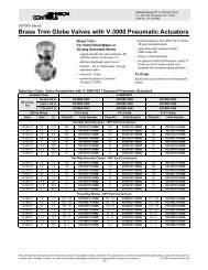
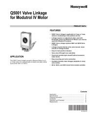
Dimensions<br />
10.5<br />
266.7<br />
16.5<br />
419.1<br />
4 Slots<br />
5.4*<br />
137<br />
6.0**<br />
152.4<br />
8 Slots<br />
5.4*<br />
137<br />
6.0**<br />
152.4<br />
22.5<br />
571.5<br />
12 Slots<br />
5.4*<br />
137<br />
6.0**<br />
152.4<br />
10.3<br />
261.6<br />
Redundant<br />
CPU<br />
5.4*<br />
137<br />
6.0**<br />
152.4<br />
Key:<br />
In<br />
mm<br />
* 6.9 with mounting flanges<br />
175<br />
**Total depth (rack + components)<br />
20.9<br />
530.9<br />
8 Slots<br />
Redundant Power Supply<br />
5.4*<br />
137<br />
6.0**<br />
152.4<br />
26.9<br />
684.0<br />
12 Slots<br />
Redundant Power Supply<br />
5.4*<br />
137<br />
6.0**<br />
152.4<br />
Figure 2 <strong>HC900</strong> <strong>Hybrid</strong> <strong>Controller</strong> Dimensions
51-52-03-31<br />
Page 16<br />
Warranty/Remedy<br />
<strong>Honeywell</strong> warrants goods of its manufacture as being free of defective materials and faulty workmanship.<br />
Contact your local sales office for warranty information. If warranted goods are returned to <strong>Honeywell</strong> during<br />
the period of coverage, <strong>Honeywell</strong> will repair or replace without charge those items it finds defective. The<br />
foregoing is Buyer's sole remedy and is in lieu of all other warranties, expressed or implied, including<br />
those of merchantability and fitness for a particular purpose. Specifications may change without notice.<br />
The information we supply is believed to be accurate and reliable as of this printing. However, we assume no<br />
responsibility for its use.<br />
While we provide application assistance personally, through our literature and the <strong>Honeywell</strong> web site, it is up<br />
to the customer to determine the suitability of the product in the application.<br />
Distributor :<br />
For more information, contact <strong>Honeywell</strong> sales at:<br />
US: 1-800-343-0228<br />
Canada: 1-800-461-0013<br />
<strong>Industrial</strong> Measurement and Control<br />
<strong>Honeywell</strong><br />
1100 Virginia Drive<br />
Fort Washington, PA 19034<br />
51-52-03-31 04-06-05 Printed in USA www.honeywell.com/imc/
51-51-16U-70<br />
Issue 20<br />
Page 1 of 4<br />
<strong>HC900</strong> <strong>Hybrid</strong> <strong>Controller</strong><br />
Assemblies<br />
Model Selection Guide<br />
RACKS MODEL NUMBER<br />
4 I/O Slot Rack<br />
8 I/O Slot Rack<br />
12 I/O Slot Rack<br />
8 Slot Rack -Red. Power<br />
12 Slot Rack - Red. Power<br />
Redundant Power Status Module<br />
900R04 - 0001<br />
900R08 - 0101<br />
900R12 - 0101<br />
900R08R - 0101<br />
900R12R - 0101<br />
900PSM - 0001<br />
Power Supplies<br />
120/240VAC, 60W<br />
120/240VAC, 28W Note 5<br />
900P01 -0001<br />
900P02 -0001<br />
24Vdc, 60W<br />
CPU Assemblies<br />
<strong>Controller</strong> C70 CPU Config. SW & Docs<br />
<strong>Controller</strong> C70 CPU Note 1<br />
900P24 -0001<br />
900C71 - 0144-00<br />
900C72 - 0144-00<br />
<strong>Controller</strong> C50 CPU Config.SW & Docs<br />
<strong>Controller</strong> C50 CPU Note 1<br />
900C51 - 0244-00<br />
900C52 - 0244-00<br />
<strong>Controller</strong> C30 CPU Config. SW & Docs<br />
<strong>Controller</strong> C30 CPU Note 1<br />
900C31 - 0244-00<br />
900C32 - 0244-00<br />
I/O Scanner (for remote rack)<br />
I/O Card Selections<br />
Analog Input (8 channel)<br />
Analog Input Hi level (16ch)<br />
Analog Output, 0 to 20mA, (4 channel)<br />
Analog Output, 0 to 20mA, (8 channel)<br />
Analog Output, 0 to 20mA, (16 channel)<br />
Digital Input, Contact type, (16 channel)<br />
Digital Input, 24VDC (16 channel)<br />
Digital Input, 120/240 VAC, (16 channel)<br />
Digital Input, 24VDC (32 channel)<br />
Digital Output, Relays ( 8 channel)<br />
Digital Output, 24VDC (16 channel)<br />
Digital Output, 120/240 VAC (8 channel)<br />
Digital Output, 24VDC (32 channel)<br />
Pulse/Freq/Quad (4chan, 1Quad)<br />
900C53 - 0244-00<br />
900A01 - 0102<br />
900A16 - 0001<br />
900B01 -0101<br />
900B08-0001<br />
900B16-0001<br />
900G01 - 0102<br />
900G02 - 0102<br />
900G03 - 0102<br />
900G32 - 0001<br />
900H01 - 0102<br />
900H02 - 0102<br />
900H03 - 0102<br />
900H32 - 0001<br />
900K01 - 0001
51-51-16U-70<br />
Issue 20<br />
Page 2 of 4<br />
Terminal Blocks, Cables, Jumpers<br />
Low VoltageTerminal Block (Euro style) Note 3<br />
Low VoltageTerminal Block (Barrier Style) Note 3<br />
High VoltageTerminal Block (Euro style) Note 3<br />
High Voltage Terminal Block (Barrier Style) Note 3<br />
Low voltage Terminal Block (36 pos) Note 3<br />
Analog Input Remote Terminal Panel (RTP) Note 6<br />
Relay Output Remote Terminal Panel (RTP) Note 6<br />
DI, DO, AO Remote Terminal Panel (RTP) Note 6<br />
Low Voltage RTP Cable (1.0M, 3.28ft.) Note 6<br />
Low Voltage RTP Cable (2.5M, 8.2ft.) Note 6<br />
Low Votage RTP Cable (5.0M, 16.4ft.) Note 6<br />
High Voltage RTP Cable (1.0M, 3.28ft.) Note 6<br />
High Voltage RTP Cable (2.5M, 8.2ft.) Note 6<br />
High Votage RTP Cable (5.0M, 16.4ft.) Note 6<br />
LV RTP Cable (32/16 channel) (1.0M, 3.28ft) Note 6<br />
LV RTP Cable (32/16 channel) (2.5M, 8.2ft) Note 6<br />
LV RTP Cable (32/16 channel) (5.0M, 16.4ft) Note 6<br />
8 ch A/O RTP Cable (1M, 3.3ft) Note 6<br />
8 ch A/O RTP Cable (2.5M, 8.2ft) Note 6<br />
8 ch A/O RTP Cable (5.0M, 16.4ft) Note 6<br />
Filler Block Terminal Cover<br />
Shield Terminal Strip (package of 2)<br />
Terminal board jumpers (10, two pos jumpers) Note 4<br />
Terminal board jumpers (10, ten pos.jumpers) Note 4<br />
Manuals<br />
Full document set on CD Note 2<br />
Full document set, hard copy - Engish Note 2<br />
Software<br />
HC Designer Config. Software CD<br />
HC Utilities Software/Documentation CD<br />
HC Historian Software<br />
MODEL NUMBER<br />
900TEK - 0001<br />
900TBK -0001<br />
900TER - 0001<br />
900TBR - 0001<br />
900TCK - 0001<br />
900RTA - L001<br />
900RTR - H001<br />
900RTS - 0001<br />
900RTC - L010<br />
900RTC - L025<br />
900RTC - L050<br />
900RTC - H010<br />
900RTC - H025<br />
900RTC - H050<br />
900RTC - 3210<br />
900RTC - 3225<br />
900RTC - 3250<br />
900RTC-B810<br />
900RTC-B825<br />
900RTC-B850<br />
900TNF - 0001<br />
900TSS - 0001<br />
900J02 - 0001<br />
900J10 - 0001<br />
900ME1-0044-44<br />
900ME2-0044-44<br />
900W01-0044-44<br />
900W02-0044-44<br />
50045756-001<br />
Note 1: Documentation and <strong>Hybrid</strong> Control Designer Configuration Software are not provided with<br />
this model. If required, specify CPU model numbers 900C71-NNNN-NN, 900C51-0NNN-NN,<br />
900C31-0NNN-NN or order items separately.<br />
Note 2: A full documentation set on CD is provided with CPU 900C51-00NN-NN and 900C31-00NN-<br />
NN. If additional copies or if a hard copy manual set is desired, specify them as separate items. The<br />
manual set contains one each of all <strong>HC900</strong> product manuals. Doc<br />
Note 3: Terminal blocks for I/O modules must be ordered separately. Two styles are available for<br />
each of the two types--Euro style and Barrier style. The type of terminal block (gold and tin contacts)<br />
must be matched to the appropriate I/P board type. S<br />
Card Type<br />
Terminal Blocks<br />
Analog Input (8 channel)<br />
900TEK-0001<br />
Analog Output, 0 to 20mA, (4 channel)<br />
900TEK-0001<br />
Analog Output, 0 to 20mA, (8 channel)<br />
900TCK - 0001<br />
Analog Output, 0 to 20mA, (16 channel)<br />
900TCK - 0001<br />
Digital Input, Contact type, (16 channel)<br />
900TEK-0001<br />
Digital Input, 24VDC (16 channel)<br />
900TEK-0001<br />
Digital Input, 120/240 VAC, (16 channel)<br />
900TER-0001<br />
Digital Output, Relays ( 8 channel)<br />
900TER-0001<br />
Digital Output, 24VDC (16 Channel)<br />
900TEK-0001<br />
Digital Output, 120/240 VAC (8 channel)<br />
900TER-0001<br />
Note 4: Jumpers available for Barrier Style terminals only.<br />
900TBK-0001<br />
900TBK-0001<br />
900TBK-0001<br />
900TBK-0001<br />
900TBR-0001<br />
900TBR-0001<br />
900TBK-0001<br />
900TBR-0001
Note 5: How to choose an AC Power Supply<br />
51-51-16U-70<br />
Issue 20<br />
Page 3 of 4
51-51-16U-70<br />
Issue 20<br />
Page 4 of 4<br />
Note 6<br />
Using the table below, select a Remote Terminal Panel and Cable Assembly to match the module type.<br />
Module Types Module Model Remote Terminal<br />
Panel<br />
Acceptable<br />
Cables<br />
Analog Input Module 900A01 – 010X 900RTA – L001 900RTC – L010<br />
900RTC – L025<br />
900RTC – L050<br />
Relay Output Module 900H01 – 010X 900RTR – H001 900 RTC – H010<br />
900 RTC – H025<br />
900 RTC – H050<br />
Analog Output Module<br />
Contact Discrete Input Module<br />
DC Discrete Input Module<br />
DC Discrete Output Module<br />
AC Discrete Input Module<br />
AC Discrete Output Module<br />
Digital Input , 32 channel<br />
Digital Output, 32 Channel<br />
Analog Input, 16 Channel<br />
900B01 – 010X<br />
900G01 – 010X<br />
900G02 – 010X<br />
900H02 – 010X<br />
900G03 - 010X<br />
900H03 – 010X<br />
900G32-000X<br />
900H32-000X<br />
900A16-000X<br />
900RTS - 0001<br />
900RTS - 0001<br />
900RTS - 0001<br />
(2 required)<br />
900RTC – L010<br />
900RTC – L025<br />
900RTC – L050<br />
900 RTC – H010<br />
900 RTC – H025<br />
900 RTC – H050<br />
900RTC – 3225<br />
900RTC – 3210<br />
900RTC - 3250<br />
Analog Output Module 8<br />
Channel<br />
Analog Output Module 16<br />
Channel<br />
900B08-0001 900RTS - 0001 900RTC – B810<br />
900RTC – B825<br />
900RTC – B850<br />
900B16-0001 900RTS – 0001<br />
(2 required)<br />
900RTC – 3225<br />
900RTC – 3210<br />
900RTC - 3250