The Discontinuous Weld Bead Defect in High-Speed Gas Metal Arc ...
The Discontinuous Weld Bead Defect in High-Speed Gas Metal Arc ...
The Discontinuous Weld Bead Defect in High-Speed Gas Metal Arc ...

Create successful ePaper yourself
Turn your PDF publications into a flip-book with our unique Google optimized e-Paper software.
WELDING RESEARCH<br />
<strong>The</strong> <strong>Discont<strong>in</strong>uous</strong> <strong>Weld</strong> <strong>Bead</strong> <strong>Defect</strong> <strong>in</strong><br />
<strong>High</strong>-<strong>Speed</strong> <strong>Gas</strong> <strong>Metal</strong> <strong>Arc</strong> <strong>Weld</strong>s<br />
A new type of high-speed gas metal arc weld bead defect<br />
was observed and characterized<br />
BY T. C. NGUYEN, D. C. WECKMAN, AND D. A. JOHNSON<br />
ABSTRACT. A common weld bead defect<br />
that occurs at high fusion weld<strong>in</strong>g speeds<br />
is the periodic undulation of the weld bead<br />
profile, also known as hump<strong>in</strong>g. In the<br />
present study, when us<strong>in</strong>g argon shield<strong>in</strong>g<br />
gas, 0.9-mm-diameter ER70S-6 and<br />
ER70S-3 electrode wires, and weld<strong>in</strong>g<br />
powers between 9 and 12 kW dur<strong>in</strong>g highspeed<br />
gas metal arc weld<strong>in</strong>g of SAE-AISI<br />
1018 cold rolled steel plate, sw<strong>in</strong>g<strong>in</strong>g spray<br />
metal transfer was observed and the weld<strong>in</strong>g<br />
speed was found to be limited to 15<br />
mm/s by the onset of the periodic hump<strong>in</strong>g<br />
phenomenon. However, rotational<br />
metal transfer was observed when us<strong>in</strong>g<br />
reactive shield<strong>in</strong>g gases at these powers<br />
and the weld<strong>in</strong>g speed was limited to<br />
22 mm/s by the onset of a new, as yet unreported,<br />
weld defect that was dist<strong>in</strong>ctly<br />
different from hump<strong>in</strong>g. This new highspeed<br />
defect is referred to as the discont<strong>in</strong>uous<br />
weld bead defect, s<strong>in</strong>ce the defective<br />
weld bead is broken up <strong>in</strong>to several<br />
good bead segments by aperiodic or irregularly<br />
spaced valleys or depressions where<br />
melt<strong>in</strong>g of the base metal occurred but no<br />
filler metal was deposited. <strong>The</strong> results also<br />
<strong>in</strong>dicated that nom<strong>in</strong>al electrode wire<br />
composition did not appear to play a significant<br />
role <strong>in</strong> the formation of the hump<strong>in</strong>g<br />
or the discont<strong>in</strong>uous weld bead<br />
defects.<br />
A LaserStrobe video imag<strong>in</strong>g system<br />
was used to obta<strong>in</strong> video images of typical<br />
sequences of events dur<strong>in</strong>g the formation<br />
of the hump<strong>in</strong>g and discont<strong>in</strong>uous weld<br />
bead defects. From these images, the discont<strong>in</strong>uous<br />
weld bead defect was found to<br />
be caused by the <strong>in</strong>consistent, aperiodic<br />
deposition of molten filler metal dur<strong>in</strong>g<br />
rotational filler metal transfer mode when<br />
us<strong>in</strong>g reactive shield<strong>in</strong>g gases. <strong>The</strong> long<br />
molten filler metal str<strong>in</strong>g on the end of the<br />
electrode wire was erratically fragmented<br />
T. C. NGUYEN was with the University of Waterloo.<br />
He is now at the School of Eng<strong>in</strong>eer<strong>in</strong>g and<br />
Information Technology, Conestoga College,<br />
Kitchener, Ont., Canada. D. C. WECKMAN and<br />
D. A. JOHNSON are with the Department of Mechanical<br />
Eng<strong>in</strong>eer<strong>in</strong>g, University of Waterloo, Waterloo,<br />
Ont., Canada.<br />
and required time to re-form prior to the<br />
resumption of the transfer of filler metal.<br />
<strong>The</strong> temporary disruption of filler metal<br />
deposition created a filler-metal-free depression<br />
that broke up the otherwise good<br />
weld bead, thereby form<strong>in</strong>g the discont<strong>in</strong>uous<br />
weld bead defect. <strong>The</strong> irregular fragmentation<br />
of the molten filler metal str<strong>in</strong>g<br />
dur<strong>in</strong>g rotational transfer and subsequent<br />
formation of the aperiodic discont<strong>in</strong>uous<br />
weld bead defect are phenomena that<br />
have not previously been observed or reported<br />
<strong>in</strong> the open literature.<br />
Introduction<br />
<strong>Weld</strong><strong>in</strong>g is a ubiquitous process and an<br />
<strong>in</strong>tegral part of most manufactur<strong>in</strong>g <strong>in</strong>dustries<br />
such as the construction, shipbuild<strong>in</strong>g,<br />
aerospace, automotive, petrochemical,<br />
and electronics <strong>in</strong>dustries. To<br />
rema<strong>in</strong> competitive <strong>in</strong> today’s manufactur<strong>in</strong>g<br />
environment, companies must cont<strong>in</strong>uously<br />
improve their productivity without<br />
sacrific<strong>in</strong>g the quality of their<br />
products. Increases <strong>in</strong> productivity will reduce<br />
overall production costs, thereby<br />
ma<strong>in</strong>ta<strong>in</strong><strong>in</strong>g and strengthen<strong>in</strong>g the company’s<br />
competitiveness. Overall production<br />
costs can usually be reduced by evaluat<strong>in</strong>g<br />
the productivity of the weld<strong>in</strong>g<br />
processes used. For many welded products,<br />
an <strong>in</strong>crease <strong>in</strong> productivity often requires<br />
use of higher weld<strong>in</strong>g speeds. Frequently,<br />
this can be achieved through<br />
optimiz<strong>in</strong>g or automat<strong>in</strong>g exist<strong>in</strong>g weld<strong>in</strong>g<br />
processes. In certa<strong>in</strong> cases, switch<strong>in</strong>g to<br />
newer high-energy-density weld<strong>in</strong>g<br />
processes will also result <strong>in</strong> higher weld<strong>in</strong>g<br />
KEYWORDS<br />
<strong>Gas</strong> <strong>Metal</strong> <strong>Arc</strong> <strong>Weld</strong><strong>in</strong>g<br />
Hump<strong>in</strong>g<br />
<strong>Weld</strong> <strong>Defect</strong>s<br />
Argon Shield<strong>in</strong>g <strong>Gas</strong><br />
Reactive Shield<strong>in</strong>g <strong>Gas</strong>es<br />
<strong>Discont<strong>in</strong>uous</strong> <strong>Weld</strong> <strong>Bead</strong>s<br />
Carbon Steel<br />
speeds and <strong>in</strong>creases <strong>in</strong> productivity.<br />
In order to weld at higher weld<strong>in</strong>g<br />
speeds, the heat <strong>in</strong>put of all fusion weld<strong>in</strong>g<br />
processes must be <strong>in</strong>creased to ma<strong>in</strong>ta<strong>in</strong><br />
the same amount of energy <strong>in</strong>put per unit<br />
length of weld required for melt<strong>in</strong>g of<br />
filler and base metals (Refs. 1–3), otherwise,<br />
the weld cross section will decrease<br />
and eventually no melt<strong>in</strong>g of the base<br />
metal will occur. While <strong>in</strong>creas<strong>in</strong>g weld<strong>in</strong>g<br />
speed and heat <strong>in</strong>put will provide the desired<br />
productivity <strong>in</strong>crease, cont<strong>in</strong>ued <strong>in</strong>creases<br />
of the weld<strong>in</strong>g speed is <strong>in</strong> practice<br />
limited by the deterioration of the quality<br />
of weld bead profile. One of the most commonly<br />
occurr<strong>in</strong>g geometric defects that<br />
has been observed at high weld<strong>in</strong>g speeds<br />
is the hump<strong>in</strong>g phenomenon (Refs. 4–6).<br />
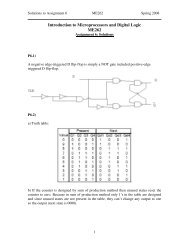
An example of a humped gas metal arc<br />
(GMA) weld bead is shown <strong>in</strong> Fig. 1.<br />
Hump<strong>in</strong>g can be described as a periodic<br />
undulation of the weld bead with regularly<br />
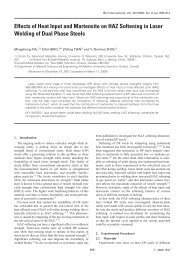
spaced humps and valleys. Figure 2 shows<br />
transverse sections at a valley and a hump,<br />
respectively, of the humped GMA weld<br />
bead <strong>in</strong> Fig. 1. Although the depth of penetration<br />
is the same for both transverse<br />
sections, there is more weld metal accumulation<br />
at the hump. <strong>The</strong> hump<strong>in</strong>g defect<br />
compromises the mechanical <strong>in</strong>tegrity<br />
of the weld jo<strong>in</strong>t, thereby limit<strong>in</strong>g the<br />
weld<strong>in</strong>g speed and thus overall production<br />
rates.<br />
Nguyen et al. (Ref. 5) and Soderstrom<br />
and Mendez (Ref. 6) have recently reviewed<br />
the literature related to high-speed<br />
fusion weld bead defects, their causes, and<br />
techniques that have been used to <strong>in</strong>crease<br />
weld<strong>in</strong>g speed. Hump<strong>in</strong>g of the weld bead<br />
has been the most commonly observed<br />
high-speed weld defect. It has been reported<br />
to occur <strong>in</strong> both nonautogenous<br />
weld<strong>in</strong>g processes, such as GMA weld<strong>in</strong>g<br />
(Refs. 7–9) and autogenous processes<br />
such as gas tungsten arc (GTA) weld<strong>in</strong>g<br />
(Refs. 10, 11), laser beam weld<strong>in</strong>g (LBW)<br />
(Refs. 12, 13), and electron beam weld<strong>in</strong>g<br />
(EBW) (Refs. 14–16).<br />
Bradstreet (Ref. 7) was the first to report<br />
the formation of humped welds dur<strong>in</strong>g<br />
GMA weld<strong>in</strong>g of pla<strong>in</strong> carbon steel<br />
us<strong>in</strong>g spray transfer mode. He found that<br />
360-s<br />
NOVEMBER 2007, VOL. 86
the hump<strong>in</strong>g phenomenon is periodic and<br />
<strong>in</strong>fluenced by the weld<strong>in</strong>g speed, the weld<strong>in</strong>g<br />
voltage, the angle of the electrode with<br />
respect to the workpiece, and other parameters.<br />
He also observed that reactive<br />
shield<strong>in</strong>g gases such as Ar-CO 2 and Ar-O 2<br />
mixes significantly <strong>in</strong>creased the limit<strong>in</strong>g<br />
weld<strong>in</strong>g speed before hump<strong>in</strong>g occurred<br />
and argued that this was a result of the<br />
lower surface tension and improved wett<strong>in</strong>g<br />
that occurred when the reactive gases<br />
were used. In later studies, Nishiguchi et<br />
al. (Refs. 8, 9) developed a parametric<br />
map of arc voltage vs. weld<strong>in</strong>g speed for<br />
GMA weld<strong>in</strong>g of mild steel us<strong>in</strong>g short circuit<br />
metal transfer mode while Nguyen et<br />
al. (Ref. 17) used Ar and two reactive<br />
shield<strong>in</strong>g gases and spray transfer mode to<br />
create a map of GMA weld<strong>in</strong>g power versus<br />
weld<strong>in</strong>g speed. <strong>The</strong>se parametric maps<br />
showed regions of process parameters<br />
that produced good weld beads and regions<br />
that resulted <strong>in</strong> hump<strong>in</strong>g and other<br />
weld bead defects. In both cases, they<br />
found that hump<strong>in</strong>g occurred as the weld<strong>in</strong>g<br />
speed was <strong>in</strong>creased above a certa<strong>in</strong><br />
critical weld<strong>in</strong>g speed and that there was<br />
an <strong>in</strong>verse relationship between this critical<br />
weld<strong>in</strong>g speed and the weld<strong>in</strong>g voltage<br />
or power used, i.e., as the weld<strong>in</strong>g voltage<br />
or power was <strong>in</strong>creased, hump<strong>in</strong>g occurred<br />
at lower weld<strong>in</strong>g speeds.<br />
In autogenous weld<strong>in</strong>g processes,<br />
hump<strong>in</strong>g has been found to be periodic<br />
and <strong>in</strong>fluenced by weld<strong>in</strong>g process parameters<br />
such as weld<strong>in</strong>g speed, weld<strong>in</strong>g<br />
power, type of shield<strong>in</strong>g gas, ambient pressure,<br />
electrode geometry, travel angle,<br />
and energy density at the workpiece, etc.<br />
(Refs. 10–16). Several attempts have been<br />
made to express the relationship between<br />
these process variables and the onset of<br />
hump<strong>in</strong>g (Refs. 7–21). Typically, these <strong>in</strong>cluded<br />
process maps that show the onset<br />
of hump<strong>in</strong>g with respect to weld<strong>in</strong>g speed<br />
and weld<strong>in</strong>g current or weld<strong>in</strong>g power. On<br />
each of these process maps, weld<strong>in</strong>g<br />
process parameters such as the shield<strong>in</strong>g<br />
gas composition, the torch angle, or the<br />
GTA electrode geometry are normally<br />
kept constant.<br />
Several models of the periodic hump<strong>in</strong>g<br />
phenomenon have been proposed.<br />
<strong>The</strong>se <strong>in</strong>clude the Rayleigh Jet Instability<br />
model first proposed by Bradstreet (Ref.<br />
7) and its modifications by Gratzke et al.<br />
(Ref. 22), the <strong>Arc</strong> Pressure model by<br />
Paton et al. (Ref. 23), and the Supercritical<br />
Flow model by Yamamoto and Shimada<br />
(Ref. 10). In a subsequent study of<br />
hump<strong>in</strong>g dur<strong>in</strong>g GTA weld<strong>in</strong>g of sta<strong>in</strong>less<br />
steel, Mendez and Eagar (Refs. 19–21) argued<br />
that hump<strong>in</strong>g was caused by periodic<br />
premature solidification of the th<strong>in</strong> liquid<br />
film at the bottom of the arc gouged region<br />
of the weld pool. This choked off flow<br />
of molten metal to the back of the weld<br />
WELDING RESEARCH<br />
Fig. 1 — A bead-on-plate GMA weld <strong>in</strong> pla<strong>in</strong> carbon<br />
steel exhibit<strong>in</strong>g the hump<strong>in</strong>g weld bead defect.<br />
pool and resulted <strong>in</strong> the <strong>in</strong>itiation of a new<br />
hump further along the weld bead. <strong>The</strong>se<br />
models suggest that fluid flow, arc pressure,<br />
metallostatic pressure, capillary<br />
force, and lateral <strong>in</strong>stability of a cyl<strong>in</strong>drical<br />
jet of molten weld metal and premature<br />
solidification of the th<strong>in</strong> film of<br />
molten metal <strong>in</strong> the arc gouged region of<br />
the weld pool are all possible factors responsible<br />
for the periodic hump<strong>in</strong>g<br />
phenomenon.<br />
Based on video imag<strong>in</strong>g of GMA welds<br />
made on mild steel plates and corroborat<strong>in</strong>g<br />
experiments, Nguyen et al. (Refs. 5,<br />
17) have recently proposed a curved wall<br />
jet model of hump<strong>in</strong>g <strong>in</strong> nonautogenous<br />
weld<strong>in</strong>g processes such as GMA weld<strong>in</strong>g.<br />
Figure 3 shows a schematic diagram of this<br />
model of hump<strong>in</strong>g <strong>in</strong> high-speed GMA<br />
weld<strong>in</strong>g. As the weld<strong>in</strong>g speed <strong>in</strong>creases,<br />
the weld pool becomes elongated, shallow,<br />
and narrow. Also, the electrode, the<br />
weld<strong>in</strong>g arc, and the metal droplet stream<br />
move forward and closer to the lead<strong>in</strong>g<br />
edge of the weld pool, i.e., the longitud<strong>in</strong>al<br />
distance from the lead<strong>in</strong>g edge of the<br />
weld pool to the location where the filler<br />
metal droplet imp<strong>in</strong>ges the top surface of<br />
the weld pool, d, decreases. <strong>The</strong> comb<strong>in</strong>ed<br />
actions of the arc force and the droplet<br />
momentum create a depression or gouged<br />
region at the front of the weld pool that<br />
conta<strong>in</strong>s a th<strong>in</strong> layer of liquid metal underneath<br />
the weld<strong>in</strong>g arc. In addition, the<br />
filler metal droplets hit the slop<strong>in</strong>g lead<strong>in</strong>g<br />
edge of the weld pool and this molten filler<br />
metal is then redirected toward the tail of<br />
the weld pool at high velocity through a<br />
semicircular curved wall jet similar <strong>in</strong><br />
shape to the valley portion of the humped<br />
weld bead shown <strong>in</strong> Figs. 1 and 2A, dragg<strong>in</strong>g<br />
with it any liquid metal <strong>in</strong> the front of<br />
the weld pool from the melt<strong>in</strong>g base metal.<br />
At the tail of the weld pool <strong>in</strong> Fig. 3, the<br />
molten weld metal accumulates to form a<br />
swell<strong>in</strong>g that is drawn <strong>in</strong>to a spherical bead<br />
shape by surface tension (see humps <strong>in</strong><br />
Figs. 1 and 2B) as molten metal is fed <strong>in</strong>to<br />
the swell<strong>in</strong>g from the front of the weld<br />
pool through the wall jet. As the weld<strong>in</strong>g<br />
arc cont<strong>in</strong>ues to move to the left along the<br />
weld jo<strong>in</strong>t, the wall jet shown <strong>in</strong> Fig. 3 becomes<br />
<strong>in</strong>creas<strong>in</strong>gly elongated and the<br />
thermal mass of molten metal <strong>in</strong>side the<br />
wall jet becomes distributed over a longer<br />
distance until cont<strong>in</strong>ued solidification of<br />
A<br />
B<br />
Fig. 2 — Transverse sections of the GMA weld<br />
shown <strong>in</strong> Fig. 1 at the follow<strong>in</strong>g: A — A valley, and<br />
B — a hump.<br />
Fig. 3 — <strong>The</strong> curved wall jet model for the periodic<br />
hump<strong>in</strong>g phenomenon dur<strong>in</strong>g high-speed GMAW<br />
(after Nguyen et al. (Refs. 5, 17)).<br />
the weld and the molten metal <strong>in</strong> the elongated<br />
wall jet chokes off the flow of molten<br />
metal to the swell<strong>in</strong>g. Solidification of the<br />
wall jet illustrated <strong>in</strong> Fig. 3 forms the valley<br />
typically observed between swell<strong>in</strong>gs <strong>in</strong><br />
a humped GMA weld bead such as those<br />
shown <strong>in</strong> Figs. 1 and 2A. Initiation and<br />
growth of a new swell<strong>in</strong>g closer to the arc<br />
and further along the weld bead occurs<br />
very soon after fluid flow <strong>in</strong> the wall jet is<br />
choked off. This sequential formation of a<br />
swell<strong>in</strong>g or hump at the tail of the weld<br />
pool and solidification of the wall jet is a<br />
periodic phenomenon where the hump<strong>in</strong>g<br />
WELDING JOURNAL<br />
361-s
WELDING RESEARCH<br />
A<br />
B<br />
C<br />
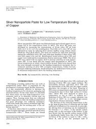
Fig. 4 — Top view of GMA welds produced us<strong>in</strong>g a reactive shield<strong>in</strong>g gas, 40 mm/s weld<strong>in</strong>g speed. A<br />
— 6 kW; B — 8 kW; and C — 11 kW weld<strong>in</strong>g power.<br />
Fig. 5 — A schematic diagram show<strong>in</strong>g various components<br />
of the LaserStrobe video imag<strong>in</strong>g system.<br />
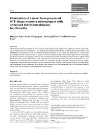
Fig. 7 — A close-up top view of a bead-on-plate GMA weld show<strong>in</strong>g the<br />
aperiodic discont<strong>in</strong>uous weld bead defect.<br />
Fig. 6 — Top view of GMA welds produced us<strong>in</strong>g 6.3 kW weld<strong>in</strong>g power,<br />
argon shield<strong>in</strong>g gas, and at various weld<strong>in</strong>g speeds.<br />
frequency has been shown to <strong>in</strong>crease with<br />
<strong>in</strong>creas<strong>in</strong>g weld<strong>in</strong>g speed or decreas<strong>in</strong>g<br />
weld<strong>in</strong>g power (Ref. 24).<br />
Dur<strong>in</strong>g their study of the hump<strong>in</strong>g phenomena<br />
<strong>in</strong> high-speed GMA weld<strong>in</strong>g of<br />
pla<strong>in</strong> carbon steel, Nguyen et al. (Refs. 5,<br />
17, 24) observed a change <strong>in</strong> the humped<br />
weld bead morphology when welds were<br />
performed us<strong>in</strong>g reactive shield<strong>in</strong>g gases<br />
and weld<strong>in</strong>g powers greater than 9 kW.<br />
Figure 4 shows three GMA welds that<br />
were produced at 40 mm/s weld<strong>in</strong>g speed<br />
us<strong>in</strong>g a reactive shield<strong>in</strong>g gas and <strong>in</strong>creas<strong>in</strong>g<br />
weld<strong>in</strong>g powers of 6, 8, and 11 kW.<br />
<strong>The</strong>se welds have been<br />
cleaned by sandblast<strong>in</strong>g<br />
to clearly reveal<br />
the different geometric<br />
features of the<br />
bead. As shown <strong>in</strong> Fig.<br />
4A, a good GMA weld<br />
was produced when<br />
us<strong>in</strong>g 6 kW weld<strong>in</strong>g<br />
power and hump<strong>in</strong>g<br />
was observed when the weld<strong>in</strong>g power was<br />
<strong>in</strong>creased to 8 kW — Fig. 4B. However, as<br />
shown <strong>in</strong> Fig. 4C, when the weld<strong>in</strong>g power<br />
was further <strong>in</strong>creased to 11 kW, the GMA<br />
weld produced showed a dist<strong>in</strong>ctly different<br />
type of geometric weld defect that is<br />
clearly not hump<strong>in</strong>g. <strong>The</strong> regular, periodic<br />
behavior of hump<strong>in</strong>g was no longer evident<br />
and the curved wall jet <strong>in</strong> the valleys<br />
of the high-speed weld bead defect was no<br />
longer present. This new high-speed defect<br />
is referred to here as the discont<strong>in</strong>uous<br />
weld bead defect, because the defective<br />
weld bead as shown <strong>in</strong> Fig. 4C is broken<br />
up <strong>in</strong>to several good bead segments by<br />
aperiodic or irregularly spaced valleys or<br />
depressions where melt<strong>in</strong>g of the base<br />
metal occurred but no filler metal was deposited.<br />
In addition, while the normally<br />
observed decrease <strong>in</strong> critical weld<strong>in</strong>g<br />
speed with <strong>in</strong>creas<strong>in</strong>g weld<strong>in</strong>g power was<br />
evident at the lower powers when hump<strong>in</strong>g<br />
occurred, the critical weld<strong>in</strong>g speed<br />
was not affected by the weld<strong>in</strong>g power<br />
when this new weld bead defect was observed.<br />
This particular aperiodic highspeed<br />
GMA weld bead defect has not<br />
been previously identified or reported <strong>in</strong><br />
the literature (Refs. 1–5, 17, 24). <strong>The</strong> objectives<br />
of the present study (Ref. 24),<br />
therefore, were to observe, identify, experimentally<br />
validate, and understand the<br />
physical mechanisms responsible for this<br />
new discont<strong>in</strong>uous weld bead defect that<br />
occurred dur<strong>in</strong>g high-speed GMA weld<strong>in</strong>g<br />
of pla<strong>in</strong> carbon steel.<br />
362-s<br />
NOVEMBER 2007, VOL. 86
Experimental Apparatus<br />
and Procedures<br />
In the present study, bead-on-plate<br />
GMA welds were made us<strong>in</strong>g a Fanuc<br />
ARC Mate 120i 6-axis weld<strong>in</strong>g robot and<br />
a L<strong>in</strong>coln PowerWave 455 power supply<br />
operat<strong>in</strong>g <strong>in</strong> constant voltage mode with<br />
an <strong>in</strong>tegrated Power Feed 10 wire feeder<br />
over a wide range of preset weld<strong>in</strong>g speeds<br />
and weld<strong>in</strong>g powers. A PC-microcomputer<br />
was used with Labview software<br />
and National Instruments-based dataacquisition<br />
system to record the weld<strong>in</strong>g<br />
voltage and current. Voltage between the<br />
contact tip and the workpiece was measured<br />
at the rate of 1000 samples/s us<strong>in</strong>g a<br />
LEM LV100 voltage transducer and the<br />
weld<strong>in</strong>g current was measured us<strong>in</strong>g a<br />
LEM LT505-S current transducer. <strong>The</strong><br />
measured voltages, V (V), and currents,<br />
I (A), were then postprocessed to calculate<br />
the time averaged weld<strong>in</strong>g power, P<br />
(W), us<strong>in</strong>g P = V × I.<br />
A LaserStrobe video system (Ref.<br />
25) was used to observe and to record images<br />
of the hump<strong>in</strong>g phenomenon dur<strong>in</strong>g<br />
bead-on-plate GMA weld<strong>in</strong>g of pla<strong>in</strong> carbon<br />
steel plate. As shown schematically <strong>in</strong><br />
Fig. 5, the LaserStrobe video imag<strong>in</strong>g<br />
system consisted of a video camera, a<br />
video recorder (VCR), a pulsed nitrogen<br />
(N 2 ) laser strobe with fiber-optic beam delivery,<br />
a data-acquisition system, and a<br />
personal computer that acted as a system<br />
controller. <strong>The</strong> pulsed N 2 laser strobe was<br />
used to overwhelm the <strong>in</strong>tense radiation<br />
of the GMA weld<strong>in</strong>g arc s<strong>in</strong>ce the laser<br />
light was much brighter than the light<br />
com<strong>in</strong>g from the weld<strong>in</strong>g arc at the N 2<br />
laser wavelength (Ref. 25). <strong>The</strong> laserillum<strong>in</strong>ated<br />
scene was viewed by a video<br />
camera equipped with a CCD video sensor,<br />
a narrow band-pass filter centered on<br />
the 337.1-nm wavelength of the N 2 laser,<br />
and an image <strong>in</strong>tensifier that was also used<br />
as a high-speed electronic shutter. <strong>The</strong><br />
image <strong>in</strong>tensifier limits the resolution of<br />
the LaserStrobe image to about 420 l<strong>in</strong>e<br />
pairs <strong>in</strong> the horizontal direction (Ref. 25).<br />
<strong>The</strong> computer synchronized the camera’s<br />
electronic shutter with the laser pulses.<br />
<strong>The</strong> comb<strong>in</strong>ation of temporal filter<strong>in</strong>g<br />
provided by the electronic shutter, N 2<br />
laser pulse synchronization, and spectral<br />
filter<strong>in</strong>g from the narrow band-pass filter<br />
allowed unobstructed view<strong>in</strong>g of the<br />
events tak<strong>in</strong>g place dur<strong>in</strong>g the formation<br />
of humped GMA welds without the <strong>in</strong>tense<br />
light from the weld<strong>in</strong>g arc. Dur<strong>in</strong>g<br />
film<strong>in</strong>g, the video camera was mounted on<br />
a fixture that moved along with the GMA<br />
weld<strong>in</strong>g torch.<br />
All bead-on-plate GMA welds were<br />
made <strong>in</strong> the flat position on degreased<br />
6.5-mm- (¼-<strong>in</strong>.-) thick cold-rolled SAE-<br />
AISI 1018 pla<strong>in</strong> carbon steel plates us<strong>in</strong>g<br />
WELDING RESEARCH<br />
Fig. 8 — A photomicrograph show<strong>in</strong>g the transverse<br />
section of a good bead segment of a GMA<br />
weld with discont<strong>in</strong>uous defect. <strong>The</strong> weld was produced<br />
us<strong>in</strong>g TIME shield<strong>in</strong>g gas, 10 kW weld<strong>in</strong>g<br />
power, and 30 mm/s weld<strong>in</strong>g speed.<br />
0.9-mm- (0.035-<strong>in</strong>.-) diameter ER70S-3<br />
and ER70S-6 electrode wires and a 22-mm<br />
contact tip-to-workpiece distance. <strong>The</strong> majority<br />
of GMA weld<strong>in</strong>g experiments were<br />
performed us<strong>in</strong>g ER70S-6 electrode wire.<br />
However, ER70S-3 electrode was also employed<br />
to determ<strong>in</strong>e the effects of the differences<br />
<strong>in</strong> chemical composition of the<br />
filler metal on the formation of high-speed<br />
weld defects. <strong>The</strong> nom<strong>in</strong>al chemical compositions<br />
of these GMAW electrode wires<br />
are as listed <strong>in</strong> Table 1 (Ref. 3). Both of<br />
these electrodes have relatively high levels<br />
of the deoxidiz<strong>in</strong>g elements, Mg and Si.<br />
<strong>The</strong> ER70S-6 electrode wire has the highest<br />
concentrations of Mg and Si and is often<br />
recommended for applications that use<br />
high weld<strong>in</strong>g current or GMAW over steel<br />
plates that are covered with light rust,<br />
whereas the ER70S-3 electrode is recommended<br />
when weld<strong>in</strong>g clean steel with<br />
argon-based shield<strong>in</strong>g gases (Ref. 3). In all<br />
cases, the work<strong>in</strong>g angle of the GMAW gun<br />
was 90 deg and the travel angle was 0 deg.<br />
Three different weld<strong>in</strong>g-grade shield<strong>in</strong>g<br />
gases were used: argon, Mig Mix<br />
Gold (MMG 1 ) and TIME 2 . <strong>The</strong><br />
composition of each shield<strong>in</strong>g gas is listed<br />
<strong>in</strong> Table 2. In this study, argon was an <strong>in</strong>ert<br />
shield<strong>in</strong>g gas while MMG and TIME <br />
were reactive shield<strong>in</strong>g gases due to their<br />
oxygen (O 2 ) and carbon dioxide (CO 2 )<br />
contents.<br />
To determ<strong>in</strong>e the usable weld<strong>in</strong>g<br />
speeds at each power level, the weld bead<br />
profiles were exam<strong>in</strong>ed and the maximum<br />
weld<strong>in</strong>g speed that produced a nonhumped<br />
or acceptable weld bead was<br />
recorded. For example, Fig. 6 conta<strong>in</strong>s<br />
photographs show<strong>in</strong>g the top view of<br />
GMA welds produced us<strong>in</strong>g 6.3 kW weld<strong>in</strong>g<br />
power, argon shield<strong>in</strong>g gas, and 10, 11,<br />
and 12 mm/s weld<strong>in</strong>g speeds, respectively.<br />
In Fig. 6, the welds produced at 10 mm/s<br />
weld<strong>in</strong>g speeds or slower were classified as<br />
good welds, s<strong>in</strong>ce the weld beads show no<br />
significant variation <strong>in</strong> weld dimensions or<br />
shape along the length of the weld. However,<br />
at 11 mm/s weld<strong>in</strong>g speed, the weld<br />
Table 1 — <strong>The</strong> Nom<strong>in</strong>al Chemical<br />
Compositions of ER70S-3 and ER70S-6<br />
Electrode Wires <strong>in</strong> wt-% (Ref. 3)<br />
Carbon Manganese Silicon<br />
ER70S-3 0.06–0.15 0.90–1.40 0.45–0.70<br />
ER70S-6 0.07–0.15 1.40–1.85 0.80–1.15<br />
Note: Phosphorus 0.025 max. and Sulfur 0.035 max.<br />
Table 2 — Compositions of the GMAW<br />
Shield<strong>in</strong>g <strong>Gas</strong>es Used<br />
Shield<strong>in</strong>g <strong>Gas</strong><br />
Composition<br />
Argon 100% Ar (ultrahigh purity grade)<br />
MMG 92% Ar, 8% CO 2<br />
TIME 65% Ar, 8% CO 2 , 26.5% He, 0.5% O 2<br />
bead beg<strong>in</strong>s to exhibit <strong>in</strong>termittent<br />
swell<strong>in</strong>gs that are separated by valleys.<br />
<strong>The</strong> occurrence of the humps and valleys<br />
becomes consistently periodic at 12 mm/s<br />
weld<strong>in</strong>g speed. Thus, the difference between<br />
good weld beads and a humped<br />
weld can be clearly identified by the significant<br />
variations <strong>in</strong> weld bead dimensions<br />
and shape that occur along the<br />
length of the humped weld bead and the<br />
occurrence of regularly spaced humps and<br />
valleys. Based on the weld beads shown <strong>in</strong><br />
Fig. 6, the limit<strong>in</strong>g weld<strong>in</strong>g speed for production<br />
of good argon-shielded GMA<br />
welds us<strong>in</strong>g 6.3-kW weld<strong>in</strong>g power was<br />
10 mm/s. This procedure was also used to<br />
determ<strong>in</strong>e the critical or maximum weld<strong>in</strong>g<br />
speed that could be used before the<br />
newly identified discont<strong>in</strong>uous weld bead<br />
defect became evident.<br />
Results and Discussion<br />
Geometric Features of the <strong>Discont<strong>in</strong>uous</strong><br />
<strong>Weld</strong> <strong>Bead</strong> <strong>Defect</strong><br />
As the weld<strong>in</strong>g power was <strong>in</strong>creased<br />
from 5 to 9 kW, the onset of high-speed<br />
weld defects <strong>in</strong> GMA welds produced<br />
us<strong>in</strong>g the reactive shield<strong>in</strong>g gases occurred<br />
at lower weld<strong>in</strong>g speeds. <strong>The</strong> high-speed<br />
weld defect observed was primarily hump<strong>in</strong>g.<br />
<strong>The</strong> results of these experiments and<br />
an explanation of the periodic hump<strong>in</strong>g<br />
phenomenon <strong>in</strong> high-speed GMA weld<strong>in</strong>g<br />
are reported <strong>in</strong> detail <strong>in</strong> a previous article<br />
by Nguyen et al. (Ref. 17). However, at<br />
weld<strong>in</strong>g powers greater than 9 kW, the<br />
filler metal transfer mode <strong>in</strong> the GMAW<br />
process was observed to change from<br />
1. MMG, Praxair Distribution, Inc., Kitchener,<br />
Ont., Canada.<br />
2. TIME, BOC <strong>Gas</strong>es Canada Ltd., Waterloo,<br />
Ont., Canada.<br />
WELDING JOURNAL<br />
363 -s
WELDING RESEARCH<br />
Fig. 9 — Top and longitud<strong>in</strong>al section views at the depression of a<br />
GMA weld with a discont<strong>in</strong>uous weld bead defect. <strong>The</strong> weld was produced<br />
right to left us<strong>in</strong>g 10 kW weld<strong>in</strong>g power, TIME shield<strong>in</strong>g gas,<br />
and 30 mm/s weld<strong>in</strong>g speed.<br />
spray to rotational transfer and there was<br />
a dist<strong>in</strong>ct change <strong>in</strong> the weld bead morphology<br />
as shown <strong>in</strong> Fig. 4C.<br />
Figure 7 shows a close-up top view of<br />
the aperiodic discont<strong>in</strong>uous weld bead defect.<br />
This particular weld was produced<br />
us<strong>in</strong>g 10 kW weld<strong>in</strong>g power, 30 mm/s<br />
weld<strong>in</strong>g speed, and TIME shield<strong>in</strong>g gas.<br />
Aga<strong>in</strong>, the top surface of the weld has<br />
been cleaned by sandblast<strong>in</strong>g to reveal all<br />
features of the weld. <strong>The</strong> weld bead is not<br />
cont<strong>in</strong>uous but is broken up <strong>in</strong>to segments<br />
of good weld bead by irregularly spaced<br />
depressions. As may be seen <strong>in</strong> Fig. 7, the<br />
adjacent good weld bead segments are<br />
connected by small metal channels on the<br />
outer edge of the depression. In addition,<br />
the discont<strong>in</strong>uous weld bead exhibits a significant<br />
amount of weld spatter immediately<br />
adjacent to the weld bead.<br />
A transverse section across a good<br />
bead segment of a discont<strong>in</strong>uous weld<br />
bead defect is shown <strong>in</strong> Fig. 8. This weld<br />
segment has a bead profile that shows<br />
good penetration, wide width, and excellent<br />
wett<strong>in</strong>g with the orig<strong>in</strong>al surface of<br />
the workpiece. At the deepest po<strong>in</strong>t, the<br />
depth of penetration is approximately<br />
1 mm. <strong>The</strong>re is no evidence of the characteristic<br />
f<strong>in</strong>ger penetration or nail-head<br />
weld profile that was typical of the welds<br />
produced us<strong>in</strong>g spray transfer at weld<strong>in</strong>g<br />
powers less than about 9 kW (Ref. 17).<br />
Figure 9 shows the top and the longitud<strong>in</strong>al<br />
section views of a GMA weld with<br />
the discont<strong>in</strong>uous weld bead defect from<br />
the end of one good weld segment across<br />
the depression to the beg<strong>in</strong>n<strong>in</strong>g of another<br />
good weld segment. <strong>The</strong> weld<strong>in</strong>g direction<br />
was from the right to left. <strong>The</strong> depression<br />
shown <strong>in</strong> Fig. 9 can be described as a cavity<br />
or a sunken valley between two good<br />
weld segments follow<strong>in</strong>g closely the shape<br />
of the fusion boundary. <strong>The</strong> fusion boundary<br />
of the depression has the same depth<br />
of penetration as the good weld bead segments.<br />
However, unlike the good segments<br />
of the weld bead, the depression has<br />
a shallower heat-affected zone (HAZ),<br />
which is del<strong>in</strong>eated by<br />
the dark band immediately<br />
located below the<br />
fusion boundary —<br />
Fig. 9. In this photomicrograph,<br />
the HAZ of<br />
the weld was revealed<br />
by etch<strong>in</strong>g the polished<br />
longitud<strong>in</strong>al section with a 5% Nital solution<br />
(Ref. 26). <strong>The</strong> shallower HAZ is an<br />
<strong>in</strong>dication that the total amount of heat<br />
<strong>in</strong>put was less at the depression compared<br />
to that along the good segments of the defective<br />
weld. This would suggest that the<br />
lack of the weld metal at the depression reduced<br />
the amount of sensible heat <strong>in</strong>put<br />
<strong>in</strong>to the base metal, thereby decreas<strong>in</strong>g<br />
the size of the HAZ.<br />
<strong>The</strong> good weld bead segment on the<br />
right side of Fig. 9 has a gradual forwardslop<strong>in</strong>g<br />
profile <strong>in</strong> the direction of weld<strong>in</strong>g.<br />
As <strong>in</strong>dicated, there is a slag particle on the<br />
top surface of the weld bead prior to the<br />
depression. Based on energy dispersive X-<br />
ray (EDX) analysis, this was a (Mn,Si) x O y<br />
glassy slag with about 7 at.-% Mn, 17<br />
at.-% Si, and 74 at.-% O with trace<br />
amounts of Fe and Al. <strong>The</strong>se features<br />
were typically seen at the end of GMA<br />
welds produced us<strong>in</strong>g the reactive shield<strong>in</strong>g<br />
gases. Meanwhile, beyond the depression,<br />
the start of the next weld bead segment<br />
did not have good wett<strong>in</strong>g with the<br />
bottom surface of the weld pool, s<strong>in</strong>ce its<br />
contact angle is very close to 90 deg (π/2<br />
radians). <strong>The</strong>se geometric features suggest<br />
that a momentary stoppage <strong>in</strong> the<br />
transfer of filler metal had occurred dur<strong>in</strong>g<br />
weld<strong>in</strong>g, s<strong>in</strong>ce these two adjacent weld<br />
bead segments appear to be the end of one<br />
and the beg<strong>in</strong>n<strong>in</strong>g of another GMA weld<br />
bead.<br />
To further exam<strong>in</strong>e the features of the<br />
depression, Fig. 10 shows a transverse section<br />
of a discont<strong>in</strong>uous GMA weld made<br />
us<strong>in</strong>g 10 kW weld<strong>in</strong>g power, TIME<br />
shield<strong>in</strong>g gas, and 30 mm/s weld<strong>in</strong>g speed.<br />
<strong>The</strong> transverse section was etched with<br />
5% Nital solution. In this photograph, the<br />
Fig. 10 — <strong>The</strong> transverse section and the top view at the depression of a<br />
GMA weld with discont<strong>in</strong>uous weld bead defect. <strong>The</strong> weld was made us<strong>in</strong>g<br />
10 kW weld<strong>in</strong>g power, TIME shield<strong>in</strong>g gas, and 30 mm/s weld<strong>in</strong>g speed.<br />
specimen was tilted forward to reveal the<br />
transverse section as well as the top view<br />
of the depression and the view is toward<br />
the tail of the weld. As <strong>in</strong>dicated <strong>in</strong> Fig. 10,<br />
there is a patch of (Mn,Si) x O y slag on the<br />
top surface of the previous good weld segment.<br />
Also, <strong>in</strong>side the cavity of the depression,<br />
there appears to be a very th<strong>in</strong><br />
layer of solidified weld metal. This is consistent<br />
with observations made by Yamamoto<br />
and Shimada (Ref. 10) and later<br />
by Mendez et al. (Refs. 19–21) of gouged<br />
weld pools dur<strong>in</strong>g high-speed autogenous<br />
GTA weld<strong>in</strong>g of sta<strong>in</strong>less steel.<br />
From the transverse section of the weld<br />
shown <strong>in</strong> Fig. 10, the HAZ is uniform <strong>in</strong><br />
thickness at the depression. In addition,<br />
there are two solidified channels or wall<br />
jets on both sides of the depression near<br />
the upper rim. <strong>The</strong>se weld metal wall jets<br />
connect the adjacent good segments of the<br />
discont<strong>in</strong>uous weld bead defect. <strong>The</strong>se solidified<br />
weld metal channels or wall jets<br />
are similar to those observed by Mendez<br />
et al. (Refs. 19–21) <strong>in</strong> their GTA welds.<br />
S<strong>in</strong>ce the molten weld metal flows around<br />
the rim of the depression and there is a<br />
th<strong>in</strong> layer of molten weld metal with<strong>in</strong> the<br />
depression, high arc pressure must have<br />
been present <strong>in</strong>side the depression dur<strong>in</strong>g<br />
weld<strong>in</strong>g. This geometric feature is very<br />
similar to that produced dur<strong>in</strong>g the highpower<br />
autogenous GTAW process, especially<br />
at high weld<strong>in</strong>g speeds. <strong>The</strong>se observations<br />
suggest that dur<strong>in</strong>g the time<br />
when the depression is created <strong>in</strong> the discont<strong>in</strong>uous<br />
weld bead, the GMA weld<strong>in</strong>g<br />
process behaves like an autogenous weld<strong>in</strong>g<br />
process with little or no filler metal<br />
transferred from the electrode to the<br />
workpiece.<br />
364-s<br />
NOVEMBER 2007, VOL. 86
WELDING RESEARCH<br />
A<br />
B<br />
C<br />
Fig. 11 — Regions of good and defective weld beads on weld<strong>in</strong>g<br />
speed vs. weld<strong>in</strong>g power plot for — A — Argon, B — MMG,<br />
and C — TIME shield<strong>in</strong>g gases.<br />
Fig. 12 — <strong>The</strong> filler metal transfer modes as a function of the weld<strong>in</strong>g powers and shield<strong>in</strong>g<br />
gases. In these images, the diameter of the filler metal electrode wire is 0.9 mm.<br />
Effects of <strong>Weld</strong><strong>in</strong>g Power and<br />
<strong>Weld</strong><strong>in</strong>g <strong>Speed</strong><br />
In a previous study of the hump<strong>in</strong>g<br />
phenomenon <strong>in</strong> GMA weld<strong>in</strong>g, the total<br />
weld<strong>in</strong>g power used was varied from<br />
5 to 9 kW (Ref. 17). In the present study<br />
of the discont<strong>in</strong>uous weld bead defect,<br />
however, the total weld<strong>in</strong>g power was <strong>in</strong>creased<br />
further to 10, 11, and 12 kW. For<br />
each different comb<strong>in</strong>ation of weld<strong>in</strong>g<br />
power and shield<strong>in</strong>g gas, the previously<br />
described experimental procedure for determ<strong>in</strong><strong>in</strong>g<br />
the limit<strong>in</strong>g weld<strong>in</strong>g speed was<br />
performed. <strong>The</strong> new limit<strong>in</strong>g weld<strong>in</strong>g<br />
speeds generated from these experiments<br />
were then comb<strong>in</strong>ed with previous data<br />
and plotted.<br />
WELDING JOURNAL<br />
365-s
Fig. 13 — <strong>The</strong> flight path of molten filler metal<br />
droplets <strong>in</strong> rotational transfer mode at 11 kW us<strong>in</strong>g<br />
argon shield<strong>in</strong>g gas.<br />
<strong>The</strong> three graphs displayed <strong>in</strong> Fig. 11<br />
are process maps show<strong>in</strong>g regions or<br />
ranges of weld<strong>in</strong>g power and weld<strong>in</strong>g<br />
speed that resulted <strong>in</strong> good and defective<br />
weld beads when us<strong>in</strong>g the three different<br />
shield<strong>in</strong>g gases: argon, MMG, and<br />
TIME. On these plots, the connect<strong>in</strong>g<br />
l<strong>in</strong>e segments represent the maximum or<br />
limit<strong>in</strong>g weld<strong>in</strong>g speeds that could be used<br />
to produce a GMA weld without a defective<br />
weld bead profile. <strong>The</strong> area located directly<br />
underneath the limit<strong>in</strong>g weld<strong>in</strong>g<br />
speeds represents various comb<strong>in</strong>ations of<br />
weld<strong>in</strong>g speed and weld<strong>in</strong>g power that<br />
produced good or acceptable GMA weld<br />
beads. For convenience, these areas are labeled<br />
as good weld regions on the plots.<br />
WELDING RESEARCH<br />
Fig. 14 — An image of rotational transfer mode<br />
produced us<strong>in</strong>g argon shield<strong>in</strong>g gas and 12 kW<br />
weld<strong>in</strong>g power show<strong>in</strong>g the detachment of a long<br />
str<strong>in</strong>g fragment from the molten filler metal str<strong>in</strong>g.<br />
Fig. 15 — <strong>The</strong> relative frequency of the breakup of the molten filler metal str<strong>in</strong>g at three different weld<strong>in</strong>g<br />
power levels and three different shield<strong>in</strong>g gases.<br />
As the speed is <strong>in</strong>creased beyond the limit<strong>in</strong>g<br />
weld<strong>in</strong>g speeds, a geometrically defective<br />
or unacceptable weld bead was observed.<br />
Note that the limit<strong>in</strong>g weld<strong>in</strong>g<br />
speeds and the types of high-speed weld<br />
defect for GMA welds produced us<strong>in</strong>g<br />
MMG shield<strong>in</strong>g gas and ER70S-3 electrode<br />
wire are also plotted <strong>in</strong> Fig. 11B. As<br />
may be seen <strong>in</strong> Fig. 11, there were two<br />
types of geometric weld bead defects observed<br />
at higher weld<strong>in</strong>g speeds: humped<br />
and discont<strong>in</strong>uous weld beads as shown <strong>in</strong><br />
Fig. 6B and C, respectively. <strong>The</strong> type of<br />
high-speed weld defect observed was a<br />
function of the shield<strong>in</strong>g gas and the weld<strong>in</strong>g<br />
power used to make the weld. In addition,<br />
there is no significant difference between<br />
the results when ER70S-3 or<br />
ER70S-6 electrode wires were used with<br />
MMG shield<strong>in</strong>g gas.<br />
When us<strong>in</strong>g both the MMG and<br />
TIME shield<strong>in</strong>g gases and less than<br />
9 kW weld<strong>in</strong>g power, the usable weld<strong>in</strong>g<br />
speed was limited by the occurrence of<br />
hump<strong>in</strong>g. In this range of weld<strong>in</strong>g power,<br />
as the weld<strong>in</strong>g power was <strong>in</strong>creased,<br />
hump<strong>in</strong>g occurred at lower weld<strong>in</strong>g<br />
speeds — Fig. 11B, C. When us<strong>in</strong>g lower<br />
weld<strong>in</strong>g powers and TIME shield<strong>in</strong>g<br />
gas, defect-free welds were produced at<br />
slightly higher weld<strong>in</strong>g speeds than those<br />
made us<strong>in</strong>g MMG shield<strong>in</strong>g gas. However,<br />
this advantage dim<strong>in</strong>ished with <strong>in</strong>creas<strong>in</strong>g<br />
weld<strong>in</strong>g power. On the other<br />
hand, when us<strong>in</strong>g argon shield<strong>in</strong>g gas,<br />
there was a small <strong>in</strong>crease <strong>in</strong> limit<strong>in</strong>g weld<strong>in</strong>g<br />
speeds with higher weld<strong>in</strong>g powers.<br />
This limit<strong>in</strong>g weld<strong>in</strong>g speed <strong>in</strong>crease when<br />
us<strong>in</strong>g Ar shield<strong>in</strong>g gas was thought to be<br />
due to the effects of the transition from<br />
stream<strong>in</strong>g to sw<strong>in</strong>g<strong>in</strong>g spray transfer<br />
modes of the filler metal on the hump<strong>in</strong>g<br />
phenomenon (Ref. 17).<br />
When the weld<strong>in</strong>g power was <strong>in</strong>creased<br />
beyond 9 kW, the limit<strong>in</strong>g weld<strong>in</strong>g speed<br />
for welds produced us<strong>in</strong>g the argon shield<strong>in</strong>g<br />
gases leveled out at approximately 15<br />
mm/s and became <strong>in</strong>dependent of the<br />
weld<strong>in</strong>g power — Fig. 11A. <strong>The</strong> same<br />
trend was also observed for GMA welds<br />
produced us<strong>in</strong>g the reactive shield<strong>in</strong>g<br />
gases, MMG and TIME; however, the<br />
limit<strong>in</strong>g weld<strong>in</strong>g speeds were greater at<br />
approximately 22 mm/s — Fig. 11B, C. As<br />
<strong>in</strong>dicated <strong>in</strong> Fig. 11A–C, as the weld<strong>in</strong>g<br />
power was <strong>in</strong>creased beyond 9 kW when<br />
us<strong>in</strong>g argon shield<strong>in</strong>g gas, the observed<br />
high-speed weld defect was still hump<strong>in</strong>g,<br />
whereas when us<strong>in</strong>g the reactive shield<strong>in</strong>g<br />
gases, the usable weld<strong>in</strong>g speed was limited<br />
by the onset of the discont<strong>in</strong>uous weld<br />
bead defect. In addition, there was a dist<strong>in</strong>ct<br />
po<strong>in</strong>t of <strong>in</strong>flection between the limit<strong>in</strong>g<br />
weld<strong>in</strong>g speed l<strong>in</strong>es for hump<strong>in</strong>g versus<br />
the discont<strong>in</strong>uous weld bead defect.<br />
This po<strong>in</strong>t of <strong>in</strong>flection and change <strong>in</strong> behavior<br />
at weld<strong>in</strong>g powers greater than 9<br />
kW is <strong>in</strong>dicative that a transition has taken<br />
place <strong>in</strong> the physical phenomena tak<strong>in</strong>g<br />
place dur<strong>in</strong>g GMA weld<strong>in</strong>g such as a<br />
change <strong>in</strong> the filler metal transfer mechanism.<br />
<strong>The</strong> filler metal transfer mode <strong>in</strong> the<br />
GMA weld<strong>in</strong>g process is known to change<br />
from globular to spray and f<strong>in</strong>ally to rotational<br />
transfer with <strong>in</strong>creas<strong>in</strong>g weld<strong>in</strong>g<br />
power (Ref. 4). In the follow<strong>in</strong>g, therefore,<br />
the relationship between the filler<br />
metal transfer modes and the weld<strong>in</strong>g<br />
power levels is explored.<br />
<strong>The</strong> Filler <strong>Metal</strong> Transfer Modes<br />
Individual LaserStrobe video frames<br />
show<strong>in</strong>g the typical filler metal transfer<br />
366-s<br />
NOVEMBER 2007, VOL. 86
modes observed when us<strong>in</strong>g the different<br />
shield<strong>in</strong>g gases and weld<strong>in</strong>g powers are<br />
shown <strong>in</strong> Fig. 12. <strong>The</strong> welds produced<br />
us<strong>in</strong>g argon shield<strong>in</strong>g gas had the longest<br />
arc length of about 9 mm whereas the<br />
welds produced us<strong>in</strong>g MMG and<br />
TIME shield<strong>in</strong>g gases were typically<br />
about 50% shorter. Between weld<strong>in</strong>g powers<br />
of 5 and 7.5 kW, the spray transfer<br />
mode is evident for all shield<strong>in</strong>g gases. At<br />
these weld<strong>in</strong>g power levels, the molten<br />
filler metal droplets detached from the<br />
end of the electrode wire and were propelled<br />
straight down through the weld<strong>in</strong>g<br />
arc to the weld pool. <strong>The</strong> molten filler<br />
metal droplets for the argon shield<strong>in</strong>g gas<br />
was found to have a more constricted<br />
flight path result<strong>in</strong>g <strong>in</strong> a smaller imp<strong>in</strong>gement<br />
area on the top surface of the weld<br />
pool (Ref. 17). Meanwhile, the molten<br />
filler metal droplets for welds produced<br />
us<strong>in</strong>g reactive shield<strong>in</strong>g gases are spread<br />
out and this resulted <strong>in</strong> larger imp<strong>in</strong>gement<br />
areas and weld widths (Ref. 17).<br />
Between weld<strong>in</strong>g powers of 7.5 and<br />
9 kW, the filler metal transfer mode for all<br />
shield<strong>in</strong>g gases was predom<strong>in</strong>antly spray<br />
transfer. However, as shown <strong>in</strong> Fig. 12, the<br />
<strong>in</strong>dividual filler metal droplets were<br />
swung around <strong>in</strong> a helical path as they detached<br />
from the tip of the electrode wire<br />
and propelled across the weld<strong>in</strong>g arc to<br />
the weld pool. This is identified as sw<strong>in</strong>g<strong>in</strong>g<br />
spray transfer mode, which is considered<br />
to be a transitional stage between<br />
spray and rotational transfer modes (Ref.<br />
27). For the GMA welds produced us<strong>in</strong>g<br />
argon shield<strong>in</strong>g gas, the sw<strong>in</strong>g<strong>in</strong>g spray<br />
transfer mode can facilitate higher weld<strong>in</strong>g<br />
speeds s<strong>in</strong>ce it reduces the vertical velocity<br />
component of the molten filler<br />
metal droplets to lessen their ability to<br />
gouge the weld pool enlarges the imp<strong>in</strong>gement<br />
area on the top surface of the<br />
weld pool, and prevents the molten filler<br />
metal droplets from always hitt<strong>in</strong>g the<br />
lead<strong>in</strong>g edge of the gouged weld pool. This<br />
reduces the momentum of the molten<br />
weld metal toward the rear of the weld<br />
pool, thereby suppress<strong>in</strong>g the tendency for<br />
hump<strong>in</strong>g to occur until high weld<strong>in</strong>g<br />
speeds are used (Ref. 17).<br />
As shown <strong>in</strong> Fig. 12, above 9 kW weld<strong>in</strong>g<br />
power, the weld<strong>in</strong>g wire melts and<br />
forms a long liquid str<strong>in</strong>g that is still attached<br />
to the solid tip of the electrode.<br />
This molten filler metal str<strong>in</strong>g is <strong>in</strong>discrim<strong>in</strong>ately<br />
coiled and violently swung<br />
around <strong>in</strong>side the shroud of the weld<strong>in</strong>g<br />
arc. This is identified as the rotational<br />
transfer mode, which typically occurs at<br />
power levels higher than those obta<strong>in</strong>ed<br />
for spray transfer (Refs. 28, 29). <strong>The</strong> direction<br />
of rotation of the molten filler<br />
metal str<strong>in</strong>g is random even when identical<br />
weld<strong>in</strong>g parameters are used (Ref. 30).<br />
In general, the rotational transfer mode<br />
WELDING RESEARCH<br />
A<br />
Fig. 16 — <strong>The</strong> LaserStrobe video images show<strong>in</strong>g the effect of radial p<strong>in</strong>ch <strong>in</strong>stability on the molten filler<br />
metal str<strong>in</strong>g dur<strong>in</strong>g GMA weld<strong>in</strong>g of steel us<strong>in</strong>g argon shield<strong>in</strong>g gas and 11 kW weld<strong>in</strong>g power. Depend<strong>in</strong>g<br />
on the orientation, the molten filler metal str<strong>in</strong>g can be viewed as dark field <strong>in</strong> A or a bright field <strong>in</strong> B.<br />
A<br />
Fig. 17 — <strong>The</strong> breakup of the long filler metal str<strong>in</strong>g as a result of short circuit<strong>in</strong>g with the surface of the<br />
workpiece.<br />
produces the highest level of filler metal<br />
deposition rates when compared to other<br />
transfer modes (Refs. 1–4, 28, 29).<br />
From the results shown <strong>in</strong> Figs. 11 and<br />
12, the occurrence of the hump<strong>in</strong>g weld<br />
defect co<strong>in</strong>cides with the spray transfer<br />
mode. When us<strong>in</strong>g the reactive shield<strong>in</strong>g<br />
gases, however, the transition to rotational<br />
transfer mode co<strong>in</strong>cided with the<br />
appearance of the discont<strong>in</strong>uous weld<br />
bead defect. Thus, for reactive shield<strong>in</strong>g<br />
gases, the type of high-speed weld bead<br />
defect observed appears to be related to<br />
the filler metal transfer modes. To further<br />
understand the formation of the discont<strong>in</strong>uous<br />
weld bead defect, a more detailed<br />
exam<strong>in</strong>ation of the rotational transfer<br />
mode was undertaken.<br />
Rotational Transfer Mode dur<strong>in</strong>g<br />
GMA <strong>Weld</strong><strong>in</strong>g<br />
From the images <strong>in</strong> Fig. 12, rotational<br />
metal transfer mode occurred when the<br />
weld<strong>in</strong>g power was greater than 9 kW. <strong>The</strong><br />
filler metal droplets can be seen to detach<br />
from the tip of the molten str<strong>in</strong>g similar to<br />
that previously reported for rotational<br />
transfer mode <strong>in</strong> GMA weld<strong>in</strong>g (Refs.<br />
27–30). <strong>The</strong> flight path of the detached<br />
droplets was typically along the same l<strong>in</strong>e<br />
as the molten str<strong>in</strong>g. However, s<strong>in</strong>ce the<br />
str<strong>in</strong>g rotated <strong>in</strong> a random manner, the<br />
droplets were erratically deposited over<br />
the surface of the weld pool. For <strong>in</strong>stance,<br />
the image of an argon-shielded GMA<br />
weld at 11 kW weld<strong>in</strong>g power <strong>in</strong> Fig. 13<br />
shows that some of the molten filler metal<br />
droplets were detached <strong>in</strong> the weld<strong>in</strong>g direction<br />
and transferred to the front portion<br />
of the weld pool. In addition, the<br />
sw<strong>in</strong>g<strong>in</strong>g action of the molten filler metal<br />
str<strong>in</strong>g resulted <strong>in</strong> some of the droplets hav<strong>in</strong>g<br />
an upward flight path prior to fall<strong>in</strong>g<br />
back down to the weld pool. <strong>The</strong> sw<strong>in</strong>g<strong>in</strong>g<br />
action of the molten filler metal str<strong>in</strong>g and<br />
the erratic deposition of the molten filler<br />
metal droplets generated spatter on the<br />
surface of the workpiece adjacent to the<br />
weld bead — Fig. 7. Also visible <strong>in</strong> this and<br />
other images is a halo of glow<strong>in</strong>g gas<br />
around each metal droplet and a glow<strong>in</strong>g<br />
comet tail trail<strong>in</strong>g beh<strong>in</strong>d the droplets.<br />
This may be evidence of <strong>in</strong>teractions between<br />
vaporiz<strong>in</strong>g elements from the metal<br />
droplets such as Mn and the ionized high-<br />
B<br />
B<br />
WELDING JOURNAL<br />
367-s
WELDING RESEARCH<br />
A<br />
B<br />
Fig. 18 — <strong>The</strong> top surface of a GMA weld with discont<strong>in</strong>uous weld bead<br />
defect immediately after weld<strong>in</strong>g.<br />
C<br />
D<br />
E<br />
F<br />
Fig. 20 — LaserStrobe video image that shows the length of the depression<br />
formed.<br />
Fig. 19 — A sequence of six LaserStrobe video images show<strong>in</strong>g the formation of<br />
a discont<strong>in</strong>uous weld bead defect.<br />
velocity plasma stream <strong>in</strong> the arc.<br />
In addition to the droplets detach<strong>in</strong>g<br />
from the tip of the filler metal str<strong>in</strong>g, the<br />
molten filler metal str<strong>in</strong>g was also seen to<br />
be broken up <strong>in</strong>to longer fragments that<br />
fell directly <strong>in</strong>to the weld pool. While<br />
metal transfer by droplet detachment has<br />
been observed and reported <strong>in</strong> previous<br />
publications of rotational transfer mode <strong>in</strong><br />
GMAW (Refs. 27–30), this is the first time<br />
that metal transfer by fragmentation or<br />
complete detachment of the long molten<br />
metal str<strong>in</strong>g on the end of the electrode<br />
has been observed. An image of the fragmented<br />
molten filler metal str<strong>in</strong>g is shown<br />
<strong>in</strong> Fig. 14. Detachment of the long str<strong>in</strong>g<br />
fragment shortened the molten filler<br />
metal str<strong>in</strong>g considerably. In this case, the<br />
orig<strong>in</strong>al molten str<strong>in</strong>g was cut <strong>in</strong> half as a<br />
result of the breakup. At the new tip of the<br />
str<strong>in</strong>g, a new molten filler metal droplet<br />
was form<strong>in</strong>g and would be detached very<br />
shortly.<br />
Fragmentation of the molten filler<br />
metal str<strong>in</strong>g was not restricted to argonshielded<br />
welds. Similar LaserStrobe<br />
video images show<strong>in</strong>g the breakup of a<br />
long molten filler metal str<strong>in</strong>g were also<br />
found for welds produced us<strong>in</strong>g the reactive<br />
shield<strong>in</strong>g gases. For each shield<strong>in</strong>g gas<br />
and weld<strong>in</strong>g power comb<strong>in</strong>ation, 600<br />
LaserStrobe video images were exam<strong>in</strong>ed<br />
to determ<strong>in</strong>e the number of frames<br />
that clearly showed the fragment of the<br />
molten filler metal str<strong>in</strong>g. <strong>The</strong> results were<br />
then divided by 600 and converted to a<br />
percentage to represent the probability of<br />
hav<strong>in</strong>g the long molten filler metal str<strong>in</strong>g<br />
break<strong>in</strong>g up <strong>in</strong>to fragments. <strong>The</strong> probability<br />
of hav<strong>in</strong>g a fragmented str<strong>in</strong>g when<br />
us<strong>in</strong>g each shield<strong>in</strong>g gas at 10, 11, and 12<br />
kW weld<strong>in</strong>g power are plotted <strong>in</strong> Fig. 15.<br />
From these results, the molten filler metal<br />
str<strong>in</strong>g that exists dur<strong>in</strong>g rotational transfer<br />
mode occasionally broke up <strong>in</strong>to long<br />
fragments rather than droplets. <strong>The</strong> probability<br />
of break<strong>in</strong>g up <strong>in</strong>to str<strong>in</strong>g fragments<br />
was highest for argon followed by MMG<br />
and TIME shield<strong>in</strong>g gases, respectively.<br />
For GMA welds produced us<strong>in</strong>g TIME<br />
shield<strong>in</strong>g gas, the breakup of the molten<br />
filler metal str<strong>in</strong>g is constant at about 4%<br />
and relatively <strong>in</strong>dependent of the weld<strong>in</strong>g<br />
power. Meanwhile, for welds produced<br />
us<strong>in</strong>g MMG shield<strong>in</strong>g gas, there is a<br />
slight reduction <strong>in</strong> the frequency of breakup<br />
of the long molten filler metal str<strong>in</strong>g<br />
<strong>in</strong>to fragments at lower weld<strong>in</strong>g powers.<br />
Lastly, the weld<strong>in</strong>g power had the most <strong>in</strong>fluence<br />
when us<strong>in</strong>g argon shield<strong>in</strong>g gas;<br />
the higher the weld<strong>in</strong>g power, the more<br />
frequent was the breakup of the long<br />
molten filler metal str<strong>in</strong>g. In fact, on <strong>in</strong>creas<strong>in</strong>g<br />
the weld<strong>in</strong>g power from 10 to<br />
12 kW (20% <strong>in</strong>crease), the frequency of<br />
str<strong>in</strong>g fragmentation more than doubled;<br />
i.e., it <strong>in</strong>creased from 6 to 13%.<br />
If it is assumed that the molten filler<br />
metal str<strong>in</strong>g can be approximated as a<br />
fluid cyl<strong>in</strong>der, then the GMAW filler<br />
metal transfer modes can be attributed to<br />
<strong>in</strong>fluences of either the radial p<strong>in</strong>ch or<br />
k<strong>in</strong>k <strong>in</strong>stabilities (Ref. 27). <strong>The</strong> radial<br />
p<strong>in</strong>ch <strong>in</strong>stability of the fluid cyl<strong>in</strong>der is responsible<br />
for the formation and the detachment<br />
of molten filler metal droplets <strong>in</strong><br />
the globular and spray transfer modes dur<strong>in</strong>g<br />
GMA weld<strong>in</strong>g. Meanwhile, the sw<strong>in</strong>g<strong>in</strong>g<br />
action of the molten filler metal str<strong>in</strong>g<br />
observed <strong>in</strong> rotational filler metal transfer<br />
mode is caused by the effect of the k<strong>in</strong>k <strong>in</strong>stability<br />
on the fluid cyl<strong>in</strong>der. This particular<br />
<strong>in</strong>stability can be described geometrically<br />
as the collapse of a straight fluid<br />
cyl<strong>in</strong>der <strong>in</strong>to a spiral shape (Ref. 27). Dur<strong>in</strong>g<br />
rotational transfer mode, however, the<br />
radial p<strong>in</strong>ch <strong>in</strong>stability is also present and<br />
is responsible for the detachment of<br />
droplets from the tip of the molten str<strong>in</strong>g<br />
<strong>in</strong> rotational transfer mode as shown <strong>in</strong><br />
the LaserStrobe video image of Fig. 13.<br />
Thus, <strong>in</strong> rotational transfer mode, the effects<br />
of radial p<strong>in</strong>ch <strong>in</strong>stabilities on the<br />
fluid cyl<strong>in</strong>der are still present, but not<br />
dom<strong>in</strong>ant.<br />
Figure 16 shows two LaserStrobe<br />
video images of the molten filler metal<br />
str<strong>in</strong>g at different times dur<strong>in</strong>g GMA<br />
weld<strong>in</strong>g of steel us<strong>in</strong>g argon shield<strong>in</strong>g gas<br />
and 11 kW weld<strong>in</strong>g power. In Fig. 16A, the<br />
molten filler metal str<strong>in</strong>g is at an orientation<br />
such that the specular reflection of<br />
the N 2 laser light toward the CCD camera<br />
does not occur. As a result, the str<strong>in</strong>g <strong>in</strong><br />
this image appears mostly as a dark field.<br />
Meanwhile, <strong>in</strong> Fig. 16B, the molten filler<br />
metal str<strong>in</strong>g is a bright field s<strong>in</strong>ce its orientation<br />
allows the N 2 laser to be reflected<br />
back to the CCD camera of the Laser-<br />
Strobe video imag<strong>in</strong>g system.<br />
In Fig. 16A, the formation and detachment<br />
of molten filler metal droplets from<br />
the tip of the filler metal str<strong>in</strong>g are clearly<br />
observed. <strong>The</strong> spherical-shaped droplets<br />
368-s<br />
NOVEMBER 2007, VOL. 86
eflect the N 2 laser light back to the CCD<br />
camera. As a result, a bright spot on the<br />
surface of each droplet is clearly observed<br />
<strong>in</strong> the image. Although the str<strong>in</strong>g is seen<br />
as a dark field because the curved surface<br />
of the str<strong>in</strong>g does not allow the reflection<br />
of the N 2 laser back to the CCD camera,<br />
there are a few visible bright spots <strong>in</strong> Fig.<br />
16A. <strong>The</strong> bright spots are simply an <strong>in</strong>dication<br />
that the N 2 laser light is be<strong>in</strong>g reflected<br />
back to the CCD camera at these<br />
locations by specular reflections off a<br />
spherical shape similar to the molten filler<br />
metal droplets. In other words, these<br />
bright spots represent the swell<strong>in</strong>gs that<br />
occur along the length of the molten filler<br />
metal str<strong>in</strong>g. Similar to the formation of<br />
the droplets, the swell<strong>in</strong>gs are formed by<br />
radial p<strong>in</strong>ch<strong>in</strong>g of the molten filler metal<br />
str<strong>in</strong>g <strong>in</strong>to th<strong>in</strong>ner neck<strong>in</strong>g regions. <strong>The</strong><br />
th<strong>in</strong>n<strong>in</strong>g of these neck<strong>in</strong>g regions will ultimately<br />
result <strong>in</strong> breakup of the long<br />
molten filler metal str<strong>in</strong>g <strong>in</strong>to fragments as<br />
seen <strong>in</strong> Fig. 14.<br />
In Fig. 16B, a major portion of the<br />
molten filler metal str<strong>in</strong>g is seen as a bright<br />
field. At this <strong>in</strong>stant <strong>in</strong> time, the molten<br />
filler metal str<strong>in</strong>g had an orientation that<br />
allowed specular reflection of the N 2 laser<br />
light back to the CCD camera. However,<br />
there are several dark segments along the<br />
bright length of the molten filler metal<br />
str<strong>in</strong>g. <strong>The</strong> surface profile at the dark segments<br />
must be different than the rest of<br />
the molten filler metal str<strong>in</strong>g <strong>in</strong> order to<br />
cut off the specular reflection of the N 2<br />
laser light back to the CCD camera. If<br />
these dark segments have a swell<strong>in</strong>g or a<br />
spherical surface profile, then a bright<br />
spot similar to that observed for a droplet<br />
would be visible. However, this is not the<br />
case. As <strong>in</strong>dicated <strong>in</strong> Fig. 16B, these dark<br />
segments occur <strong>in</strong> between the bright segments<br />
of the molten filler metal str<strong>in</strong>g.<br />
From these observations, the dark portions<br />
must have p<strong>in</strong>ched or neck<strong>in</strong>g surface<br />
profiles, a direct result of a radial<br />
p<strong>in</strong>ch <strong>in</strong>stability.<br />
From the images <strong>in</strong> Fig. 16A, B, although<br />
it is not dom<strong>in</strong>ant, the radial p<strong>in</strong>ch<br />
<strong>in</strong>stability is present dur<strong>in</strong>g rotational<br />
transfer mode. In addition to produc<strong>in</strong>g<br />
and detach<strong>in</strong>g the droplets at the tip, the<br />
radial p<strong>in</strong>ch <strong>in</strong>stability also causes neck<strong>in</strong>g<br />
to form along the length of the molten<br />
filler metal str<strong>in</strong>g. <strong>The</strong> th<strong>in</strong>n<strong>in</strong>g of these<br />
neck<strong>in</strong>g regions will eventually break up<br />
the molten filler metal str<strong>in</strong>g <strong>in</strong>to fragments<br />
as seen <strong>in</strong> Fig. 14. <strong>The</strong> fragment of<br />
the molten filler metal str<strong>in</strong>g shortens the<br />
molten metal str<strong>in</strong>g considerably. In addition<br />
to neck<strong>in</strong>g, the long molten filler<br />
metal str<strong>in</strong>g can also be broken up <strong>in</strong>to<br />
fragments as the str<strong>in</strong>g momentarily<br />
touches the surface of the workpiece. This<br />
phenomenon is illustrated by the images<br />
<strong>in</strong> Fig. 17.<br />
WELDING RESEARCH<br />
Table 3 — <strong>The</strong> Voltage and the Measured <strong>Weld</strong><strong>in</strong>g Current at 10, 11, and 12 kW for Argon, MMG,<br />
and TIME Shield<strong>in</strong>g <strong>Gas</strong>es<br />
<strong>The</strong> LaserStrobe video images<br />
shown <strong>in</strong> Fig. 17A and B were taken approximately<br />
33 ms apart. In Fig. 17A, a<br />
long molten filler metal str<strong>in</strong>g was violently<br />
swung around with the end portion<br />
of the str<strong>in</strong>g about to touch the surface of<br />
the workpiece. In Fig. 17B, the molten<br />
filler metal str<strong>in</strong>g was broken up <strong>in</strong>to two<br />
segments. Dur<strong>in</strong>g the 33-ms time <strong>in</strong>terval<br />
between the first and the second images,<br />
the long molten filler metal str<strong>in</strong>g apparently<br />
touched the lead<strong>in</strong>g edge of the weld<br />
pool. This contact momentarily created a<br />
short circuit, which resulted <strong>in</strong> a surge of<br />
weld<strong>in</strong>g current. S<strong>in</strong>ce the molten filler<br />
metal str<strong>in</strong>g was <strong>in</strong> liquid form, a small<br />
current surge was needed to elim<strong>in</strong>ate the<br />
short circuit<strong>in</strong>g. In the process of elim<strong>in</strong>at<strong>in</strong>g<br />
the short circuit<strong>in</strong>g, the molten<br />
filler metal str<strong>in</strong>g was shattered <strong>in</strong>to fragments<br />
as shown <strong>in</strong> Fig. 17B.<br />
<strong>The</strong> Soot Layer<br />
Argon MMG TIME<br />
Voltage Avg. Current Voltage Avg. Current Voltage Avg. Current<br />
(V) (A) (V) (A) (V) (A)<br />
10 kW 32.5 306.5 34.5 288.0 35.5 278.4<br />
11 kW 33.0 326.1 35.0 315.0 36.0 306.7<br />
12 kW 36.0 333.7 37.3 326.9 38.5 311.5<br />
A layer of rust-colored soot was observed<br />
cover<strong>in</strong>g the bottom surface of<br />
many of the depressions of the discont<strong>in</strong>uous<br />
weld bead defect. <strong>The</strong> presence of a<br />
contam<strong>in</strong>ant layer can prevent molten<br />
weld metal from refill<strong>in</strong>g the gouged region<br />
of the weld pool by prevent<strong>in</strong>g contact<br />
and wett<strong>in</strong>g at the fusion boundary.<br />
As this could also contribute to the formation<br />
of the depressions that break up<br />
the weld bead <strong>in</strong>to segments, further exam<strong>in</strong>ation<br />
of the soot layer at the bottom<br />
of the depression and its effects on the formation<br />
of the discont<strong>in</strong>uous weld bead defect<br />
was undertaken.<br />
Figure 18 shows the as-welded top surface<br />
of a GMA weld with the discont<strong>in</strong>uous<br />
weld bead defect. <strong>The</strong> surface of the<br />
workpiece adjacent to the weld bead is<br />
covered with a thick layer of rust-colored<br />
soot, while the good weld bead segments<br />
are relatively clean. As noted <strong>in</strong> Fig. 18,<br />
the dark spots formed on the top surface<br />
at the end of each good weld bead segment<br />
were found to be a (Mn,Si) x O y glassy slag.<br />
In addition, there was a th<strong>in</strong> layer of soot<br />
completely cover<strong>in</strong>g the bottom surface of<br />
the depressions of the discont<strong>in</strong>uous weld<br />
bead. <strong>The</strong> chemical composition of the<br />
soot on the top surface of the adjacent<br />
workpiece and the soot cover<strong>in</strong>g the bottom<br />
surface of the depression were analyzed<br />
us<strong>in</strong>g a LEO FESEM 1530 field<br />
emission scann<strong>in</strong>g electron microscope<br />
equipped with an EDX analysis system.<br />
S<strong>in</strong>ce the soot just covered the top surface<br />
of the workpiece, the scann<strong>in</strong>g electron<br />
microscope was set at 15 keV to m<strong>in</strong>imize<br />
the <strong>in</strong>teraction volume between the electrons<br />
and the analyzed material (Ref. 31).<br />
<strong>The</strong> small <strong>in</strong>teraction volume ensured that<br />
the elements detected dur<strong>in</strong>g the chemical<br />
analysis belonged to the soot. <strong>The</strong> elemental<br />
constituents of the soot cover<strong>in</strong>g<br />
the top surface of the workpiece adjacent<br />
to the weld bead were identified as Fe,<br />
Mn, Si, Zn, and oxygen. S<strong>in</strong>ce the ER70S-<br />
6 electrode wire has a high content of deoxidizers<br />
such as Mn and Si (Table 1), it is<br />
not unexpected to f<strong>in</strong>d these elements <strong>in</strong><br />
the chemical composition of the soot.<br />
Dur<strong>in</strong>g weld<strong>in</strong>g, it is thought that the Mn<br />
and Si from the electrode wire were vaporized<br />
<strong>in</strong>side the weld<strong>in</strong>g arc. As the<br />
weld<strong>in</strong>g gun moved forward, the Mn and<br />
Si metal vapors oxidized and condensed<br />
on the surface of the workpiece adjacent<br />
to the weld bead. Meanwhile, as shown <strong>in</strong><br />
Fig. 18, the good weld segments were clear<br />
of any soot s<strong>in</strong>ce the weld bead was at<br />
higher temperatures dur<strong>in</strong>g the time period<br />
when the metal vapors condensed.<br />
An EDX analysis was also performed<br />
on the soot layer cover<strong>in</strong>g the bottom surface<br />
of the depression — Fig. 18. Us<strong>in</strong>g the<br />
same setup on the scann<strong>in</strong>g electron microscope,<br />
the elements detected by this<br />
EDX analysis were Fe, Mn, Si, and oxygen,<br />
which are similar to those elements<br />
found <strong>in</strong> the rust-colored soot formed on<br />
the surface of the workpiece adjacent to<br />
the weld bead. From the results of the<br />
chemical analysis, the soot, which covers<br />
the bottom surface of the depressions of a<br />
discont<strong>in</strong>uous weld bead defect, was<br />
chemically similar to the common weld<strong>in</strong>g<br />
soot that typically forms on the cooler<br />
metal surface adjacent to the weld bead.<br />
As previously discussed, the shallow HAZ<br />
suggests that there was less sensible heat<br />
<strong>in</strong>put at the depression — Fig. 9. As a result,<br />
the surface of the depression was<br />
cooler than the adjacent good segments of<br />
the weld bead. <strong>The</strong> Mn and Si metal vapors<br />
condensed over the bottom surface of<br />
the depression just as they condensed on<br />
WELDING JOURNAL<br />
369-s
the surface of the workpiece adjacent to<br />
the weld bead. S<strong>in</strong>ce the soot layer was<br />
produced from the metal vapors that oxidized<br />
and condensed at some distance beh<strong>in</strong>d<br />
the weld<strong>in</strong>g arc, it was not present <strong>in</strong>side<br />
the weld pool to prevent the molten<br />
weld metal from refill<strong>in</strong>g the gouged region.<br />
Thus, the observed layer of soot is<br />
not responsible for the formation of the<br />
depressions <strong>in</strong> the discont<strong>in</strong>uous weld<br />
bead defect.<br />
<strong>The</strong> Role of Rotational Transfer Mode <strong>in</strong><br />
Form<strong>in</strong>g the <strong>Discont<strong>in</strong>uous</strong> <strong>Weld</strong> <strong>Bead</strong><br />
<strong>Defect</strong><br />
<strong>The</strong> LaserStrobe video imag<strong>in</strong>g system<br />
was used to observe the formation of<br />
a discont<strong>in</strong>uous weld bead defect made at<br />
40 mm/s weld<strong>in</strong>g speed when us<strong>in</strong>g<br />
MMG shield<strong>in</strong>g gas, ER70S-6 electrode<br />
wire, and 10 kW weld<strong>in</strong>g power. Figure 19<br />
conta<strong>in</strong>s a sequence of six video images<br />
each 33 ms apart detail<strong>in</strong>g the events that<br />
took place dur<strong>in</strong>g the formation of a discont<strong>in</strong>uous<br />
weld bead defect. In Fig. 19A,<br />
a long molten filler metal str<strong>in</strong>g is clearly<br />
visible with the molten filler metal<br />
droplets that are be<strong>in</strong>g formed, detached,<br />
and transferred to the weld pool from the<br />
tip of the str<strong>in</strong>g. As previously mentioned,<br />
<strong>in</strong> the rotational transfer mode regime,<br />
the radial p<strong>in</strong>ch <strong>in</strong>stability that acts on the<br />
molten filler metal str<strong>in</strong>g is responsible for<br />
the formation and detachment of the<br />
droplets (Ref. 27). This particular <strong>in</strong>stability<br />
is also capable of produc<strong>in</strong>g neck<strong>in</strong>g<br />
at various places along the length of the<br />
molten filler metal str<strong>in</strong>g. In Fig. 19A, the<br />
neck<strong>in</strong>g regions are seen as the dark r<strong>in</strong>gs<br />
along the length of the molten filler metal<br />
str<strong>in</strong>g. <strong>The</strong> th<strong>in</strong>n<strong>in</strong>g of these neck<strong>in</strong>g regions<br />
will eventually break up the long<br />
molten filler metal str<strong>in</strong>g <strong>in</strong>to fragments as<br />
shown <strong>in</strong> Fig. 19B. With the breakup, the<br />
orig<strong>in</strong>al molten filler metal str<strong>in</strong>g and the<br />
arc length are shortened as compared to<br />
those <strong>in</strong> Fig. 19A.<br />
In Fig. 19B, the end of the detached<br />
fragment is clearly visible above the surface<br />
of the weld pool while the rema<strong>in</strong><strong>in</strong>g<br />
portion of the orig<strong>in</strong>al molten filler metal<br />
str<strong>in</strong>g is still attached to the solid electrode<br />
wire. However, <strong>in</strong> the 33-ms time period<br />
between Fig. 19B and C, the rema<strong>in</strong><strong>in</strong>g<br />
portion of the orig<strong>in</strong>al str<strong>in</strong>g has broken<br />
off from the tip of the solid electrode wire<br />
and transferred to the weld pool. As is<br />
clearly evident <strong>in</strong> Fig. 19C, dur<strong>in</strong>g this<br />
time period, transfer of molten filler metal<br />
to the weld pool does not occur. In fact, a<br />
new molten filler metal droplet is beg<strong>in</strong>n<strong>in</strong>g<br />
to form at the tip of the electrode <strong>in</strong><br />
Fig. 19C. With the formation of a new<br />
molten filler metal droplet at the tip of the<br />
solid electrode wire, the arc length is apparently<br />
the longest <strong>in</strong> the sequence as<br />
WELDING RESEARCH<br />
compared to the arc lengths of Fig. 19B<br />
and C, respectively.<br />
In Fig. 19C, the weld<strong>in</strong>g arc behaves as if<br />
it is an autogenous weld<strong>in</strong>g process. As may<br />
be seen <strong>in</strong> Fig. 19A–D, the width of the weld<br />
pool rema<strong>in</strong>s consistently the same. This<br />
suggests that the heat <strong>in</strong>put from the weld<strong>in</strong>g<br />
arc has not been <strong>in</strong>fluenced by the<br />
breakup and the detachment of the long<br />
molten filler metal str<strong>in</strong>g. As a result, the<br />
heat generated by the weld<strong>in</strong>g arc cont<strong>in</strong>ues<br />
to melt and to penetrate the orig<strong>in</strong>al surface<br />
of the workpiece although the transfer of<br />
molten filler metal does not occur.<br />
In Fig. 19D, one molten filler metal<br />
droplet is seen momentarily before touch<strong>in</strong>g<br />
the top surface of the weld pool. This<br />
may be the molten filler metal droplet,<br />
which is noted <strong>in</strong> the previous image of<br />
Fig. 19C. In the 33-ms time period between<br />
Fig. 19B and C, there is a large addition<br />
of molten filler metal to the weld<br />
pool due to the detachment of a long<br />
molten filler metal str<strong>in</strong>g. Meanwhile, for<br />
the same time period between Fig. 19C<br />
and D, there is approximately one filler<br />
metal droplet transferred to the weld pool.<br />
This is a considerable reduction <strong>in</strong> the<br />
amount of filler metal transferred. <strong>The</strong> reduced<br />
transfer of molten filler metal may<br />
also extend from the Fig. 19D to Fig. 19E<br />
time period. After the detachment of a<br />
long molten filler metal str<strong>in</strong>g, the GMA<br />
weld<strong>in</strong>g process temporarily switches back<br />
to the early stage of spray transfer mode as<br />
evidenced by the formation and the detachment<br />
of a molten filler metal droplet.<br />
Eventually, a new molten filler metal<br />
str<strong>in</strong>g beg<strong>in</strong>s to form aga<strong>in</strong> <strong>in</strong> Fig. 19E and<br />
rotational transfer mode is resumed with<br />
the long molten filler metal str<strong>in</strong>g as illustrated<br />
<strong>in</strong> Fig. 19F. For the 67-ms time period<br />
start<strong>in</strong>g from Fig. 19C and end<strong>in</strong>g at<br />
Fig. 19E, there is a large reduction <strong>in</strong> the<br />
amount of filler metal transferred <strong>in</strong>to the<br />
weld pool. Dur<strong>in</strong>g this time period, the<br />
weld<strong>in</strong>g arc cont<strong>in</strong>ued to melt and to penetrate<br />
the workpiece similar to an autogenous<br />
weld<strong>in</strong>g process. As a result, the depression<br />
of a discont<strong>in</strong>uous weld bead<br />
defect should have the same penetration<br />
depth as the good weld segments. As previously<br />
discussed, this was one of the observed<br />
geometric features of the depression<br />
region of a discont<strong>in</strong>uous weld bead<br />
defect. However, because of the reduced<br />
amount of the filler metal transferred, the<br />
HAZ at the depression is smaller compared<br />
to the HAZ under the good weld<br />
bead segments — Fig. 9.<br />
At 40 mm/s weld<strong>in</strong>g speed and 67-ms<br />
time period, the l<strong>in</strong>ear distance traveled<br />
by the weld<strong>in</strong>g arc along the weld jo<strong>in</strong>t is<br />
approximately 2.7 mm. Over this distance,<br />
the amount of filler metal transferred to<br />
the weld pool has been drastically reduced.<br />
<strong>The</strong>re will not be enough molten<br />
weld metal to form a proper weld bead<br />
profile. As a result, a depression separat<strong>in</strong>g<br />
the good weld bead segments will<br />
form. <strong>The</strong>oretically, the length of the depression<br />
as measured <strong>in</strong> the weld<strong>in</strong>g direction<br />
should be approximately 2.7 mm.<br />
Figure 20 is a LaserStrobe video image<br />
show<strong>in</strong>g the length of the depression that<br />
was formed dur<strong>in</strong>g the sequence of images<br />
<strong>in</strong> Fig. 19. As <strong>in</strong>dicated, the length of the<br />
depression is approximately 2.7 mm,<br />
which is equal to the l<strong>in</strong>ear distance over<br />
which the amount of filler metal transferred<br />
to the weld pool was drastically reduced.<br />
<strong>The</strong>se images suggest that <strong>in</strong>consistent<br />
filler metal transfer rate dur<strong>in</strong>g<br />
rotational transfer mode causes the formation<br />
of the depression <strong>in</strong> discont<strong>in</strong>uous<br />
weld bead defect.<br />
For GMA welds produced us<strong>in</strong>g argon<br />
shield<strong>in</strong>g gas, the discont<strong>in</strong>uous weld bead<br />
defect did not occur at higher weld<strong>in</strong>g<br />
powers although the filler metal transfer<br />
mode was rotational. One possible explanation<br />
is the frequent fragment detachments<br />
from the long molten filler metal<br />
str<strong>in</strong>g with argon shield<strong>in</strong>g gas as shown <strong>in</strong><br />
Fig. 15. <strong>The</strong> arc lengths of argon-shielded<br />
GMA welds were about twice the arc<br />
lengths of welds produced us<strong>in</strong>g the reactive<br />
shield<strong>in</strong>g gas (Ref. 17). In addition,<br />
the surface tension of molten steel <strong>in</strong><br />
argon shield<strong>in</strong>g gas will be higher than that<br />
<strong>in</strong> reactive shield<strong>in</strong>g gases (Ref. 32). Because<br />
of the long arc length and the high<br />
surface tension, the length of the molten<br />
filler metal str<strong>in</strong>g will also be longer compared<br />
to those present when us<strong>in</strong>g reactive<br />
shield<strong>in</strong>g gases.<br />
For each GMA weld, the voltage and<br />
the wire feed speed were normally set<br />
prior to weld<strong>in</strong>g. In the present study, dur<strong>in</strong>g<br />
weld<strong>in</strong>g, the current was measured<br />
us<strong>in</strong>g the previously described dataacquisition<br />
system. <strong>The</strong> voltage and the<br />
average weld<strong>in</strong>g current for different<br />
weld<strong>in</strong>g powers and shield<strong>in</strong>g gas comb<strong>in</strong>ations<br />
are shown <strong>in</strong> Table 3. In general,<br />
the welds produced us<strong>in</strong>g argon shield<strong>in</strong>g<br />
gas had lower voltage sett<strong>in</strong>gs, but larger<br />
weld<strong>in</strong>g currents, than those produced<br />
us<strong>in</strong>g the reactive shield<strong>in</strong>g gases. With<br />
high weld<strong>in</strong>g currents, the radial p<strong>in</strong>ch<br />
force would be stronger s<strong>in</strong>ce the electromagnetic<br />
force that generated the p<strong>in</strong>ch<br />
force is a function of the weld<strong>in</strong>g current<br />
(Refs. 2, 29). As a result, the detachments<br />
of molten filler metal droplets and more<br />
importantly, the fragments, occurred<br />
more frequently for argon shield<strong>in</strong>g gas —<br />
Fig. 15. With the long molten filler metal<br />
str<strong>in</strong>g and the more frequent fragment detachments,<br />
the filler metal deposition rate<br />
will be more consistent. In other words,<br />
the time period <strong>in</strong> which the molten filler<br />
metal is not transferred to the weld pool is<br />
relatively short or nonexistent. As a result,<br />
370-s<br />
NOVEMBER 2007, VOL. 86
the discont<strong>in</strong>uous weld bead defect does<br />
not occur at higher weld<strong>in</strong>g powers. Instead,<br />
the hump<strong>in</strong>g phenomenon is the<br />
limit<strong>in</strong>g factor that prevents achievement<br />
of higher weld<strong>in</strong>g speeds.<br />
With the higher weld<strong>in</strong>g powers and<br />
rotational filler metal transfer, the weld<strong>in</strong>g<br />
speeds for GMA welds produced us<strong>in</strong>g<br />
reactive shield<strong>in</strong>g gases are limited by the<br />
formation of the discont<strong>in</strong>uous weld bead<br />
defect. From experimental observations,<br />
the <strong>in</strong>consistent amount of molten filler<br />
metal deposited dur<strong>in</strong>g rotational transfer<br />
mode is the cause of the discont<strong>in</strong>uous<br />
weld bead defect. This <strong>in</strong>consistent filler<br />
metal transfer rate is caused by the erratic<br />
breakup of the long molten filler metal<br />
str<strong>in</strong>g that typically exists <strong>in</strong> rotational<br />
transfer. After the detachment of the fragment,<br />
time is required for the str<strong>in</strong>g to reestablish.<br />
Meanwhile, at high weld<strong>in</strong>g<br />
speeds, the weld<strong>in</strong>g arc proceeds along the<br />
weld jo<strong>in</strong>t as if it is an autogenous weld<strong>in</strong>g<br />
process. <strong>The</strong> heat generated by the autogenous<br />
weld<strong>in</strong>g arc consistently ma<strong>in</strong>ta<strong>in</strong>s<br />
the weld width and the penetration depth.<br />
However, the lack of filler metal transfer<br />
dur<strong>in</strong>g this time period creates a depression<br />
that breaks up the otherwise good<br />
weld bead. Consequently, the discont<strong>in</strong>uous<br />
weld bead defect is formed.<br />
Conclusions<br />
WELDING RESEARCH<br />
Detailed observations of the sequence<br />
of events tak<strong>in</strong>g place dur<strong>in</strong>g the formation<br />
of weld bead defects dur<strong>in</strong>g highspeed<br />
bead-on-plate gas metal arc weld<strong>in</strong>g<br />
of pla<strong>in</strong> carbon steel us<strong>in</strong>g ER70S-3 and<br />
ER70S-6 electrode wires, and Ar and two<br />
different reactive shield<strong>in</strong>g gases have<br />
been made. At weld<strong>in</strong>g powers between 5<br />
and 9 kW, spray metal transfer occurred<br />
and the weld<strong>in</strong>g speed was limited by the<br />
onset of the periodic hump<strong>in</strong>g weld bead<br />
defect.<br />
For GMA welds produced with argon<br />
shield<strong>in</strong>g gas, there was a small <strong>in</strong>crease <strong>in</strong><br />
the critical weld<strong>in</strong>g speed at which hump<strong>in</strong>g<br />
began as the weld<strong>in</strong>g power was <strong>in</strong>creased<br />
from 5 to 9 kW. When the weld<strong>in</strong>g<br />
power was further <strong>in</strong>creased from 9 to<br />
12 kW, however, the filler metal transfer<br />
mode was observed to go from stream<strong>in</strong>g<br />
to sw<strong>in</strong>g<strong>in</strong>g spray transfer and the critical<br />
weld<strong>in</strong>g speed at which hump<strong>in</strong>g was observed<br />
rema<strong>in</strong>ed constant at about<br />
15 mm/s.<br />
When us<strong>in</strong>g the reactive shield<strong>in</strong>g<br />
gases, MMG and TIME, the filler<br />
metal transfer mode changed from spray<br />
to rotational transfer when the weld<strong>in</strong>g<br />
power was <strong>in</strong>creased above 9 kW. In this<br />
case, the critical weld<strong>in</strong>g speed of the<br />
GMA welds produced us<strong>in</strong>g rotational<br />
transfer mode and reactive shield<strong>in</strong>g gases<br />
was def<strong>in</strong>ed by the onset of a new aperiodic<br />
high-speed weld bead defect that was<br />
identified and def<strong>in</strong>ed as a discont<strong>in</strong>uous<br />
weld bead defect. Above 9 kW weld<strong>in</strong>g<br />
power, the discont<strong>in</strong>uous weld bead defect<br />
always occurred at weld<strong>in</strong>g speeds<br />
greater than 22 mm/s <strong>in</strong>dependent of the<br />
weld<strong>in</strong>g power. <strong>The</strong> results <strong>in</strong>dicated that<br />
nom<strong>in</strong>al wire composition did not appear<br />
to play a significant role <strong>in</strong> the formation<br />
of periodic hump<strong>in</strong>g or the aperiodic discont<strong>in</strong>uous<br />
weld bead defects.<br />
<strong>The</strong> aperiodic discont<strong>in</strong>uous weld bead<br />
defect is dist<strong>in</strong>ctly different from the periodic<br />
hump<strong>in</strong>g weld bead defect and has<br />
never before been reported <strong>in</strong> the open literature.<br />
This weld bead defect can be described<br />
as the breakup of a good GMA<br />
weld bead by the aperiodic or <strong>in</strong>termittent<br />
formation of valleys or depressions where<br />
melt<strong>in</strong>g of the base metal occurred but no<br />
filler metal was deposited. <strong>The</strong> good weld<br />
bead segments of discont<strong>in</strong>uous weld<br />
beads had well-rounded fusion boundaries<br />
without the f<strong>in</strong>ger penetration weld<br />
pool profile characteristic of GMA welds<br />
made us<strong>in</strong>g spray transfer mode. This<br />
good weld bead was broken up <strong>in</strong>to segments<br />
by the aperiodic occurrence of<br />
filler-metal-free depressions that were<br />
very similar to a severely gouged autogenous<br />
weld bead produced us<strong>in</strong>g high weld<strong>in</strong>g<br />
power but no filler metal.<br />
<strong>The</strong> formation of the discont<strong>in</strong>uous<br />
weld bead defect has been expla<strong>in</strong>ed as<br />
the consequence of the <strong>in</strong>consistent transfer<br />
of the molten filler metal from the electrode<br />
wire to the weld pool when weld<strong>in</strong>g<br />
with reactive shield<strong>in</strong>g gases <strong>in</strong> rotational<br />
transfer mode. LaserStrobe video images<br />
of the rotational transfer mode<br />
showed the filler metal detach<strong>in</strong>g from a<br />
long molten metal str<strong>in</strong>g on the end of the<br />
electrode that was violently swung around<br />
<strong>in</strong>side the shroud of the weld<strong>in</strong>g arc. Due<br />
to the radial p<strong>in</strong>ch<strong>in</strong>g or neck<strong>in</strong>g that occurred<br />
along the length of the molten<br />
str<strong>in</strong>g, the filler metal was transferred either<br />
as droplets or as long fragments <strong>in</strong>to<br />
the weld pool. On occasion, the long<br />
molten filler metal str<strong>in</strong>g momentarily<br />
touched the weld pool and broke up <strong>in</strong>to<br />
fragments. Fragmentation or complete<br />
detachment of the molten filler metal<br />
str<strong>in</strong>g dur<strong>in</strong>g rotational transfer mode has<br />
not been observed or previously reported<br />
<strong>in</strong> the open literature. This fragmentation<br />
of the long molten metal str<strong>in</strong>g on the end<br />
of the electrode wire temporarily disrupts<br />
the transfer of the molten filler metal <strong>in</strong>to<br />
the weld jo<strong>in</strong>t. S<strong>in</strong>ce the weld<strong>in</strong>g arc is<br />
mov<strong>in</strong>g forward at high weld<strong>in</strong>g speed, the<br />
disruption <strong>in</strong> filler metal transfer creates a<br />
depression, a region of the weld bead<br />
where no filler metal has been deposited,<br />
and breaks up the normally good GMA<br />
weld bead to form the aperiodic discont<strong>in</strong>uous<br />
weld bead defect. <strong>The</strong> random<br />
fragmentation of the molten metal str<strong>in</strong>g<br />
on the end of the electrode dur<strong>in</strong>g rotational<br />
metal transfer has not been previously<br />
observed or reported.<br />
For the GMAW process, the periodic<br />
hump<strong>in</strong>g weld defect and the aperiodic<br />
discont<strong>in</strong>uous weld bead defect limit the<br />
usable weld<strong>in</strong>g speed <strong>in</strong> spray and rotational<br />
transfer modes, respectively. <strong>The</strong><br />
discont<strong>in</strong>uous weld bead defect is dist<strong>in</strong>ctly<br />
different from hump<strong>in</strong>g and is the<br />
direct result of <strong>in</strong>consistent filler metal deposition<br />
dur<strong>in</strong>g rotational transfer. For<br />
the first time, the manner <strong>in</strong> which the<br />
molten filler metal is transferred from the<br />
electrode across the weld<strong>in</strong>g arc to the<br />
weld pool dur<strong>in</strong>g the GMAW process has<br />
been shown to be very <strong>in</strong>fluential <strong>in</strong> the<br />
formation of high-speed defects such as<br />
hump<strong>in</strong>g and discont<strong>in</strong>uous weld beads.<br />
Acknowledgments<br />
This work was supported by Natural<br />
Sciences and Eng<strong>in</strong>eer<strong>in</strong>g Research<br />
Council of Canada (NSERC), Ontario<br />
Research and Development Challenge<br />
Fund (ORDCF), and its partners Alcan<br />
International, Babcock & Wilcox, Canadian<br />
Liquid Air Ltd., CenterL<strong>in</strong>e (W<strong>in</strong>dsor)<br />
Ltd., John Deere, Magna International<br />
Inc., and Ventra. Loan of robotic<br />
GMA weld<strong>in</strong>g equipment by L<strong>in</strong>coln<br />
Electric Co. of Canada Ltd. and Fanuc Robotics<br />
Canada Ltd. is gratefully acknowledged.<br />
<strong>The</strong> TIME shield<strong>in</strong>g gas used <strong>in</strong><br />
this study was supplied by BOC <strong>Gas</strong>.<br />
References<br />
1. Cary, H. B. 2002. Modern <strong>Weld</strong><strong>in</strong>g Technology.<br />
5th ed., Toronto, Ont., Canada: Prentice<br />
Hall Canada Inc. p. 477.<br />
2. <strong>Weld</strong><strong>in</strong>g Handbook, Vol. 1, <strong>Weld</strong><strong>in</strong>g Science<br />
and Technology. 1991. 8th ed., Miami,<br />
Fla.: American <strong>Weld</strong><strong>in</strong>g Society. p. 50.<br />
3. ASM Handbook — <strong>Weld</strong><strong>in</strong>g, Braz<strong>in</strong>g and<br />
Solder<strong>in</strong>g, Vol. 6. 1993. Davies et al. eds., Materials<br />
Park, Ohio: ASM International.<br />
4. <strong>Weld</strong><strong>in</strong>g Handbook, Vol. 2, <strong>Weld</strong><strong>in</strong>g<br />
Processes. 1991. 8th ed., Miami, Fla.: American<br />
<strong>Weld</strong><strong>in</strong>g Society. p. 112–116.<br />
5. Nguyen, T. C., Weckman, D. C., Johnson,<br />
D. A., and Kerr, H. W. 2006. <strong>High</strong> speed fusion<br />
weld bead defects. Science and Technology of<br />
<strong>Weld</strong><strong>in</strong>g and Jo<strong>in</strong><strong>in</strong>g 11(6): 618–633.<br />
6. Soderstrom, E., and Mendez, P. 2006.<br />
Hump<strong>in</strong>g mechanisms present <strong>in</strong> high speed<br />
weld<strong>in</strong>g. Science and Technology of <strong>Weld</strong><strong>in</strong>g and<br />
Jo<strong>in</strong><strong>in</strong>g 11(5): 572–579.<br />
7. Bradstreet, B. J. 1968. Effect of surface<br />
tension and metal flow on weld bead formation.<br />
<strong>Weld</strong><strong>in</strong>g Journal 47(6): 314-s to 322-s.<br />
8. Nishiguchi, K., Matsuyama, K., Terai, K.,<br />
and Ikeda, K. 1975. <strong>Bead</strong> formation <strong>in</strong> high<br />
speed gas-shielded metal-arc weld<strong>in</strong>g. Proc. 2nd<br />
Int. Symp. of the Japan <strong>Weld</strong><strong>in</strong>g Soc. on ‘Advanced<br />
<strong>Weld</strong><strong>in</strong>g Technology,’ Osaka, Japan.<br />
Japan <strong>Weld</strong><strong>in</strong>g Society, Paper 2-2-(10).<br />
9. Nishiguchi, K., and Matsunawa, A. August<br />
1975. <strong>Gas</strong> metal arc weld<strong>in</strong>g <strong>in</strong> high pres-<br />
WELDING JOURNAL<br />
371-s
sure atmospheres — arc characteristics and<br />
bead formation mechanisms. Proc. 2nd Int.<br />
Symp. of the Japan <strong>Weld</strong><strong>in</strong>g Soc. on ‘Advanced<br />
<strong>Weld</strong><strong>in</strong>g Technology,’ Osaka, Japan. Japan<br />
<strong>Weld</strong><strong>in</strong>g Society, Paper 2-2-(5).<br />
10. Yamamoto, T., and Shimada, W. 1975. A<br />
study on bead formation <strong>in</strong> high speed TIG arc<br />
weld<strong>in</strong>g at low gas pressure. Proc. Advanced<br />
<strong>Weld</strong><strong>in</strong>g Technology — 2nd Int. Symp. of the<br />
Japan <strong>Weld</strong><strong>in</strong>g Soc. on ‘Advanced <strong>Weld</strong><strong>in</strong>g Technology,’<br />
Osaka, Japan. Japan <strong>Weld</strong><strong>in</strong>g Society,<br />
Paper 2-2-(7).<br />
11. Savage, W. F., Nippes, E. F., and Agusa,<br />
K. 1979. Effect of arc force on defect formation<br />
<strong>in</strong> GTA weld<strong>in</strong>g. <strong>Weld</strong><strong>in</strong>g Journal 58(7): 212-s to<br />
224-s.<br />
12. Hiramoto, S., Ohm<strong>in</strong>e, M., Okuda, T.,<br />
and Sh<strong>in</strong>mi, A. 1987. Deep penetration weld<strong>in</strong>g<br />
with high power CO 2 laser. Proc. Int’l Conf. on<br />
‘Laser Advanced Material Process<strong>in</strong>g — Science<br />
and Application,’ Osaka, Japan. <strong>High</strong> Temp. Society<br />
of Japan and Japan Laser Process<strong>in</strong>g Society,<br />
pp. 157–162.<br />
13. Albright, C. E., and Chiang, S. 1988.<br />
<strong>High</strong>-speed laser weld<strong>in</strong>g discont<strong>in</strong>uities. Journal<br />
of Laser Applications 1(1): 18–24.<br />
14. Tsukamoto, S., Irie, H., Inagaki, M., and<br />
Hashimoto, T. 1983. Effect of focal position on<br />
hump<strong>in</strong>g bead formation <strong>in</strong> electron beam<br />
weld<strong>in</strong>g. Trans. of National Research Inst. for<br />
<strong>Metal</strong>s 25(2): 62–67.<br />
15. Tsukamoto, S., Irie, H., Nagaki, M., and<br />
Hashimoto, T. 1984. Effect of beam current on<br />
hump<strong>in</strong>g bead formation <strong>in</strong> electron beam<br />
weld<strong>in</strong>g. Trans. of National Research Inst. for<br />
<strong>Metal</strong>s 26(2): 133–140.<br />
16. Tomie, M., Abe, N., and Arata, Y. 1989.<br />
Tandem electron beam weld<strong>in</strong>g (Report IX) —<br />
high speed tandem electron beam weld<strong>in</strong>g.<br />
WELDING RESEARCH<br />
Trans. of Japan <strong>Weld</strong><strong>in</strong>g Research Inst. 18(2):<br />
175–180.<br />
17. Nguyen, T. C., Weckman, D. C., Johnson,<br />
D. A., and Kerr, H. W. 2005. <strong>The</strong> hump<strong>in</strong>g<br />
phenomenon dur<strong>in</strong>g high-speed gas metal arc<br />
weld<strong>in</strong>g. Science and Technology of <strong>Weld</strong><strong>in</strong>g and<br />
Jo<strong>in</strong><strong>in</strong>g 10(4): 447–459.<br />
18. Shimada, W., and Hosh<strong>in</strong>ouchi, S. 1982.<br />
A study on bead formation by low pressure TIG<br />
arc and prevention of undercut bead. Journal of<br />
Japan <strong>Weld</strong><strong>in</strong>g Soc. 51(3): 280–286.<br />
19. Mendez, P. F., and Eagar, T. W. 1998.<br />
Magnitude scal<strong>in</strong>g of free surface depression<br />
dur<strong>in</strong>g high current TIG arc weld<strong>in</strong>g. Proc. 5th<br />
Int’l Conf. Trends <strong>in</strong> <strong>Weld</strong><strong>in</strong>g Research, P<strong>in</strong>e<br />
Mounta<strong>in</strong>, Ga., J. M. Vitek, S. A. David, J. A.<br />
Johnson, H. B. Smartt, and T. DebRoy, eds., pp.<br />
13–18, Materials Park, Ohio: ASM<br />
International.<br />
20. Mendez, P. F., and Eagar, T. W. 2001. Estimation<br />
of the characteristic properties of the<br />
weld pool dur<strong>in</strong>g high productivity arc weld<strong>in</strong>g.<br />
Proc. Mathematical Modell<strong>in</strong>g of <strong>Weld</strong> Phenomena<br />
5 Conf., eds. H. Cerjak and H. K. D. H.<br />
Bhadeshia, pp. 67–94, London, UK: Inst. of<br />
Materials.<br />
21. Mendez, P. F., and Eagar, T. W. 2003.<br />
Penetration and defect formation <strong>in</strong> highcurrent<br />
arc weld<strong>in</strong>g. <strong>Weld</strong><strong>in</strong>g Journal 82(10):<br />
296-s to 306-s.<br />
22. Gratzke, U., Kapadia, P. D., Dowden, J.,<br />
Kross, J., and Simon, G. 1992. <strong>The</strong>oretical approach<br />
to the hump<strong>in</strong>g phenomenon <strong>in</strong> weld<strong>in</strong>g<br />
processes. Journal of Physics D: Applied Physics<br />
25(11): 1640–1647.<br />
23. Paton, E. O., Mandel’berg, S. L., and<br />
Sidorenko, B. G. 1971. Certa<strong>in</strong> special features<br />
of the formation of welds made at high speeds.<br />
Avt. Svarka 24: 1–6.<br />
24. Nguyen, T. C. 2005. <strong>Weld</strong> <strong>Defect</strong>s <strong>in</strong> <strong>High</strong>-<br />
<strong>Speed</strong> <strong>Gas</strong> <strong>Metal</strong> <strong>Arc</strong> <strong>Weld</strong><strong>in</strong>g, PhD thesis. Waterloo,<br />
Ont., Canada: University of Waterloo.<br />
25. LaserStrobe Model 4Z — Operation<br />
Manual. 1999. Idaho Falls, Idaho: Control Vision<br />
Inc.<br />
26. Vander Voort, G. F. 1999. <strong>Metal</strong>lography<br />
Pr<strong>in</strong>ciples and Practice. Materials Park, Ohio:<br />
ASM International.<br />
27. Ushio, M., Ikeuchi, K., Tanaka, M., and<br />
Seto, T. 1993. Effects of shield<strong>in</strong>g gas composition<br />
on metal transfer phenomena <strong>in</strong> high current<br />
GMA weld<strong>in</strong>g. Trans. Japan <strong>Weld</strong><strong>in</strong>g Research<br />
Inst. 22(1): 7–12.<br />
28. Lyttle, K. A. 1983. GMAW – A versatile<br />
process on the move. <strong>Weld</strong><strong>in</strong>g Journal 62(3):<br />
15–23.<br />
29. Lancaster, J. F. ed. 1984. <strong>The</strong> Physics of<br />
<strong>Weld</strong><strong>in</strong>g. Willowdale, Ont., Canada: Pergamon<br />
Press Canada Ltd.<br />
30. Yamamoto, H., Harada, S., and Yamamoto,<br />
Y. 1990. <strong>Arc</strong> characteristics and metal<br />
transfer <strong>in</strong> high current MAG weld<strong>in</strong>g — effect<br />
of shield<strong>in</strong>g gas composition on metal transfer.<br />
Proc. 5th JWS Int’l Symposium — Advanced<br />
Technology <strong>in</strong> <strong>Weld</strong><strong>in</strong>g, Material Process<strong>in</strong>g and<br />
Evaluation, Japan <strong>Weld</strong><strong>in</strong>g Society, Tokyo,<br />
Japan. pp. 115–120.<br />
31. Goldste<strong>in</strong>, J. I., Newbury, D. E., Echl<strong>in</strong>,<br />
P., Joy, D. C., Romig Jr., A. D., Lyman, C. E.,<br />
Fiori, C., and Lifsh<strong>in</strong>, E. 1990. Scann<strong>in</strong>g Electron<br />
Microscopy and X-Ray Microanalysis, 2nd<br />
ed. New York, N.Y.: Kluwer Academic &<br />
Plenum Publishers. pp. 79–90.<br />
32. Subramanian, S., and White, D. R. 2001.<br />
Effect of shield<strong>in</strong>g gas composition on surface<br />
tension of steel droplets <strong>in</strong> a gas-metal-arc<br />
weld<strong>in</strong>g arc. <strong>Metal</strong>lallurgical & Materials Transactions<br />
B 32B(2): 313–318.<br />
Preparation of Manuscripts for Submission<br />
to the <strong>Weld</strong><strong>in</strong>g Journal Research Supplement<br />
All authors should address themselves to the<br />
follow<strong>in</strong>g questions when writ<strong>in</strong>g papers for submission<br />
to the <strong>Weld</strong><strong>in</strong>g Research Supplement:<br />
◆ Why was the work done<br />
◆ What was done<br />
◆ What was found<br />
◆ What is the significance of your results<br />
◆ What are your most important conclusions<br />
With those questions <strong>in</strong> m<strong>in</strong>d, most authors can<br />
logically organize their material along the follow<strong>in</strong>g l<strong>in</strong>es,<br />
us<strong>in</strong>g suitable head<strong>in</strong>gs and subhead<strong>in</strong>gs to divide the<br />
paper.<br />
1) Abstract. A concise summary of the major elements<br />
of the presentation, not exceed<strong>in</strong>g 200 words, to help the<br />
reader decide if the <strong>in</strong>formation is for him or her.<br />
2) Introduction. A short statement giv<strong>in</strong>g relevant<br />
background, purpose, and scope to help orient the reader.<br />
Do not duplicate the abstract.<br />
3) Experimental Procedure, Materials, Equipment.<br />
4) Results, Discussion. <strong>The</strong> facts or data obta<strong>in</strong>ed<br />
and their evaluation.<br />
5) Conclusion. An evaluation and <strong>in</strong>terpretation of<br />
your results. Most often, this is what the readers remember.<br />
6) Acknowledgment, References and Appendix.<br />
Keep <strong>in</strong> m<strong>in</strong>d that proper use of terms, abbreviations,<br />
and symbols are important considerations <strong>in</strong> process<strong>in</strong>g a<br />
manuscript for publication. For weld<strong>in</strong>g term<strong>in</strong>ology, the<br />
<strong>Weld</strong><strong>in</strong>g Journal adheres to AWS A3.0:2001, Standard<br />
<strong>Weld</strong><strong>in</strong>g Terms and Def<strong>in</strong>itions.<br />
Papers submitted for consideration <strong>in</strong> the <strong>Weld</strong><strong>in</strong>g<br />
Research Supplement are required to undergo Peer<br />
Review before acceptance for publication. Submit an<br />
orig<strong>in</strong>al and one copy (double-spaced, with 1-<strong>in</strong>. marg<strong>in</strong>s<br />
on 8 1 ⁄2 x 11-<strong>in</strong>. or A4 paper) of the manuscript. A manuscript<br />
submission form should accompany the manuscript.<br />
Tables and figures should be separate from the<br />
manuscript copy and only high-quality figures will be<br />
published. Figures should be orig<strong>in</strong>al l<strong>in</strong>e art or glossy<br />
photos. Special <strong>in</strong>structions are required if figures are<br />
submitted by electronic means. To receive complete<br />
<strong>in</strong>structions and the manuscript submission form, please<br />
contact the Peer Review Coord<strong>in</strong>ator, Er<strong>in</strong> Adams, at (305)<br />
443-9353, ext. 275; FAX 305-443-7404; or write to the<br />
American <strong>Weld</strong><strong>in</strong>g Society, 550 NW LeJeune Rd., Miami,<br />
FL 33126.<br />
372-s<br />
NOVEMBER 2007, VOL. 86