WISCONSIN MODEL VG4D - Wisconsin Motors
WISCONSIN MODEL VG4D - Wisconsin Motors
WISCONSIN MODEL VG4D - Wisconsin Motors

Create successful ePaper yourself
Turn your PDF publications into a flip-book with our unique Google optimized e-Paper software.
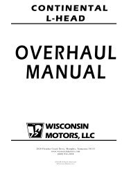
LOCATING LUGS<br />
STAMPED<br />
NUMBERS<br />
SHELL<br />
BEARING<br />
Fig. 32<br />
PLACE OPEN END OF<br />
RING ON PISTON<br />
FIRST AS SHOWN<br />
Fig. 30<br />
~<br />
COMPRESSION<br />
UPPER END OF PISTON<br />
RINGS<br />
|iii~ SCRAPER RING<br />
OIL RING<br />
Fig. 33<br />
OIL<br />
Fig. 31<br />
lug of both bearing halves are on the same side as<br />
illustrated in Fig. 30. Refer to chart, Fig. 34, for<br />
clearance between bearing and crank pin.<br />
The piston skirt is cam.ground to an elliptical contour.<br />
Clearance between the piston and cylinder must<br />
be measured at the center of the thrust face at the<br />
bottom of the piston skirt. Refer to Chart, Fig. 34, for<br />
proper clearance. The thrust faces on the piston skirt<br />
are 90 ° from the axis of the piston pin hole, with the<br />
wide sect)on of the piston skirt toward the maximum<br />
thrust side, or opposite the crankshaft rotation. ,See<br />
Engine Sectional, Fig. 2. The <strong>VG4D</strong> was originally<br />
designed with split-skirt pistons which were mounted<br />
with the split toward the direction of crankshaft rotation<br />
(clockwise facing flywheel end).<br />
In reassembly; be sure piston and connecting rod assemblies<br />
are put back into the same bore from which<br />
they were removed. Use a suitable ring compressor<br />
and stagger the piston ring gaps 90 o apart around the<br />
piston. Oil the pistons, rings, wrist pins, rod bearings and<br />
cylinder walls before assembly.<br />
CAUTION: Identical numbers are stamped on the side of<br />
the rod with its corresponding cap. These numbers must be<br />
on the same side of the connecting rod when mounted in<br />
engine. Be sure that oilhole in connecting rod cap is facing<br />
toward the oil spray nozzle, as illustrated in Fig. 31. Install<br />
new nuts on connecting rod bolts and torque 28-32 foot<br />
pounds.<br />
PISTON RINGS (Fig’s. 32, 33, 34)<br />
If a ring expander tool is not available, install rings<br />
by placing the open end of ring on piston first, as<br />
shown in Fig. 32. Spread ring only far enough to slip<br />
over piston and into correct groove, being careful not<br />
to distort ring. Install bottom ring first and work toward<br />
the head of the piston, installing top ring last.<br />
Each piston has two compression rings, a scraper<br />
ring with expander, and an oil control ring. The outer<br />
diameter of the top compression ring is chrome plated.<br />
Mount scraper ring with scraper edge down, otherwise<br />
oil pumping and excessive oil consumption will result.<br />
See Fig. 33 for the correct ring placement.<br />
CYLINDER<br />
BLOCKS<br />
Clean all dirt and foreign deposits from between the<br />
cylinder fins and manifold ports.<br />
22