
Create successful ePaper yourself
Turn your PDF publications into a flip-book with our unique Google optimized e-Paper software.
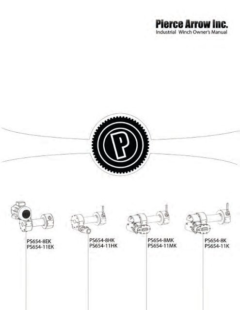
<strong>Industrial</strong> <strong>Winch</strong> Owner’s <strong>Manual</strong> 1
<strong>Industrial</strong> <strong>Winch</strong> Owner’s <strong>Manual</strong><br />
The 654 series worm drive winch is a powerful tool and must be used with extreme care. Deviating from the manual’s instructions may cause personal injury.<br />
You may void your warranty if you do not follow the precautions and guidelines outlined in this manual. Keep this manual in a safe place to reference safety<br />
and installation instructions, maintenance guidelines and operating recommendations.<br />
<strong>Manual</strong> Contents<br />
Shipment Contents.................................................. 2<br />
Safety Precautions.................................................... 2<br />
General Safety Information...................................... 2-3<br />
Operation Recommendations.................................. 3<br />
Mounting.................................................................. 3 - 7<br />
Electrical Installation Recommendations................. 3<br />
Installation Instructions............................................ 3 - 4<br />
Lubrication................................................................ 3<br />
Electrical Connections.............................................. 3 - 4<br />
Operation................................................................. 4<br />
Maintenance............................................................ 4 - 5<br />
Specifications........................................................... 5<br />
Diagrams.................................................................. 8-15<br />
Warranty.................................................................. 16<br />
Shipment Contents<br />
PS654K and PS654MK<br />
1 – <strong>Winch</strong><br />
1 – Remote Control<br />
1 – Clutch Lever<br />
1 – Key<br />
8 – <strong>Winch</strong> Mounting Bolts<br />
8 – 3/8” Lock Washer<br />
1 – Set Screw<br />
1 – Owner’s <strong>Manual</strong><br />
PS654EK<br />
1 – <strong>Winch</strong><br />
1 – Owner’s <strong>Manual</strong><br />
2 – Pierce <strong>Winch</strong> Oil<br />
Recommended Tools<br />
9/16” Wrench or Socket<br />
17” Wrench<br />
Crowbar<br />
Gloves<br />
Safety Glasses<br />
First Aid Kit<br />
Safety Precautions<br />
Dress properly<br />
• DO NOT wear loose fitting clothing or jewelry.<br />
• Tie back long hair.<br />
• Wear leather gloves when handling the wire rope.<br />
• Wear non-skid footwear during winch operation.<br />
• Wear eye and ear protection during operation.<br />
Keep a safe distance<br />
• DO NOT step over or under the wire rope.<br />
• All onlookers must keep away from the work area.<br />
• Never work on or around the winch drum when the winch is operating.<br />
• DO NOT alter your winch in any way. Alterations may weaken the<br />
structural integrity of the winch and void your warranty.<br />
• Operate your winch with an unobstructed view.<br />
• Read the following safety information carefully before attempting to<br />
operate your winch. Keep this manual for future reference.<br />
General Safety Information<br />
DO NOT misuse your winch<br />
2 Pierce Arrow 940-538-5643<br />
PS654HK<br />
1 – <strong>Winch</strong><br />
1 – Clutch Lever<br />
1 – Key<br />
1 – Hydraulic Motor<br />
1 – Motor Coupler<br />
8 – <strong>Winch</strong> Mounting Bolts<br />
2 – ½” x 1 ½” Motor Bolts<br />
8 – 3/8” Lock Washer<br />
2 – 1/2” Lock Washer<br />
2 – 1/4” Set Screw<br />
1 – Owner’s <strong>Manual</strong><br />
• DO NOT lift items vertically. The winch was designed for horizontal use<br />
only.<br />
• DO NOT operate the winch with less than eight wraps on the drum. The<br />
set screw on the drum is not designed to hold pull force of cable.<br />
• Avoid continuous pulls from extreme angles. This will cause the wire<br />
rope to jam as it piles up on one side.<br />
• Use a nylon sling when winching. Hooking the wire rope to itself will<br />
cause considerable damage to the wire rope.<br />
• DO NOT move your vehicle to assist the winch in pulling the load. The<br />
combination of the winch and vehicle pulling could overload the wire<br />
rope and winch.<br />
• Never release the free spool clutch when a load is connected to the<br />
winch.<br />
• DO NOT exceed the pulling limitations of this winch.<br />
• DO NOT shock loads when winching. A shock load occurs when<br />
increased force is suddenly applied to the wire rope.<br />
• DO NOT use your winch as a hoist.<br />
• DO NOT use your winch to lift, support or transport people.<br />
• DO NOT alter the warning instruction labels.<br />
• DO NOT overheat your winch. Use your winch intermittently.<br />
• Only use your winch for direct winching. Do not use your winch for<br />
jerking loads, towing or securing a load. Any damage incurred as a result<br />
of such action will void the warranty.<br />
• DO NOT winch near electrical power lines.<br />
DO NOT abuse the wire rope<br />
• Never carry your winch by the wire rope.<br />
• Never yank the wire rope from the winch.<br />
• Keep the wire rope from heat or sharp edges.<br />
DO NOT overwork your winch<br />
• DO NOT maintain power if the motor stalls.<br />
• DO NOT exceed maximum line pull ratings.<br />
• DO NOT overload your winch’s pulling capacity. We recommend the use<br />
of a pulley block to double line the wire rope on heavy loads.<br />
• DO NOT prolong pulls. The electric winch is designed for intermittent<br />
use only. If the motor becomes very hot stop the winch and let it cool<br />
down for several minutes.<br />
Avoid unintentional starting<br />
• The winch clutch must be disengaged when not in use and fully engaged<br />
when in use. The winch dog will disengage from the drum if the clutch is<br />
not fully engaged.<br />
DISENGAGED<br />
ENGAGED<br />
• The warranty will be voided if the winch is used when not properly<br />
engaged.<br />
• Failure to use the winch without fully engaging the clutch may result in<br />
personal and property damage.<br />
• Power must be disconnected when not in use.<br />
Maintain your winch<br />
• Before use, you must check your winch carefully.<br />
• Damaged equipment must be properly repaired or replaced by the<br />
manufacturer or an authorized service center.<br />
• Inspect and maintain the wire rope and winch frequently.<br />
• Replace frayed rope strands immediately.<br />
• Use only factory approved switches, remote controls and accessories.<br />
• Check the tightness of the mounting bolts and electrical connections<br />
periodically.<br />
Re-spool the wire rope<br />
• Wear leather gloves while re-spooling wire winch rope.
• ATTENTION: DO NOT allow the wire rope to thread through your hand.<br />
• Keep a slight load on the wire rope while re-spooling. Hold the wire<br />
rope with one gloved hand and the remote control in the other.<br />
Operation<br />
Recommendations<br />
• DO NOT attach tow hooks to the winch mount.<br />
• Use a snatch block to double your winch capacity, half the winch speed<br />
and maintain a direct line pull to the center of the rollers.<br />
• Use rated D ring or bow shackles in conjunction with an approved tree<br />
trunk protector to provide a safe anchor point.<br />
• Position blocks under your vehicle’s wheels when winching.<br />
• Lay a heavy blanket or jacket over the wire rope when pulling heavy<br />
loads. Should wire rope failure occur the cloth may help prevent wire<br />
rope backlash.<br />
• Use a crowbar or cable tensioner (PSCT8 or PSCT11) when guiding the<br />
wire rope over the drum. Never use your fingers.<br />
• To reach the maximum rated line pull be sure the input voltage between<br />
the motor terminals is continuously 12 VDC. Note: This winch only<br />
reaches the maximum rated line pull with the first layer of cable around<br />
the drum when pulling the loads.<br />
• Plug in the remote control and engage the clutch before spooling. DO<br />
NOT engage the clutch while the motor is running.<br />
• When using your winch to move a load, place the vehicle transmission<br />
in neutral, set vehicle brake and lock all wheels. The vehicle engine<br />
should be running during winch operation. If winching is performed<br />
with the engine off the battery may be too weak to restart the engine.<br />
• Use chains or straps to secure the load, not your winch cable.<br />
• Stay alert while winching. Stop every meter or five feet to ensure the<br />
wire rope is neatly wound around the drum.<br />
• After winch operation, spool the extended cable tightly around the<br />
drum.<br />
• Always release the load after operation.<br />
• Store the remote control inside your vehicle.<br />
• Inspect the control before use.<br />
• Unless specified, Pierce AC winches are not equipped with free spool.<br />
Electrical<br />
Recommendations<br />
PS654K . PS654MK . PS654EK<br />
ATTENTION: Failure to use a battery disconnect switch<br />
may void your warranty.<br />
• Performance of an electric winch depends entirely upon its power<br />
supply. The winch will draw between 70 to 400 amps depending on the<br />
load. Under heavy pulling, even the largest batteries will become weak.<br />
Always leave the vehicle running when winching. You may also install a<br />
high ampere alternator to improve the winch performance.<br />
• The single wire extending from the winch should be attached to the<br />
positive post of a 12 V battery. The minimum size conductor to use is a<br />
#4 welding lead. A #2 welding leading is highly recommended. <strong>Winch</strong><br />
performance is directly related to conductor size and power supply. A<br />
larger conductor size is always preferable but is required if more than<br />
ten feet is used. Always install a ground cable of at least #4 gauge<br />
from the negative battery post to one of the motor mounting bolts on<br />
the winch. DO NOT connect the ground wire to any of the electrical<br />
terminals on the motor.<br />
• A good ground wire is very important for successful winching. Both the<br />
winch and the solenoid assembly must be grounded. A bad ground may<br />
cause the winch not to run at all. Run the ground wire from one of the<br />
motor mounting bolts to the negative terminal on your battery.<br />
• A battery disconnect switch (PS025) is highly recommended when<br />
installing the winch. The operator or user must use some type of<br />
disconnect switch with a capacity of 400 amps when installing and<br />
operating the winch. The winch is to be left disconnected when not in<br />
use or unattended. Installing the winch directly to the battery supply<br />
will void the warranty.<br />
• Make sure all cables are tight on both the ring connector and on the<br />
stud where they are attached. Care must be taken when installing a<br />
cable on the motor terminals. Nuts closest to the motor housing should<br />
be held with a wrench to prevent the stud from turning inside the<br />
motor. See page 6 for the wiring diagram.<br />
• DO NOT continue to winch when the battery power is low. Low voltage<br />
and amperage will cause the solenoids and the motor to overheat.<br />
Running the winch with a weak battery will often cause the points of the<br />
solenoids to become welded together.<br />
Installation<br />
PS654K and PS654MK<br />
Mounting<br />
1. Before installation ensure the mounting frame in use is capable of<br />
withstanding the winch’s rated capacity.<br />
2. Ensure the motor, drum and gear housing is properly aligned.<br />
3. The clutch housing must be 1/16”- 1/8” from the drum.<br />
4. Mount to a flat surface using grade 5 or better bolts that are 3/8” thick<br />
and lock washers. Your mounting plate must be six millimeters or 1/4”<br />
thick.<br />
5. All eight bolts should penetrate the mounting pads on the main gear<br />
housing and clutch housing exactly 3/4” inches deep.<br />
LUBRICATION<br />
1. This winch is pre-greased and will not require oil. If the gears are<br />
changed at any time use 20% Lucus HD oil stabilizer and 80% 15w-40 oil.<br />
2. Lubricate both grease zerts on the clutch lever every six months with<br />
automotive grease (Mystic JT-6).<br />
Electrical CONNECTIONS<br />
1. Connect the power cable from the solenoid to a positive power source.<br />
2. Wire a 4 gauge ground (not supplied) from the winch motor directly to a<br />
negative terminal of the battery.<br />
PS654EK<br />
Mounting<br />
1. Your PS654 winch is shipped fully assembled, mounted, wired and oiled.<br />
LUBRICATION<br />
1. You must lubricate your new winch before use.<br />
2. Flip the winch up-side-down.<br />
3. Empty one Pierce <strong>Winch</strong> Oil container into the main gear housing and<br />
one container into the transfer housing.<br />
4. NOTE: A small amount of oil see page is normal due to vent plugs. The<br />
motor supplied is not waterproof and should be covered if installed<br />
outdoors.<br />
Electrical CONNECTIONS<br />
1. Connect the plug to an outlet with a dedicated 20 amp. breaker.<br />
PS654HK<br />
Mounting<br />
1. Before installation ensure the mounting frame in use is capable of<br />
withstanding the winch’s rated capacity.<br />
2. Ensure the motor, drum and gear housing is properly aligned.<br />
3. The clutch housing must be 1/16”-1/8” from the drum.<br />
4. Mount to a flat surface using grade 5 or better bolts that are 3/8” thick<br />
and lock washers.<br />
5. Your mounting plate must be six millimeters or 1/4” thick. If a heavier<br />
mounting plate is used the bolts must be lengthened accordingly.<br />
6. All eight bolts should penetrate the mounting pads on the main gear<br />
housing and clutch housing by 3/4”.<br />
LUBRICATION<br />
1. This winch is pre-greased and will not require oil. If the gears are<br />
changed at any time use 20% Lucus HD oil stabilizer and 80% 15w-40 oil.<br />
2. Lubricate both grease zerts on the clutch lever every six months with<br />
automotive grease (Mystic JT-6).<br />
Installing the Hydraulic Motor Coupler<br />
1. Place the larger end of the coupler on the motor shaft.<br />
2. Tighten the set screw in the coupler on the motor shaft.<br />
3. Fit the motor and coupler to the winch ensuring that the key stays on<br />
the worm shaft.<br />
4. Lastly, tighten the two bolts holding the hydraulic motor to the hydraulic<br />
housing coupler.<br />
5. If the hydraulic motor is not running freely when operating, loosen the<br />
<strong>Industrial</strong> <strong>Winch</strong> Owner’s <strong>Manual</strong> 3
two large bolts one complete turn, briefly run the winch, and re-tighten<br />
the two bolts.<br />
hose CONNECTIONS<br />
1. Connect two 1/2 in. NPT hydraulic hoses from the winch to the hydraulic<br />
power source.<br />
Operation<br />
The first use of your winch must be a test run during a non-recovery<br />
situation. During this trial run begin to recognize the sound of a steady pull, a<br />
heavy pull, load jerking or shifting.<br />
Spooling the wire rope<br />
1. Wear leather gloves while spooling. ATTENTION: DO NOT allow the wire<br />
rope to thread through your hand.<br />
2. Unwind the wire rope carefully along the floor to avoid kinking.<br />
3. Place the end of the wire rope in to the hole on the side of the drum.<br />
The wire rope will protrude ½”- 1”. Tighten the set screw.<br />
4. Keep a slight load on the wire rope while spooling.<br />
5. Using the remote control, wrap the wire rope on to the drum until<br />
the load is recovered. Make sure the wire rope lays smoothly on to<br />
the drum without spacing or overlapping using a crowbar or cable<br />
tensioner.<br />
Test Run<br />
1. Spool the wire rope until the red mark appears at five wraps.<br />
2. Under a load of 500 lbs (230 kg) re-spool the wire rope. This will stretch<br />
the new wire rope and create a tight wrap around the drum.<br />
PS654K . PS654MK<br />
1. Place the transmission in neutral and apply the parking brake or lock the<br />
wheels.<br />
2. Spool the winch cable and connect to an anchor point.<br />
3. Engage the clutch by shifting it into the IN position. Use force to engage<br />
the clutch. If the freewheel easily moves IN and Out of position then<br />
the winch is not fully enegaged. NOTE: When the clutch is engaged your<br />
load will be securely held until the remote is used.<br />
4. Check cable rigging before proceeding.<br />
5. Plug in the winch remote control located on the solenoid assembly.<br />
NOTE: To ensure safe operation, it is recommended that winch<br />
operation take place from the driver’s position.<br />
6. Start vehicle engine, select neutral or park and maintain idle engine<br />
speed.<br />
7. Using the remote control, press IN or OUT until the vehicle has been<br />
retrieved. Regularly check to ensure the cable is winding onto the drum<br />
evenly.<br />
8. Secure your load using straps or chains.<br />
9. Re-spool the wire rope after the winch operation is completed.<br />
PS654HK<br />
1. Apply the parking brake or lock the wheels.<br />
2. Spool the winch cable and connect to an anchor point.<br />
3. Engage the clutch by shifting it into the IN position. Use force to engage<br />
the clutch. If the freewheel easily moves IN and Out of position then<br />
the winch is not fully enegaged. NOTE: When the clutch is engaged your<br />
load will be securely held until the remote is used.<br />
4. Check cable rigging before proceeding.<br />
5. Secure the load using chains or straps, not your winch wire rope.<br />
6. To ensure safe operation, it is recommended that winch operation take<br />
place from the driver’s position. Re-spool the wire rope after the winch<br />
operation is completed.<br />
PS654EK<br />
1. Turn on the breaker.<br />
2. Spool the cable and connect to an anchor point.<br />
3. Check the cable rigging before proceeding.<br />
4. Re-spool the wire rope after the winch operation is completed.<br />
Maintenance<br />
PS654K . PS654MK<br />
1. <strong>Winch</strong>es are pre-greased and do not require additional lubrication. If<br />
the gears are changed at any time use 20% Lucus HD oil stabilizer and<br />
80% 15w-40 oil.<br />
2. Check the grease fittings.<br />
3. Check all the electrical connections to ensure good contact and no<br />
corrosion. Replace as needed.<br />
4. Check all accessible bolts to ensure they are tightly bound.<br />
5. Check the wire rope for kinks or frays. Replace with a wire rope of equal<br />
strength.<br />
6. Check the clutch dog, clutch yoke and drum for damage.<br />
7. Contact your service center or the manufacturer before servicing your<br />
winch.<br />
PS654HK<br />
1. <strong>Winch</strong>es are pre-greased and do not require additional lubrication. If<br />
the gears are changed at any time use 20% Lucus HD oil stabilizer and<br />
80% 15w-40 oil.<br />
2. Check the grease fittings.<br />
3. Check the hose connections to ensure good contact and no leaks.<br />
Replace as needed.<br />
4. Check all accessible bolts to ensure they are tightly bound.<br />
5. Check the wire rope for kinks or frays. Replace with a wire rope of equal<br />
strength.<br />
6. Check the clutch dog, clutch yoke and drum for damage.<br />
7. Contact your service center or the manufacturer before servicing your<br />
winch.<br />
PS654EK<br />
1. Check oil levels.<br />
2. Check all electrical connections.<br />
3. Check all accessible bolts to ensure they are tightly bound.<br />
4. Check the wire rope for kinks or frays. Replace with a wire rope of equal<br />
strength.<br />
5. Contact your service center or the manufacturer before servicing your<br />
winch.<br />
Frequently Asked Questions<br />
Q: Can I increase the line speed of my worm drive winch<br />
A: Yes, but you will lose about half of your pulling power. On electric winches,<br />
a simple exchange of gears can provide up to a 50% line speed increase, and<br />
on hydraulic winches, you can change your motor to one with a different<br />
displacement.<br />
Q: How much wire rope will my winch hold<br />
A: The 8” drum will hold 100’ of 3/8” cable, and the 11” drum will hold 125’.<br />
Q: Can I use a fuse to protect my winch and vehicle<br />
A: Use of a fuse, or some circuit interrupting device, is highly recommended.<br />
A better idea would be to use a breaker. High amp fuses are costly, and<br />
amperage spikes are not uncommon when winching. A breaker that will<br />
throw at 400 amps is ideal. It may cost more in the beginning, but will<br />
far outweigh the cost of replacing 400 amp fuses. Cut-off switches are<br />
less costly, while not preventing amperage spikes, they will allow you to<br />
disconnect power in the event of a short in the winch.<br />
Q: Does my winch need it’s own battery<br />
A: Most electrical systems aren’t designed for accessories like a winch. Your<br />
winch will work with your OEM battery, but there is a heavy amperage load<br />
while winching. Think of the amperage to start your truck. It would be like<br />
starting your truck the whole time you are winching. It is a good idea to use a<br />
deep cycle battery, or even add a battery to your system just for your winch if<br />
you can. Just make sure your charging system can handle the load as well.<br />
Q: How much and what type of oil does my winch need<br />
A: Each housing takes 6-8 ounces of oil. We recommend using our special<br />
blend of Pierce <strong>Winch</strong> Oil. The viscosity range depends on use and location.<br />
You need a minimum of 30W but in some regions a heavy gear oil is too<br />
thick.<br />
Q: How can I test my motor<br />
A: Disconnect all three wires from your motor, making sure to mark<br />
which wire is which for reconnection. Supply a solid ground connection<br />
to the motor casing. Next, connect 12V to field terminal, F1. Take a long<br />
screwdriver, or similar tool, and make contact between field terminal, F2,<br />
and the armature post. This should bridge the electrical connection and start<br />
your motor. Now do this with the opposite field terminal. Connect power<br />
to F2, then make contact from F1 to the armature post. Again, your motor<br />
should run. See diagram on page 5. If the motor is unresponsive to both tests<br />
the motor must be replaced with a PS534H Pierce 12V motor.<br />
4 Pierce Arrow 940-538-5643
Specifications<br />
ELECTRIC WINCHES<br />
Model Description Capacity Voltage Ampere Dimensions Speed Weight Motor Ratio Rotation Gear<br />
Train<br />
PS654-8K<br />
PS654-11K<br />
PS654-8MK<br />
PS654-11MK<br />
9,000 lb<br />
DC<br />
8” drum<br />
9,000 lb<br />
DC<br />
11” drum<br />
12,500 lb<br />
DC<br />
8” drum<br />
12,500 lb<br />
DC<br />
11” drum<br />
4.5 T 12 V 400 amps<br />
with load<br />
4.5 T 12 V 400 amps<br />
with load<br />
6 T 12 V 400 amps<br />
with load<br />
6 T 12 V 400 amps<br />
with load<br />
Cable capacity: 3/8” x 100’<br />
Unit: 16 1/4” x 13 1/2”<br />
Drum 3.5” x 8”<br />
Cable capacity: 3/8” x 125’<br />
Unit: 19 1/4” x 13 1/2”<br />
Drum 3.5” x 11”<br />
Cable capacity: 3/8” x 100’<br />
Unit: 16 1/4” x 8” x 13 1/2”<br />
Drum 3.5” x 8”<br />
Cable capacity: 3/8” x 125’<br />
Unit: 19 1/4” x 8” x 13 1/2”<br />
Drum 3.5” x 11”<br />
14 fpm 88 lbs 1.5 hp 470:1 CW/CCW Worm<br />
Gear<br />
14 fpm 92 lbs 1.5 hp 470:1 CW/CCW Worm<br />
Gear<br />
9 fpm 88 lbs 1.5 hp 520:1 CW/CCW Worm<br />
Gear<br />
9 fpm 94 lbs 1.5 hp 520:1 CW/CCW Worm<br />
Gear<br />
Clutch<br />
Dog<br />
Dog<br />
Dog<br />
Dog<br />
Brake<br />
Worm<br />
Gear<br />
Worm<br />
Gear<br />
Worm<br />
Gear<br />
Worm<br />
Gear<br />
PS654-8EK<br />
7,500 lb<br />
AC<br />
8” drum<br />
3.75 T 110/220 V 400 amps<br />
with load<br />
Cable capacity: 3/8” x 100’<br />
Unit: 26” x 15” x 17 1/2”<br />
Drum 3.5” x 8”<br />
4 fpm 160 lbs 1.5 hp 460:1 CW/CCW Worm<br />
Gear<br />
Dog/<br />
Locked<br />
Worm<br />
Gear<br />
PS654-11EK<br />
7,500 lb<br />
AC<br />
11” drum<br />
3.75 T 110/220 V 400 amps<br />
with load<br />
Cable capacity: 3/8” x 125’<br />
Unit: 26” x 15” x 17 1/2”<br />
Drum 3.5” x 11”<br />
4 fpm 160 lbs 1.5 hp 460:1 CW/CCW Worm<br />
Gear<br />
Dog/<br />
Locked<br />
Worm<br />
Gear<br />
HYDRAULIC WINCHES<br />
Model Description Capacity Max Oil<br />
Flow<br />
PS654-8HK<br />
PS654-11HK<br />
9,000 lb<br />
Hydraulic<br />
8” drum<br />
9,000 lb<br />
Hydraulic<br />
11” drum<br />
Motor Test Procedure<br />
Pressure Dimensions Speed Weight Motor Ratio Rotation Gear<br />
Train<br />
4.5 T 15 gpm 2,000 psi Cable capacity: 3/8” x 100’<br />
Unit: 16 1/4” x 8” x 13 1/2”<br />
Drum 3.5” x 8”<br />
4.5 T 15 gpm 2,000 psi Cable capacity: 3/8” x 125’<br />
Unit: 19 1/4” x 8” x 13 1/2”<br />
Drum 3.5” x 11”<br />
18 fpm 67 lbs 4.8 cu.<br />
in/rev<br />
18 fpm 67 lbs 4.8 cu.<br />
in/rev<br />
60:1 CW/CCW Worm<br />
Gear<br />
60:1 CW/CCW Worm<br />
Gear<br />
If your motor is unresponsive please follow these steps to test the power. If the test proves unsuccessful, your motor will need to be replaced with a PS534H.<br />
Clutch<br />
Dog<br />
Dog<br />
Brake<br />
Worm<br />
Gear<br />
Worm<br />
Gear<br />
STEP 1: Remove any wires connected to A, F1 and F2.<br />
STEP 2: Apply power to F2. Connect terminal A to F1 with a screwdriver.<br />
STEP 3: Apply power to F1. Connect terminal A to F2 with a screwdriver.<br />
NOTE: The motor must be grounded to the motor casing not the electrical terminals.<br />
+<br />
STEP 2 .................................. STEP 3 .................................<br />
-<br />
+<br />
Ground<br />
12V<br />
Mount ground to<br />
motor casing.<br />
- -<br />
Mount ground to<br />
motor casing.<br />
F1<br />
F2<br />
Field 1<br />
Field 2<br />
A<br />
F1<br />
A<br />
F1<br />
A<br />
Armature<br />
F2<br />
F2<br />
PS534H<br />
12V Motor<br />
+<br />
Check out the winch<br />
maintenance video on<br />
YouTube.<br />
<strong>Industrial</strong> <strong>Winch</strong> Owner’s <strong>Manual</strong> 5
Electrical Connections: Replacement Parts<br />
PS528C SOLENOID ASSEMBLY AND<br />
PS534H <strong>PIERCE</strong> 12V MOTOR<br />
iring<br />
Wiring<br />
Diagram<br />
Diagram<br />
In the event that a solenoid assembly, motor, male or<br />
female ROUND plug requires SOLENOID replacement ASSEMBLY please use the diagrams<br />
WIRING CHART PS528C MOTOR<br />
D SOLENOID<br />
below<br />
ASSEMBLY<br />
to connect the wires.<br />
WIRING CHART Connect the wires PS528C to the MOTOR Use the Pierce PS534H or<br />
+<br />
+<br />
A<br />
A<br />
1<br />
1<br />
2<br />
Connect the wires to the corresponding Use signs. the Pierce PS534H or PS534CH Motor on the PS528C<br />
corresponding signs.<br />
A<br />
2<br />
Armature Post<br />
1 Field 1<br />
2 Field 2<br />
+ 12V<br />
A<br />
PS534CH Motor on the PS528C round solenoid assembly.<br />
Armature Post<br />
round solenoid assembly.<br />
1 Field 1<br />
2 Field 2<br />
+ 12V<br />
A 2<br />
A 2 1<br />
1<br />
PS534H<br />
Pierce 12V Motor<br />
PS534H<br />
Pierce 12V Motor<br />
8C<br />
ND SOLENOID<br />
MBLY<br />
PS528C<br />
ROUND SOLENOID<br />
ASSEMBLY<br />
P215F AND P215M MALE AND FEMALE PLUG<br />
This diagram depicts standard wiring for Pierce PS654<br />
industrial winches and remotes. 18 - 14 gauge wire is<br />
highly recommended for hook up.<br />
wiring.<br />
Wiring Diagram<br />
REMOTE CONTROL PLUGS<br />
WIRING DESCRIPTION<br />
WIRING DESCRIPTION<br />
This chart depicts wiring<br />
from a Pierce PS528C round<br />
solenoid assembly to the<br />
Pierce PS534H or PS534CH<br />
This chart depicts wiring<br />
from a Pierce PS528C round<br />
solenoid assembly to the<br />
Pierce PS534H or PS534CH<br />
12V PRODUCT motor. DESCRIPTION<br />
Use #2 or #4 gauge<br />
12V motor. Use #2 or #4 gauge wiring. ROUND SOLENOID ASSEMBLY<br />
CATEGORY<br />
PART NUMBER<br />
CATEGORY<br />
WINCH<br />
PART NUMBER<br />
PARTS PS528C<br />
WINCH PARTS PS528C<br />
PRODUCT DESCRIPTION<br />
ROUND SOLENOID ASSEMB<br />
CONTACT<br />
Pierce Arrow Inc.<br />
549 U.S. HWY 287 S.<br />
Henrietta, TX 76365<br />
www.piercearrow.us<br />
1-800-658-6301<br />
CONTACT<br />
Pierce Arrow Inc.<br />
549 U.S. HWY 287<br />
Henrietta, TX 763<br />
www.piercearrow<br />
1-800-658-6301<br />
F1<br />
P215F<br />
F2<br />
12V<br />
F1<br />
12V<br />
F2<br />
6 Pierce Arrow 940-538-5643<br />
P215M<br />
WIRING DESCRIPTION<br />
This diagram depicts standard<br />
wiring for Pierce PS654<br />
industrial winches and remot
Mounting Patterns<br />
These mounting patterns are intended to be used with Pierce pre-drilled and notched 1/4” x 2 “ x 2” angle iron mounting brackets<br />
angle iron mounts (PT037). Use these mounts to recess your winch in a semi-hidden application or build your own custom mount.<br />
All measurements are center-to-center.<br />
ps654-k -mk -hk 8” DRUM<br />
1.5” 9.075” 1.5”<br />
1” dia.<br />
1.5”<br />
ps654-k -mk -hk 11” DRUM<br />
1.5” 9.075” 1.5”<br />
1” dia.<br />
1.5”<br />
ps654-ek 8” DRUM<br />
0.8” 1.55”<br />
5.65”<br />
1.525” dia.<br />
1”<br />
0.95”<br />
0.95”<br />
ps654-ek 11” DRUM<br />
0.8” 1.55”<br />
5.65”<br />
1.525” dia.<br />
1”<br />
0.95”<br />
0.95”<br />
USE<br />
DON’T USE<br />
<strong>Industrial</strong> <strong>Winch</strong> Owner’s <strong>Manual</strong> 7
PS654-K<br />
9,000 lb. Electric <strong>Winch</strong><br />
PS508<br />
PS508W<br />
PS509<br />
PS510<br />
PS512<br />
PS513<br />
PS514<br />
PS516<br />
PS517<br />
PS518<br />
PS519A<br />
PS520<br />
PS534H<br />
PS536<br />
PS539<br />
PS540<br />
PS541<br />
PS542<br />
PS543<br />
PS544<br />
PS546<br />
PS549<br />
PS551<br />
PS552<br />
PS554<br />
PS55511<br />
PS5558<br />
PS556A<br />
PS557<br />
PS558<br />
PS559<br />
PS560<br />
PS562VP<br />
PS563<br />
PS56411<br />
PS5648<br />
PS565<br />
PS567<br />
PS5671<br />
PS568<br />
PS569<br />
PS570<br />
PS571<br />
PS572<br />
PS573<br />
PS515<br />
Motor Transfer Key<br />
Motor Woodruff Key<br />
.25” x 1.75 “ Mounting Screw<br />
Motor Mount Screw<br />
Small External Snap Ring Retainer<br />
Idler Gear<br />
Transfer Gear<br />
Long PW Key<br />
Power Shaft<br />
Screw Set for Motor Gear<br />
Motor Drive Gear<br />
Transfer Housing Cover<br />
12V Motor<br />
Worm Gasket<br />
Large External Snap Ring Retainer<br />
.055 Thrust Washer<br />
Medium External Snap Ring Retainer<br />
Drag Brake Spring<br />
Nylon Drag Brake<br />
3/8 in. Lock Washer<br />
<strong>Winch</strong> Bearing<br />
Drum Set Screw<br />
Grease Fitting<br />
Main Gear Housing Cover<br />
Main Gear<br />
11 in. Shaft<br />
8 in. Shaft<br />
Motor Seal<br />
Open Bearing Cap<br />
Worm Gear<br />
1/4 in. A/N Washer<br />
1/4 in. Allen Head Cap Screw<br />
3/8 in. Pipe Thread Vent<br />
Main Gear Housing<br />
11 in. Drum<br />
8 in. Drum<br />
Clutch Dog<br />
Shift Yoke<br />
Shift Yoke Shaft Spring<br />
Drum Bushing<br />
Clutch Housing<br />
Clutch Shaft<br />
Handle Key<br />
Clutch Handle Set Screw<br />
Clutch Lever<br />
Spacer<br />
8 Pierce Arrow 940-538-5643
<strong>Industrial</strong> <strong>Winch</strong> Owner’s <strong>Manual</strong> 9
PS654-MK<br />
12,500 lb. Electric <strong>Winch</strong><br />
PS508<br />
PS508W<br />
PS509<br />
PS512<br />
PS514<br />
PS515<br />
PS518<br />
PS519A<br />
PS520<br />
PS521<br />
PS522<br />
PS523<br />
PS536<br />
PS541<br />
PS542<br />
PS543<br />
PS546<br />
PS549<br />
PS551<br />
PS552<br />
PS553<br />
PS554<br />
PS55511<br />
PS5558<br />
PS556<br />
PS557<br />
PS558<br />
PS559<br />
PS560<br />
PS561<br />
PS562VP<br />
PS563<br />
PS56411<br />
PS5648<br />
PS565<br />
PS567<br />
PS5671<br />
PS568<br />
PS569<br />
PS570<br />
PS571<br />
PS572<br />
PS573<br />
PS575<br />
PS510<br />
PS544<br />
Motor Transfer Key<br />
Motor Woodruff Key<br />
.25” x 1.75 “ Mounting Screw<br />
Small External Snap Ring Retainer<br />
Transfer Gear<br />
Spacer<br />
Screw Set for Motor Gear<br />
Gear New Motor Drive<br />
Transfer Housing Cover<br />
<strong>Winch</strong> Plug<br />
Transfer Housing Gasket<br />
Transfer Housing Gear<br />
Worm Gasket<br />
Medium External Snap Ring Retainer<br />
Drag Brake Spring<br />
Nylon Drag Brake<br />
<strong>Winch</strong> Bearing<br />
Drum Set Screw<br />
Grease Fitting<br />
Main Gear Housing Cover<br />
Main Gear Gasket<br />
Main Gear<br />
11 in. Shaft<br />
8 in. Shaft<br />
Motor Seal<br />
Cap Bearing Open<br />
Worm Gear<br />
1/4 in. A/N Washer<br />
1/4 in. Screw Head Allen Head<br />
Closed Bearing Cap<br />
3/8 in. Thread Pipe Vent<br />
Main Gear Housing<br />
11 in. Drum<br />
8 in. Drum<br />
Clutch Dog<br />
Shift Yoke<br />
Shift Yoke Shaft Spring<br />
Drum Bushing<br />
Clutch Housing<br />
Clutch Shaft<br />
Handle Key<br />
Clutch Handle Screw Set<br />
Clutch Lever<br />
Planetary Gear<br />
Motor Mount Screw<br />
3/8 in. Lock Washer<br />
10 Pierce Arrow 940-538-5643
<strong>Industrial</strong> <strong>Winch</strong> Owner’s <strong>Manual</strong> 11
PS654-HK<br />
9,000 lb. Hydraulic <strong>Winch</strong><br />
P004<br />
PS508<br />
PS509<br />
PS510H<br />
PS536<br />
PS541<br />
PS542<br />
PS543<br />
PS544H<br />
PS546<br />
PS549<br />
PS551<br />
PS552<br />
PS553<br />
PS554<br />
PS55511<br />
PS5558<br />
PS556<br />
PS557<br />
PS558<br />
PS559<br />
PS560<br />
PS561<br />
PS562VP<br />
PS563<br />
PS56411<br />
PS5648<br />
PS565<br />
PS572<br />
PS5671<br />
PS568<br />
PS569<br />
PS570<br />
PS571<br />
PS572<br />
PS573<br />
PS577<br />
PS5771<br />
PS5772<br />
4.8 cu. in. Hydraulic Motor<br />
Key Straight Transfer Motor<br />
.25” x 1.75 “ Mounting Screw<br />
Mounting Bolt for Hydraulic Motor<br />
Worm Gasket<br />
Medium External Snap Ring Retainer<br />
Drag Brake Spring<br />
Nylon Drag Brake<br />
Hydraulic Motor Locking Washer<br />
<strong>Winch</strong> Bearing<br />
Drum Set Screw<br />
Grease Fitting<br />
Main Gear Housing Cover<br />
Main Gear Gasket<br />
Main Gear<br />
11 in. Shaft<br />
8 in. Shaft<br />
Motor Seal<br />
Cap Bearing Open<br />
Worm Gear<br />
1/4 in. A/N Washer<br />
1/4 in. Screw Head Allen Head<br />
Closed Bearing Cap<br />
3/8 in. Thread Pipe Vent<br />
Main Gear Housing<br />
11 in. Drum<br />
8 in. Drum<br />
Clutch Dog<br />
Shift Yoke<br />
Shift Yoke Shaft Spring<br />
Drum Bushing<br />
Clutch Housing<br />
Clutch Shaft<br />
Handle Key<br />
Clutch Handle Screw Set<br />
Clutch Lever<br />
Hydraulic Adapter<br />
Hydraulic Motor Coupling<br />
Woodruff Key<br />
12 Pierce Arrow 940-538-5643
<strong>Industrial</strong> <strong>Winch</strong> Owner’s <strong>Manual</strong> 13
PS654-EK<br />
7,500 or 11,000 lb. AC <strong>Winch</strong><br />
P003NA<br />
PS508<br />
PS508W<br />
PS509<br />
PS510<br />
PS512<br />
PS514<br />
PS515<br />
PS518<br />
PS519A<br />
PS520<br />
PS522<br />
PS523<br />
PS536<br />
PS539<br />
PS540<br />
PS541<br />
PS542<br />
PS543<br />
PS544<br />
PS546<br />
PS551<br />
PS553<br />
PS554<br />
PS55511<br />
PS5558<br />
PS556<br />
PS558<br />
PS559<br />
PS560<br />
PS561<br />
PS56411<br />
PS5648<br />
PS565<br />
PS568<br />
PS575<br />
PSS110<br />
Aluminum Adapter<br />
Motor Transfer Key<br />
Motor Woodruff Key<br />
.25” x 1.75 “ Mounting Screw<br />
Motor Mount Screw<br />
Small External Snap Ring Retainer<br />
Transfer Gear<br />
Spacer<br />
Set Screw for Motor Gear<br />
Gear New Motor Drive<br />
Transfer Housing Cover<br />
Transfer Housing Gasket<br />
Transfer Housing Gear<br />
Worm Gasket<br />
Large External Snap Ring Retainer<br />
.055 Thrust Washer<br />
Medium External Snap Ring Retainer<br />
Drag Brake Spring<br />
Nylon Drag Brake<br />
3/8 in. Lock Washer<br />
<strong>Winch</strong> Bearing<br />
Grease Fitting<br />
Main Gear Gasket<br />
Main Gear<br />
11 in. Shaft<br />
8 in. Shaft<br />
Motor Seal<br />
Worm Gear<br />
1/4 in. A/N Washer<br />
1/4 in. Allen Head Cap Screw<br />
Closed Bearing Cap<br />
11 in. Drum<br />
8 in. Drum<br />
Clutch Dog<br />
Drum Bushing<br />
Planetary Gear<br />
110 VAC Motor<br />
14 Pierce Arrow 940-538-5643
<strong>Industrial</strong> <strong>Winch</strong> Owner’s <strong>Manual</strong> 15
Pierce Arrow Product Limited Warranty<br />
Pierce Arrow Inc. warrants to the original purchaser only (whether a wholesale, OEM or retail customer) that<br />
the goods, equipment, and merchandise manufactured by Pierce Arrow are free from defects in material and<br />
workmanship. The Pierce Arrow limited warranty on parts covers such items for a period of one year on mechanical<br />
and electrical from the date of shipment by Pierce Arrow. All warranties cover only the product or product parts, and<br />
are nontransferable.<br />
OBTAINING WARRANTY SERVICE<br />
Pierce Arrow must be notified promptly in writing, about the defect before any means of repair have been made.<br />
The merchandise must be delivered by the purchaser to Pierce Arrow in Henrietta, Texas at the purchaser’s expense.<br />
Pierce Arrow reserves the right to repair or replace the merchandise proved to be defective. The purchaser is<br />
responsible for the cost of repairs made by Pierce Arrow if the repairs are not covered by the Pierce Arrow warranty.<br />
EXCLUSIONS<br />
The Pierce Arrow warranty is not intended to cover normal maintenance parts, including but not limited to: wear<br />
pads, bushings, mud flaps, fender flares, light bulbs, oil filters, wire rope (winch cable), oil leakage and remote<br />
holdings. Nor is the warranty intended to cover any change or defect due to accident; misuse; improper, inadequate or<br />
unauthorized repair; failure to provide maintenance or uses for which the equipment was not intended; and normal<br />
deterioration due to weather or road conditions. Reference the owner’s manual for safety, installation, operation and<br />
maintenance guidelines.<br />
The warranty does not bear the cost of labor, transportation, shipping damages, claimed down time, loss of profit or<br />
goodwill, or any other special, incidental, indirect, or consequential damages, concerning or related to any product or<br />
part, whether based upon negligence, strict liability, breach of contract, breach of warranty, misrepresentation, or any<br />
other legal theory.<br />
Merchandise sold by Pierce Arrow, but not manufactured by it, is not warranted by Pierce Arrow and is subject to the<br />
manufacturer’s warranty only. The manufacturer’s warranty is available upon request.<br />
Pierce Arrow makes no warranty, expressed or implied, to finished products manufactured or supplied by other<br />
manufacturers, and supplied from Pierce Arrow to the purchaser, including but not limited to, any vehicle to which our<br />
products is affixed to, and any accessories.<br />
Merchandise manufactured by Pierce Arrow is not designed or intended for the movement of people and are not to<br />
be used in the operation of elevators or other improper uses. Any improper use of the product may void the warranty.<br />
Please contact Pierce Arrow with any questions:<br />
Pierce Arrow Inc.<br />
549 U.S. Highway 287 S.<br />
Henrietta, Texas 76365<br />
(toll free) 800-658-6301<br />
P: 940-538-5643<br />
F: 940-538-4382<br />
www.piercearrow.us<br />
Check out the winch<br />
maintenance video on<br />
YouTube.<br />
16 Pierce Arrow 940-538-5643