Emergency Lighting Fixture Installation Instructions (EMP)
Emergency Lighting Fixture Installation Instructions (EMP)
Emergency Lighting Fixture Installation Instructions (EMP)

Create successful ePaper yourself
Turn your PDF publications into a flip-book with our unique Google optimized e-Paper software.
INSTALLATION INSTRUCTIONS<br />
EMERGENCY LIGHTING FIXTURE<br />
Document CI298X01R0 Date 11/29/05<br />
Drawing/Page CPG DCR # 05-350<br />
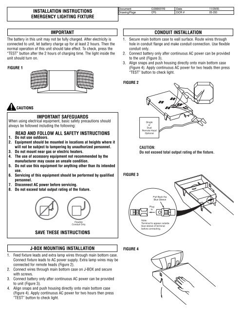
IMPORTANT<br />
The battery in this unit may not be fully charged. After electricity is<br />
connected to unit, let battery charge up for at least 2 hours. Then the<br />
normal operation of this unit should take effect. To check, press the<br />
“TEST” button after the 2 hours of charging time. The light inside the<br />
unit should turn on.<br />
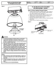
FIGURE 1<br />
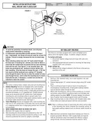
CONDUIT INSTALLATION<br />
1. Secure main bottom case to wall surface. Route wires through<br />
hole in conduit flange and make conduit connection. Use flexible<br />
conduit only.<br />
2. Connect battery only after continuous AC power can be provided<br />
to the unit (Figure 3).<br />
3. Align snaps and push housing directly onto main bottom case<br />
(Figure 4). Apply continuous AC power for two heads then press<br />
“TEST” button to check light.<br />
FIGURE 2<br />
CAUTIONS<br />
IMPORTANT SAFEGUARDS<br />
When using electrical equipment, basic safety precautions should<br />
always be followed including the following:<br />
READ AND FOLLOW ALL SAFETY INSTRUCTIONS<br />
1. Do not use outdoors.<br />
2. Equipment should be mounted in locations at heights where it<br />
will not be subject to tampering by unauthorized personnel.<br />
3. Do not mount near gas or electric heaters.<br />
4. The use of accessory equipment not recommended by the<br />
manufacturer may cause an unsafe condition.<br />
5. Do not use this equipment for anything other than its intended<br />
use.<br />
6. Servicing of this equipment should be performed by qualified<br />
personnel.<br />
7. Disconnect AC power before servicing.<br />
8. Do not exceed total output rating of the fixture.<br />
FIGURE 3<br />
Single<br />
or<br />
Dual<br />
Remote Head<br />
Optional<br />
CAUTION:<br />
Do not exceed total output rating of the fixture.<br />
Pull Back the<br />
Blue Sleeve<br />
Plug<br />
In<br />
Flexible<br />
Conduit Only<br />
SAVE THESE INSTRUCTIONS<br />
Note:<br />
Terminal to appear outside<br />
blue sleeve of terminal<br />
before connecting.<br />
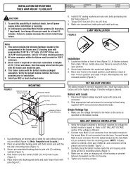
J-BOX MOUNTING INSTALLATION FIGURE 4<br />
1. Feed fixture leads and extra lamp wires through main bottom case.<br />
Connect fixture leads to AC power supply. Extra lamp wires may be<br />
connected for remote heads (Figure 2).<br />
2. Connect wires through main bottom case on J-BOX and secure<br />
with screws.<br />
3. Connect battery only after continuous AC power can be provided<br />
to unit (Figure 3).<br />
4. Align snaps and push housing directly onto main bottom case<br />
(Figure 4). Apply continuous AC power for two hours then press<br />
“TEST” button to check light.
INSTALLATION INSTRUCTIONS<br />
EMERGENCY LIGHTING FIXTURE<br />
Document CI298X01R0 Date 11/29/05<br />
Drawing/Page CPG DCR # 05-350<br />
OPERATION<br />
1. During an electrical power failure, the lamps will automatically<br />
come on for a minimum of 90 minutes.<br />
2. To test this unit, be sure to charge correctly with AC power supply<br />
for 2 hours when first installing then depress the test switch. The<br />
emergency lamps will illuminate. When the switch is released, the<br />
lamps will go off.<br />
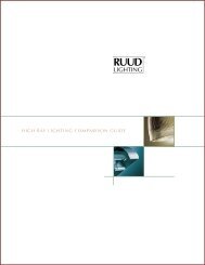
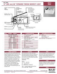
FIGURE 5<br />
277 Volt<br />
Red<br />
120 Volt<br />
Black<br />
Neutral<br />
White<br />
Note: Unused lead to be properly insulated<br />
with wire nut or other approved method.<br />
Charger<br />
Board<br />
Red<br />
Red<br />
Red<br />
Blue<br />
Blue<br />
Blue<br />
– +<br />
Battery<br />
Ready<br />
Test<br />
6V/7A<br />
Purple<br />
Yellow<br />
Lamp<br />
Lamp<br />
6V/5.4W<br />
6V/5.4W<br />
Note:<br />
These extra wires are<br />
for remote fixture heads.<br />
Wiring Diagram